


Bosch GSR12V-300 Owner's Manual
1-877-BOSCH99 (1-877-267-2499) www.boschtools.com
Operating/Safety Instructions
Consignes d’utilisation/de sécurité
Instrucciones de funcionamiento y seguridad
IMPORTANT
Read Before Using
●
IMPORTANT
Lire avant usage
●
IMPORTANTE
Leer antes de usar
For English Version
See page 2
●
Version française
Voir page 14
●
Versión en español
Ver la página 27
Call Toll Free for Consumer Information & Service Locations
Pour obtenir des informations et les adresses de nos centres de service après-vente, appelez ce numéro gratuit
Llame gratis para obtener información para el consumidor y ubicaciones de servicio
GSR12V-300
2610051568.qxp_GSR12V-300 12/19/18 1:15 PM Page 1
2
▶ Work area safety
Keep work area clean and well lit. Cluttered
or dark areas invite accidents.
Do not operate power tools in explosive
atmospheres, such as in the presence of
flammable liquids, gases or dust. Power
tools create sparks which may ignite the dust
or fumes.
Keep children and bystanders away while
operating a power tool. Distractions can
cause you to lose control.
▶ Electrical safety
Power tool plugs must match the outlet.
Never modify the plug in any way. Do not
us e an y ad a pter plugs with e arthed
(grounded) power tools. Unmodified plugs
and matching outlets will reduce risk of
electric shock.
Avoid body contact with earthed or grounded
surfaces, such as pipes, radiators, ranges
and refrigerators. There is an increased risk
of electric shock if your body is earthed or
grounded.
Do not expose power tools to rain or wet
conditions. Water entering a power tool will
increase the risk of electric shock.
Do not abuse the cord. Never use the cord
for carrying, pulling or unplugging the power
tool. Keep cord away from heat, oil, sharp
edges or moving parts. Damaged or entangled
cords increase the risk of electric shock.
When operating a power tool outdoors, use
an extension cord suitable for outdoor use.
Us e of a cord suitable for outdoor use
reduces the risk of electric shock.
If operating a power tool in a damp location is
unavoidable, use a Ground Fault Circuit
Interrupter (GFCI) protected supply. Use of
an GFCI reduces the risk of electric shock.
▶ Personal safety
Stay alert, watch what you are doing and
use common sense when operating a power
tool. Do not use a power tool while you are
tired or under the influence of drugs, alcohol
or medication. A moment of inattention while
operating power tools may result in serious
personal injury.
Read all safety warnings, instructions, illustrations and specifications
provided with this power tool. Failure to follow all instructions listed below
may result in electric shock, fire and/or serious injury.
SAVE ALL WARNINGS AND INSTRUCTIONS FOR FUTURE REFERENCE
The term “power tool” in the warnings refers to your mains-operated (corded) power tool
or battery-operated (cordless) power tool.
General Power Tool Safety Warnings
Safety Symbols
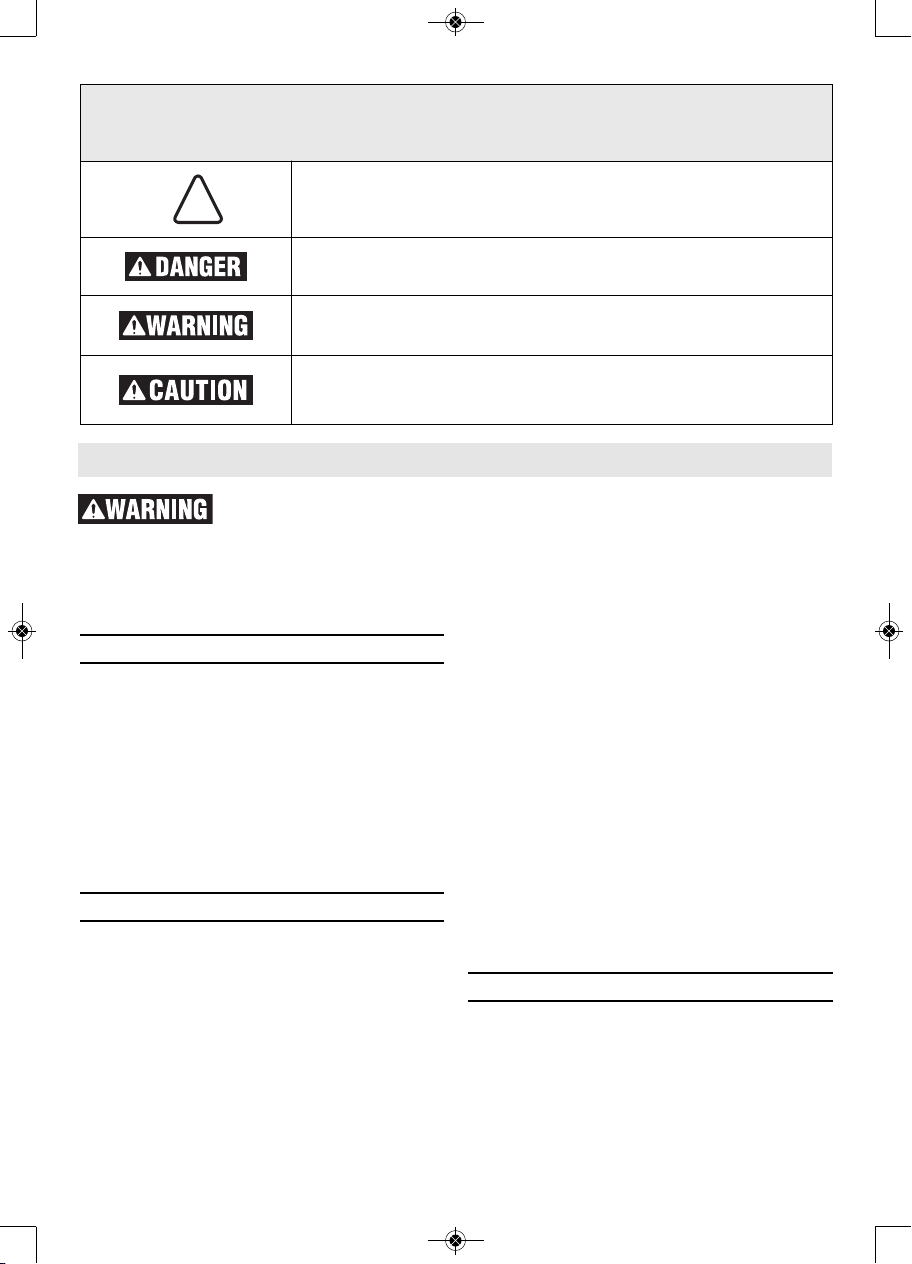
The definitions below describe the level of severity for each signal word. Please read the manual
and pay attention to these symbols.
!
This is the safety alert symbol. It is used to alert you to potential
personal injury hazards. Obey all safety messages that follow this
symbol to avoid possible injury or death.
DANGER indicates a hazardous situation which, if not avoided, will
result in death or serious injury.
WARNING indicates a hazardous situation which, if not avoided,
could result in death or serious injury.
CAUTION indicates a hazardous situation which, if not avoided,
could result in minor or moderate injury.
2610051568.qxp_GSR12V-300 12/19/18 1:15 PM Page 2
3
General Power Tool Safety Warnings
Use personal protective equipment. Always
wear eye protection. Protective equipment
such as dust mask, non-skid safety shoes,
hard hat, or hearing protection used for
appropriate conditions will reduce personal
injuries.
Prevent unintentional starting. Ensure the
switch is in the off-position before
connecting to power source and / or battery
pack, picking up or carrying the tool. Carrying
power tools with your finger on the switch or
energizing power tools that have the switch on
invites accidents.
Remove any adjusting key or wrench before
turning the power tool on. A wrench or a key
left attached to a rotating part of the power
tool may result in personal injury.
Do not overreach. Keep proper footing and
balance at all times. This enables better
control of the power tool in unexpected
situations.
Dress properly. Do not wear loose clothing
or jewelry. Keep your hair, clothing and
gloves away from moving parts. Loose
clothes, jewelry or long hair can be caught in
moving parts.
If devices are provided for the connection
of dust extraction and collection facilities,
ensure these are connected and properly
used. Use of dust collection can reduce dust-
related hazards.
Do not let familiarity gained from frequent
us e of tools all o w you to beco me
co m placent a nd ig n ore tool safety
principles. A careless action can cause
severe injury within a fraction of a second.
▶ Power tool use and care
Do not force the power tool. Use the correct
power tool for your application. The correct
power tool will do the job better and safer at
the rate for which it was designed.
Do not use the power tool if the switch does
not turn it on and off. Any power tool that
cannot be controlled with the switch is
dangerous and must be repaired.
Disconnect the plug from the power source
and/or remove the battery pack, i f
detachable, from the power tool before
making any adjustments, changing
accessories, or storing power tools. Such
preventive safety measures reduce the risk of
starting the power tool accidentally.
Store idle power tools out of the reach of
children and do not allow persons unfamiliar
with the power tool or these instructions to
operate the power tool. Power tools are
dangerous in the hands of untrained users.
Maintain power tools and accessories. Check
for misalignment or binding of moving parts,
breakage of parts and any other condition that
may affect the power tool’s operation. If
damaged, have the power tool repaired before
use. Many accidents are caused by poorly
maintained power tools.
Keep cutting tools sharp and clean. Properly
maintained cutting tools with sharp cutting
edges are less likely to bind and are easier to
control.
Use the power tool, accessories and tool
bits etc. in accordance with these instructions,
taking into account the working conditions
and the work to be performed. Use of the
power tool for operations different from
those intended could result in a hazardous
situation.
Keep handles and grasping surfaces dry,
clean and free from oil and grease. Slippery
handles and grasping surfaces do not allow
for safe handling and control of the tool in
unexpected situations.
▶ Battery tool use and care
Recharge only with the charger specified
by the manufacturer. A charger that is
suitable for one type of battery pack may
create a risk of fire when used with another
battery pack.
Use power tools only with specifically
designated battery packs. Use of any other
battery packs may create a risk of injury and
fire.
When battery pack is not in use, keep it
away from other metal objects like paper
clips, coins, keys, nails, screws, or other
small metal obj e c t s that can make a
connection from one terminal to another.
Shorting the battery terminals together may
cause burns or a fire.
Under abusive conditions, liquid may be
2610051568.qxp_GSR12V-300 12/19/18 1:15 PM Page 3

4
General Power Tool Safety Warnings
e
jected from the battery, avoid contact. If
contact accidentally occurs, flush with
water. If liquid contacts eyes, additionally
seek medical help. Liquid ejected from the
battery may cause irritation or burns.
Do not use a battery pack or tool that is
damaged or modified. Damaged or modified
batteries may exhibit unpredictable behaviour
resulting in fire, explosion or risk of injury.
Do not expose a battery pack or tool to fire
or excessive temperature. Exposure to fire
or temperature above 265 °F may cause
explosion.
Follow all charging instructions and do not
charge the battery pack or tool outside the
temperature r a n g e sp ecified in the
instructions. Charging improperly or at
t
emperatures outside the specified range
may damage the battery and increase the
risk of fire.
▶ Service
Have your power tool serviced by a qualified
re p air person us ing only iden t ical
replacement parts. This will ensure that the
safety of the power tool is maintained.
Never service damaged battery packs.
Service of battery packs should only be
performed by the manufacturer or authorized
service providers.
Safety Rules for Cordless Drill/Drivers
▶ Safety instructions for all
operations
Hold the power tool by insulated gripping
surfaces, when performing an operation
where the cutting accessory or fasteners
may contact hidden wiring. Cu t ting
accessory or fasteners contacting a “live”
wire may make exposed metal parts of the
power tool “live” and could give the operator
an electric shock.
▶ Safety instructions when using
long drill bits
Never operate at higher speed than the
maximum speed rating of the drill bit. At
higher speeds, the bit is likely to bend if
allowed to rotate freely without contacting
the workpiece, resulting in personal injury.
Always start drilling at low speed and with
the bit tip in contact with the workpiece.
At higher speeds, the bit is likely to bend if
allowed to rotate freely without contacting
the workpiece, resulting in personal injury.
Apply pressure only in direct line with the
bit and do not apply excessive pressure.
Bits can bend causing breakage or loss of
control, resulting in personal injury.
2610051568.qxp_GSR12V-300 12/19/18 1:15 PM Page 4

5
Additional Safety Warnings
GFCI and personal protection devices like
electrician’s rubber gloves and footwear will
further enhance your personal safety.
Do not use AC only rated tools with a DC
power supply. While the tool may appear to
work, the electrical components of the AC
rated tool are likely to fail and create a hazard
to the operator.
Keep handles dry, clean and free from oil
and grease. Slippery hands cannot safely
control the power tool.
Develop a periodic maintenance schedule for
your tool. When cleaning a tool be careful
not to disassemble any portion of the tool
since internal wires may be misplaced or
pinched or safety guard return springs may
be improperly mounted. Certain cleaning
agents such as gasoline, carbon tetrachloride,
ammonia, etc. may damage plastic parts.
Ensure the switch is in the off position
before inserting battery pack. Inserting the
battery pack into power tools that have the
switch on invites accidents.
Use vacuum system and protective gear
when drilling into materials which generate
dust.
Some dust created by
power sanding, sawing,
grinding, drilling, and other construction
activities contains chemicals known to cause
cancer, birth defects or other reproductive
harm. Some examples of these chemicals
are:
• Lead from lead-based paints,
• Crystalline silica from bricks and cement
and other masonry products, and
• Arsenic and chromium from chemically-
treated lumber.
Yo ur ris k from these expos ures varies,
depending on how often you do this type of
work. To reduce your exposure to these
chemicals: work in a well ventilated area, and
work with approved safety equipment, such
as those dust masks that are s pecially
designed to filter out microscopic particles.
2610051568.qxp_GSR12V-300 12/19/18 1:15 PM Page 5
6
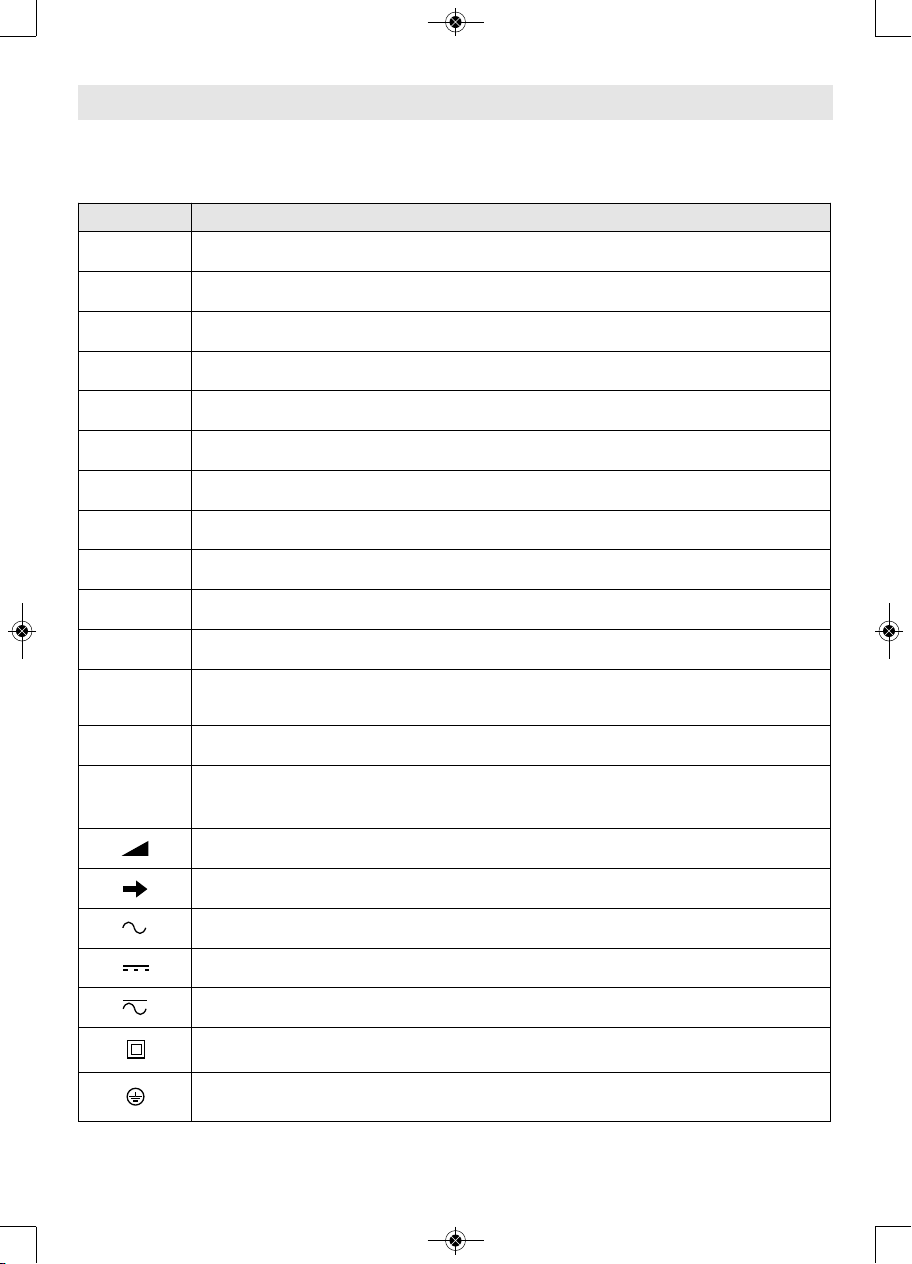
Symbols
Important: Some of the following symbols may be used on your tool. Please study them and
learn their meaning. Proper interpretation of these symbols will allow you to operate the tool
better and safer.
Symbol Designation / Explanation
V Volts (voltage)
Ah Amp hour (measurement of battery capacity)
A Amperes (current)
Hz Hertz (frequency, cycles per second)
W Watt (power)
kg Kilograms (weight)
min Minutes (time)
s Seconds (time)
⌀
Diameter (size of drill bits, grinding wheels, etc.)
n
0
No load speed (rotational speed at no load)
n Rated speed (maximum attainable speed)
.../min
Revolutions or reciprocation per minute (revolutions, strokes, surface speed,
orbits etc. per minute)
0 Off position (zero speed, zero torque...)
1, 2, 3, ...
I, II, III,
Selector settings (speed, torque or position settings. Higher number means
greater speed)
0
Infinitely variable selector with off (speed is increasing from 0 setting)
Arrow (action in the direction of arrow)
Alternating current (type or a characteristic of current)
Direct current (type or a characteristic of current)
Alternating or direct current (type or a characteristic of current)
Class II construction (designates double insulated construction tools)
Earthing terminal (grounding terminal)
2610051568.qxp_GSR12V-300 12/19/18 1:15 PM Page 6
7
Important: Some of the following symbols may be used on your tool. Please study them and
learn their meaning. Proper interpretation of these symbols will allow you to operate the tool
better and safer.
Symbols
Symbol Designation / Explanation
Designates Li-ion battery recycling program
Designates Ni-Cad battery recycling program
Alerts user to read manual
Alerts user to wear eye protection
This symbol designates that this tool is listed by Underwriters
Laboratories.
This symbol designates that this component is recognized by Underwriters
Laboratories.
This symbol designates that this tool is listed by Underwriters
Laboratories, to United States and Canadian Standards.
This symbol designates that this tool is listed by the Canadian Standards
Association.
This symbol designates that this tool is listed by the Canadian Standards
Association, to United States and Canadian Standards.
This symbol designates that this tool is listed by the Intertek Testing
Services, to United States and Canadian Standards.
This symbol designates that this tool complies to NOM Mexican Standards.
2610051568.qxp_GSR12V-300 12/19/18 1:15 PM Page 7
8
Functional Description and Specifications
Disconnect battery pack from tool or place the switch in the locked or off
position before making any assembly, adjustments or changing accessories.
Such preventive safety measures reduce the risk of starting the tool accidentally.
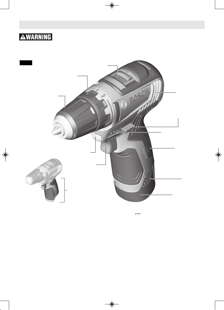
Fig. 1
Cordless Drill/Driver GSR12V-300
GEAR SHIFTER
FORWARD/REVERSING
LEVER & TRIGGER LOCK
RUBBERIZED
GRIP
BATTERY
RELEASE
TABS
BATTERY
PACK
INSULATED
GRIPPING
SURFACE
ADJUSTABLE
CLUTCH
KEYLESS
CHUCK
BATTERY CHARGE
CONDITION INDICATOR
LIGHTS
VARIABLE
SPEED
TRIGGER
SWITCH
BUILT IN
WORK LIGHT
VENTILATION
OPENINGS
Model number . . . . . . . . . .GSR12V-300
Voltage rating . . . . . . . . . .10.8V/12V MAX
No load speed 1 . . . . . . . . .n
0
0-460/min
No load speed 2 . . . . . . . . .n
0
0-1,750/min
Maximum Capacities
Chuck size . . . . . . . . . . . . . .3/8"
Screw sizes . . . . . . . . . . . . .9/32"
Mild metal . . . . . . . . . . . . . .3/8"
Wood . . . . . . . . . . . . . . . . . .3/4"
Allowed ambient temperature
– during charging . . . . . . . .32...113 °F (0...+45 °C)
– during operation/
storage . . . . . . . . . . . . . .–4...122 °F (–20...+50 °C)
Battery Packs/Chargers
Please refer to the battery/charger list, included with your tool.
2610051568.qxp_GSR12V-300 12/19/18 1:15 PM Page 8

Disconnect battery pack
from tool before making
any assembly, adjustments or changing
accesso r i e s . Such p r e v e ntive s a f e ty
measures reduce the risk of starting the
tool accidentally.
▶ Inserting and Releasing Battery
Pack
Release battery pack from tool by pressing
on both sides of the battery release tabs
and pull downward (Fig. 2 or 3).
To insert battery, align battery and slide
battery pack into tool until it locks into
position. Do not force.
If battery release tabs
are cracked or
otherwise damaged, do not insert into
tool. Battery can fall out during operation.
▶ Inserting Bits
Move reverse switch lever to the center
“OFF” position. Remove battery pack and
rotate the clutch ring to the drill bit symbol
“ ”. Rotate the chuck sleeve counterclockwise viewing from chuck end, and
open chuck t o a p p r o x i m a t e d r i l l b i t
diameter. Insert a clean bit up to the drill
bit flutes for small bits, or as far as it will
go for large bits. Close chuck by rotating
the chuck sleeve clockwise and securely
tighten by hand (Fig. 4).
Do not use the power of
the drill while grasping
chuck to loosen or tighten bit. Friction
burn or hand injury i s possible i f
attempting to grasp the spinning chuck.
▶ Belt Clip and Bit Tip Holder
Bosch GSR12V-300 comes with the option
to use a metal belt clip and a four piece bit
tip holder. Pry off the plastic cover from
the back of the drill to install these
accessories (Fig. 6).
▼ BELT CLIP
When the tool i s
attache d to the be l t ,
position yourself to avoid entanglement
with surrounding objects. Unexpected
entanglement could cause the tool to fall
resulti n g in injury t o the operator o r
bystanders.
The belt clip will allow you to conveniently
attach your tool to your belt. This feature
will allow you to have both hands free
when c l i m b i n g a la d d e r or moving t o
another work area.
9
Assembly
CHUCK SLEEVE
Fig. 4
DRILL BIT
BIT HOLDER
SCREWDRIVER BIT
BATTERY
RELEASE
TABS
Fig. 2
BATTERY
RELEASE
TABS
Fig. 3
Fig. 5
2610051568.qxp_GSR12V-300 12/19/18 1:15 PM Page 9

The belt clip can be positioned on either
side of the tool and secured to the back of
the tool with a mounting screw (Fig. 6).
Always make sure you securely tighten the
mounting screw before use.
To use clip, turn tool upside down and
attach to your belt.
▼ 4X BIT TIP HOLDER
Only store short
screwdriver bits in the
on-tool bit tip holder. Longer bits could
interfere with proper tool operation and
result in user injury.
The four piece bit tip holder can be used
for convenient on tool storage of your most
commonly used bits. The bit tip holder can
be used on its own, or in conjunction with
the belt clip accessory. If mounting both
the belt clip and bit holder accessory, be
sure t o place the b e l t clip accessory
between the bit tip holder accessory and
the tool. Always make sure you securely
tighten the mounting screw before use.
(Fig. 6).
10
Fig. 6
Operating Instructions
▶ Protection against Deep
Discharging
The lithium ion battery is protected against
deep discharging by the “Electronic Cell
Protection (ECP)”. When the battery is
empty, the tool is switched off by means of
a protective circuit.
▶ Variable Speed Controlled
Trigger Switch
Your tool is equipped with a variable speed
trigger switch. The tool can be turned
"ON" or "OFF" by squeezing or releasing the
trigger. The speed can be adjusted from
the minimum to maximum nameplate RPM
by the pressure you apply to the trigger.
Apply more pressure to increase the speed
and release pressure to decrease speed
(Fig. 1).
▶ Brake
When the trigg er switc h is release d it
ac tivate s the bra ke to stop the chuc k
quickly. This is especially useful in the
repetitive driving and removal of screws.
▶ Forward/Reversing Lever and
Trigger Lock
After t o o l us e , lo c k
trigger in “OFF”
position to help prevent accidental starts
and accidental discharge.
Your tool is equipped with a forwar d/
reversing lever and trigger lock located
above the trigger (Fig. 7). This lever was
designed for changing rotation of the bit,
and for locking the trigger in an “OFF”
position.
For forward rotation, (with chuck pointed
away from you) move the lever to the far
left.
For reverse rotation move the lever to the
far right. To activate trigger lock move lever
to the center off position.
BIT
HOLDER
BELT CLIP
Assembly
Fig. 7
2610051568.qxp_GSR12V-300 12/19/18 1:15 PM Page 10
11
Do not change direction
of rotation until the tool
comes to a complete stop. Shifting during
rotation of the chuck can cause damage to
the tool.
▶ Gear Shifting
Your tool is equipped with two separate
gear ranges, low gear and high gear. Low
ge a r pro v ides h i gh-torqu e and slow e r
drilling speeds for heavy duty work or for
driving screws. High gear provides faster
speeds for drilling lighter work. To change
speeds slide switch, to the high or low
position (Fig. 1).
ATTENTION: If your tool appears to be
running, but the chuck will not turn, check
to make sure the gear shifting switch is
pushed fully into desired setting.
▶ Adjustable Clutch
Yo u r too l fea t ures 2 1 clu t ch se ttings.
Output torque will increase as the clutch
ring, is rotated from 1 to 20. The drill
“ ” position will lock up the clutch to
permit drilling and driving heavy duty work
(Fig. 1).
▶ Autolock™
Your tool is equipped with an automatic
locking system. This feature will lock the
bit holder in one position when the trigger
switch is released. This will allow you to
tighten or loosen a nut or screw by rotating
the tool by hand with the switch off. This is
convenient when higher turning torque is
needed.
▶ Built-in Work Light
Your tool is also equipped with a light that
turns on automatically when the switch is
activat e d , fo r be t ter v i s i b i l i t y when
drilling/driving (Fig. 1).
▶ Battery Charge Condition
Indicator Lights
Your tool is equipped with charge condition
indicator lights (Fig. 1). The indicator lights
shows the charge condition of the battery
for a few second when the On/Off trigger is
pressed halfway or fully.
▶ Operating Tips
You will extend the life of your bits and do
neater work if you always put the bit in
contact with the work before pulling the
trigger. During the oper a tion, hold the tool
firmly and exert light, steady pressure. Too
much pressure at low speed will stall the
tool. Too little pressure will keep the bit
from cutting and cause excess friction by
sliding over the surface . This can be
damaging to both tool and bit.
▼ DRIVING NUTS AND BOLTS
Variable speed control must be used with
caution for driving nuts and bolts with
socket set attach ments. The technique is to
start slowly, increasing speed as the nut or
bolt runs down. Set the nut or bolt snugly
by s l o w i n g the drill to a s t o p . If t h i s
procedure is not followed, the tool will
have a tendency to torque or twist in your
hands when the nut or bolt seats.
▼ DRILLING
You will extend the life of your bits and do
neater work if you always put the bit in
contact with the work before pulling the
trigger. During the oper a tion, hold the tool
firmly and exert light, steady pressure. Too
much pressure at low speed will stall the
tool. Too little pressure will keep the bit
from cutting and cause excess friction by
sliding over the surface . This can be
damaging to both tool and bit.
▼ DRILLING WITH VARIABLE SPEED
The variable speed trigger allows you to
sl o wly i ncrease RPM. By using a sl o w
starting speed, you are able to keep the bit
from “wander ing”. You can increase the
speed as the bit “bites” into the work by
squeezing the trigger.
▼ DRIVING WITH VARIABLE SPEED
Variable speed drills will double as a power
screwdriver by using a screwdriver bit.
Prior to driving screws, pilot and clearance
holes should be drilled. Place the threaded
LED Capacity
Continuous lighting 3 x green > 2/3
Continuous lighting 2 x green > 1/3
Continuous lighting 1 x green < 1/3
Flashing light 1 x green reserve
Operating Instructions
2610051568.qxp_GSR12V-300 12/19/18 1:15 PM Page 11
end of the screw in the pilot or clearance
hole and start driving the screw slowly,
increasing the speed as the screw runs
down. Set the screw snugly by slowing to a
stop.
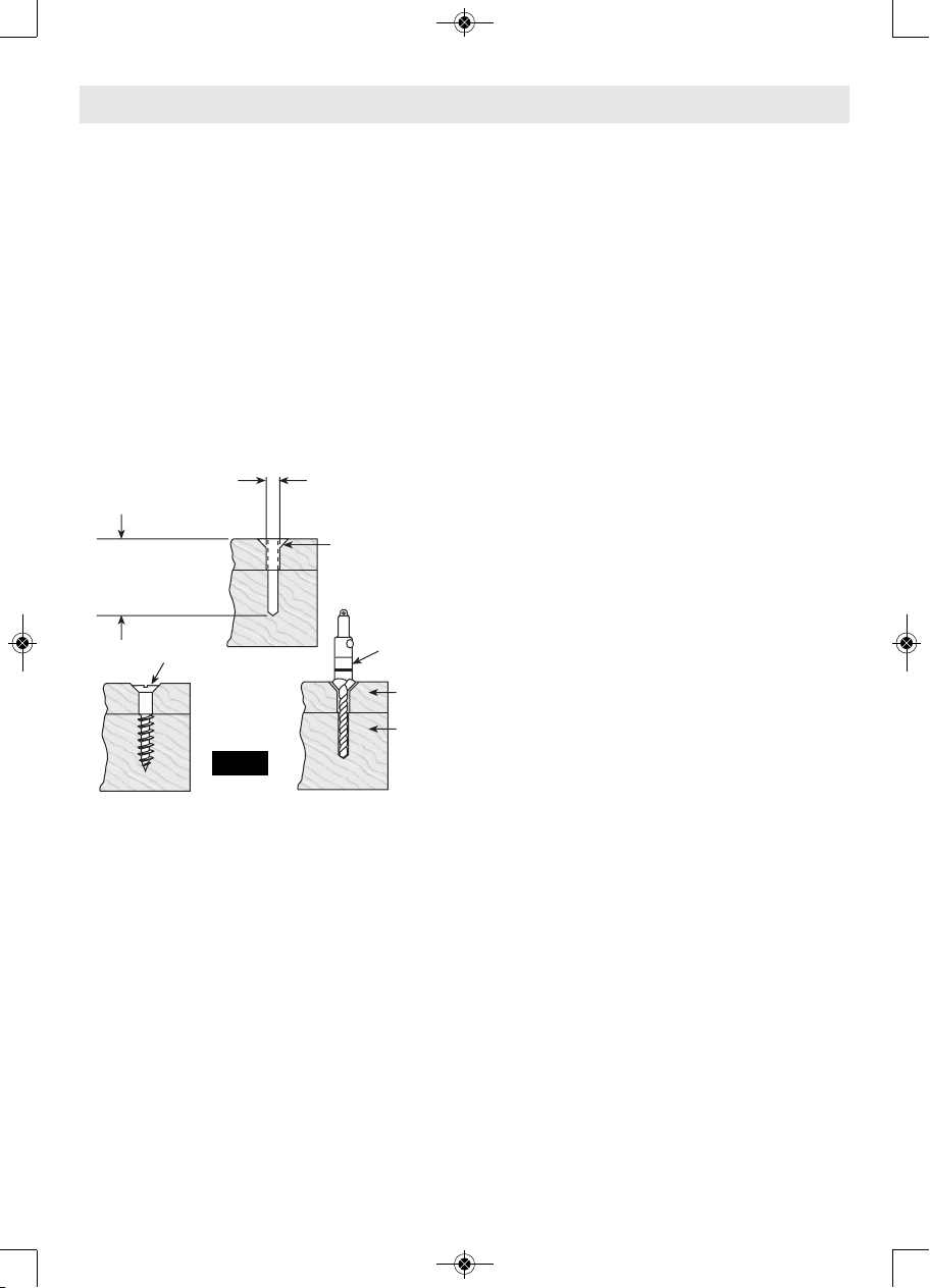
▼ FASTENING WITH SCREWS
The procedure shown in Fig. 8 will enable
you to fasten materials together using your
drill without stripping, splitting or
separating the material.
First, clamp the pieces together and drill
the hole 2/3 the diameter of the screw. If
th e ma terial is soft, dril l on ly 2/3 th e
proper length. If it is hard, drill the entire
length.
Second, unclamp the pieces and drill the
hole in the top piece of wood again to the
same diameter as the shank of the screw.
Third, if flat he a d screw is u s e d ,
countersink the hole to make the screw
flush with the surface. Realign the holes on
the two pieces and apply even pressure
when driving the screw. The screw shank
clearance hole in the first piece allows the
screw head to p u l l the p i e c e s tightly
together.
The adjustable screw drill accessory will do
all of these operations quickly and easily.
Screw drills are available for screw sizes
No. 6, 8, 10 and 12.
▼ DRILL BITS
Always inspect drill bits for excessive wear.
Use only bits that are sharp and in good
condition.
TWIST BITS: Available with straight and
reduced shanks for wood and light duty
metal drilling. High speed bits cut faster
and last longer on hard ma terials.
CARBIDE TIPPED BITS: Used for drilling
stone, con crete, plaster, cement and other
unusually hard nonmetals. Use continuous
heavy f e e d pres sure when e m p l o y i n g
carbide tip bits.
▼ DRILLING WOOD
Be certain workpiece is clamped or
anchored firm ly. Always apply pressure in a
straight line with the drill bit. Maintain
enough pressure to keep the drill “biting”.
When drilling holes in wood, twist bits can
be used. Twist bits may overheat unless
pulled out frequently to clear chips from
flutes.
Use a “back-up” block of wood for work
th a t is likel y to splinte r , suc h as thin
materials.
You will drill a cleaner hole if you ease up
on the pressure just before the bit breaks
through the wood. Then complete the hole
from the back side.
▼ DRILLING METAL
There are two rules for drilling hard
materials. First, the harder the material, the
greater the pres sure you need to apply to
the tool. Second, the harder the material,
the slower the speed. Here are a couple of
tips for drilling in metal. Lubri cate the tip
of the bit occasionally with cutting oil
except when drilling soft metals such as
alu minum, cop per or cast iron. If the hole
to be drilled is fairly large, drill a smaller
hole first, then enlarge to the required size,
it’s often faster in the long run. Main tain
enough pressure to assure that the bit does
not just spin in the hole. This will dull the
bit and greatly shorten its life.
12
Operating Instructions
2. Drill same
diameter as
screw shank.
3. Countersink
same diameter
as screw head.
1. Drill 2/3 diameter and
2/3 of screw length for
soft materials, full
length for hard
materials.
Adjustable
Screw
Drill
Screw
Apply a slight
even pressure
when driving
screws.
FASTENING
WITH SCREWS
FIG. 8
Top
Bottom
2610051568.qxp_GSR12V-300 12/19/18 1:15 PM Page 12