

Bosch GSR12V-140FC User Manual
IMPORTANT: IMPORTANT : IMPORTANTE:
Read Before Using Lire avant usage Leer antes de usar
Operating/Saf
Consignes de sécurité/d’utilisation
Instrucciones de funcionamiento y seguridad
GSR12V-140FC
ety Instructions
Call Toll Free for
Consumer Information
and Service Locations
1-877-BOSCH99 (1-877-267-2499) www.boschtools.com
For English Version Version française Versión en español
See page 2 Voir page 15 Ver la página 29
2610045267 A5.indd 1 11/23/16 9:49 AM
Pour obtenir des informa-
tions et les adresses de nos
centres de
service après-vente,
appelez ce numéro gratuit
Llame gratis para
obtener información
para el consumidor y
ubicaciones de servicio
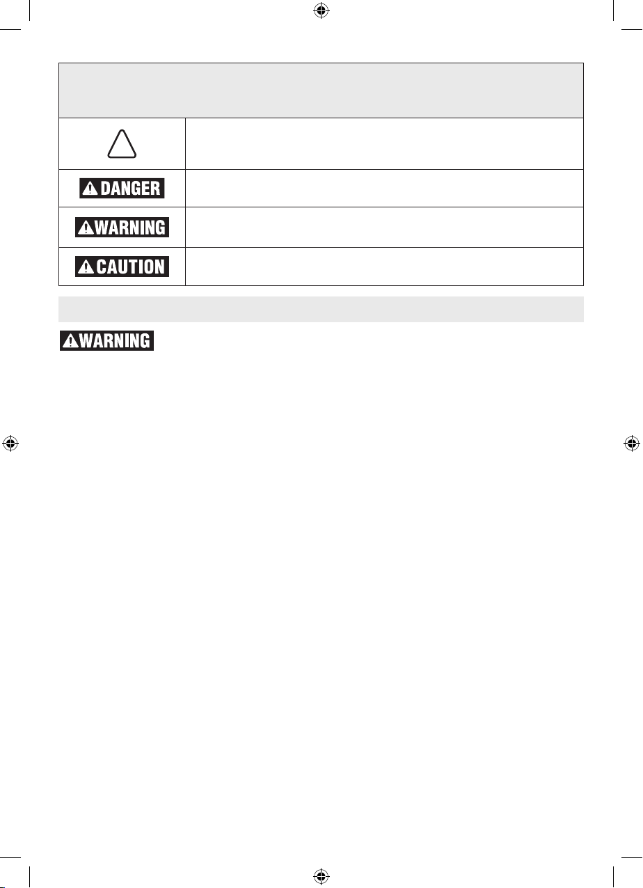
Safety Symbols
The definitions below describe the level of severity for each signal word. Please read the manual
!
and pay attention to these symbols.
This is the safety alert symbol. It is used to alert you to potential personal
injury hazards. Obey all safety messages that follow this symbol to avoid
possible injury or death.
DANGER indicates a hazardous situation which, if not avoided, will result
in death or serious injury.
WARNING indicates a hazardous situation which, if not avoided, could
result in death or serious injury.
CAUTION, used with the safety alert symbol, indicates a hazardous situation which, if not avoided, will result in minor or moderate injury.
General Power Tool Safety Warnings
Read all safety warnings and all instructions. Failure to follow the warnings and
instructions may result in electric shock, fire and/or serious injury.
SAVE ALL WARNINGS AND INSTRUCTIONS FOR FUTURE REFERENCE
The term “power tool” in the warnings refers to your mains-operated (corded) power tool or
battery-operated (cordless) power tool.
Work area safety
Keep work area clean and well lit. Cluttered or
dark areas invite accidents.
Do not operate power tools in explosive atmospheres, such as in the presence of flammable liquids, gases or dust. Power tools create
sparks which may ignite the dust or fumes.
Keep children and bystanders away while operating a power tool. Distractions can cause you
to lose control.
Electrical safety
Power tool plugs must match the outlet. Never
modify the plug in any way. Do not use any
adapter plugs with earthed (grounded) power
tools. Unmodified plugs and matching outlets will
reduce risk of electric shock.
Avoid body contact with earthed or grounded
surfaces such as pipes, radiators, ranges and
refrigerators. There is an increased risk of elec-
tric shock if your body is earthed or grounded.
Do not expose power tools to rain or wet conditions. Water entering a power tool will increase
the risk of electric shock.
Do not abuse the cord. Never use the cord
for carrying, pulling or unplugging the power tool. Keep cord away from heat, oil, sharp
edges or moving parts. Damaged or entangled
2
cords increase the risk of electric shock.
When operating a power tool outdoors, use
an extension cord suitable for outdoor use.
Use of a cord suitable for outdoor use reduces
the risk of electric shock.
If operating a power tool in a damp location is
unavoidable, use a Ground Fault Circuit Interrupter (GFCI) protected supply. Use of an GFCI
reduces the risk of electric shock.
Personal safety
Stay alert, watch what you are doing and use
common sense when operating a power tool.
Do not use a power tool while you are tired or
under the influence of drugs, alcohol or medication. A moment of inattention while operating
power tools may result in serious personal injury.
Use personal protective equipment. Always
wear eye protection. Protective equipment such
as dust mask, non-skid safety shoes, hard hat,
or hearing protection used for appropriate conditions will reduce personal injuries.
Prevent unintentional starting. Ensure the
switch is in the off-position before connecting
to power source and / or battery pack, picking
up or carrying the tool. Carrying power tools
with your finger on the switch or energizing power
tools that have the switch on invites accidents.
2610045267 A5.indd 2 11/23/16 9:49 AM

Remove any adjusting key or wrench before
turning the power tool on. A wrench or a key left
attached to a rotating part of the power tool may
result in personal injury.
Do not overreach. Keep proper footing and
balance at all times. This enables better control
of the power tool in unexpected situations.
Dress properly. Do not wear loose clothing or
jewelry. Keep your hair, clothing and gloves
away from moving parts. Loose clothes, jewelry
or long hair can be caught in moving parts.
If devices are provided for the connection of
dust extraction and collection facilities, ensure these are connected and properly used.
Use of dust collection can reduce dust-related
hazards.
Power tool use and care
Do not force the power tool. Use the correct
power tool for your application. The correct
power tool will do the job better and safer at the
rate for which it was designed.
Do not use the power tool if the switch does
not turn it on and off. Any power tool that cannot
be controlled with the switch is dangerous and
must be repaired.
Disconnect the plug from the power source
and/or the battery pack from the power tool
before making any adjustments, changing
accessories, or storing power tools. Such pre-
ventive safety measures reduce the risk of starting the power tool accidentally.
Store idle power tools out of the reach of children and do not allow persons unfamiliar with
the power tool or these instructions to operate the power tool. Power tools are dangerous in
the hands of untrained users.
Maintain power tools. Check for misalignment or binding of moving parts, breakage of
parts and any other condition that may affect
the power tool’s operation. If damaged, have
the power tool repaired before use. Many ac-
cidents are caused by poorly maintained power
tools.
Keep cutting tools sharp and clean. Properly
maintained cutting tools with sharp cutting edges
are less likely to bind and are easier to control.
Use the power tool, accessories and tool bits
etc. in accordance with these instructions,
taking into account the working conditions
and the work to be performed. Use of the pow-
er tool for operations different from those intended could result in a hazardous situation.
Battery tool use and care
Recharge only with the charger specified by
the manufacturer. A charger that is suitable for
one type of battery pack may create a risk of fire
when used with another battery pack.
Use power tools only with specifically designated battery packs. Use of any other battery
packs may create a risk of injury and fire.
When battery pack is not in use, keep it away
from other metal objects like paper clips,
coins, keys, nails, screws, or other small metal objects that can make a connection from
one terminal to another. Shorting the battery
terminals together may cause burns or a fire.
Under abusive conditions, liquid may be ejected from the battery; avoid contact. If contact
accidentally occurs, flush with water. If liquid
contacts eyes, additionally seek medical help.
Liquid ejected from the battery may cause irritation or burns.
Service
Have your power tool serviced by a qualified
repair person using only identical replacement parts. This will ensure that the safety of the
power tool is maintained.
Safety Rules for Cordless Drill/Drivers
Use auxiliary handle(s) if supplied with the
tool. Loss of control can cause personal injury.
Hold power tool by insulated gripping surfaces, when performing an operation where the
cutting accessory may contact hidden wiring.
Cutting accessory contacting a “live” wire may
make exposed metal parts of the power tool “live”
and could give the operator an electric shock.
Use clamps or another practical way to se-
2610045267 A5.indd 3 11/23/16 9:49 AM
cure and support the workpiece to a stable
platform. Holding the work by hand or against
your body leaves it unstable and may lead to loss
of control.
Do not drill, fasten or break into existing walls
or other blind areas where electrical wiring
may exist. If this situation is unavoidable, dis-
connect all fuses or circuit breakers feeding this
worksite.
3

Always hold the tool with both hands. If the
bit jams two hands will give you maximum control
over torque reaction or kickback.
Always wear safety goggles or eye protection
when using this tool. Use a dust mask or respirator for applications which generate dust.
Secure the material being drilled. Never hold
it in your hand or across legs. Unstable sup-
port can cause the drill bit to bind causing loss of
control and injury.
Disconnect battery pack from tool or place
the switch in the locked or off position before making any assembly, adjustments or
changing accessories. Such preventive safety
measures reduce the risk of starting the tool accidentally.
Position yourself to avoid being caught between the tool or side handle and walls or
posts. Should the bit become bound or jammed
in the work, the reaction torque of the tool could
crush your hand or leg.
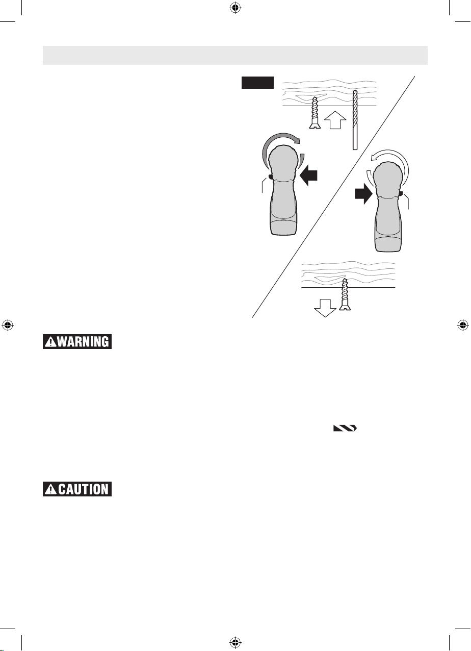
If the bit becomes bound in the workpiece,
release the trigger immediately, reverse the
direction of rotation and slowly squeeze the
trigger to back out the bit. Be ready for a strong
Additional Safety Warnings
reaction torque. The drill body will tend to twist in
the opposite direction as the drill bit is rotating.
Do not grasp the tool or place your hands too
close to the spinning chuck or drill bit. Your
hand may be lacerated.
When installing a bit, insert the shank of the
bit well within the chuck. If the bit is not insert-
ed deep enough, the grip of the chuck over the
bit is reduced and the loss of control is increased.
After bit insertion, pull on bit to ensure it is locked.
Do not use dull or damaged bits and accessories. Dull or damaged bits have a greater ten-
dency to bind in the workpiece.
When removing the bit from the tool avoid
contact with skin and use proper protective
gloves when grasping the bit or accessory.
Accessories may be hot after prolonged use.
Check to see that keys and adjusting wrenches are removed from the drill before switching
the tool “ON”. Keys or wrenches can fly away at
high velocity striking you or a bystander.
Do not run the drill while carrying it at your
side. A spinning drill bit could become entangled
with clothing and injury may result.
GFCI and personal protection devices like electrician’s rubber gloves and footwear will further
enhance your personal safety.
Do not use AC only rated tools with a DC power supply. While the tool may appear to work, the
electrical components of the AC rated tool are
likely to fail and create a hazard to the operator.
Keep handles dry, clean and free from oil and
grease. Slippery hands cannot safely control the
power tool.
Develop a periodic maintenance schedule for
your tool. When cleaning a tool be careful not
to disassemble any portion of the tool since
internal wires may be misplaced or pinched
or safety guard return springs may be improperly mounted. Certain cleaning agents such as
gasoline, carbon tetrachloride, ammonia, etc.
may damage plastic parts.
Ensure the switch is in the off position before
inserting battery pack. Inserting the battery
pack into power tools that have the switch on invites accidents.
ing, drilling, and other construction activities
contains chemicals known to cause cancer,
birth defects or other reproductive harm.
Some examples of these chemicals are:
• Leadfromlead-basedpaints,
• Crystallinesilica frombricksandcementand
other masonry products, and
• Arsenicandchromium from chemically-treated lumber.
Your risk from these exposures varies, depending
on how often you do this type of work. To reduce
your exposure to these chemicals: work in a well
ventilated area, and work with approved safety
equipment, such as those dust masks that are
specially designed to filter out microscopic particles.
Some dust created by power sanding, sawing, grind-
4
2610045267 A5.indd 4 11/23/16 9:49 AM
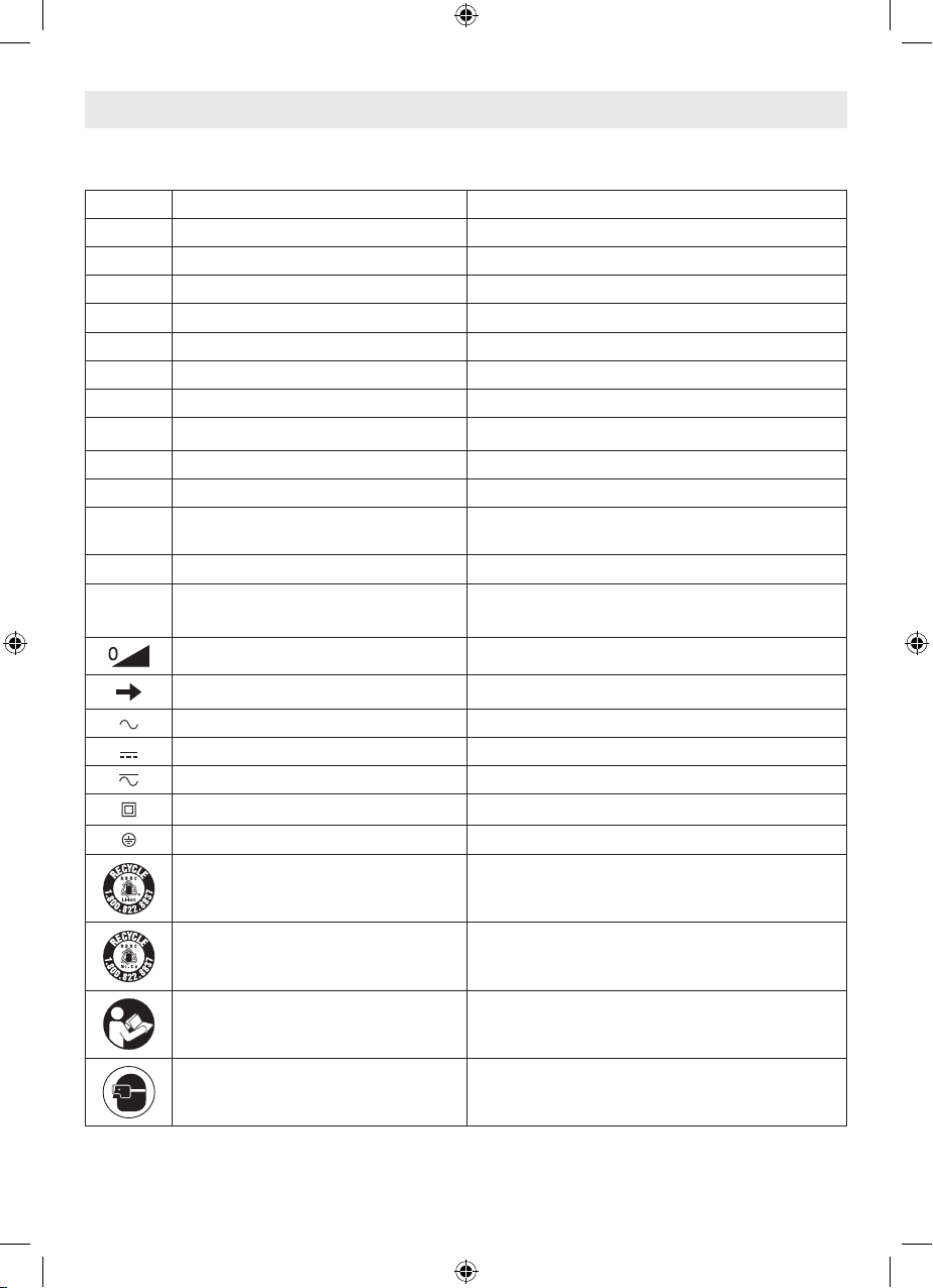
Symbols
IMPORTANT: Some of the following symbols may be used on your tool. Please study them and learn
their meaning. Proper interpretation of these symbols will allow you to operate the tool better and safer.
Symbol Name Designation/Explanation
V Volts Voltage (potential)
A Amperes Current
Hz Hertz Frequency (cycles per second)
W Watt Powe r
kg Kilograms Weight
min Minutes Time
s Seconds Time
⌀
.../min Revolutions or reciprocation per min-
1, 2, 3, ...
I, II, III,
Diameter Size of drill bits, grinding wheels, etc.
No load speed Rotational speed, at no load
n
0
n Rated speed Maximum attainable speed
ute
0 Off position Zero speed, zero torque...
Selector settings Speed, torque or position settings. Higher num-
Infinitely variable selector with off Speed is increasing from 0 setting
Arrow Action in the direction of arrow
Alternating current Type or a characteristic of current
Direct current Type or a characteristic of current
Alternating or direct current Type or a characteristic of current
Class II construction Designates Double Insulated Construction tools.
Earthing terminal Grounding terminal
Li-ion RBRC seal Designates Li-ion battery recycling program
Revolutions, strokes, surface speed, orbits etc.
per minute
ber means greater speed
Ni-Cad RBRC seal Designates Ni-Cad battery recycling program
Read manual symbol Alerts user to read manual
Wear eye protection symbol Alerts user to wear eye protection
5
2610045267 A5.indd 5 11/23/16 9:49 AM
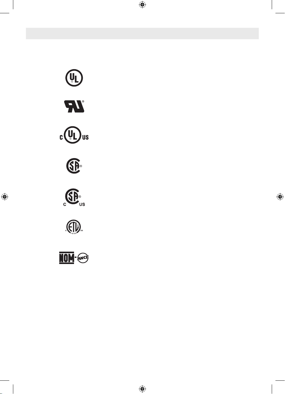
Symbols (continued)
IMPORTANT: Some of the following symbols may be used on your tool. Please study them and learn
their meaning. Proper interpretation of these symbols will allow you to operate the tool better and safer.
This symbol designates that this tool is listed by Underwriters Laboratories.
This symbol designates that this component is recognized by Underwriters Laboratories.
This symbol designates that this tool is listed by Underwriters Laboratories, to United States and Canadian
Standards.
This symbol designates that this tool is listed by the Canadian Standards Association.
This symbol designates that this tool is listed by the Canadian Standards Association, to United States and Canadian Standards.
This symbol designates that this tool is listed by the Intertek Testing Services, to United States and Canadian
Standards.
This symbol designates that this tool complies to NOM
Mexican Standards.
6
2610045267 A5.indd 6 11/23/16 9:49 AM
Disconnect battery pack from tool before making any assembly, adjustments
14
or changing accessories. Such preventive safety measures reduce the risk of
starting the tool accidentally.
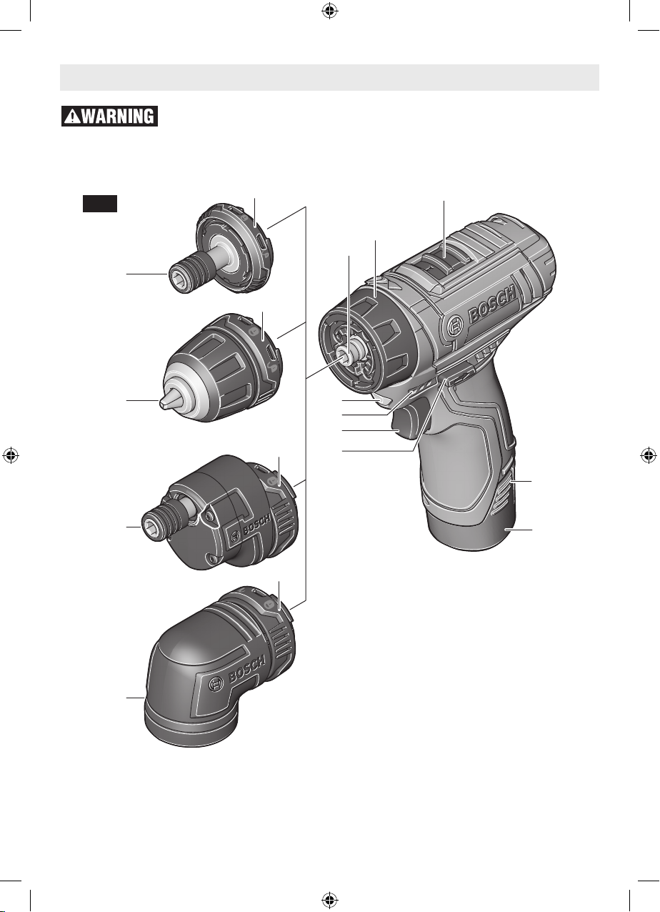
Functional Description
Cordless Drill/Driver
Fig. 1
10
11
12
13
14
14
14
3
2
1
9
8
7
6
4
5
1 Hex Drive
2 Adjustable clutch
3 Gear shifter
4 Battery release tabs
5 Battery pack
6 Forward/reversing lever and trigger lock
7 Variable speed trigger switch
8 Battery charge status indicator lights
9 Built in work light
10 Bit holder adapter
11 Drill chuck adapter
12 Offset adapter
13 Right angle adapter
14 Lock ring
7
2610045267 A5.indd 7 11/23/16 9:49 AM
Specifications
Model number GSR12V-140FC
Voltage rating 10.8V/12V
No load speed 1 n
No load speed 2 n
Bit holder 1/4" (6.35mm) Hex-shank with power groove
Drill chuck Ø 3/8" (10mm)
Driving screw sizes 9/32" (7mm)
Drilling wood 3/4" (19mm)
Please refer to the Charger Manual included with your tool.
NOTE: For tool specifications refer to the nameplate on your tool.
0-400/min
0
0-1,300/min
0
Maximum Capacities:
Battery Packs/Chargers
MAX
Assembly
Disconnect battery pack from tool before making any assembly, adjustments
starting the tool accidentally.
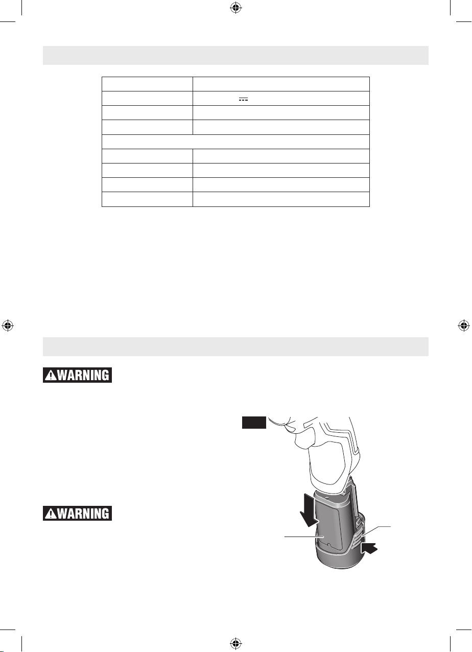
Inserting and releasing
or changing accessories. Such preventive safety measures reduce the risk of
Fig. 2
battery pack
Release battery pack 5 from tool by pressing on
both sides of the battery release tabs 4 and pulling battery downward (Fig. 2).
To insert battery, align battery and slide battery
pack 5 into tool until it locks into position. Do not
force.
If battery release tabs are
aged, do not insert into tool. Battery can fall out
during operation.
cracked or otherwise dam-
5
8
2610045267 A5.indd 8 11/23/16 9:49 AM
4

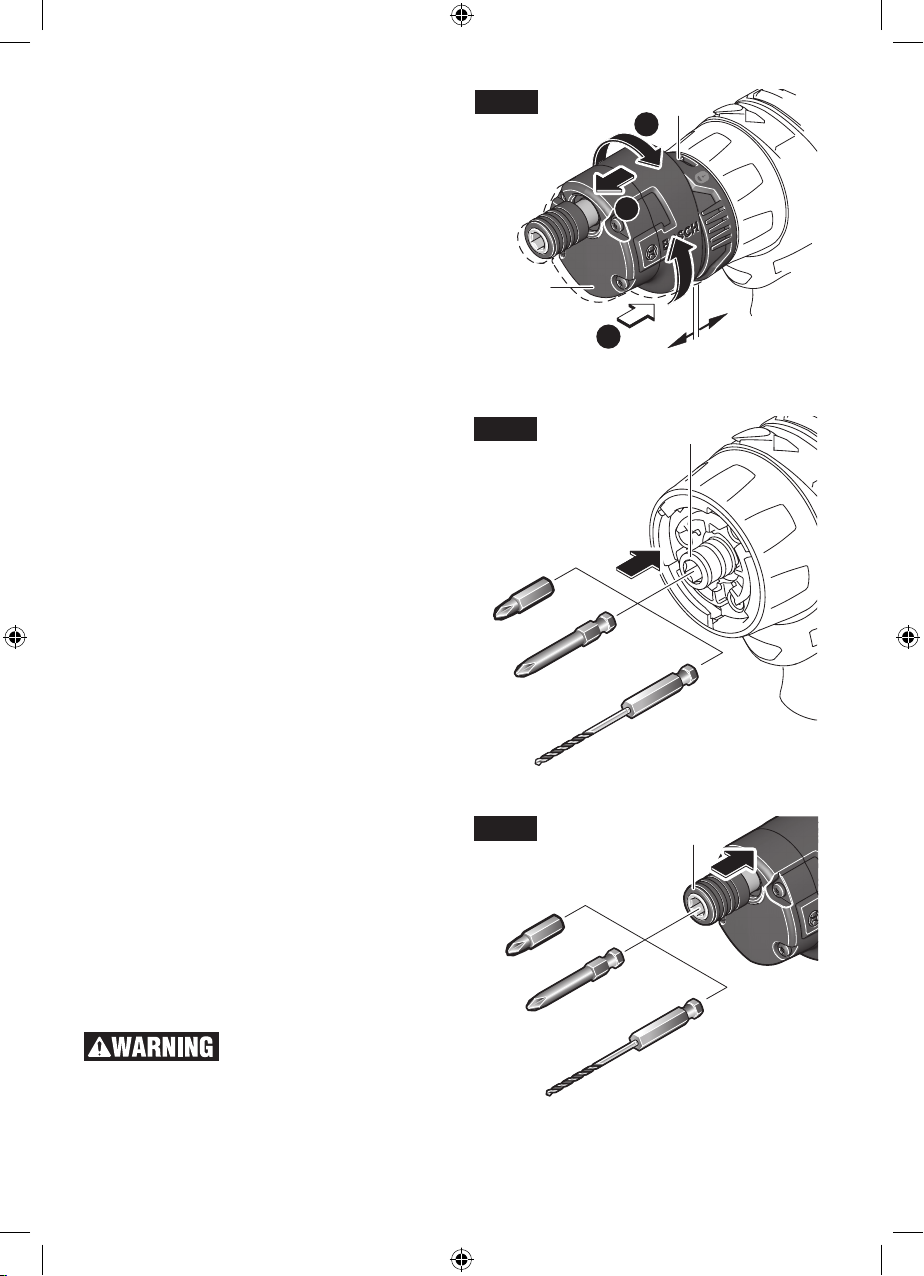
Mounting and Removing Adapters
)
A. Make sure the hex drive 1 is free. Pull out any
bit you might have used.
B. Insert the hex shaft of an adapter into the drive
1 and push the adapter until it snaps in place.
You may need to rotate the adapter a little.
C. Lock the adapter in place by turning the lock
ring 14 in the direction shown until it clicks
(Fig. 3).
To remove any adapter, turn the lock ring 14 in
the direction shown until it clicks. Pull the adapter
away from the tool (Fig. 4).
Fig. 3
1
B
A
C
14
Using Right Angle Adapter
You can rotate the right angle adapter 13 to any
position around the axis of the tool in 9° increments. See Fig. 5.
A. Make sure the adapter is locked on the tool.
Pull the adapter 13 away from the lock ring 14
approximately 3/16” (5mm).
B. Rotate the adapter 13 to a desired position.
C. Release the pull and let the adapter return to
the locked position.
The right angle adapter’s interface 13a is identical to the interface of the power tool. You can
attach the other 3 adapters to it the same way
as the adapters are mounted to the tool (See
“Mounting and Removing Adapters”).
Fig. 4
Fig. 5
13a
14
max. 3/16” (5mm
B
A
14
13
C
9
2610045267 A5.indd 9 11/23/16 9:49 AM
Using Offset Adapter
You can rotate the offset adapter 12 to any position around the axis of the tool in 9° increments.
See Fig. 6.
A. Make sure the adapter is locked on the tool.
Pull the adapter 12 away from the lock ring 14
by approximately 3/16” (5mm).
B. Rotate the adapter 12 to desired position.
C. Let the adapter snap back towards the lock
ring 14.
Fig. 6
14
B
A
12
C
max. 3/16” (5mm)
Inserting and Removing Bits
(Main Hex Drive)
You can insert any 1/4” hex bits directly into the
main hex drive 1 without using any of the adapters (Fig. 7). The hex drive is magnetized and will
prevent the bits from falling out during light drilling
or driving.
To remove a bit, simply pull it out.
Inserting and Removing Bits (Hex
Chuck)
Bit holder adapter 10 and offset adapter 12 have
a chuck that accepts any 1/4” hex bit.
To insert an accessory, simply pull locking sleeve
12a backward, insert desired accessory into
chuck and release the locking sleeve to lock the
bit (Fig. 8).
To remove an accessory, pull locking sleeve
backward and remove it from the chuck.
To avoid loss of control, ensure bit is locked in chuck
by pulling on bit after it has been inserted.
Fig. 7
Fig. 8
1
12a
10
2610045267 A5.indd 10 11/23/16 9:49 AM
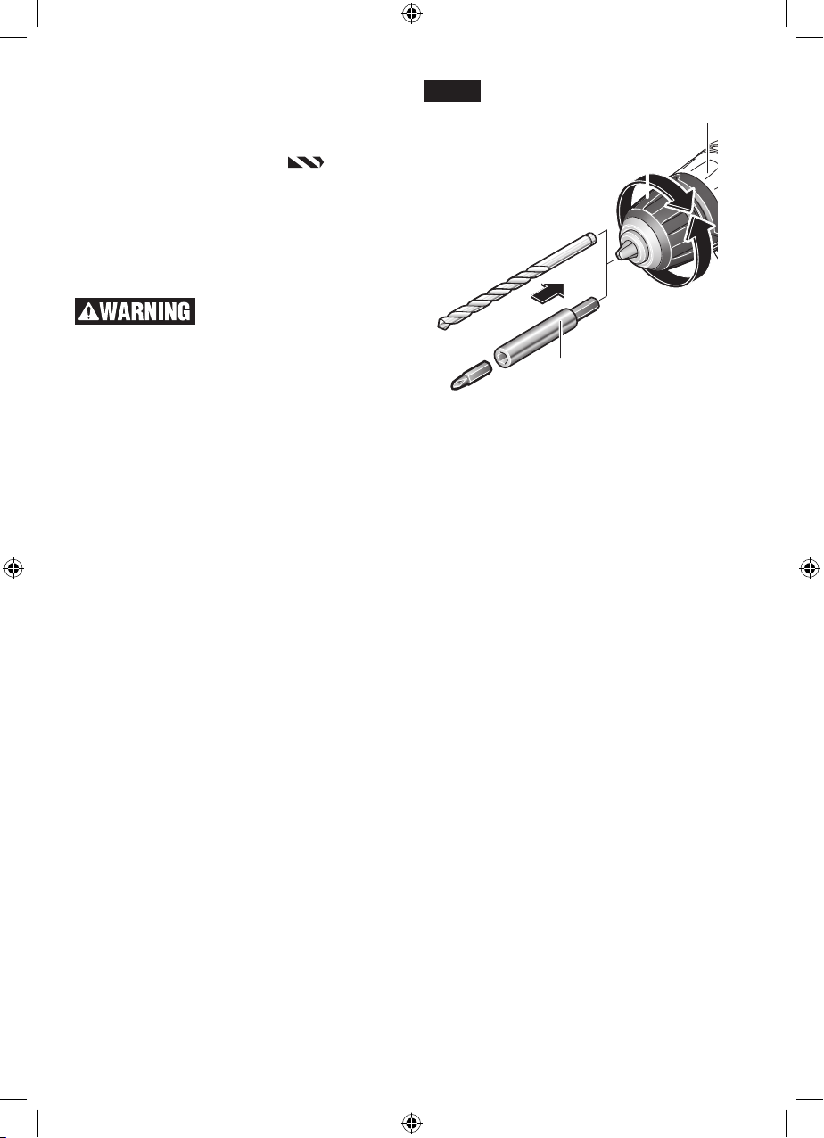
Inserting and Removing Bits
(Drill Chuck)
Move forward/reversing lever 6 to the center “OFF”
position. Remove battery pack 5 and rotate the
clutch ring 2 to the drill bit symbol
chuck sleeve 11a counter-clockwise viewing from
chuck end, and open chuck to approximate drill
bit diameter. Insert a clean bit up to the drill bit
flutes for small bits, or as far as it will go for large
bits. Close chuck by rotating the chuck sleeve
11a clockwise and securely tighten by hand (Fig.
9).
Do not use the power of the
drill while grasping chuck
to loosen or tighten bit. Friction burn or hand
injury is possible if attempting to grasp the spinning chuck.
. Rotate the
Fig. 9
11a 2
16
11
2610045267 A5.indd 11 11/23/16 9:49 AM
Operating Instructions
Protection Against
Deep Discharging
The lithium ion battery is protected against deep
discharging by the “Electronic Cell Protection
(ECP)”. When the battery is discharged, the tool
is switched off by means of a protective circuit.
Variable Speed Controlled Trigger
Switch
Your tool is equipped with a variable speed trigger switch. The tool can be turned “ON” or “OFF”
by squeezing or releasing the trigger. The speed
can be adjusted from the minimum to maximum
nameplate RPM by the pressure you apply to
the trigger. Apply more pressure to increase the
speed and release pressure to decrease speed
(Fig. 1).
Brake
When the trigger switch is released it activates
the brake to stop the chuck quickly. This is especially useful in the repetitive driving and removal
of screws.
Forward/Reversing Lever
and Trigger Lock
After tool use, lock trigger
in “OFF” position to help
prevent accidental starts and accidental discharge.
Your tool is equipped with a forward/reversing lever and trigger lock 6 located above the trigger
(Fig. 10). This lever was designed for changing
rotation of the bit, and for locking the trigger in an
“OFF” position.
For forward rotation, (with chuck pointed away
from you) move the lever to the far left.
For reverse rotation move the lever to the far right.
To activate trigger lock move lever to the center
off position.
Do not change direction of
rotation until the tool comes
to a complete stop. Shifting during rotation of
the chuck can cause damage to the tool.
Gear Shifting
Your tool is equipped with two separate gear
ranges, low gear and high gear. Low gear provides high-torque and slower drilling speeds for
heavy duty work or for driving screws. High gear
provides faster speeds for drilling lighter work. To
Fig. 10
6
6
change speeds slide switch, to the high or low
position (Fig. 1).
ATTENTION: If your tool appears to be running,
but the chuck will not turn, check to make sure
the gear shifting switch is pushed fully into desired setting.
Adjustable Clutch
Your tool features 21 clutch settings. Output
torque will increase as the clutch ring, is rotated
from 1 to 20. The drill “
up the clutch to permit drilling and driving heavy
duty work (Fig. 1).
” position will lock
Autolock™
Your tool is equipped with an automatic locking
system. This feature will lock the bit holder in one
position when the trigger switch is released. This
will allow you to tighten or loosen a nut or screw
by rotating the tool by hand with the switch off.
This is convenient when higher turning torque is
needed.
Built-in Work Light
Your tool is also equipped with a light that turns
on automatically when the switch is activated, for
better visibility when drilling/driving (Fig. 1).
12
2610045267 A5.indd 12 11/23/16 9:49 AM

Battery Charge Condition
Indicator Lights
Your tool is equipped with charge condition indicator lights (Fig. 1). The indicator lights shows the
charge condition of the battery for a few second
when the On/Off trigger is pressed halfway or
fully.
Operating Tips
LED Capacity
Continuous lighting 3 x green > 2/3
Continuous lighting 2 x green > 1/3
Continuous lighting 1 x green < 1/3
Flashing light 1 x green reserve
Driving Nuts And Bolts
Variable speed control must be used with caution
for driving nuts and bolts with socket set attachments. The technique is to start slowly, increasing
speed as the nut or bolt runs down. Set the nut
or bolt snugly by slowing the drill to a stop. If this
procedure is not followed, the tool will have a tendency to torque or twist in your hands when the
nut or bolt seats.
Drilling
You will extend the life of your bits and do neater
work if you always put the bit in contact with the
work before pulling the trigger. During the opera tion, hold the tool firmly and exert light, steady
pressure. Too much pressure at low speed will
stall the tool. Too little pressure will keep the bit
from cutting and cause excess friction by sliding
over the surface. This can be damaging to both
tool and bit.
Drilling With Variable Speed
The variable speed trigger allows you to slowly
increase RPM. By using a slow starting speed,
you are able to keep the bit from “wander ing”. You
can increase the speed as the bit “bites” into the
work by squeezing the trigger.
Driving With Variable Speed
Variable speed drills will double as a power
screwdriver by using a screwdriver bit. Prior to
driving screws, pilot and clearance holes should
be drilled. Place the threaded end of the screw in
the pilot or clearance hole and start driving the
screw slowly, increasing the speed as the screw
runs down. Set the screw snugly by slowing to a
stop.
Fastening With Screws
The procedure shown in Fig. 11 will enable you to
fasten materials together using your drill without
stripping, splitting or separating the material.
First, clamp the pieces together and drill the hole
2/3 the diameter of the screw. If the material is
FASTENING WITH
SCREWS
1. Drill 2/3 diameter
and 2/3 of screw
length for soft materials, full length for
hard materials.
Apply a slight even
pressure when driving
screws.
2. Drill same di-
ameter as screw
shank.
3. Countersink
same diameter
as screw head.
Screw
Top
Bottom
Fig. 11
soft, drill only 2/3 the proper length. If it is hard,
drill the entire length.
Second, unclamp the pieces and drill the hole in
the top piece of wood again to the same diameter
as the shank of the screw.
Third, if flat head screw is used, countersink the
hole to make the screw flush with the surface.
Realign the holes on the two pieces and apply
even pressure when driving the screw. The screw
shank clearance hole in the first piece allows the
screw head to pull the pieces tightly together.
The adjustable screw drill accessory will do all of
these operations quickly and easily. Screw drills
are available for screw sizes No. 6, 8, 10 and 12.
Drill Bits
Always inspect drill bits for excessive wear. Use
only bits that are sharp and in good condition.
TWIST BITS: Available with straight and reduced
shanks for wood and light duty metal drilling. High
speed bits cut faster and last longer on hard materials.
CARBIDE TIPPED BITS: Used for drilling stone,
con crete, plaster, cement and other unusually hard nonmetals. Use continuous heavy feed
pres sure when employing carbide tip bits.
13
2610045267 A5.indd 13 11/23/16 9:49 AM
Drilling Wood
Be certain workpiece is clamped or anchored
firm ly. Always apply pressure in a straight line with
the drill bit. Maintain enough pressure to keep the
drill “biting”.
When drilling holes in wood, twist bits can be
used. Twist bits may overheat unless pulled out
frequently to clear chips from flutes.
Use a “back-up” block of wood for work that is
likely to splinter, such as thin materials.
You will drill a cleaner hole if you ease up on the
pressure just before the bit breaks through the
wood. Then complete the hole from the back side.
Maintenance
Drilling Metal
There are two rules for drilling hard materials.
First, the harder the material, the greater the
pres sure you need to apply to the tool. Second,
the harder the material, the slower the speed.
Here are a couple of tips for drilling in metal.
Lubri cate the tip of the bit occasionally with cutting oil except when drilling soft metals such as
alu minum, cop per or cast iron. If the hole to be
drilled is fairly large, drill a smaller hole first, then
enlarge to the required size, it’s often faster in the
long run. Main tain enough pressure to assure
that the bit does not just spin in the hole. This will
dull the bit and greatly shorten its life.
Service
NO USER SERVICEABLE
PARTS INSIDE. Preventive
maintenance performed by un au thorized personnel may result in misplacing of internal
wires and components which could cause serious hazard. We recom mend that all tool ser-
vice be performed by a Bosch Factory Service
Center or Authorized Bosch Service Station.
SERVICE MEN: Disconnect tool and/or charger
from power source before servicing.
Batteries
Be alert for battery packs that are nearing
their end of life. If you notice decreased tool
performance or significantly shorter running time
between charges then it is time to replace the
battery pack. Failure to do so can cause the tool
to operate improperly or damage the charger.
Tool Lubrication
Your Bosch tool has been properly lubricated and
is ready for use.
Motors
The motor in your tool has been engineered for
many hours of dependable service. To maintain
peak efficiency of the motor, we recommend it
be examined every six months. Only a genuine
Bosch replacement motor specially designed for
your tool should be used.
Cleaning
To avoid accidents, always
disconnect the tool and/or
charger from the power supply before cleaning. The tool may be cleaned most effectively
with com pressed dry air. Always wear safety
goggles when cleaning tools with compressed air.
Ventilation openings and switch levers must be
kept clean and free of foreign matter. Do not
attempt to clean by inserting pointed objects
through opening.
Certain cleaning agents and
solvents damage plastic
parts. Some of these are: gasoline, car bon tetra-
chloride, chlorinated cleaning solvents, ammonia
and household detergents that contain ammonia.
14
2610045267 A5.indd 14 11/23/16 9:49 AM
 Loading...