

Bosch GBM 10, GBM 10 RE, GBM 10 SRE, GBM 10-2 RE, GBM 13-2 Operating Instructions Manual
...
Bedienungsanleitung
Operating Instructions
Instructions d’emploi
Instrucciones de servicio
Manual de instruções
Istruzioni d’uso
Gebruiksaanwijzing
Betjeningsvejledning
Bruksanvisning
Brukerveiledningen
Käyttöohje
Oδηγία χειρισµού
Kullanım kılavuzu
GBM 10
GBM 10 RE
GBM 10 SRE
GBM 10-2 RE
GBM 13-2
GBM 13-2 RE
Deutsch
English
Français
Español
Português
Italiano
Nederlands
Dansk
Svenska
Norsk
Suomi
Eλληνικά
Türkçe

2 • 2 609 932 285 • 03.02
2 608 180 003
(BS 35)
2 608 180 004
(BS 45)
1 612 025 024
1 613 001 005
2 608 030 053
(MS 65)
2 608 030 055
(MS 80)
GBM 10 SRE:
2 605 438 328
2 608 040 057
GBM 10:
2 608 572 032
GBM 10 RE/
GBM 10 SRE/
GBM 10-2 RE:
2 608 572 030
GBM 13-2:
2 608 572 036
GBM 13-2 RE:
2 608 572 105
GBM 10:
1 608 571 054
GBM 10 RE/
GBM 10 SRE/
GBM 10-2 RE:
1 608 571 061
GBM 13-2:
1 608 571 048
GBM 13-2 RE:
1 608 571 062
3 • 2 609 932 285 • 03.02
GBM 10 SRE:
2 600 460 026
2 607 990 050
(S 41)
1
2
3
4
5
6
7
8
9
10
11
GBM 13-2 RE
A
x
4 • 2 609 932 285 • 03.02
8
9
10
B
12
13
C
1
D
GBM 10 RE/
GBM 10-2 RE/
GBM 13-2 RE
14
2
15
E
G
GBM 10 SRE
16
14 17
GBM 10 SRE
F
H
13
18
GBM 10/
GBM 10 RE
20
18
5 • 2 609 932 285 • 03.02
19

Gerätekennwerte
Bohrmaschine GBM ... 10 10 RE 10 SRE 10-2 RE 13-2 13-2 RE
Bestellnummer 0 601 ... 135 0.. 135 5.. 137 5.. 168 5.. 169 0.. 169 5..
Nennaufnahme [W] 450 450 420 500 550 550
Abgabeleistung [W] 220 220 220 270 285 285
Leerlaufdrehzahl
1. Gang [min-1] 2 000 0–2 200 0– 2 600 0 –1 150 1 000 0–1 000
2. Gang [min-1] – – – 0– 2 100 1 900 0– 1 900
Nenndrehzahl
1. Gang [min-1] 1 300 0–1 300 0– 1 600 0 –800 550 0–550
2. Gang [min-1] – – – 0– 1 500 1 000 0– 1 000
Drehmoment bei max.
Abgabeleistung (1./2. Gang)
Stufenlose
Drehzahlregulierung
Rechts-/Linkslauf –
Bohrfutterspannbereich max. [mm] 1–10 1–10 1–10 1–10 1–13 1–13
max. Bohr-Ø (1./2. Gang)
Stahl [mm] 10/– 10/– 10/– 10/6 13/8 13/8
Holz [mm] 25/– 25/– 25/– 25/15 32/20 32/20
Aluminium [mm] 13/– 13/– 13/– 13/8 20/12 20/12
Schrauben-Ø, max. [mm] – – 6 – – –
Gewicht (ohne Zubehör), ca. [kg] 1,5 1,5 1,5 1,7 1,9 1,9
Schutzklasse
Bitte die Bestellnummer Ihrer Maschine beachten. Die Handelsbezeichnungen einzelner Maschinen können variieren.
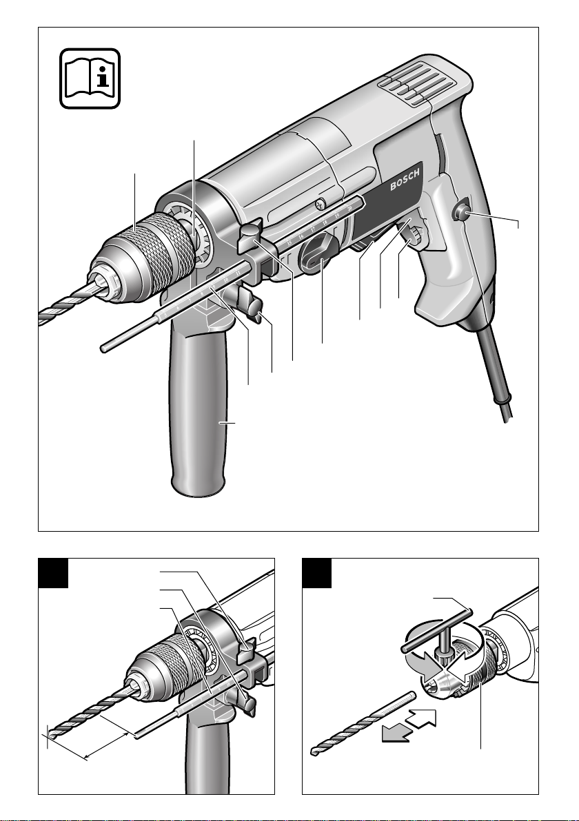
Geräteelemente
1
Schnellspannbohrfutter*
2
Schlüsselfläche
3
Feststellknopf für Ein-/Ausschalter
4
Stellrad Drehzahlvorwahl
(GBM 10-2 RE/GBM 13-2 RE)
5
Ein-/Ausschalter
6
Drehrichtungsumschalter
(GBM 10 RE/GBM 10 SRE/GBM 10-2 RE/
GBM 13-2 RE)
7
Gangwahlschalter
(GBM 10-2 RE/GBM 13-2/GBM 13-2 RE)
8
Flügelschraube für
Tiefenanschlagverstellung
9
Flügelschraube für Zusatzgriffverstellung
10
Tiefenanschlag
11
Zusatzgriff (GBM 13-2/GBM 13-2 RE)
12
Bohrfutterschlüssel*
13
Zahnkranzbohrfutter*
14
Schraubendrehereinsatz (Bit)*
15
Bohrspindel mit Innensechskant
(GBM 10 RE/GBM 10-2 RE/GBM 13-2 RE)
[Nm] 6,0/– 6,0/– 6,0/– 9,5/5,0 11,5/6,0 11,5/6,0
–
● ● ●
● ● ●
–
–
●
●
/ II / II / II / II / II / II
16
Umschalter „Bohren/Schrauben“
(GBM 10 SRE)
17
Schraubtiefenanschlag
(GBM 10 SRE)
18
Sicherungsschraube (GBM 10 RE/
GBM 10 SRE/GBM 10-2 RE/
GBM 13-2 RE)
19
Schnell-Wechseladapter (GBM 10 SRE)
20
Gurthalteclip*
*
Abgebildetes oder beschriebenes Zubehör gehört
teilweise nicht zum Lieferumfang.
Geräusch-/Vibrationsinformation
Messwerte ermittelt entsprechend EN 50 144.
Der A-bewertete Schalldruckpegel des Gerätes
beträgt typischerweise 80 dB (A).
Der Geräuschpegel beim Arbeiten kann
85 dB (A) überschreiten.
Gehörschutz tragen!
Die bewertete Beschleunigung beträgt typischerweise 3 m/s
2
.
6 • 2 609 932 285 • TMS • 31.01.03
Deutsch - 1

Zu Ihrer Sicherheit
Gefahrloses Arbeiten mit dem
Gerät ist nur möglich, wenn Sie
die Bedienungsanleitung und
die Sicherheitshinweise vollständig lesen und die darin ent-
folgen. Zusätzlich müssen die allgemeinen
Sicherheitshinweise im beigefügten Heft befolgt werden.
■
Schutzbrille tragen.
■
Bei langen Haaren Haarschutz tragen. Nur mit
eng anliegender Kleidung arbeiten.
■
Wird bei der Arbeit das Netzkabel beschädigt
oder durchtrennt, Kabel nicht berühren, sondern sofort den Netzstecker ziehen. Gerät niemals mit beschädigtem Kabel benutzen.
■
Geräte, die im Freien verwendet werden, über
einen Fehlerstrom-Schutzschalter (FI-) mit
maximal 30 mA Auslösestrom anschließen.
Nur ein für den Außenbereich zugelassenes
Verlängerungskabel verwenden.
■
Stecker nur bei ausgeschaltetem Gerät in die
Steckdose einstecken.
■
Kabel immer nach hinten vom Gerät wegführen.
■
Das Elektrowerkzeug nur an isolierten
Handgriffen anfassen, wenn das Einsatzwerkzeug eine verborgene Leitung oder
das eigene Netzkabel treffen kann.
Kontakt mit einer spannungsführenden Leitung kann Metallteile des Gerätes unter Spannung setzen und zu einem elektrischen Schlag
führen.
■
Verwenden Sie geeignete Suchgeräte, um
verborgene Versorgungsleitungen aufzuspüren, oder ziehen Sie die örtliche Versorgungsgesellschaft hinzu.
Kontakt mit Elektroleitungen kann zu Feuer
und elektrischem Schlag führen. Beschädigung einer Gasleitung kann zur Explosion
führen. Eindringen in eine Wasserleitung verursacht Sachbeschädigung oder kann einen
elektrischen Schlag verursachen.
■
Blockieren des Bohrwerkzeugs führt zu ruckartiger Reaktionskraft des Gerätes. In diesem
Fall Gerät sofort ausschalten.
■
GBM 13-2/GBM 13-2 RE:
Gerät nur mit dem Zusatzgriff
Beim Arbeiten das Gerät immer fest mit beiden
Händen halten und für einen sicheren Stand
sorgen.
haltenen Anweisungen strikt be-
Verwenden Sie Ihr
11
.
■
Sichern Sie das Werkstück.
vorrichtungen oder Schraubstock festgehaltenes Werkstück ist sicherer gehalten als mit Ihrer Hand.
■
Vorsicht beim Eindrehen langer Schrauben,
Abrutschgefahr.
■
Beim Schrauben im 1. Gang bzw. mit kleiner
Drehzahl arbeiten.
■
Gerät nur ausgeschaltet auf die Mutter/
Schraube aufsetzen.
■
Das Gerät vor dem Ablegen immer ausschalten und warten bis das Gerät zum Stillstand
gekommen ist.
■ Niemals Kindern die Benutzung des Gerätes
gestatten.
■ Bosch kann nur dann eine einwandfreie Funktion des Gerätes zusichern, wenn das für dieses Gerät vorgesehene Original-Zubehör verwendet wird.
Ein mit Spann-
Bestimmungsgemäßer Gebrauch
Das Gerät ist bestimmt zum Bohren in Holz, Metall, Keramik und Kunststoff. Geräte mit elektronischer Regelung und Rechts-/Linkslauf sind auch
geeignet zum Schrauben und Gewindeschneiden.
Zusatzgriff/Tiefenanschlag
(siehe Bild )
Der Zusatzgriff kann mit der Flügelschraube 9
rechts- oder linksseitig am Spindelhals montiert
werden.
Mit dem Tiefenanschlag 10 kann die Bohrtiefe
eingestellt werden.
Dazu die Flügelschraube für Tiefenanschlagverstellung 8 lösen, die gewünschte Bohrtiefe X einstellen und die Flügelschraube wieder festziehen.
Die Riffelung am Tiefenanschlag 10 muss nach
oben zeigen.
A
7 • 2 609 932 285 • TMS • 31.01.03
Deutsch - 2
Werkzeug einsetzen
Zahnkranzbohrfutter (siehe Bild )
Das Bohrfutter öffnen, bis das Werkzeug eingesetzt werden kann. Das Werkzeug einsetzen.
Mit dem Bohrfutterschlüssel 12 gleichmäßig in allen drei Bohrungen spannen.
Schnellspannbohrfutter (siehe Bild )
Werkzeug einsetzen
Die hintere Hülse des Schnellspannbohrfutters 1
festhalten und durch Drehen der vorderen Hülse
soweit öffnen, bis Werkzeug eingesetzt werden
kann.
Werkzeug spannen
Die hintere Hülse festhalten und die vordere
Hülse von Hand kräftig zudrehen bis kein Überrasten („klick“) mehr hörbar ist. Das Bohrfutter
wird dadurch automatisch verriegelt.
Die Verriegelung löst sich, wenn zum Entfernen
des Werkzeugs die Hülse in Gegenrichtung gedreht wird.
B
C
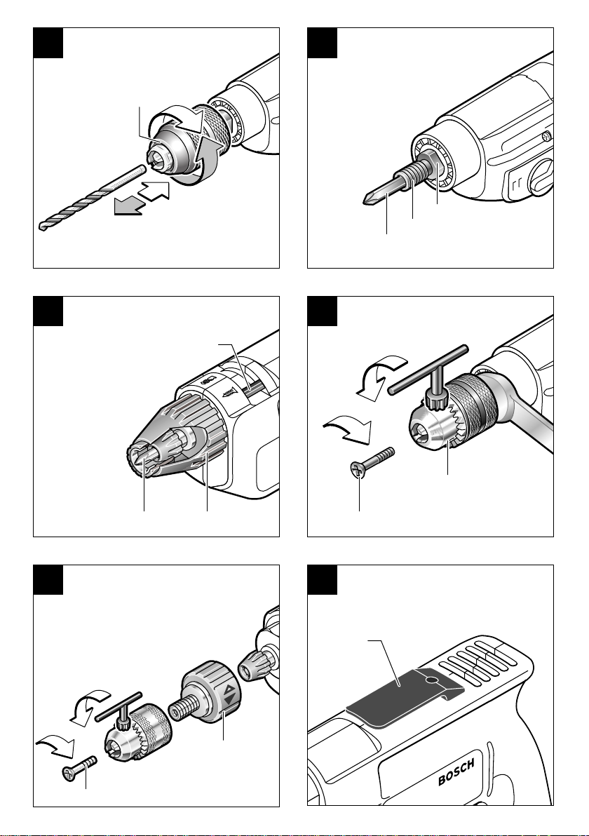
Schraubwerkzeuge (GBM 10 RE/
GBM 10-2 RE/GBM 13-2 RE–
siehe Bild )
Die Bohrspindel 15 ist zur Aufnahme von
Schraubendrehereinsätzen 14 (Bits) mit einem
Innensechskant ausgestattet. Nach Abnahme
des Bohrfutters kann der Bit direkt in die
Bohrspindel 15 eingesetzt werden, wo er durch
einen Sicherungsring gehalten wird.
D
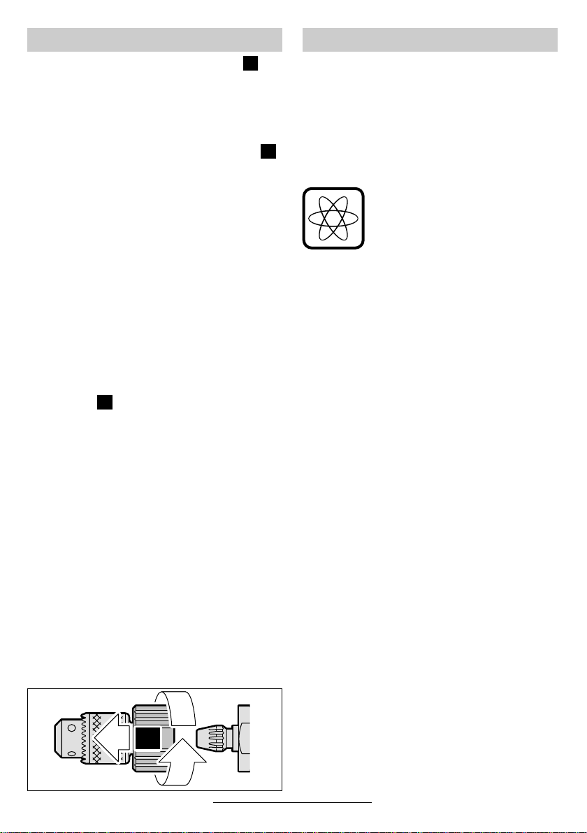
Bohrfutter-Schnellwechseladapter
(GBM 10 SRE)
Zum schnellen Umstellen von Bohren auf
Schrauben kann das Bohrfutter ohne zusätzliches Werkzeug schnell und einfach von der
Bohrspindel entfernt werden:
Zum Abnehmen des Schnell-Wechseladapters 19 das Bohrfutter festhalten und die rote Ar-
retiertaste nach vorn schieben (
Anschließend den Schnell-Wechseladapter 19
nach rechts drehen (
ter entriegelt und kann abgenommen werden.
); dadurch wird der Adap-
➋
).
➊
➊
➋
Inbetriebnahme
Netzspannung beachten: Die Spannung der
Stromquelle muss mit den Angaben auf dem
Typschild des Gerätes übereinstimmen. Mit
230 V gekennzeichnete Geräte können auch an
220 V betrieben werden.
Ein-/Ausschalten
Zur Inbetriebnahme des Gerätes den Ein-/Ausschalter 5 drücken und gedrückt halten.
GBM 10 RE/GBM 10 SRE/
GBM 10-2 RE/GBM 13-2 RE: Die
Maschine läuft je nach Druck auf
den Ein-/Ausschalter 5 mit variab-
ler Drehzahl zwischen 0 und Maximum. Leichter Druck bewirkt eine
kleine Drehzahl und macht somit
einen sanften, kontrollierten Anlauf
möglich. Das Gerät nicht so stark
belasten, dass es zum Stillstand
kommt.
Zum Feststellen den Ein-/Ausschalter 5 in ge-
drücktem Zustand mit dem Feststellknopf 3 arretieren.
Zum Ausschalten des Gerätes den Ein-/Ausschalter 5 loslassen bzw. drücken und loslassen.
Umschalten der Drehrichtung
(GBM 10 RE/GBM 10 SRE/
GBM 10-2 RE/GBM 13-2 RE)
Den Drehrichtungsumschalter 6 nur bei Stillstand betätigen.
Den Drehrichtungsumschalter 6 auf R (Rechts-
lauf) oder L (Linkslauf) stellen. (Bei betätigtem
Ein-/Ausschalter 5 ist der Drehrichtungsumschal-
ter 6 verriegelt.)
Der Linkslauf ermöglicht z. B. das Lösen von
Schrauben oder Muttern.
Mechanische Gangwahl
(GBM 10-2 RE/GBM 13-2/GBM 13-2 RE)
Mit dem Gangwahlschalter 7 können zwei Drehzahlbereiche vorgewählt werden:
Gang I: Niederer Drehzahlbereich
Gang II: Hoher Drehzahlbereich
Die Gänge können bei laufender Maschine um-
geschaltet werden. Dies sollte jedoch nicht bei
voller Belastung erfolgen.
8 • 2 609 932 285 • TMS • 31.01.03
Deutsch - 3

Drehzahlvorwahl
(GBM 10-2 RE/GBM 13-2 RE)
Mit dem Stellrad 4 lässt sich die benötigte Drehzahl (auch während des Laufes) vorwählen.
Bohren und Schrauben (GBM 10 SRE)
Mit dem Umschalter 16 kann zwischen der dauerhaften und der anpressdruckabhängigen Verbindung zwischen Antrieb und Bohrspindel gewechselt werden. Dadurch ergibt sich die Möglichkeit durch gezieltes Andrücken der Maschine
die Bohrspindel einrasten zu lassen:
Bohren
Den Umschalter 16 nach rechts schie-
ben.
Die Bohrspindel hat dauerhafte Verbindung zum
Antrieb.
Geeignet zum Bohren sowie für Einzelverschraubungen ohne Schraubtiefenanschlag 17.
Schrauben
Den Umschalter 16 nach links schieben.
Die Bohrspindel wird erst durch Anpressdruck
eingekuppelt.
Geeignet für Serienverschraubungen mit konstanter Einschraubtiefe in Verbindung mit Tiefenanschlag sowie für Einzelverschraubungen ohne
Tiefenanschlag:
Der Schraubvorgang beginnt bei ausreichend hohem Anpressdruck.
Der Umschalter 16 rastet spürbar ein und kann
bei laufender Maschine betätigt werden.
Hinweis: Beim Betätigen des Umschalters 16
kann es vorkommen, dass sich dieser in bestimmten Stellungen der Bohrspindel nicht umschalten lässt. Dazu die Bohrspindel von Hand
etwas weiterdrehen bzw. den Ein-/Ausschalter 5
kurz von Hand drücken und den Umschalter 16
erneut betätigen.
Schrauben mit Schraubtiefenanschlag
(siehe Bild )
Das Bohrfutter komplett mit dem Schnell-Wechseladapter 19 abnehmen. Das Bit (25 mm) einsetzen. Den Schraubtiefenanschlag 17 bis zum
Anschlag aufschieben. Die Schraubtiefe durch
Verdrehen des Magnetringes einstellen:
Rechtsdrehung = größere Einschraubtiefe
Linksdrehung = kleinere Einschraubtiefe
E
Bohrfutter wechseln
(siehe Bild )
F
Entfernen der Sicherungsschraube
(GBM 10 RE/GBM 10 SRE/
GBM 10-2 RE/GBM 13-2 RE)
Das Bohrfutter ist gegen das Lösen von der Bohrspindel mit der Sicherungsschraube 18 gesi-
chert. Das Bohrfutter ganz öffnen und die Sicherungsschraube 18 (Achtung Linksgewinde!)
vollständig herausschrauben.
Sitzt die Sicherungsschraube fest, Schraubendreher auf den Schraubenkopf ansetzen und
durch einen Schlag auf den Griff die Schraube lösen.
Bohrfutter abschrauben
Zahnkranzbohrfutter
GBM 10-2 RE/GBM 13-2/GBM 13-2 RE: Zum
Abschrauben des Zahnkranzbohrfutters 13, den
Gabelschlüssel (SW 17) an der Schlüsselfläche
ansetzen.
Den Bohrfutterschlüssel in eine der 3 Bohrungen
stecken und mit diesem Hebel das Bohrfutter wie
eine Schraube durch Linksdrehen lösen. Ein festsitzendes Zahnkranzbohrfutter wird durch einen
leichten Schlag auf den Bohrfutterschlüssel gelöst.
Zahnkranzbohrfutter
(GBM 10 SRE– siehe Bild )
Zum Entfernen des Zahnkranzbohrfutters den
Schnell-Wechseladapter 19 von Hand gut fest-
halten. Den Bohrfutterschlüssel 12 in eine der
3 Bohrungen stecken und mit diesem Hebel das
Bohrfutter wie eine Schraube durch Linksdrehen
lösen. Ein festsitzendes Zahnkranzbohrfutter
wird durch einen leichten Schlag auf den Bohrfutterschlüssel 12 gelöst.
Schnellspannbohrfutter
Das Sechskantwerkzeug (Innensechskantschlüssel oder Schrauberbit) in das Bohrfutter
einsetzen und mit dem freien Ende in den
Schraubstock einspannen. Den Gabelschlüssel
an die Schlüsselfläche der Bohrspindel ansetzen
und mit diesem Hebel das Bohrfutter wie eine
Schraube durch Linksdrehen lösen.
Schnellspannbohrfutter (GBM 10 SRE)
Das Sechskantwerkzeug (Innensechskantschlüssel oder Schrauberbit) in das Bohrfutter
einsetzen und mit dem freien Ende in einen
Schraubstock einspannen. Durch Linksdrehen
des Schnell-Wechseladapters 19 das Schnell-
spannbohrfutter lösen und abschrauben.
G
9 • 2 609 932 285 • TMS • 31.01.03
Deutsch - 4

Die Montage des Bohrfutters erfolgt in umgekehrter Reihenfolge.
Das Bohrfutter muss mit einem Anzugsdrehmoment von ca. 15 Nm festgezogen werden.
Tipps
Die erforderliche Drehzahl ist vom Werkstoff abhängig und kann durch praktischen Versuch ermittelt werden.
Nach längerem Arbeiten mit kleiner Drehzahl die
Maschine zur Abkühlung zirka 3 Minuten lang mit
maximaler Drehzahl im Leerlauf drehen lassen.
Bohrer schärfen
Beim Bohren in Metall nur einwandfreie geschärfte HSS-Bohrer (HSS = HochleistungsSchnell-Schnittstahl) verwenden. Entsprechende
Qualität garantiert das Bosch-Zubehör-Programm.
Mit dem Bohrerschärfgerät (siehe Zubehör) können Sie Spiralbohrer von 2,5–10 mm mühelos
schärfen.
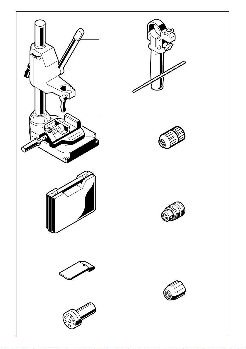
Bohrständer
Für besonders präzise Arbeiten empfiehlt es
sich, einen Bohrständer (siehe Zubehör) zu verwenden.
Wartung und Reinigung
■ Vor allen Arbeiten am Gerät Netzstecker
ziehen.
Gerät und Lüftungsschlitze stets sauber
☞
halten, um gut und sicher zu arbeiten.
Sollte das Gerät trotz sorgfältiger Herstellungsund Prüfverfahren einmal ausfallen, ist die Reparatur von einer autorisierten Kundendienststelle
für Bosch-Elektrowerkzeuge ausführen zu lassen.
Bei allen Rückfragen und Ersatzteilbestellungen
bitte unbedingt die 10-stellige Bestellnummer laut
Typenschild des Gerätes angeben.
Maschinenschraubstock
Der als Zubehör erhältliche Maschinenschraubstock ermöglicht sicheres Festspannen von
Werkstücken. Dies verhindert ein Verdrehen des
Werkstückes und dadurch entstehende Unfälle.
Gurthalteclip (siehe Bild )
Mit dem Gurthalteclip 20 kann das Gerät an ei-
nem Gurt eingehängt werden. Man hat dann
beide Hände frei und das Gerät jederzeit griffbereit.
10 • 2 609 932 285 • TMS • 31.01.03
H
Deutsch - 5

Umweltschutz Service und Kundenberater
www.powertool-portal.de, das Internetportal
für Handwerker und Heimwerker
www.ewbc.de, der Informations-Pool für Handwerk und Ausbildung
Deutschland
Rohstoffrückgewinnung statt Müllentsorgung
Gerät, Zubehör und Verpackung sollten einer
umweltgerechten Wiederverwertung zugeführt
werden.
Diese Anleitung ist aus chlorfrei gefertigtem Recycling-Papier hergestellt.
Zum sortenreinen Recycling sind Kunststoffteile
gekennzeichnet.
In Deutschland sind nicht mehr gebrauchsfähige
Geräte zum Recycling beim Handel abzugeben
oder (ausreichend frankiert) direkt einzuschicken
an:
Recyclingzentrum Elektrowerkzeuge
Osteroder Landstraße 3
37589 Kalefeld
Robert Bosch GmbH
Servicezentrum Elektrowerkzeuge
Zur Luhne 2
37589 Kalefeld
✆ Service: ....................................... 01 80 - 3 35 54 99
............................................. +49 (0) 55 53 / 20 22 37
Fax
✆ Kundenberater:...................... 01 80 - 3 33 57 99
Österreich
ABE Service GmbH
Jochen-Rindt-Straße 1
1232 Wien
✆ Service: ..................................... +43 (0)1 / 61 03 80
................................................. +43 (0)1 / 61 03 84 91
Fax
✆ Kundenberater:............. +43 (0)1 / 797 22 3066
E-Mail: abe@abe-service.co.at
Schweiz
✆ Service: ................................. +41 (0)1 / 8 47 16 16
.................................................... +41 (0)1 / 8 47 16 57
Fax
✆ Kundenberater:...... Grüne Nr. 0 800 55 11 55
11 • 2 609 932 285 • TMS • 31.01.03
Konformitätserklärung
Wir erklären in alleiniger Verantwortung, dass
dieses Produkt mit den folgenden Normen oder
normativen Dokumenten übereinstimmt:
EN 50 144 gemäß den Bestimmungen der Richtlinien 89/336/EWG, 98/37/EG.
Dr. Egbert Schneider Dr. Eckerhard Strötgen
Senior Vice President Head of Product
Engineering Certification
Robert Bosch GmbH, Geschäftsbereich Elektrowerkzeuge
Änderungen vorbehalten
Deutsch - 6

Tool Specifications
Drill GBM ... 10 10 RE 10 SRE 10-2 RE 13-2 13-2 RE
Order number 0 601 ... 135 0.. 135 5.. 137 5.. 168 5.. 169 0.. 169 5..
Rated power [W] 450 450 420 500 550 550
Output power [W] 220 220 220 270 285 285
No-load speed
1st gear [rpm] 2 000 0–2 200 0– 2 600 0 –1 150 1 000 0–1 000
2nd gear [rpm] – – – 0 –2 100 1 900 0–1 900
Rated speed
1st gear [rpm] 1 300 0–1 300 0– 1 600 0 –800 550 0–550
2nd gear [rpm] – – – 0 –1 500 1 000 0–1 000
Torque at maximum output
power (1st/2nd gear)
Stepless speed control – ● ● ● – ●
Right/left rotation – ● ● ● – ●
Chuck clamping range max. [mm] 1–10 1–10 1–10 1–10 1–13 1–13
Maximum drilling Ø
(1st/2nd gear)
Steel [mm] 10/– 10/– 10/– 10/6 13/8 13/8
Wood [mm] 25/– 25/– 25/– 25/15 32/20 32/20
Aluminium [mm] 13/– 13/– 13/– 13/8 20/12 20/12
Screw diameter, max. [mm] – – 6 – – –
Weight (without accessories).
approx.
Protection class / II / II / II / II / II / II
Please observe the order number of your machine. The trade names of the individual machines may vary.
[Nm] 6.0/– 6.0/– 6.0/– 9.5/5.0 11.5/6.0 11.5/6.0
[kg] 1.5 1.5 1.5 1.7 1.9 1.9
Machine Elements
1 Keyless chuck*
2 Flat face of nut
3 Lock-on button for On/Off switch
4 Thumbwheel for speed preselection
(GBM 10-2 RE/GBM 13-2 RE)
5 On/Off switch
6 Rotational direction switch
(GBM 10 RE/GBM 10 SRE/GBM 10-2 RE/
GBM 13-2 RE)
7 Gear selector
(GBM 10-2 RE/GBM 13-2/GBM 13-2 RE)
8 Wing bolt for depth stop adjustment
9 Winged screw for auxiliary handle
adjustment
10 Depth stop
11 Auxiliary handle (GBM 13-2/GBM 13-2 RE)
12 Chuck key*
13 Key chuck*
14 Screwdriver attachment (bit)*
12 • 2 609 932 285 • TMS • 31.01.03
English - 1
15 Drill spindle with hexagonal socket
(GBM 10 RE/GBM 10-2 RE/GBM 13-2 RE)
16 Selector switch “Drilling/Driving”
(GBM 10 SRE)
17 Screw depth stop (GBM 10 SRE)
18 Locking screw (GBM 10 RE/GBM 10 SRE/
GBM 10-2 RE/GBM 13-2 RE)
19 Quick-change adapter (GBM 10 SRE)
20 Belt clip*
* Not all of the accessories illustrated or described are
included as standard delivery.
Noise/Vibration Information
Measured values determined according to
EN 50 144.
Typically the A-weighted sound pressure level of
the product is 80 dB (A).
The noise level when working can exceed
85 dB (A).
Wear hearing protection!
The typically weighted acceleration is 3 m/s
2
.

For Your Safety
Working safely with this machine is possible only when the
operating and safety information
are read completely and the instructions contained therein are
strictly followed. In addition, the
general safety notes in the enclosed booklet
must be observed.
■ Wear safety goggles.
■ For long hair, wear hair protection. Work only
with closely fitting clothes.
■ If the mains cable is damaged or cut through
while working, do not touch the cable but immediately pull the mains plug. Never use the
machine with a damaged cable.
■ Connect machines that are used in the open
via a residual current device (RCD) with an actuating current of 30 mA maximum. Use only
extension cables that are approved for outdoor
use.
■ Insert the mains plug only when the machine is
switched off.
■ Always direct the cable to the rear away from
the machine.
■ Hold the power tool only by the insulated
gripping surfaces, when performing an operation where the cutting tool may run into
hidden wiring or its own cord.
Contact with a “live” wire will make exposed
metal parts of the tool “live” and shock the operator.
■ Use appropriate detectors to determine if
utility lines are hidden in the work area or
call the local utility company for assistance.
Contact with electric lines can lead to fire and
electric shock. Damaging a gas line can lead
to explosion. Penetrating a water line causes
property damage or may cause an electric
shock.
■ If the drilling tool jams, it will cause the power
tool to jolt. If this occurs switch the machine off
immediately.
■ GBM 13-2/GBM 13-2 RE: Operate the ma-
chine only with the auxiliary handle 11.
When working with the machine, always hold it
firmly with both hands and provide for a secure
stance.
■ Secure the workpiece. A workpiece clamped
with clamping devices or in a vice is held more
secure than by hand.
■ Be careful when screwing in long screws; danger of sliding off.
■ When screwdriving, operate in first gear as
well as with a low speed.
■ Set the machine against the screw/nut only
when switched off.
■ Always switch the machine off and wait until it
has come to a standstill before placing it down.
■ Never allow children to use the machine.
■ Bosch is only able to ensure perfect operation
of the machine if the original accessories intended for it are used.
Intended Use
The machine is intended drilling in wood, metal,
ceramic and plastic. Machines with electronic
control and right/left rotation are also suitable for
screwing and thread cutting.
Auxiliary Handle/Depth Stop
(see figure )
The auxiliary handle can be mounted on the left
or right side of the spindle collar, using the
winged screw 9.
The drilling depth can be set with the depth
stop 10.
For this, loosen wing bolt for depth stop adjustment 8, set the required drilling depth X and
tighten the wing bolt again.
The ribbing on depth stop 10 must point upwards.
A
13 • 2 609 932 285 • TMS • 31.01.03
English - 2
Inserting the Tool
Key Chuck (see figure )
Open the drill chuck until the tool can be inserted.
Insert the tool.
Clamp evenly in all three holes with the chuck
key 12.
Keyless Chuck (see figure )
Inserting the Tool
Firmly hold the rear collar of the keyless chuck 1
and open it by turning the front collar, until tool
can be inserted.
Clamping the Tool
Hold the rear collar tight and firmly tighten the
front collar by hand, until the “clicking” of the locking action is no longer heard. This automatically
locks the chuck.
The locking system releases when the sleeve is
rotated in the opposite direction, in order to remove the tool.
B
C
Screwdriver Tools (GBM 10 RE/
GBM 10-2 RE/GBM 13-2 RE–
see figure )
The drill spindle 15 is equipped with a hexagonal
socket for use with screwdriver bits 14. The bit
can be inserted directly into the drill spindle 15
when the chuck is removed. There it is retained
by a securing ring.
D
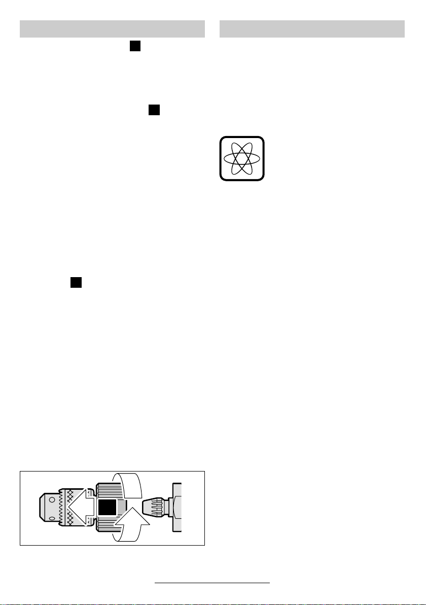
Chuck Quick-Change Adapter
(GBM 10 SRE)
For fast converting from drilling to screwdriving,
the chuck can be removed quickly and simply
from the drilling spindle without additional tools:
To remove the quick-change adapter 19, hold the
chuck firmly and push the red lock button to the
➊).
front (
Afterwards rotate the quick-change adapter 19 to
the right (
be removed.
➋); this releases the adapter and it can
➊
➋
Initial Operation
Observe correct mains voltage: The voltage of
the power source must agree with the voltage
specified on the nameplate of the machine.
Equipment marked with 230 V can also be connected to 220 V.
Switching On and Off
To start the machine, press the On/Off switch 5
and keep it depressed.
GBM 10 RE/GBM 10 SRE/
GBM 10-2 RE/GBM 13-2 RE: The
machine runs with variable speed
between 0 and maximum, depending on the pressure applied to the
On /Off switch 5. Light pressure results in a low rotational speed thus
allowing smooth, controlled starts.
Do not strain the machine so heavily that it comes to a standstill.
Lock the pushed On/Off switch 5 by pressing the
lock-on button 3.
To switch off the machine, release the On / Off
switch 5 or push and release it then.
Reversing the Rotational Direction
(GBM 10 RE/GBM 10 SRE/
GBM 10-2 RE/GBM 13-2 RE)
Operate the rotational direction switch 6 only
at a standstill.
Set the rotational direction switch 6 to R (right-
hand rotation) or L (left-hand rotation). (When the
On / Off switch 5 is actuated, the rotational direction switch 6 is locked.)
The left-hand rotation enables screws or nuts to
be unscrewed.
Gear Selection, Mechanical
(GBM 10-2 RE/GBM 13-2/GBM 13-2 RE)
Two speed ranges can be preselected with the
gear selector 7:
Speed I: Lower rpm range
Speed II: Higher rpm range
The speed can be switched during drill operation.
However, this should not be done while operating
at full load.
14 • 2 609 932 285 • TMS • 31.01.03
English - 3
Speed Preselection
(GBM 10-2 RE/GBM 13-2 RE)
The required speed can be preselected with the
thumbwheel 4 (also while running).
Drilling and Screwdriving
(GBM 10 SRE)
Switching from the permanent and the pressuredependent connection between drive and drill
spindle is possible with the selector switch 16.
Applying specific pressure with the machine will
result in an engaging of the drill spindle:
Drilling
Push selector switch 16 to the right.
The drill spindle is permanently connected to the
drive.
Suitable for drilling as well as for individual screwdriving without screw depth stop 17.
Screwdriving
Push selector switch 16 to the left.
The drill spindle engages after applying feed
pressure.
Suitable for continuous driving of screws with the
same driving depths in conjunction with the depth
stop as well as for individual screwdriving with-
out the depth stop:
The driving procedure begins with sufficient high
feed pressure.
The selector switch 16 engages noticeably and
can be actuated with the machine running.
Note: When actuating the selector switch 16 it is
possible that the switch jams or can not be
switched in certain positions of the drill spindle.
Slightly rotate the drill spindle by hand or briefly
press the On /Off switch 5, then actuate the selector switch 16 again.
Screwdriving with the Screw Depth Stop
(see figure )
Completely remove the chuck together with the
quick-change adapter 19. Insert bit (25 mm).
Push on the screw depth stop 17 to the stop. Adjust the driving depth by rotating the magnetic
ring:
Clockwise = Increased screwing depth
Counter-clockwise = Decreased screwing depth
E
Replacing the Drill Chuck
(see figure )
F
Removing locking screw
(GBM 10 RE/GBM 10 SRE/
GBM 10-2 RE/GBM 13-2 RE)
The locking screw 18 secures the drill chuck
against loosening from the drill spindle. Fully
open the chuck and completely unscrew the locking screw 18 (Note: left-handed thread!).
If the locking screw is very tight, apply the screwdriver to the head of the screw and loosen it by
giving the screwdriver handle a sharp knock.
Unscrewing the chuck
Key Chuck
GBM 10-2 RE/GBM 13-2/GBM 13-2 RE: To un-
screw key chuck 13, position the open-end spanner (size 17 mm) against the spanner flats.
Insert the chuck key into one of the three bores,
using it as a lever to loosen the drill chuck by turning in counterclockwise direction against the
spanner. A seized drill chuck is loosened with a
light blow on the chuck key.
Key Chuck (GBM 10 SRE–see figure )
To remove the key chuck hold the quick-change
adapter 19 firmly. Insert the chuck key 12 into
one of the three holes and use as a lever to
loosen the chuck by turning in counterclockwise
direction. A tight seated key chuck is loosened
with a light blow on the chuck key 12.
Keyless Chuck
Insert hexagonal tool (Allen key or screwdriver
bit) into the chuck and clamp the free end in a
vice. Position open-end spanner on key face of
drill spindle and loosen chuck in an anti-clockwise direction, as if loosening a screw.
Keyless Chuck (GBM 10 SRE)
Insert a hexagon tool (hexagon key or driving bit)
into the chuck and clamp the free end into a vice.
Loosen the keyless chuck by rotating the quickchange adapter 19 in counterclockwise direction
and remove.
The drill chuck is mounted in reverse order.
The chuck must be tightened with a
torque of approx. 15 Nm.
G
15 • 2 609 932 285 • TMS • 31.01.03
English - 4

Tips
The required speed is dependent on the material
and can be determined by practical testing.
After longer periods of working at low speed, allow the machine to cool down by running it for approx. 3 minutes at maximum speed with no load.
Sharpening Drill Bits
For drilling in metal, use only perfectly sharpened
HSS drills. The appropriate quality is guaranteed
by the Bosch accessories program.
Twist drills from 2.5–10 mm can easily be sharpened with the drill sharpener (see accessories).
Bench Stand
We recommend the use of a bench stand (see
accessories) for work where greater precision is
particularly required.
Machine Vise
The machine vise can be obtained as an accessory and clamps workpieces tightly for drilling.
This prevents the workpiece from turning and any
accidents this would cause.
Belt clip (see figure )
With the belt clip 20, the machine can be hung
onto a belt. The user has both hands free and the
machine is always at hand.
H
Maintenance and Cleaning
■ Before any work on the machine itself, pull
the mains plug.
For safe and proper working, always keep
☞
the machine and the ventilation slots clean.
If the machine should fail despite the care taken
in manufacturing and testing procedures, repair
should be carried out by an after-sales service
centre for Bosch power tools.
In all correspondence and spare parts orders,
please always include the 10-digit order number
given on the nameplate of the machine.
WARNING! Important instructions for connecting a new 3-pin plug to the 2-wire cable.
The wires in the cable are coloured according to
the following code:
strain relief
To be fitted
live = brown
neutral = blue
connect the blue or brown wire to the
Do not
earth terminal of the plug.
Important: If for any reason the moulded plug is
removed from the cable of this machine, it must
be disposed of safely.
by qualified
professional only
16 • 2 609 932 285 • TMS • 31.01.03
English - 5

Environmental Protection
Recycle raw materials instead of disposing as
waste
The machine, accessories and packaging should
be sorted for environmental-friendly recycling.
These instructions are printed on recycled paper
manufactured without chlorine.
The plastic components are labelled for categorized recycling.
Service and Customer
Assistance
Great Britain
Robert Bosch Ltd. (B.S.C.)
P.O. Box 98
Broadwater Park
North Orbital Road
Denham-Uxbridge
Middlesex UB 9 5HJ
✆ Service............................ +44 (0) 18 95 / 83 87 82
✆ Advice line .................... +44 (0) 18 95 / 83 87 91
............................................. +44 (0)18 95 / 83 87 89
Fax
New Zealand
Robert Bosch Limited
14-16 Constellation Drive
Mairangi Bay
Auckland
New Zealand
✆ ..................................................... +64 (0)9 / 47 86 158
..................................................... +64 (0)9 / 47 82 914
Fax
Ireland
Beaver Distribution Ltd.
Greenhills Road
Tallaght-Dublin 24
✆ Service................................... +353 (0)1 / 414 9400
.................................................... +353 (0)1 / 459 8030
Fax
Australia
Robert Bosch Australia Ltd.
RBAU/SPT2
1555 Centre Road
P.O. Box 66 Clayton
3168 Clayton/Victoria
✆ ............................................... +61 (0)1 / 800 804 777
............................................... +61 (0)1 / 800 819 520
Fax
www.bosch.com.au
E-Mail: CustomerSupportSPT@au.bosch.com
17 • 2 609 932 285 • TMS • 31.01.03
English - 6
Declaration of Conformity
We declare under our sole responsibility that this
product is in conformity with the following standards or standardization documents: EN 50 144
according to the provisions of the directives
89/336/EEC, 98/37/EC.
Dr. Egbert Schneider Dr. Eckerhard Strötgen
Senior Vice President Head of Product
Engineering Certification
Robert Bosch GmbH, Geschäftsbereich Elektrowerkzeuge
Subject to change without notice

Caractéristiques techniques
Perceuse GBM ... 10 10 RE 10 SRE 10-2 RE 13-2 13-2 RE
Référence 0 601 ... 135 0.. 135 5.. 137 5.. 168 5.. 169 0.. 169 5..
Puissance absorbée [W] 450 450 420 500 550 550
Puissance débitée [W] 220 220 220 270 285 285
Régime à vide
ère
1
vitesse [tr/min] 2 000 0–2 200 0 – 2 600 0–1 150 1 000 0–1 000
ème
2
vitesse [tr/min] – – – 0– 2 100 1 900 0– 1 900
Régime nominal
ère
1
vitesse [tr/min] 1 300 0–1 300 0 – 1 600 0–800 550 0 – 550
ème
2
vitesse [tr/min] – – – 0– 1 500 1 000 0– 1 000
Couple à puissance débitée
ère/2ème
max. (1
Réglage en continu de la
vitesse
Rotation à droite/à gauche – ● ● ● – ●
Fixation du mandrin de
perçage max.
Ø perçage max.
ère/2ème
(1
Acier [mm] 10/– 10/– 10/– 10/6 13/8 13/8
Bois [mm] 25/– 25/– 25/– 25/15 32/20 32/20
Aluminium [mm] 13/– 13/– 13/– 13/8 20/12 20/12
Ø des vis, max. [mm] – – 6 – – –
Poids (sans accessoires),
env.
Classe de protection / II / II / II / II / II / II
Faire attention au numéro de référence de la machine. Les désignations commerciales des différentes machines peuvent
varier.
vitesse) [Nm] 6,0/– 6,0/– 6,0/– 9,5/5,0 11,5/6,0 11,5/6,0
– ● ● ● – ●
[mm] 1–10 1–10 1–10 1–10 1–13 1–13
vitesse)
[kg] 1,5 1,5 1,5 1,7 1,9 1,9
Eléments de la machine
1 Mandrin à serrage rapide*
2 Surface de clé
3 Bouton de verrouillage de l’interrupteur
Marche/Arrêt
4 Molette de présélection de la vitesse
(GBM 10-2 RE/GBM 13-2 RE)
5 Interrupteur Marche/Arrêt
6 Commutateur du sens de rotation
(GBM 10 RE/GBM 10 SRE/GBM 10-2 RE/
GBM 13-2 RE)
7 Commutateur de vitesse
(GBM 10-2 RE/GBM 13-2/GBM 13-2 RE)
8 Vis papillon pour le réglage de la butée de
profondeur
9 Vis papillon pour réglage de la poignée
supplémentaire
10 Butée de profondeur
18 • 2 609 932 285 • TMS • 31.01.03
11 Poignée supplémentaire
(GBM 13-2/GBM 13-2 RE)
12 Clé de mandrin*
13 Mandrin à clé*
14 Embout tournevis*
15 Broche de perçage à six pans creux
(GBM 10 RE/GBM 10-2 RE/GBM 13-2 RE)
16 Commutateur « Perçage/Vissage »
(GBM 10 SRE)
17 Butée de profondeur de vissage
(GBM 10 SRE)
18 Vis de retenue (GBM 10 RE/GBM 10 SRE/
GBM 10-2 RE/GBM 13-2 RE)
19 Adaptateur à changement rapide
(GBM 10 SRE)
20 Clip de ceinture*
* Les accessoires reproduits ou décrits ne sont pas
forcément fournis avec la machine.
Français - 1

Bruits et vibrations
Valeurs de mesure obtenues conformément à la
norme européenne 50 144.
La mesure réelle (A) du niveau sonore de l’outil
est de 80 dB (A).
Le niveau sonore en fonctionnement peut dépasser 85 dB (A).
Munissez-vous d’une protection acoustique !
2
L’accélération réelle mesurée est de 3 m/s
.
Pour votre sécurité
Pour travailler sans risque avec
cet appareil, lire intégralement
au préalable les instructions
d’utilisation et les remarques
concernant la sécurité. Respec-
tions et les consignes qui y sont données.
Respecter en plus les indications générales
de sécurité se trouvant dans le cahier ci-joint.
■ Porter des lunettes de protection.
■ Les personnes portant les cheveux longs doi-
vent se munir d’un protège-cheveux. Ne travailler qu’avec des vêtements près du corps.
■ Si le câble d’alimentation électrique est endommagé ou se rompt pendant le travail, ne
pas y toucher. Retirer immédiatement la fiche
du câble d’alimentation de la prise de courant.
Ne jamais utiliser un appareil dont le cordon
d’alimentation est endommagé.
■ Monter un disjoncteur différentiel (courant de
déclenchement : 30 mA max.) en amont des
appareils utilisés en plein air. N’utiliser qu’un
câble de rallonge électrique autorisé pour les
travaux à l’extérieur.
■ Ne brancher l’appareil que si celui-ci est en position « Arrêt ».
■ Toujours ramener les câbles à l’arrière de l’appareil.
■ Ne tenir l’outil électrique que par les poignées isolées lorsqu’il y a risque que l’outil
électrique touche une conduite cachée ou
son propre câble d’alimentation.
Le contact avec une conduite sous tension
peut mettre les parties métalliques de l’appareil sous tension et provoquer ainsi une décharge électrique.
ter scrupuleusement les indica-
■ Utiliser des détecteurs appropriés afin de
déceler des conduites cachées ou consulter les entreprises d’approvisionnement locales.
Un contact avec des conduites d’électricité
peut provoquer un incendie ou une décharge
électrique. Un endommagement d’une conduite de gaz peut provoquer une explosion. La
perforation d’une conduite d’eau provoque des
dégâts matériels et peut provoquer une décharge électrique.
■ Le blocage de l’outil de perçage provoque de
fortes réactions au niveau de l’appareil. Dans
ce cas-là, arrêter immédiatement l’appareil.
■ GBM 13-2/GBM 13-2 RE : N’utilisez votre ap-
pareil qu’avec la poignée supplémentaire 11.
Pendant le travail avec cet appareil, le tenir
toujours fermement avec les deux mains.
Adopter une position stable et sûre.
■ Bloquer la pièce à travailler. Une pièce à tra-
vailler serrée par des dispositifs de serrage ou
dans un étau est fixée de manière plus sûre
que si elle est seulement tenue de la main.
■ Attention lors de la pose des vis longues : elles
peuvent glisser.
ère
■ Visser en 1
ou avec une vitesse de rotation
réduite.
■ N’appliquer l’appareil sur un écrou ou une vis
que lorsqu’il est à l’arrêt.
■ Avant de déposer l’appareil, toujours le mettre
hors fonctionnement et attendre l’arrêt total de
l’appareil.
■ Ne jamais permettre aux enfants d’utiliser cet
appareil.
■ Bosch ne peut garantir un fonctionnement impeccable que si les accessoires Bosch d’origine prévus pour cet appareil sont utilisés.
Utilisation conformément à la
destination de l’appareil
L’appareil est conçu pour le perçage dans le bois,
le métal, la céramique et les matières plastiques.
Les appareils avec réglage électronique et rotation à droite/à gauche sont également appropriés
pour le vissage et le filetage.
19 • 2 609 932 285 • TMS • 31.01.03
Français - 2
Poignée supplémentaire/Butée
de profondeur (voir figure )
La poignée supplémentaire peut être montée soit
à droite, soit à gauche du collet de la broche au
moyen de la vis papillon 9.
La butée de profondeur 10 permet de régler la
profondeur de perçage.
Pour cela, desserrer la vis papillon pour le réglage de la butée de profondeur 8, régler la profondeur de perçage X désirée et resserrer la vis
papillon.
Les cannelures de la butée de profondeur 10 doivent être tournées vers le haut.
A
Mise en place de l’outil
Mandrin à couronne dentée
(voir figure )
Ouvrir le mandrin de perçage de sorte que l’outil
puisse être monté. Monter l’outil.
A l’aide de la clé de mandrin 12, serrer de ma-
nière régulière dans les trois alésages.
B
Mandrin de perçage à serrage rapide
(voir figure )
Mise en place de l’outil
Maintenir la douille arrière du mandrin à serrage
rapide 1 puis ouvrir le mandrin en faisant tourner
la douille avant jusqu’à ce que l’ouverture soit
suffisante pour introduire l’outil.
Serrage de l’outil
Tenir la douille arrière et bien visser la douille
avant en la tournant fortement à la main jusqu’à
ce qu’il n’y ait plus de déclic perceptible. Le mandrin de perçage se trouve alors verrouillé automatiquement.
Le verrouillage peut être desserré lorsqu’on
tourne la douille en sens inverse afin d’enlever
l’outil.
C
Embouts de vissage (GBM 10 RE/
GBM 10-2 RE/GBM 13-2 RE–
voir figure )
La broche 15 est munie d’un six-pans creux pour
recevoir des embouts tournevis 14. Une fois le
mandrin retiré, l’embout peut être directement
placé dans la broche 15 où il est maintenu par un
circlip.
D
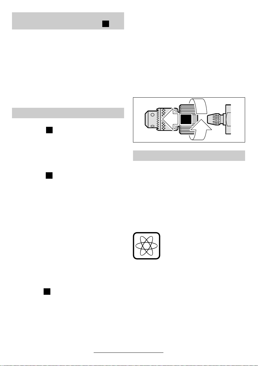
Adaptateur à changement rapide du
mandrin de perçage (GBM 10 SRE)
Pour un changement rapide et sans clé de la perceuse en visseuse, il est possible d’enlever facilement et rapidement le mandrin de perçage de
la broche de perçage :
Pour enlever l’adaptateur à changement rapide 19, bien tenir le mandrin de perçage et
pousser la touche de blocage rouge vers
➊).
l’avant (
Puis tourner l’adaptateur à changement ra-
pide 19 vers la droite (
alors déverrouillé et peut être enlevé.
➋) ; l’adaptateur se trouve
➊
➋
Mise en service
Tenir compte de la tension du secteur : La tension de la source de courant doit correspondre
aux indications figurant sur la plaque signalétique
de l’appareil. Les appareils fonctionnant sous
230 V peuvent également être utilisés sous
220 V.
Mise en fonctionnement/Arrêt
Afin de mettre l’appareil en fonctionnement,
appuyer sur l’interrupteur Marche/Arrêt 5 et le
maintenir appuyé.
GBM 10 RE/GBM 10 SRE/
GBM 10-2 RE/GBM 13-2 RE : En
fonction de la pression exercée sur
l’interrupteur Marche/Arrêt 5, l’ap-
pareil fonctionne à une vitesse
comprise entre 0 et le maximum.
Une légère pression fait tourner
l’appareil à petite vitesse, ce qui
permet un démarrage précis et en
douceur. Ne pas trop solliciter l’appareil qui risque sinon de s’arrêter.
Afin de le bloquer, bloquer l’interrupteur Marche/
Arrêt 5 dans cette position à l’aide du bouton de
blocage de fonctionnement 3.
Afin d’arrêter l’appareil, relâcher l’interrupteur
Marche/Arrêt 5 ou appuyer sur l’interrupteur et le
relâcher.
20 • 2 609 932 285 • TMS • 31.01.03
Français - 3

Inversion du sens de rotation
E
(GBM 10 RE/GBM 10 SRE/
GBM 10-2 RE/GBM 13-2 RE)
N’actionner le commutateur du sens de rotation 6 qu’à l’arrêt total de l’appareil.
Mettre le commutateur du sens de rotation 6 en
position R (rotation à droite) ou en position L (rotation à gauche). (Lorsqu’on appuie sur l’interrupteur Marche /Arrêt 5, le commutateur du sens de
rotation 6 se trouve verrouillé.)
La rotation vers la gauche permet par exemple le
desserrage d‘écrous ou de vis.
Commutation mécanique de la vitesse
(GBM 10-2 RE/GBM 13-2/ GBM 13-2 RE)
Le commutateur de vitesse 7 permet de sélec-
tionner deux plages de vitesse de rotation :
Vitesse I : Plage de vitesse réduite
Vitesse II : Plage de vitesse élevée
Il est possible de commuter sur l’autre vitesse
lorsque la perceuse est en marche. Eviter cependant une telle commutation en cas de charge
maximum.
Présélection de la vitesse de rotation
(GBM 10-2 RE/GBM 13-2 RE)
A l’aide de la molette de réglage 4, il est possible
de présélectionner la vitesse de rotation nécessaire (même pendant que l’appareil est en fonctionnement).
Perçage et vissage (GBM 10 SRE)
Au moyen du commutateur 16, il est possible de
changer entre un accouplement constant et un
accouplement dépendant de la pression exercée
entre l’entraînement et la broche de perçage. On
peut alors faire encliqueter la broche de perçage
en exerçant une pression sur la machine :
Perçage
Pousser le commutateur 16 vers la droite.
La broche de perçage est constamment reliée à
l’entraînement.
Approprié pour les travaux de perçage ainsi que
pour des vissages isolés sans butée de profondeur de vissage 17.
Vissage
Pousser le commutateur 16 vers la gau-
che.
La broche de perçage n’est accouplée que par la
pression exercée sur la machine.
Approprié pour les travaux de vissage en série
d’une profondeur de vissage toujours identique
avec butée de profondeur ainsi que pour des vissages isolés sans butée de profondeur :
Le processus de vissage démarre dès que la
pression exercée est suffisamment élevée.
Le commutateur 16 s’encliquette de manière perceptible et il peut être actionné même pendant
que l’appareil est en marche.
Remarque : Dans certaines positions de la broche de perçage, il se peut que le commutateur 16
ne puisse pas être actionné. Dans ce cas-là, tourner manuellement la broche de perçage ou appuyer brièvement sur l’interrupteur Marche/Arrêt 5 et actionner de nouveau le commutateur 16.
Vissage avec butée de profondeur de vissage
(voir figure )
Enlever complètement le mandrin de perçage
avec l’adaptateur à changement rapide 19. Monter l’embout (25 mm). Monter à fond la butée de
profondeur de vissage 17. Régler la profondeur
de vissage en tournant le porte-embout magnétique :
Rotation à droite = profondeur de vissage
Rotation à gauche = profondeur de vissage
plus grande
plus petite
Changement du mandrin
(voir figure )
F
Retirer la vis de blocage
(GBM 10 RE/GBM 10 SRE/
GBM 10-2 RE/GBM 13-2 RE)
Pour ne pas se déloger de l’unité de perçage, le
mandrin est équipé d’une vis de retenue 18.
Ouvrir complètement le mandrin et dévisser totalement la vis de retenue 18 (Attention, filetage à
gauche !).
Si la vis est bloquée, placer un tournevis sur la
tête de la vis et la débloquer en donnant un coup
sur le manche.
21 • 2 609 932 285 • TMS • 31.01.03
Français - 4

Dévissage du mandrin
Mandrin à couronne dentée
GBM 10-2 RE/GBM 13-2/GBM 13-2 RE : Pour
dévisser le mandrin à couronne dentée 13, appliquer une clé à fourche (taille 17) contre la surface
de la clé.
Introduire la clé de mandrin, faisant office de levier, dans l’un des trois orifices du mandrin et
desserrer celui-ci comme une vis, par une rotation à gauche. Si le mandrin est bloqué, il est possible de le desserrer en donnant un léger coup
sur la clé de mandrin.
Mandrin à couronne dentée
(GBM 10 SRE– voir figure )
Pour enlever le mandrin à couronne dentée, bien
tenir à la main l’adaptateur à changement rapide 19. Introduire la clé de mandrin 12 dans l’un
des trois alésages et, à l’aide de ce levier, desserrer le mandrin de perçage par un mouvement
de rotation vers la gauche, exactement comme
pour une vis. Au cas où le mandrin à couronne
dentée serait coincé, il suffit de donner un léger
coup sur la clé de mandrin 12.
Mandrin de perçage à serrage rapide
Introduire un outil hexagonal mâle (Clé mâle six
pans ou embout-tournevis hexagonal) dans le
mandrin puis bloquer l’extrémité libre dans un
étau. Appliquer la clé à fourche sur la surface
plane de la broche. La clé faisant levier, dévisser
ce mandrin comme une simple vis, en lui imprimant un rotation à gauche.
Mandrin de perçage à serrage rapide
(GBM 10 SRE)
Introduire un outil à six pans (clé mâle pour vis à
six pans creux ou embout) dans le mandrin de
perçage et serrer l’extrémité libre dans un étau.
Desserrer et dévisser le mandrin de perçage à
serrage rapide par un mouvement de rotation
vers la gauche de l’adaptateur à changement rapide 19.
G
Conseils d’utilisation
La vitesse de rotation nécessaire dépend du matériau à travailler et peut être trouvée par des essais pratiques.
Après avoir travaillé à une petite vitesse de rotation pendant une période relativement longue,
faire travailler l’appareil à vide à la vitesse de rotation maximale pendant une durée de 3 minutes
environ afin de le laisser refroidir.
Affûtage des forets
Lors de perçage dans les métaux, n’utiliser que
des forets HSS en bon état et bien affûtés
(HSS = aciers super rapides). Le programme
d’accessoires Bosch garantit la qualité des forets.
Le dispositif d’affûtage (voir « accessoires ») permet un affûtage aisé des forets hélicoïdaux de
2,5–10 mm.
Support de perçage
Lors de travaux nécessitant une grande précision, il est recommandé d’utiliser un support de
perçage (voir « accessoires »).
Etau
L’étau, disponible en tant qu’accessoire, permet
de serrer les pièces à travailler afin d’empêcher
un glissement de la pièce et de réduire ainsi les
risques d’accidents qui pourraient en résulter.
Clip de ceinture (voir figure )
Le clip de ceinture 20 permet de porter la per-
ceuse à la ceinture. Ainsi, vous avez la machine
à portée de la main, tout en étant libre de vos
mouvements.
H
Pour monter le mandrin, procéder en sens inverse.
Le mandrin de perçage doit être serré à
un couple de serrage de 15 Nm environ.
22 • 2 609 932 285 • TMS • 31.01.03
Français - 5

Nettoyage et entretien
■ Avant toute intervention sur l’appareil pro-
prement dit, toujours retirer la fiche du câble d’alimentation de la prise de courant.
Pour obtenir un travail sûr et satisfaisant,
☞
nettoyer régulièrement l’appareil ainsi que
ses ouïes de refroidissement.
Si, malgré tous les soins apportés à la fabrication
et au contrôle de l’appareil, celui-ci devait avoir
un défaut, la réparation ne doit être confiée qu’à
une station de service après-vente agréée pour
outillage Bosch.
Pour toute demande de renseignements ou commande de pièces de rechange, nous préciser impérativement le numéro de référence à dix chiffres de la machine.
Instructions de protection de
l’environnement
Récupération des matières premières plutôt
qu’élimination des déchets
Les machines, comme d’ailleurs leurs accessoires et emballages, doivent pouvoir suivre chacune une voie de recyclage appropriée.
Ce manuel d’instructions a été fabriqué à partir
d’un papier recyclé blanchi sans chlore.
Nos pièces plastiques ont ainsi été marquées en
vue d’un recyclage sélectif des différents matériaux.
Service Après-Vente
France
Information par Minitel 11
Nom : Bosch Outillage
Loc : Saint Ouen
Dépt : 93
Robert Bosch France S.A.
Service Après-vente/Outillage
B.P. 67-50, Rue Ardoin
93402 St. Ouen Cedex
✆ Service conseil client,
Numéro Vert
Belgique
Robert Bosch S.A.
After Sales Service Outillage
Rue Henri Genesse 1
1070 Bruxelles
.................................... 0 800 05 50 51
✆ ..................................................... +32 (0)2 / 525.50.29
..................................................... +32 (0)2 / 525.54.30
Fax
✆ Service conseil client..... +32 (0)2 / 525.53.07
E-Mail : Outillage.Gereedschappen@be.bosch.com
Suisse
✆ .................................................... +41 (0)1 / 8 47 16 16
.................................................... +41 (0)1 / 8 47 16 57
Fax
✆ Service conseil client,
Numéro Vert
Déclaration de conformité
Nous déclarons sous notre propre responsabilité
que ce produit est en conformité avec les normes
ou documents normalisés suivants : EN 50 144
conformément aux réglementations 89/336/CEE,
98/37/CE.
Dr. Egbert Schneider Dr. Eckerhard Strötgen
Senior Vice President Head of Product
Engineering Certification
.................................... 0 800 55 11 55
23 • 2 609 932 285 • TMS • 31.01.03
Robert Bosch GmbH, Geschäftsbereich Elektrowerkzeuge
Sous réserve de modifications
Français - 6

Características técnicas
Taladradora GBM ... 10 10 RE 10 SRE 10-2 RE 13-2 13-2 RE
Número de pedido 0 601 ... 135 0.. 135 5.. 137 5.. 168 5.. 169 0.. 169 5..
Potencia absorbida [W] 450 450 420 500 550 550
Potencia útil [W] 220 220 220 270 285 285
Revoluciones en vacío
1ª velocidad [min-1] 2 000 0–2 200 0– 2 600 0 –1 150 1 000 0–1 000
2ª velocidad [min-1] – – – 0– 2 100 1 900 0– 1 900
Revoluciones nominales
1ª velocidad [min-1] 1 300 0–1 300 0– 1 600 0 –800 550 0–550
2ª velocidad [min-1] – – – 0– 1 500 1 000 0– 1 000
Par de giro máx. a potencia
útil (1ª/2ª velocidad)
Regulación continua del
número de revoluciones
Giro a derechas/izquierdas – ● ● ● – ●
Capacidad de sujeción del
portabrocas máx.
Ø de perforación máx.
(1ª/2ª velocidad)
Acero [mm] 10/– 10/– 10/– 10/6 13/8 13/8
Madera [mm] 25/– 25/– 25/– 25/15 32/20 32/20
Aluminio [mm] 13/– 13/– 13/– 13/8 20/12 20/12
Ø de tornillo, máx. [mm] – – 6 – – –
Peso (sin accesorios), aprox. [kg] 1,5 1,5 1,5 1,7 1,9 1,9
Clase de protección / II / II / II / II / II / II
Preste atención al nº de pedido de su máquina. Las denominaciones comerciales en ciertas máquinas pueden variar.
[Nm] 6,0/– 6,0/– 6,0/– 9,5/5,0 11,5/6,0 11,5/6,0
– ● ● ● – ●
[mm] 1–10 1–10 1–10 1–10 1–13 1–13
Elementos del aparato
1 Portabrocas de sujeción rápida*
2 Entrecaras
3 Botón de enclavamiento para interruptor de
conexión/desconexión
4 Rueda preselectora de revoluciones
(GBM 10-2 RE/GBM 13-2 RE)
5 Interruptor de conexión/desconexión
6 Selector de sentido de giro
(GBM 10 RE/GBM 10 SRE/GBM 10-2 RE/
GBM 13-2 RE)
7 Selector de velocidades
(GBM 10-2 RE/GBM 13-2/GBM 13-2 RE)
8 Tornillo de mariposa para ajuste del tope de
profundidad
9 Tornillo de mariposa para ajuste de la
empuñadura adicional
10 Tope de profundidad
11 Empuñadura adicional
(GBM 13-2/GBM 13-2 RE)
12 Llave de portabrocas*
24 • 2 609 932 285 • TMS • 31.01.03
13 Portabrocas de corona dentada*
14 Lámina de destornillador (bit)*
15 Husillo de taladrar con hexágono interior
(GBM 10 RE/GBM 10-2 RE/GBM 13-2 RE)
16 Conmutador “Taladrar/Atornillar”
(GBM 10 SRE)
17 Tope de profundidad de atornillado
(GBM 10 SRE)
18 Tornillo de seguridad
(GBM 10 RE/GBM 10 SRE/GBM 10-2 RE/
GBM 13-2 RE)
19 Adaptador de cambio rápido (GBM 10 SRE)
20 Clip de sujeción al cinturón*
* Los accesorios descritos e ilustrados no correspon-
den en parte al material que se adjunta de serie.
Español - 1
 Loading...