

Bosch FSA 740 Instruction Manual
FSA 740
de
Betriebsanleitung
Fahrzeug-System-Analyse
es
Instrucciones e manejo
Analizador de sistemas de vehículo
pt
Manuais de instruçao
Análise do sistema do veículo
en
Instruction manual
Vehicle System Analysis
it
Manuale d‘istruzioni
Sistema di analisi per veicoli
fr
Instructions d‘emploi
Système d’analyse pour véhicules
sv
Bruksanvisning
Ordonssystemanalysen

2 | FSA 740
Inhaltsverzeichnis Deutsch............ 3
Contents English................... 15
Sommaire Français ................. 27
Indice Español .................... 39
Indice Italiano ..................... 51
Innehål Svenska ................... 63
Contéudo Português................ 75
Bosch Diagnostics1 689 979 895 2008-02-25|

Inhaltsverzeichnis
Inhaltsverzeichnis | FSA 740 | 3 | 3
de
1. Verwendete Symbolik 4
1.1 Testgerät 4
1.2 Dokumentation 4
2. Benutzerhinweise 5
2.1 Wichtige Hinweise 5
2.2 Sicherheitshinweise 5
2.3 Elektomagnetische Verträglichkeit (EMV) 5
2.4 Entsorgung 5
3. Produktbeschreibung 5
3.1 Verwendung 5
3.2 Lieferumfang 6
3.3 Gerätebeschreibung 6
3.3.1 Vorderansicht FSA 740 6
3.3.2 Rückansicht FSA 740 7
3.3.3 Anschlussleiste FSA 740 7
3.4 Sonderzubehör 7
4. Erstinbetriebnahme 8
4.1 Aufbau 8
4.2 Vor dem ersten Einschalten 8
4.3 Sprachauswahl von Windows 8
4.4 Inbetriebnahme KTS 530, KTS 540, KTS 570 8
6. Instandhaltung 10
6.1 Reinigung 10
6.1.1 FSA 740 10
6.1.2 Datenträger 10
6.1.3 DVD-Laufwerk 10
6.2 Ersatz- und Verschleißteile 11
7. Technische Daten 12
7.1 Messfunktionen 12
7.1.1 Motortest 12
7.1.2 Multimeter 13
7.1.3 Oszilloskop 13
7.1.4 Oszilloskop-Messfunktionen 14
7.1.5 Oszilloskop-Funktionen und
Spezifikationen 14
7.2 Signalgenerator 14
7.3 Netzteil 14
7.4 Geräuschemission 14
7.5 Maße und Gewichte 14
5. Bedienung 8
5.1 Ein-/Ausschalten 8
5.2 Diagnostics Softwareanwahl DSA 8
5.3 Startbild FSA-System-Software 8
5.4 Spracheinstellung FSA-System-Software 9
5.5 Bildschirmaufbau FSA-System-Software 9
5.6 Bedienung der FSA-System-Software 9
5.7 Drehzahlsymbole 10
5.8 ESI[tronic] 10
5.9 Software-Installation 10
Bosch Diagnostics 1 689 979 895 2008-02-25|
Bosch Diagnostics1 689 979 895 2008-02-25|
4 | FSA 740 | Verwendete Symbole
de
1. Verwendete Symbolik
1.1 Testgerät
Bosch-Testgeräte nur bei ausgeschalteter
Zündung am Fahrzeug anschließen. Vor dem
Einschalten der Zündung das Testgerät mit
der Motormasse oder Batterie (B–) verbinden.
Erklärung der aufgedruckten A-Symbolik:
Diese Betriebsanleitung und alle technischen Dokumentationen des Testgerätes und der verwendeten Komponenten beachten!
Testgerät mit Batterie (B–) oder Motormasse verbinden.1.
Zündung einschalten.2.
1.2 Dokumentation
Piktogramme in Verbindung mit den Signalwörtern
Gefahr, Warnung und Vorsicht sind Warnhinweise und
weisen immer auf eine unmittelbare oder mögliche
Gefahr für den Anwender hin.
Gefahr
Unmittelbar drohende Gefahr, die zu schweren
Körperverletzungen oder zum Tod führen
könnte.
Warnung
Möglicherweise gefährliche Situation, die zu
schweren Körperverletzungen oder zum Tod
führen könnte.
Vorsicht
Möglicherweise gefährliche Situation, die zu
leichten Körperverletzungen oder zu größeren
Sachschäden führen könnte.
Achtung ! – warnt vor möglicherweise schädlichen
Situationen, bei der das Erzeugnis, der Prüfling oder
eine Sache in der Umgebung beschädigt werden
könnte.
Zündung ausschalten.1.
Testgerät von Batterie (B–) oder Motormasse ab-2.
klemmen.
Entsorgung
Elektro- und Elektronik-Altgeräte einschließlich
Leitungen und Zubehör sowie Akku und Batterien müssen getrennt vom Hausmüll entsorgt
werden.
Zusätzlich zu den Warnhinweisen werden folgende Symbole verwendet:
Info i – Anwendungshinweise und andere nützliche
Informationen.
Einschrittige Handlungsanweisung ¶ – nur aus einem
Schritt bestehende Handlungsanweisung.
Zwischenergebnis ? – innerhalb einer Handlungsan-
weisung wird ein Zwischenergebnis sichtbar.
Endergebnis " – am Ende einer Handlungsanweisung
wird das Endergebnis sichtbar.

Bosch Diagnostics
1 689 979 895
2008-02-25|
Benutzerhinweise | FSA 740 | 5 | 5
de
2. Benutzerhinweise
2.1 Wichtige Hinweise
Wichtige Hinweise zur Vereinbarung über Urheberrecht,
Haftung und Gewährleistung, über die Benutzergruppe
und über die Verpflichtung des Unternehmens finden
Sie in der separaten Anleitung "Wichtige Hinweise und
Sicherheitshinweise" zu Bosch Test Equipment. Diese
sind vor Inbetriebnahme, Anschluss und Bedienung des
Produktes sorgfältig durchzulesen und zwingend zu
beachten.
2.2 Sicherheitshinweise
Alle Sicherheitshinweise finden Sie in der separaten
Anleitung "Wichtige Hinweise und Sicherheitshinweise"
zu Bosch Test Equipment. Diese sind vor Inbetriebnahme, Anschluss und Bedienung des Produktes sorgfältig
durchzulesen und zwingend zu beachten.
2.3 Elektomagnetische Verträglichkeit (EMV)
Dieses Produkt ist ein Erzeugnis der Klasse A nach
EN 55 022.
Dieses Produkt kann im Wohnbereich Funkstörungen i
verursachen; in diesem Fall kann vom Betreiber
verlangt werden, angemessene Maßnahmen durchzuführen.
2.4 Entsorgung
3. Produktbeschreibung
3.1 Verwendung
Die Fahrzeug-System-Analyse FSA 740 ist ein modular
aufgebautes Testgerät für die Prüftechnik in Kraftfahrzeug-Werkstätten. FSA 740 erfasst fahrzeugspezifische
Signale und leitet sie über die USB-Schnittstelle an
einen windowsbasierten PC weiter. Auf dem PC ist die
FSA-System-Software installiert. Die FSA-System-Software enthält folgende Funktionen:
Kraftfahrzeug-Identifikation. R
Einstellungen. R
Fahrzeug-System-Analyse mit R
Prüfschritte (Prüfung von Otto- und Dieselmo- $
toren).
URI. $
Signalgenerator (z. B. zur Prüfung von Sensoren). $
Komponententest (Prüfung von Fahrzeugkompo- $
nenten).
Kennlinienschreiber. $
Universal-Oszilloskop. $
Zündungsoszilloskop Primär. $
Zündungsoszilloskop Sekundär. $
Zur Beurteilung von Messergebnissen können Vergleichskurven von als gut erkannten Messkurven im
Mess-System gespeichert werden. Darüber hinaus ist
FSA 740 für eine Vernetzung mit anderen Systemen des
ASA-Werkstattnetzes vorbereitet.
Dieses Produkt unterliegt der europäischen
Richtlinie 2002/96/EG (WEEE).
Elektro- und Elektronik-Altgeräte, einschließlich Leitungen und Zubehör sowie Akku und
Batterien müssen getrennt vom Hausmüll
entsorgt werden.
Nutzen Sie zur Entsorgung die zur Verfügung 
stehenden Rückgabesysteme und Sammelsysteme.
Mit der ordnungsgemäßen Entsorgung des 
alten Geräts vermeiden Sie Umweltschäden und eine Gefährdung der persönlichen
Gesundheit.
Mit den KTS Modulen können Sie über ESI[tronic] eine
Steuergerätediagnose durchführen*).
Des Weiteren kann FSA 740 zu einem Abgasmessgerät
erweitert werden (siehe Kap. 3.4).
Zur Nutzung der fahrzeugspezifischen Prüfhinweise i
der fahrzeugspezifischen Solldaten*) sowie der
zukünftigen Erweiterung der Komponentenprüfung
ist der Abschluss eines CompacSoft[plus]-Abonnements erforderlich.
*)
Für diese Funktionen ist zusätzlich eine Freischaltung erforder-
lich. Die Freischaltung wird mit DSA durchgeführt. Die Vorgehensweise ist in der Online-Hilfe von DSA beschrieben.
*)
,
Bosch Diagnostics1 689 979 895 2008-02-25|
6 | FSA 740 | Produktbeschreibung
45977561Ko
D
IAG
2
11
10
9
3
4
5
6
8
7
BOSCH
1
de
3.2 Lieferumfang
3.3 Gerätebeschreibung
FSA 740 besteht in der Basisversion aus einem Fahrwagen mit PC, Drucker, Tastatur, Maus, Messeinheit
Benennung Bestellnummer
Fahrwagen 1 688 003 193
PC mit Betriebssystem WIN XP 1 687 023 452
Messeinheit 1 687 022 911
TFT-Monitor 1 687 023 482
Fernbedienung (mit Batterien) 1 687 246 019
USB-Maus und
Mauspad
Netzteil mit
Netzanschlussleitung
1 687 022 915
1 987 728 002
1 687 022 890
1 684 461 106
Abdeckhaube 1 685 439 025
Temperaturfühler Pkw 1 687 230 036
Triggerzange 1 687 224 957
Primär-Anschlussleitung (UNI IV) 1 684 462 211
Multi-Messleitung CH1 1 684 465 258
Multi-Messleitung CH2 1 684 465 259
Stromzange 1000A 1 687 224 968
Messwertgeber 3 x KV- (schwarz) 1 687 224 848
Messwertgeber 3 x KV+ (rot) 1 687 224 849
Stroboskop 1 687 022 767
Anschlussleitung B+/B– 1 684 460 195
Schlauchleitung 1 680 712 234
CD CompacSoft[plus] 1 687 370 275
DVD ESI[tronic] 1 987 729 601
1 987 729 605
CD (ToolsCATalogue) 1 987 729 257
DVD (Recovery - WIN XP embedded) 1 687 005 053
Zubehörsatz mit
1 687 010 153
Prüfspitzen schwarz und rot
Anschlussklemmen schwarz
Adapterleitung Klemmgeber 1 684 465 513
Anschluss-Satz für Unterdruck-Messung 1 687 010 145
PDR 371 und Netzanschlussleitung 1 687 023 435
Betriebsanleitungen 1 689 979 895
1 689 979 922
1 689 979 936
Abhängig von der bestellten Ausführung können weitere
Komponenten im Lieferumfang beiliegen (z. B. Tastatur,
Stromzange 30 A, BEA 050, RTM 430, KTS Modul).
und Fernbedienung. Der Fahrwagen bietet zusätzlichen
Raum für Funktionser weiterungen mit Abgaskomponenten BEA 050 (Otto) und RTM 430 (Diesel).
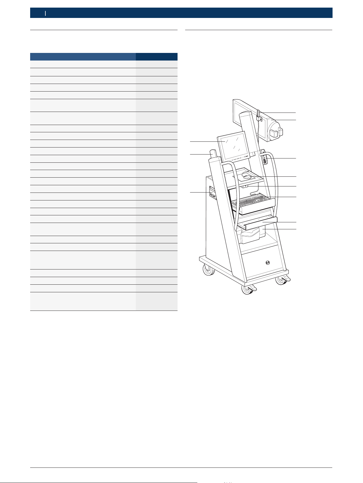
3.3.1 Vorderansicht FSA 740
Abb. 1: Vorderansicht FSA 740
1 Bluetooth-USB-Adapter
2 Messeinheit
3 KTS Modul
4 USB-Maus
5 Fernsteuerempfänger
6 Tastatur
7 Druckerabdeckung
8 Drucker (PDR 371)
9 PC mit DVD- und Disketten-Laufwerk
10 Fernbedienung
11 Monitor
*)
teilweise Sonderzubehör
*)
*)
Bosch Diagnostics 1 689 979 895 2008-02-25|
Produktbeschreibung | FSA 740 | 7 | 7
BOSCH
cal.
NO
NO
2
GF3GF2
AF1
O
2
15V DC
COM
USB
1
2
3
4
5
6
4597758/3Wo
15+ - 1
COM
KV-
KV+
USB
15V DC
CH1 CH2
D
X
45977541-Ko
1
2
3
4
5
6
7 8
9
10
11
12
13
14
de
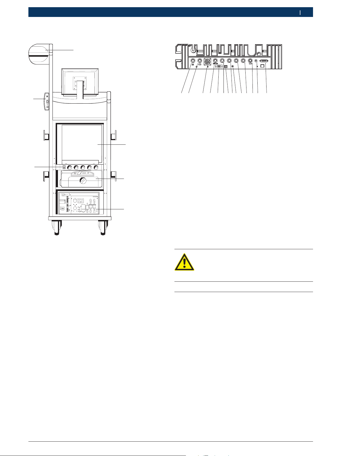
3.3.2 Rückansicht FSA 740
3.3.3 Anschlussleiste FSA 740
Abb. 3: Anschlussleiste FSA 740 (von unten)
1 Temperaturfühler
2 Anschlussleitung B+/B–
3 Anschlussleitung Kl. 1 / Kl. 15 / EST / TN/TD
4 Triggerzange oder
Adapterleitung 1 684 465 513 für Klemmgeber
5 Serielle Schnittstelle RS 232 (ohne Funktion)
6 Messwertgeber KV–
7 USB-Anschluss für Datenverbindung PC
8 Messwertgeber KV+
9 Spannungsversorgung Messeinheit (Netzteil)
10 Multi-Messleitung CH1 oder
Stromzange 30 A
11 Multi-Messleitung CH2 oder
Stromzange 30 A oder
Stromzange 1000 A
12 Stroboskop
13 Luftdruckmessung
14 Flüssigkeitsdrucksensor
*)
Bei Drehzahlmessung mit Klemmgeber muss immer die Adapt-
erleitung 1 684 465 513 zwischen Anschlussbuchse FSA 740
und den Anschlussleitungen für den Klemmgeber angeschlossen
werden.
*)
Abb. 2: Rückansicht FSA 740 ohne Rückwand
1 Messeinheit
2 PC
3 Drucker (PDR 371)
4 BEA 050
5 EIN- / AUS-Schalter mit Steckdosenleiste
6 KTS Modul
*)
teilweise Sonderzubehör
*)
*)
An den Multi-Messleitungen CH1 / CH2 können
nur Spannungen bis maximal 200 Volt gemessen werden. Niemals höhere Spannungen anlegen.
3.4 Sonderzubehör
Informationen zum Sonderzubehör, wie z. B. fahrzeugspezifische Anschlussleitungen erhalten Sie von
Ihrem Bosch Vertragshändler.
Bosch Diagnostics1 689 979 895 2008-02-25|
8 | FSA 740 | Erstinbetriebnahme
de
4. Erstinbetriebnahme
4.1 Aufbau
Verpackungen und Transportsicherungen aller gelie-1.
ferten Teile entfernen.
Sensoren an den vorgesehenen Steckplätzen der 2.
Messeinheit anschließen (siehe Abb. 3).
Stromzange 30 A und 1000 A sowie Adapterleitung
1 684 465 513 werden nur bei Bedarf angeschlossen.
Drucker in den Fahrwagen (Abb. 1; Pos. 9) stellen.3.
Netzanschlussleitung und die USB-Anschlussleitung 4.
am Drucker einstecken. Beide Leitungen liegen bereits anschlussbereit im Fahrwagen.
Die Druckerpatronen können nur bei eingeschal- i
tetem Drucker eingesetzt werden.
4.2 Vor dem ersten Einschalten
Die Spannungsversorgung erfolgt vom Lichtnetz. BEA ist
werksseitig auf 100 V $ 230 V, 50/60 Hz eingestellt. Beachten Sie bitte die entsprechenden Angaben auf dem
Aufkleber an der Geräteseite des BEA.
BEA 050 ist ab Werk auf 230 Volt eingestellt. Die Einstellung der Trafonetzspannung darf nur vom autorisierten Kundendienst vorgenommen werden. Beachten Sie
bitte hierzu die Hinweise in den Dokumentationen zu
BEA 050 und RTM 430.
5. Bedienung
5.1 Ein-/Ausschalten
Schalten Sie mit dem zentralen Netzschalter auf der Geräterückseite (siehe Abb. 2; Pos. 4) FSA 740 ein oder
aus.
Vor dem Ausschalten müssen Sie den PC über das i
Windows-Betriebssystem herunterfahren. Vor einem
erneuten Einschalten sollte der PC mindestens
60 Sekunden ausgeschaltet sein.
Beim Betrieb des FSA 740 kann es zu Störungen i
kommen, wenn PC oder andere Komponenten (z. B.
Maus, Verbindungsleitungen) eingesetzt werden, die
nicht von Bosch geliefert wurden.
5.2 Diagnostics Softwareanwahl DSA
Mit DSA können Sie:
Bosch-Anwendungen starten (auch automatisch). R
Schnittstellen-Einstellungen durchführen. R
Sprache von DSA und der Bosch-Anwendungen R
auswählen.
Software installieren. R
Freischaltung Komponententest und fahrzeugspezi- R
fische Informationen.
Kunden- und Fahrzeugdaten pflegen. R
Bosch-Anwendungen beenden. R
Weitere Informationen finden Sie in der Online-Hilfe von
DSA.
Vor der Inbetriebnahme ist sicherzustellen, dass !
die Spannung des Lichtnetzes mit der eingestellten
Spannung von BEA übereinstimmt. Wird BEA im Freien betrieben, empfehlen wir, eine Spannungsquelle
zu verwenden, die über einen FI-Schutzschalter
abgesichert ist.
4.3 Sprachauswahl von Windows
Nach dem ersten Einschalten wählen Sie über ein Menü
die Sprache des Windows-Betriebssystemes aus.
Ein nachträgliches Ändern der Sprache ist nicht vorgesehen. Sollte dies dennoch erforderlich sein, so wenden
Sie sich bitte an Ihren Bosch-Vertragshändler.
4.4 Inbetriebnahme KTS 530, KTS 540, KTS 570
Die Inbetriebnahme des KTS-Moduls ist in der Produktbeschreibung 1 689 979 987 und in der Online-Hilfe von
DDC beschrieben.
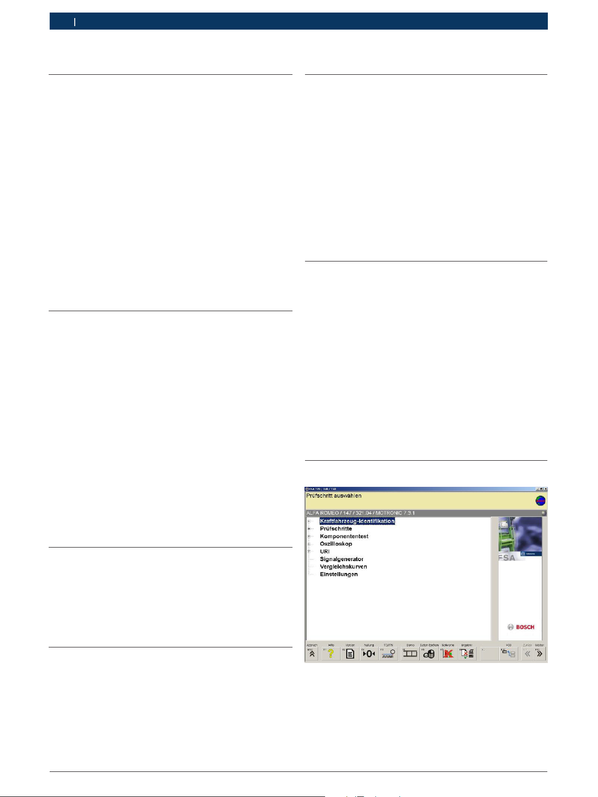
5.3 Startbild FSA-System-Software
Abb. 4: Grundbild nach dem Einschalten
Bei mehreren geöffneten Anwendungen kann es bei i
der FSA-System-Software zu Beeinträchtigungen in
der Software-Geschwindigkeit kommen.
Bosch Diagnostics 1 689 979 895 2008-02-25|
Bedienung | FSA 740 | 9 | 9
de
5.4 Spracheinstellung FSA-System-Software
Im Menü "Einstellungen" können Sie ebenfalls die
Sprache auswählen, mit der Sie am FSA 740 arbeiten
wollen. Diese Sprache gilt auch für die anderen BoschAnwendungen.
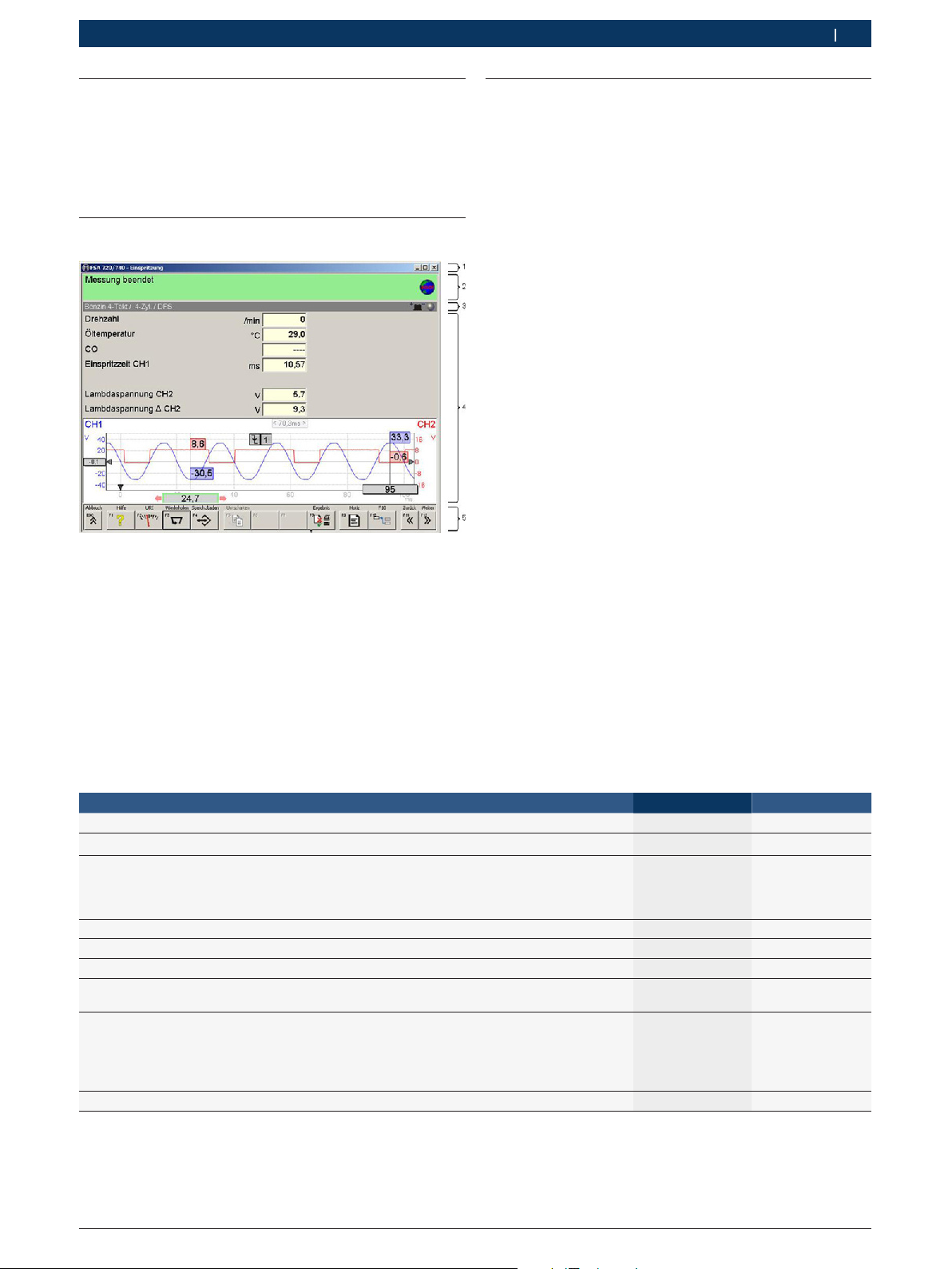
5.5 Bildschirmaufbau FSA-System-Software
Abb. 5: Funktionaler Bildschirmaufbau
1 Programm-Titelleiste wird in allen Programm-Ebenen angezeigt:
z. B. Programmname, Prüfschritt.
2 Info-Box mit Informationen und Anweisungen für den Bediener.
3 Status-Zeile mit Informationen zum Fahrzeug und zu den Sen-
soren.
4 Fensterbereich für Messergebnisse
5 Hard- und Softkeys
5.6 Bedienung der FSA-System-Software
Die Bedienung der FSA-System-Software erfolgt mit der
PC-Tastatur, mit der USB-Maus oder mit der Fernbedienung u. a. mittels Funktionstasten und Tasten.
Bitte beachten Sie, dass: i
die Tastatur immer an die PS2-Buchse des Fernbe- R
dienungsempfängers angeschlossenwerden muss.
vor Betrieb der Fernbedienung zwingend immer R
zuerst die Kanaleinstellung erfolgen muss.
Die Funktionstasten <ESC>, <F1> bis <F12> sind Hardbzw. Softkeys:
Hardkeys (<ESC>, <F1>, <F10>, <F11> und <F12>) R
sind Tasten mit festen Funktionen. Die Funktionen
dieser Tasten sind in allen Programmschritten gleich.
Softkeys (<F2> bis <F9>) sind Tasten mit wech- R
selnden Funktionen. Die Funktionen dieser Tasten
ändern sich je nach angewähltem Programmschritt.
Softkeys werden in der Online-Hilfe beschrieben.
Hard- und Softkeys, die im aktuellen Programm- R
schritt "ausgegraut" sind, sind ohne Funktion.
Hard- und Softkeys werden mittels Maus, Tastatur R
oder Fernbedienung angewählt.
Alle Informationen zur Bedienung der FSA-System-Software finden Sie in der Online-Hilfe.
Übersicht Tasten und Hardkeys von Tastatur und Fernbedienung
Funktion Fernbedienung Tastatur
Online-Hilfe zum jeweiligen Prüfschritt anzeigen. F1 <F1>
Aktuelle Messung bzw. Programmausführung beenden.
Wechsel aus jeder Bosch-Anwendung in die
Diagnostics-Software-Anwahl (DSA).
Mit der DSA können die verschiedenen Bosch-Anwendungen aufgerufen und z. B. Kundendaten eingegeben werden.
Einen Schritt zurück.
Einen Schritt weiter oder Bestätigung der Angaben.
Bewegen zu anderen Schaltflächen, Registern oder Eingabefeldern.
Bewegen innerhalb einer Schaltfläche,
eines Registers oder eines Listenfeldes.
Druckt an jeder Stelle im Programm eine Kopie der aktuellen Bild-
schirmanzeige auf dem Protokolldrucker aus.
Ausnahme Online-Hilfe:
1. Rechte Maustaste klicken.
2. “Drucken“ wählen.
Einen Schritt weiter oder Bestätigung der Angaben.
O
J
Z
V
?
D
E
<ESC>
<F10>
<F11>
<F12>
TAB-Taste
Cursor-Tasten
Druck-Taste
Enter-Taste
Bosch Diagnostics1 689 979 895 2008-02-25|
10 | FSA 740 | Instandhaltung
de
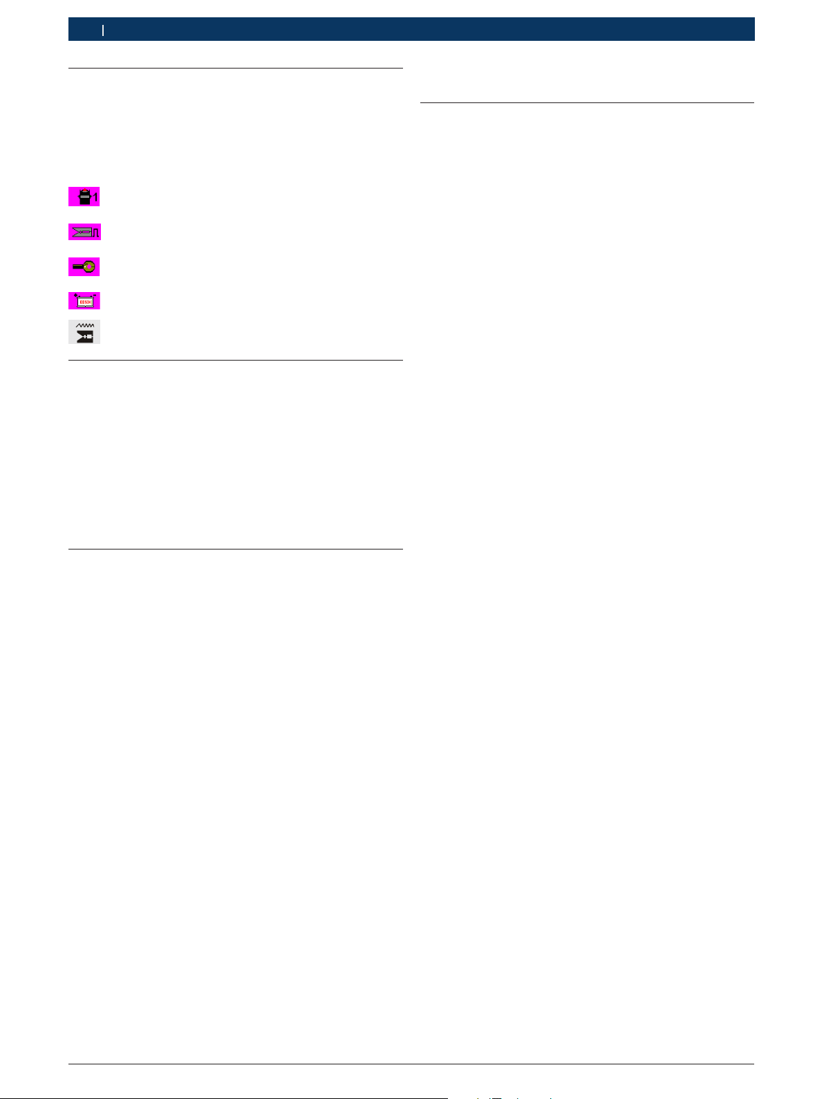
5.7 Drehzahlsymbole
Bei der Drehzahlmessung wird von der FSA-SystemSoftware die beste Drehzahl quelle automatisch ausgewählt.
Die ausgewählte Drehzahlquelle wird in der Statuszeile
am Bildschirm angezeigt.
Klemme 1 oder TD/TN
Triggerzange
Klemmgeber
Batterie-Restwelligkeit
Stromzange
5.8 ESI[tronic]
Die jeweils aktuelle Version von ESI[tronic] liegt dem i
Lieferumfang als DVD bei. Bevor Sie mit ESI[tronic]
arbeiten können, müssen Sie die Software in-
stallieren und freischalten. Die Beschreibung der
ESI[tronic]-Installation und der ESI[tronic]-Freischal-
tung finden Sie auf der "ESI[tronic] DVD 1 Diagnose
und Technik" im Verzeichnis 'DOCS\SETUP\INFO_
XXX.PDF'.
6. Instandhaltung
6.1 Reinigung
6.1.1 FSA 740
Fahrwagen, Gehäuse und LCD-Anzeige nur mit weichen
Tüchern und neutralen Reinigungsmitteln säubern. Keine scheuernden Reinigungsmittel und grobe WerkstattPutzlappen verwenden.
6.1.2 Datenträger
CD-ROM oder DVD-ROM mit einem DatenträgerReinigungskit reinigen oder wischen Sie die silberne
Seite des Datenträgers vorsichtig mit einem weichen,
fusselfreien Baumwolltuch ab. Verwenden Sie kein
Papiertuch,da dies Kratzer zur Folge haben kann.
6.1.3 DVD-Laufwerk
Das DVD-Laufwerk regelmäßig mit einem Reinigungsdatenträger für das CD-ROM- oder DVD-Laufwerk reinigen. Diese Reinigungsdatenträger sind in den meisten
Computer- oder Unterhaltungselektronikgeschäften
erhältlich.
5.9 Software-Installation
Software-Installationen über die Diagnostics Softwareanwahl (DSA) durchführen. Installationshinweise auf
der jeweiligen CD/DVD beachten.

Bosch Diagnostics 1 689 979 895 2008-02-25|
Instandhaltung | FSA 740 | 11 | 11
6.2 Ersatz- und Verschleißteile
de
Benennung Bestellnummer
PC 1 687 023 480
Monitor 1 687 023 482
Maus 1 687 022 915
Messeinrichtung 1 687 022 911
Halteblech 1 681 322 164
Netzteil 1 687 022 890
Netzanschlussleitung Netzteil
USB-Verbindungsleitung
Multi-Messleitung CH1
Multi-Messleitung CH2
Öltemperaturfühler Pkw
Strommesszange 1000 A 1 687 224 968
Strommesszange 30 A 1 687 224 969
Gummischlauch, Anschluss an Druckdose<)1 680 712 234
Anschluss-Satz Unterdruck-Messung 1 687 010 145
Triggerzange
<)
Sekundär-Anschluss-Satz "Plus" 3x, rot/+
Sekundär-AnschlussSatz "Minus" 3x,
schwarz/–
<)
Batterie-Anschlussleitung B+/B–
Primär-Anschlussleitung (UNI IV)
Stroboskop 1 687 022 767
Mess-Spitze, schwarz
Mess-Spitze, rot
Anschlussklemmen
(2 Stück), schwarz
<)
<)
Mess-Spitze schwarz
Mess-Spitze, rot
<)
Fernbedienung 1 687 201 985
Temperaturfühler Luft 1 687 230 060
Systemtester KTS 540 1 687 022 436
PDR 371 1 687 023 435
dazu USB-Verbindungsleitung
dazu Parallel-Verbindungsleitung
Adapterleitung Klemmgeber 1 684 465 513
Adapterleitung Klemmgeber 1 684 463 348
Adapterleitung Klemmgeber 1 684 463 430
Abgasadapter 1 683 350 094
Abdeckhaube 1 685 439 025
<)
<)
<)
<)
<)
1 684 461 106
1 684 465 491
1 684 460 258
1 684 460 259
1 687 230 036
1 687 224 957
<)
1 687 224 849
1 687 224 848
<)
<)
<)
1 684 460 195
1 684 462 211
1 684 485 034
1 684 485 035
1 684 480 022
<)
1 684 485 368
1 684 485 369
<)
<)
1 684 465 491
1 684 465 309
<)
Verschleißteil

Bosch Diagnostics1 689 979 895 2008-02-25|
12 | FSA 740 | Technische Daten
de
7. Technische Daten
7.1 Messfunktionen
7.1.1 Motortest
Messfunktionen Messbereiche Auflösung Sensoren
Drehzahl 450 min-1 – 6000 min
100 min-1 – 12000 min
-1
-1
10 min
10 min
-1
Anschlussleitung B+/B–
-1
Triggerzange,
Sekundär-Messwertgeber,
250 min-1 – 7200 min
100 min-1 – 500 min
-1
10 min
-1
10 min
Anschlussleitung Kl. 1
-1
Stromzange 30A
Klemmgeber Diesel,
-1
Stromzange 1000 A (Starterstrom)
Öltemperatur -20 °C – 150 °C 0,1 °C Öltemperaturfühler
U-Batterie 0 – 72,0 V 0,1 V Anschlussleitung B+/B–
U-Kl. 15 0 – 72,0 V 0,1 V Anschlussleitung Kl. 15
U-Kl. 1 0 – 20 V 50 mV Anschlussleitung Kl. 1
Zündspannung,
Funkenbrennspannung
±500 V
±50 kV
1 V
100 V
Anschlussleitung Kl. 1,
Sekundär-Messwertgeber
Funkenbrenndauer 0 – 6 ms 0,01 ms Anschlussleitung Kl. 1,
Sekundär-Messwertgeber
Relative Kompression über Starterstrom 0 – 200 Ass 0,1 A Anschlussleitung Kl. 1,
Sekundär-Messwertgeber
U-Generator Welligkeit 0 – 200 % 0,1 % Multi-Messleitung CH1
I-Starter
0 – 1000 A 0,1 A Stromzange 1000 A
I-Generator
I-Glühkerzen
I-Primär 0 – 30 A 0,1 A Stromzange 30 A
Schließwinkel 0 – 100 %
0 – 360 °
Schließzeit 0 – 50 ms 0,01 ms
Zündzeitpunkt,
0 – 60 °KW 0,1 °KW Triggerzange
0,1 %
0.1 °
0,1 ms
Anschlussleitung Kl. 1
Sekundär-Messwertgeber
Stromzange 30 A
Zündverstellung mit Stroboskop
Förderbeginn, Spitzbeginn,
0 – 60 °KW 0,1 °KW Klemmgeber
Spritzverstellung mit Stroboskop
Druck (Luft) -800 hPa – 1500 hPa 1 mbar Luftdruckfühler
Tastverhältnis t-/T 0 – 100 % 0,1 % Multi-Messleitung CH1 / CH2
Einspritzzeit 0 – 25 ms 0,01 ms Multi-Messleitung CH1 / CH2
Vorglühzeit 0 – 20 ms 0,01 ms Multi-Messleitung CH1 / CH2

Bosch Diagnostics 1 689 979 895 2008-02-25|
Technische Daten | FSA 740 | 13 | 13
de
7.1.2 Multimeter
Messfunktionen Messbereiche Auflösung Sensoren
Drehzahl wie bei Motortest
U-Batterie 0 - 72 V 0,01 V Anschlussleitung B+/B–
U-Kl. 15 0 - 72 V 0,1 V Anschlussleitung Kl. 15
U-DC/AC
min./max.
I-1000 A ±1000 A 0,1 A Stromzange 1000 A
I-30 A ±30 A 0,01 A Stromzange 30 A
Widerstand
(R-Multi 1)
Druck P-Luft 0,2 hPa – 2500 hPa 0,1 hPa Luftdruckfühler
Öltemperatur -20 °C – 150 °C 0,1 °C Öltemperaturfühler
Lufttemperatur -20 °C – 100 °C 0,1 °C Lufttemperaturfühler
Flüssigkeitsdruck 0 – 10000 hPa 10 hPa Flüssigkeitsdrucksensor
±200 mV – ±20 V
±20 V – ±200 V
0 – 1000
1 k – 10 k
10 k – 999 k
0,001 V
0,01 V
0,001
0,1
100
Multi-Messleitung CH1 / CH2
Multi-Messleitung CH1
Öldrucksensor
7.1.3 Oszilloskop
Trigger-System:
Free Run (ungetriggerter Durchlauf bei R ≥ 1 s).
Auto (Kurvenausgabe auch ohne Trigger). R
Auto-Level (wie Auto, Triggerschwelle auf Signalmitte). R
Normal (manuelle Triggerschwelle, Kurvenausgabe R
nur mit Triggerereignis).
Einzelfolge. R
Triggerflanke:
Flanke (pos. / neg. auf Signal). R
Triggerquellen:
Motor (Trigger auf Zylinder 1 ... 12 mittels Triggerzan- R
ge, Kl. 1, KV-Geber).
Extern Trigger über Kl. 1_1 Leitung oder Triggerzange. R
Multi-Messleitung CH1 / CH2. R
Pretriggeranteil:
0 bis 100 %, per Maus verschiebbar. R
Erfassungsarten:
MaxMin (Peak/Glitchdetect). R
Störpulserfassung. R
Sample (äquidistante Abtastung). R
Speicherbetriebsarten und Kurvenausgabemodis:
Roll-Mode (Einzelpunktausgabe) mit lückenloser Spei- R
cherung der Signale bei X-Ablenkungen ≥ 1 s.
Legendenmodus (Kurvenausgabe) mit lückenloser R
Speicherung der Signale bei X-Ablenkungen ≥ 1 ms.
Normalmodus mit Speicherung der letzten 50 darge- R
stellten Kurven bei X-Ablenkungen < 1 ms.
Mess-System:
8 automatische Messfunktionen R
Mittelwert $
Effektivwert $
Min $
Max $
Spitze-Spitze $
Impuls $
Tastverhältnis $
Frequenz $
Signalbereich auswählbar: gesamte Kurve oder zwi- R
schen Cursorn.
Zoom:
Wählbarer Kurvenausschnitt für horizontale und ver- R
tikale Vergrößerung.
Cursor:
Verschiebbare Cursor mit Anzeige für R
x1, x2 $
delta x $
y1 und y2 (Kanal 1) $
y1 und y2 (Kanal 2) $
Vergleichskurven:
Abspeichern, Laden, Kommentieren, Voreinstellung R
des Scope-Setups für Live-Kurven.
Speicherfunktionen. R
Vor- und Zurückblättern. R
Suchfunktionen z. B. MinMax, Tastverhältnis. R
14 | FSA 740 | Technische Daten
de
7.1.4 Oszilloskop-Messfunktionen
Messfunktionen Messbereich*) Sensoren
Sekundärspannung 5 kV – 50 kV Sekundär-
Primärspannung 20 V – 500 V Anschluss-
Spannung 200 mV – 200 V Multi-Messlei-
AC-Kopplung 200 mV – 5V Anschlussleitung B+/B–
Strom 2 A
Strom 50 A
*)
Der Messbereich ist, in Abhängigkeit der Null-Linie, positiv oder
negativ.
5 A
10 A
20 A
30 A
100 A
200 A
1000 A
Messwertgeber
leitung Kl. 1
tung CH1 / CH2
Stromzange 30 A
Stromzange 1000 A
7.1.5 Oszilloskop-Funktionen und Spezifikationen
Funktion Spezifikation
Eingangskopplung
CH1/CH2
Eingangsimpedanz
CH1/CH2 (massebezogen)
Eingangsimpedanz
CH1/CH2
(galvanisch isoliert)
Eingangsimpedanz CH2
(differenziell)
Bandbreite CH1
(galvanisch isoliert)
Bandbreite CH1 (massebezogen) > 1 MHz = 200 mV – 2 V
Bandbreite CH2 (massebezogen) > 1 MHz = 200 mV – 2 V
Bandbreite CH2
(Differenzmessung)
Bandbreite 1000 A Stromzange > 1 kHz
Bandbreite 30 A Stromzange > 50 kHz
Bandbreite Sekundär-
Messwertgeber
Bandbreite
Anschlussleitung Kl. 1
Zeitbereiche (bezogen auf
500 Abtastpunkte)
Zeitbereiche (bezogen auf
1 Abtastpunkt)
Zeitbasis Genauigkeit 0,01 %
Vertikal Genauigkeit
Gerät ohne Sensoren
Vertikalauflösung 10 bit
Speichertiefe 1 Mega Abtastwerte
Abtastrate pro Kanal 50 Ms/s
AC/DC
1 MOhm
1 MOhm (5 – 200 V)
10 MOhm (200 mV – 2 V)
4 MOhm
> 5 kHz = 200 mV – 2 V
> 25 kHz = 5 V – 200 V
> 5 MHz = 5 V – 200 V
> 5 MHz = 5 V – 200 V
> 30 kHZ
> 1 MHz
> 100 kHz (20 V)
> 1 MHz (50 V – 500 V)
10 µs – 100 s
20 ns – 200 ms
±2 % vom Messwert
±0,3 % vom Messbereich
(Offsetfehler für Bereiche
> 1 V) oder ±5 mV
(Offsetfehler für
Bereiche 200 mV – 1 V)
bzw. 50 Kurven
7.2 Signalgenerator
Funktion Spezifikation
Amplitude -10 V – 12 V
Signalformen DC, Sinus, Dreieck, Rechteck
Frequenzbereich 1 Hz – 1 kHz
Ausgangsstrom
(lastabhängig)
Impedanz ca. 60 Ohm
Symmetrie 10 % – 90 %
Kurvenerzeugung Ausgaberate bis 100000 Werte/s,
Kurzschlussfest gegen
Fremdspannung
Kurzschlussfest gegen
Fremdspannung
(Last < 10 mA) gegen Masse
30 mA – 75 mA
(Dreieck, Rechteck)
Auflösung 8 bit, Y-Vollbereich einstellbar ( bit),
Unipolar / bipolar Betrieb
< 50 V statisch
< 500 V / 1 ms dynamisch
Automatisch zugeschaltete Filter und Dämpfungs- R
glieder zur Verbesserung der Signalqualität.
Automatische Abschaltung bei Kurzschluss, Fremd- R
spannungserkennung bei Start des Signalgenerators.
7.3 Netzteil
Funktion Spezifikation
Eingangsspannung 90 VAC – 264 VAC
Eingangsfrequenz 47 Hz – 63 Hz
Ausgangsspannung 15 V
Betriebstemperatur 0 °C – 40 °C
7.4 Geräuschemission
< 70 dB(A)
7.5 Maße und Gewichte
Funktion Spezifikation
Maße H x B x T: 1785 x 680 x 670 mm
Gewicht 91 kg
Bosch Diagnostics1 689 979 895 2008-02-25|

Contents
Contents | FSA 740 | 15 | 15
en
1. Symbols Used 16
1.1 Test device 16
1.2 Documentation 16
2. User instructions 17
2.1 Important notes 17
2.2 Safety instructions 17
2.3 Electromagnetic compatibility (EMC) 17
2.4 Disposal 17
3. Product description 17
3.1 Use 17
3.2 Delivery specification 18
3.3 Description of device 18
3.3.1 FSA 740 front view 18
3.3.2 FSA 740 rear view 19
3.4 Special accessories 19
4. Initial start-up 20
4.1 Structure 20
4.2 Before starting up for the first time 20
4.3 Language selection in Windows 20
4.4 Commissioning KTS 530, KTS 540, KTS 570 20
6. Maintenance 22
6.1 Cleaning 22
6.1.1 FSA 740 22
6.1.2 Data carrier 22
6.1.3 DVD drive 22
6.2 Service parts and parts subject to wear 23
7. Technical data 24
7.1 Measuring functions 24
7.1.1 Engine test 24
7.1.2 Multimeter 25
7.1.3 Oscilloscope 25
7.1.4 Oscilloscope measuring functions 26
7.1.5 Oscilloscope functions and
specifications 26
7.2 Signal generator 26
7.3 Power pack 26
7.4 Noise emissions 26
7.5 Dimensions and weights 26
5. Operation 20
5.1 Switching the FSA 740 on/off 20
5.2 Diagnostic Software Access DSA 20
5.3 Start screen for FSA system software 20
5.4 FSA system software language configuration 21
5.5 FSA system software screen layout 21
5.6 Operating the FSA system software 21
5.7 Speed symbols 22
5.8 ESI[tronic] 22
5.9 Software installation 22
Bosch Diagnostics 1 689 979 895 2008-02-25|
Bosch Diagnostics1 689 979 895 2008-02-25|
16 | FSA 740 | Symbols Used
en
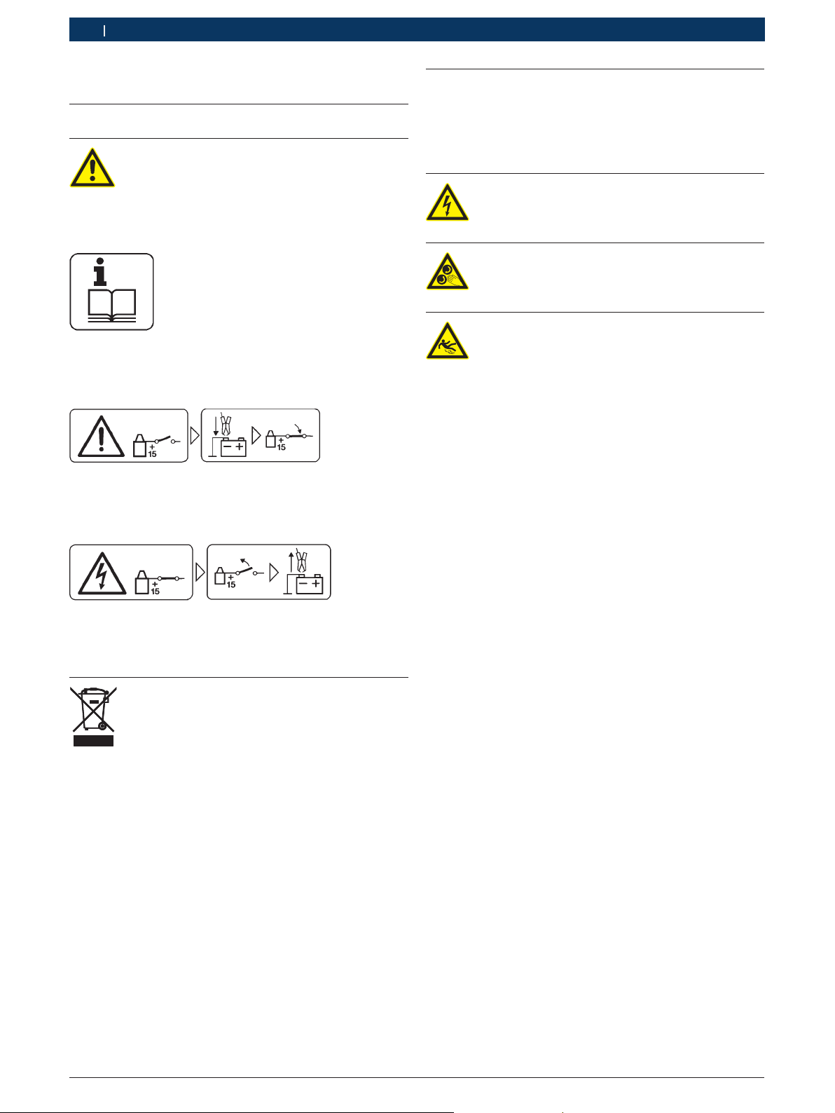
1. Symbols Used
1.1 Test device
Do not connect the test device to the vehicle
unless the ignition is switched off. Before
switching on the ignition, connect the test
device to the battery (B–) or engine ground.
Key to printed symbols:
Comply with these operating instructions and all technical documentation relating to the test device and the
components used!
Connect the test device to the battery (B–) or engine 1.
ground.
Switch the ignition on.2.
1.2 Documentation
Pictograms linked with the key words Danger, Warning
and Caution are warnings and always indicate an immediate or potential hazard to the user.
Danger
Immediate danger that could cause serious
personal injury or death.
Warning
Potentially dangerous situation that could
cause serious personal injury or death.
Caution
Potentially dangerous situation that could
cause personal injury or damage to property.
Important ! – warns of a potentially hazardous situa-
tion in which the product, the test sample or other
object in the vicinity could be damaged.
In addition to these warnings, the following symbols are
also used:
Info i – In addition to these warnings, the following
symbols are also used.
Switch the ignition off.1.
Disconnect the test device from the battery (B–) or 2.
engine ground.
Disposal
Waste electrical and electronic equipment,
including wires and accessories, power packs
and batteries must be separated from domestic waste for disposal.
Single-step procedure ¶ – instructions for a procedure
that can be completed in just one step.
Intermediate result ? – an intermediate r esult is dis-
played during a procedure.
Final result " – the final result is displayed at the end
of the procedure.

Bosch Diagnostics
1 689 979 895
2008-02-25|
User instructions | FSA 740 | 17 | 17
en
2. User instructions
2.1 Important notes
Important notes on the agreement pertaining to copyright, liability and warranty, about the user group and
obligation on the part of the contractor, are available in
the separate instructions entitled "Important notes and
safety instructions" on Bosch test equipment. These are
to be read thoroughly before using, connecting and operating the product and they must be observed.
2.2 Safety instructions
All safety instructions are available in the separate instructions "Important notes and safety instructions" on
Bosch test equipment. These are to be read thoroughly
before using, connecting and operating the product and
they must be observed.
2.3 Electromagnetic compatibility (EMC)
This product is a product of Class A as under EN 55 022.
This product can cause radio interference in the i
home; in this case the operator may be asked to
implement appropriate measures.
2.4 Disposal
This product is subject to European guidelines 2002/96/EG (WEEE).
Old electrical and electronic devices, including
cables and accessories or batteries must be
disposed of separate to household waste.
Please use the return and collection sys- 
tems in place for disposal in your area.
Damage to the environment and hazards to 
personal health are prevented by properly
disposing of old equipment.
3. Product description
3.1 Use
The FSA 740 vehicle system analysis is a modular test
device used for test engineering purposes in automotive
workshops. FSA 740 records vehicle-specific signals
and routes them via the USB interface to a Windowsbased PC. The FSA system software is installed on the
PC. The FSA System software contains the following
functions:
Vehicle identification. R
Settings. R
Vehicle system analysis with R
Test steps (testing of gasoline and diesel engines) $
URI. $
Signal generator (e.g. for testing sensors). $
Component test (testing of vehicle components). $
Characteristic recorder. $
Multipurpose oscilloscope. $
Ignition oscilloscope, primary. $
Ignition oscilloscope, secondary. $
Measurement curves which have been judged good
can be saved in the measuring system as comparison
curves. These can then be used to assess the measurement results. FSA 740 has also been designed to be
networked with other ASA workshop network systems.
The KTS modules enables you to perform control unit
diagnosis via the ESI[tronic]*). FSA 740 can also be
extended to form an exhaust gas measuring device (see
chapter 3.4).
To use the vehicle-specific test instructions i
vehicle-specific target data*) as well as future extensions to the component testing, a CompacSoft[plus]
subscription has to be taken out.
*)
, the
*)
These functions also require a release. The release is performed
with the DSA. The procedure is described in the DSA Online
Help.

Bosch Diagnostics1 689 979 895 2008-02-25|
18 | FSA 740 | Product description
45977561Ko
D
IAG
2
11
10
9
3
4
5
6
8
7
BOSCH
1
en
3.2 Delivery specification
3.3 Description of device
In its basic version, FSA 740 consists of a trolley with
PC, printer,keyboard, mouse, measuring unit and re-
Designation Order no.
Trolley 1 688 003 193
PC with WIN XP operating system 1 687 023 452
Measuring unit 1 687 022 911
TFT monitor 1 687 023 482
Remote control (with batteries) 1 687 246 019
USB mouse
and mouse pad
Power pack with
mains connection cable
1 687 022 915
1 987 728 002
1 687 022 890
1 684 461 106
Hood 1 685 439 025
Temperature sensor 1 687 230 036
Trigger clamp 1 687 224 957
Connecting cable (UNI IV) 1 684 462 211
Multi measuring cable CH1 1 684 465 258
Multi measuring cable CH2 1 684 465 259
Current clamp 1000A 1 687 224 968
Sensor 3 x KV- (black) 1 687 224 848
Sensor 3 x KV+ (red) 1 687 224 849
Stroboscope 1 687 022 767
Connecting cable B+/B– 1 684 460 195
Hose line 1 680 712 234
CD CompacSoft[plus] 1 687 370 275
DVD ESI[tronic] 1 987 729 601
1 987 729 605
CD (ToolsCATalogue) 1 987 729 257
DVD (Recovery - WIN XP embedded) 1 687 005 053
Accessory kit with
1 687 010 153
Test prods black and red
Connecting terminals black
Adapter cable clip-on sensor 1 684 465 513
Connecting set for vacuum measurement 1 687 010 145
PDR 371 and mains connection cable 1 687 023 435
Operator instructions 1 689 979 895
1 689 979 922
1 689 979 936
Depending on the model which you order, additional
components may be included in delivery (e.g. keyboard,
current clamp 30 A, BEA 050, RTM 430, KTS module).
mote control. The trolley also provides additional space
for functional extensions with exhaust gas components
BEA 050 (gasoline) and RTM 430 (diesel).
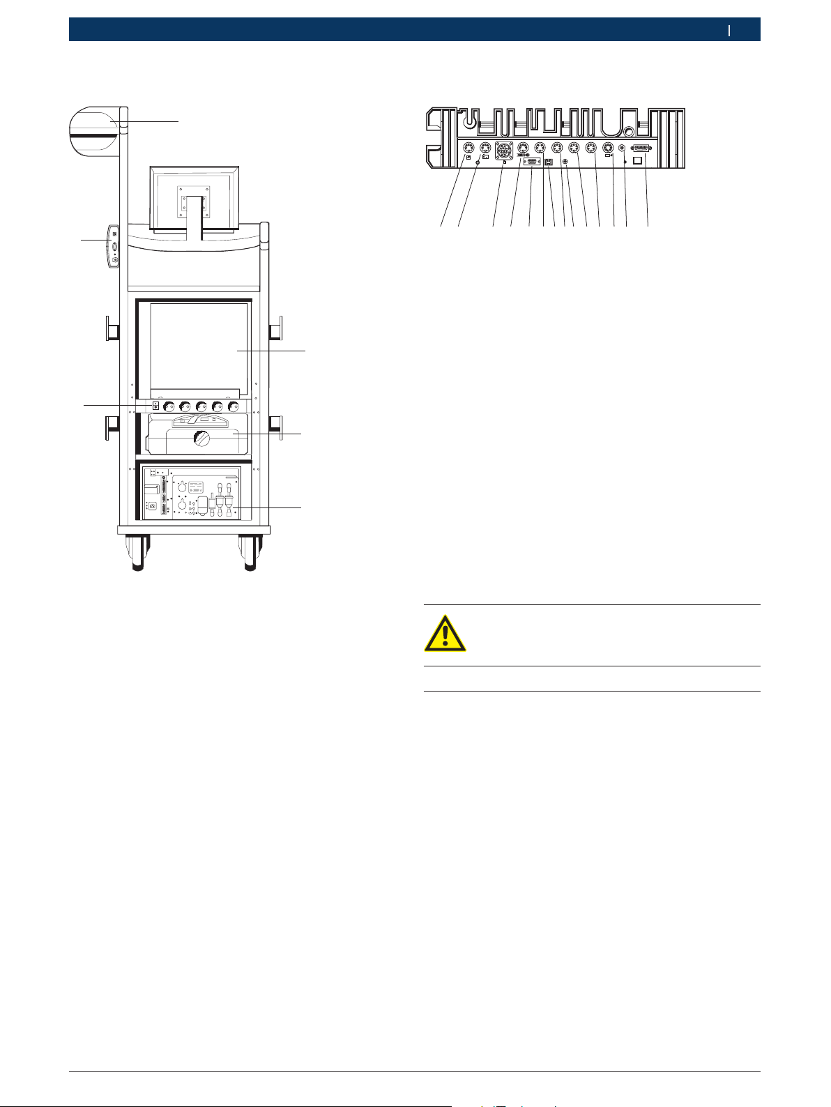
3.3.1 FSA 740 front view
Fig. 1: FSA 740 front view
1 Bluetooth USB adapter
2 Measuring unit
3 KTS modul
4 USB mouse
5 Remote control receiver
6 Keyboard
7 Printer cover
8 Printer (PDR 371)
9 PC with DVD and disk drive
10 Remote control
11 Monitor
*)
sometimes provided as special accessory
*)
*)
Bosch Diagnostics 1 689 979 895 2008-02-25|
Product description | FSA 740 | 19 | 19
BOSCH
cal.
NO
NO
2
GF3GF2
AF1
O
2
15V DC
COM
USB
1
2
3
4
5
6
4597758/3Wo
15+ - 1
COM
KV-
KV+
USB
15V DC
CH1 CH2
D
X
45977541-Ko
1
2
3
4
5
6
7 8
9
10
11
12
13
14
en
3.3.2 FSA 740 rear view
3.3.3 FSA 740 terminal strip
Fig. 3: FSA 740 terminal strip (from below)
1 Temperature sensor
2 Connecting cable B+/B–
3 Connecting cable term. 1/term. 15/EST/TN/TD
4 Trigger clamp or
adapter line 1 684 465 513 for clip-on sensor
5 RS 232 serial interface (no function)
6 Sensor KV–
7 USB connection for data connection PC
8 Sensor KV+
9 Power supply for measuring unit (power pack)
10 Multi measuring cable CH1 or
current clamp 30 A
11 Multi measuring cable CH1 or
current clamp 30 A or
current clamp 1000A
12 Stroboscope
13 Air pressure measurement
14 Liquid pressure sensor
*)
When the speed is being measured with the clip-on sensor,
adapter line 1 684 465 513 must always be connected between
plug socket FSA 740 and the connecting cables for the clip-on
sensor.
*)
Fig. 2: FSA 740 rear view without rear wall
1 Measuring unit
Only voltages up to 200 V can be measured on
the multi measuring cables CH1 / CH2. Never
apply a higher voltage.
2 PC
3 Printer (PDR 371)
4 BEA 050
5 ON / OFF switch with socket strip
6 KTS modul
*)
sometimes provided as special accessory
*)
3.4 Special accessories
*)
Information on special accessories, such as vehiclespecific connecting leads, can be obtained from your
authorized Bosch dealer.
Bosch Diagnostics1 689 979 895 2008-02-25|
20 | FSA 740 | Initial start-up
en
4. Initial start-up
4.1 Structure
Remove the packaging and the transport locks on all 1.
parts delivered.
Connect the sensors to the specified slots in the 2.
measuring unit (see Fig. 3). Only connect current
clamp 30 A and 1000 A as well as adapter line
1 684 465 513 if necessary.
Insert the printer into the trolley (Fig. 1; item 9).3.
Plug in power cord and the USB connecting cable to 4.
the printer. Both cables are provided ready for connection in the trolley.
The printer cartridges can only be used when the i
printer is switched on.
4.2 Before starting up for the first time
The voltage supply is provided via the lighting mains.
In the factory, FSA 740 has been set to 100 V - 230 V,
50/60 Hz. Read the information on the sticker on the
side of the FSA 740 carefully.
BEA 050 has been set to 230 V in the factory. The transformer mains voltage must only be adjusted by authorized service personnel. For more information, refer to
the instructions in the BEA 050 documentation.
5. Operation
5.1 Switching the FSA 740 on/off
Switch the FSA 740 on or off with the central mains
switch on the rear of the device (see Fig. 2; item 4).
Before switching off the device, shut down the PC i
using the Windows operating system. Wait at least
60 seconds before switching the device back on
again.
When operating the FSA 740, faults may occur if a i
PC or other components (e.g. mouse, connecting
cables) from suppliers other than Bosch are used.
5.2 Diagnostic Software Access DSA
With DSA, you can:
Start Bosch applications (automatically as well). R
Make interface settings. R
Select DSA and Bosch application language. R
Install software. R
Update customer and vehicle data. R
Terminate Bosch applications. R
You will find more information in the DSA online help.
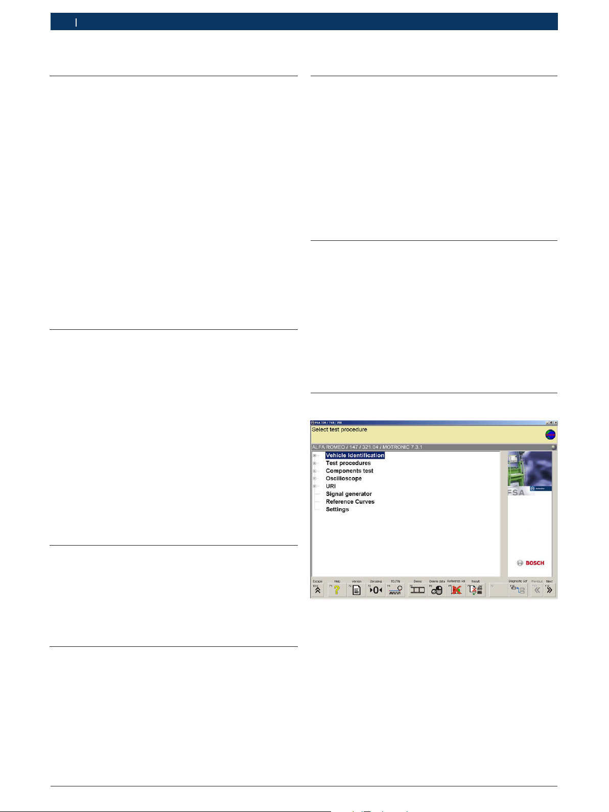
5.3 Start screen for FSA system software
Before starting up, ensure that the voltage of the !
lighting mains matches the voltage set on the
FSA 740. If the FSA 740 is operated outdoors, we
recommend using a voltage source which is fused by
means of an FI circuit breaker.
4.3 Language selection in Windows
After switching the device on the first time, select a language for the Windows operating system in a menu.
You cannot change this language at a later date. However, if this is necessary, contact your Bosch authorized
dealer.
4.4 Commissioning KTS 530, KTS 540, KTS 570
The commissioning of the KTS module is described in
the product description 1 689 979 987 and in the Online Help from DDC.
Fig. 4: Start screen after device is switched on
If several applications are open, the speed of the i
FSA system software may be impaired.
Bosch Diagnostics 1 689 979 895 2008-02-25|
Operation | FSA 740 | 21 | 21
en
5.4 FSA system software language configuration
In the "Settings" menu, you can also select the language with which you want to work in FSA 740. This
language will then be used for the other Bosch applications as well.
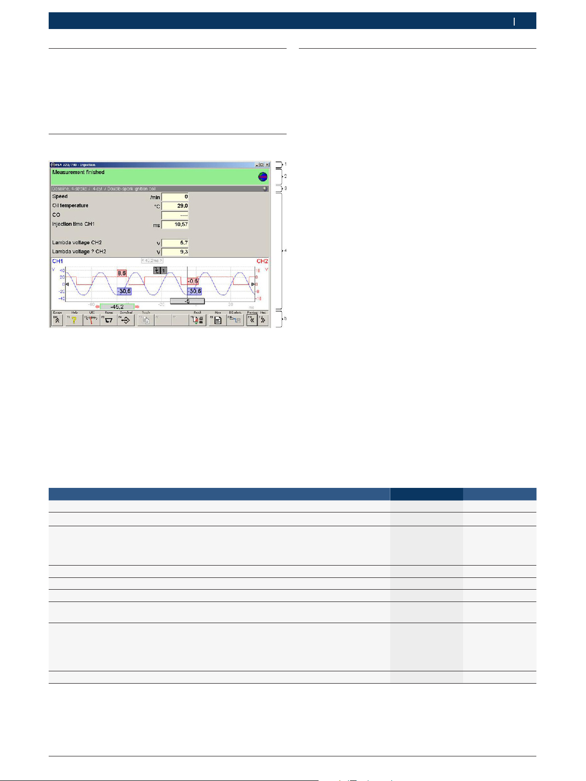
5.5 FSA system software screen layout
Fig. 5: Functional screen layout
1 Program toolbar is displayed in all program levels: e.g. program
name, test step
2 Information box with information and instructions for operator
3 Status bar with information on the vehicle and sensors
4 Window area for test results
5 Hardkeys and softkeys
5.6 Operating the FSA system software
You can operate the FSA system software via using the
function keys and buttons on the PC keyboard, the USB
mouse or the remote control.
Please note that: i
the keyboard must always be connected to R
the PS2 socket on the remote-control receiver.
the channel setting must always be configured first R
before operating the remote control.
The ESC and <F1> to <F12> function keys are hardkeys
and softkeys:
Hardkeys (<ESC>, <F1>, <F10>, <F11> und <F12>) R
are buttons with permanent functions. These keys
retain the same functions in all program steps.
Softkeys (<F2> to <F9>) are keys with alternating R
functions. The functions for these keys change depending on the selected test step.
The softkeys are described in the Online Help.
If a hardkey or softkey is “greyed out“ in a program R
step, it has no function.
You can select hardkeys and softkeys using the R
mouse, keyboard or remote control.
Information on how to operate the FSA system software
is available in the Online Help.
List of buttons and hardkeys on the keyboard and remote control
Function Remote control
Display online help for current test step. F1 <F1>
End current measurement or program.
Change from any Bosch application to the
diagnostics software selection (DSA).
You can use the DSA to call up the various Bosch applications and enter customer data, for example.
One step back.
One step forward or confirm the information.
Move to different buttons, registers or input fields.
Move within a button,
a register or a list field.
Prints out a copy of the current screen display on a pro-
tocol printer at any point in the program.
Exception: online help
1. Right click with the mouse.
2. Select “Print”.
One step forward or confirm the information.
O
J
Z
V
?
D
E
Keyboard
<ESC>
<F10>
<F11>
<F12>
TAB button
Cursor buttons
Print button
Enter button

Bosch Diagnostics1 689 979 895 2008-02-25|
22 | FSA 740 | Maintenance
en
5.7 Speed symbols
When measuring speed, the FSA system software selects the best speed source automatically.
The selected speed source is displayed in the status bar
on the screen.
Clamp 1 or TD/TN
Trigger clamp
Clip-on sensor
Battery ripple
Current clamp
5.8 ESI[tronic]
Each current version of ESI[tronic] is included in the i
delivery specification of the DVD. Before you can
operate ESI[tronic], you must first install and re-
lease the software. You will find a description of the
ESI[tronic]-installation and ESI[tronic]-connection
procedure on the "ESI[tronic] DVD 1 Diagnosis and
Technology" in the directory 'DOCS\SETUP\INFO_
XXX.PDF'.
6. Maintenance
6.1 Cleaning
6.1.1 FSA 740
The housing and the display of the FSA 740 may only
be cleaned with soft cloths and with neutral cleansing
agents. Do not use any abrasive cleansing agents or any
rough workshop cleaning cloths!
6.1.2 Data carrier
Clean the CD-ROM or DVD-ROM with a disk cleaning kit
or wipe the silver side of the disk carefully with a soft,
lint-free cotton cloth. Do not use a paper towel, as this
can lead to scratches being formed.
6.1.3 DVD drive
Clean the DVD drive regularly with a cleaning disk for
the CD-ROM or DVD drive. These cleaning disks can be
obtained from the majority of computer or consumer
electronics retailers.
5.9 Software installation
Perform software installation via the diagnostics software access (DSA). Note installation information on
each respective CD/DVD.

Bosch Diagnostics 1 689 979 895 2008-02-25|
Maintenance | FSA 740 | 23 | 23
6.2 Service parts and parts subject to
en
wear
Designation Order no.
PC 1 687 023 480
Monitor 1 687 023 482
Mouse 1 687 022 915
Measuring device 1 687 022 911
Retaining panel 1 681 322 164
Power pack 1 687 022 890
Mains connection for power pack
USB connecting cable
<)
Multi measuring cable CH1
Multi measuring cable CH2
Oil temperature sensor for cars
Current measuring clamp 1000 A 1 687 224 968
Current measuring clamp 30 A 1 687 224 969
Rubber hose,connection to actuator
Connecting set for vacuum measurement 1 687 010 145
Trigger clamp
Secondary connecting set "Po-
sitive" 3x, red/+
Secondary connecting set “Ne-
gative” 3x, black/–
<)
<)
<)
Battery connecting cable B+/B–
Primary connecting cable
(term. 1/15)
<)
Stroboscope 1 687 022 767
Test prod, black
Test prod, red
Test clamps (2 x black)
Test prod, black
Test prod, red
<)
<)
<)
<)
<)
Remote control 1 687 201 985
Air temperature sensor 1 687 230 060
System tester KTS 540 1 687 022 436
PDR 371 1 687 023 435
plus USB connecting cable
plus parallel connecting cable
Clip-on sensor adapter line 1 684 465 513
Clip-on sensor adapter line 1 684 463 348
Clip-on sensor adapter line 1 684 463 430
Exhaust gas adapter 1 683 350 094
Hood 1 685 439 025
<)
1 684 461 106
1 684 465 491
<)
<)
<)
<)
1 684 460 258
1 684 460 259
1 687 230 036
1 680 712 234
1 687 224 957
1 687 224 849
1 687 224 848
<)
1 684 460 195
1 684 462 211
1 684 485 034
1 684 485 035
1 684 480 022
1 684 485 368
1 684 485 369
<)
<)
1 684 465 491
1 684 465 309
<)
Part subject to wear

Bosch Diagnostics1 689 979 895 2008-02-25|
24 | FSA 740 | Technical data
en
7. Technical data
7.1 Measuring functions
7.1.1 Engine test
Measuring functions Measuring ranges Resolution Sensors
Speed 450 min-1 – 6000 min
100 min-1 – 12000 min
-1
-1
10 min
10 min
-1
-1
Connecting cable B+/B–
Trigger clamp,
Secondary sensor,
250 min-1 – 7200 min
100 min-1 – 500 min
-1
-1
10 min
10 min
-1
-1
Connecting cable terminal 1
Current clamp 30A
Diesel clip-on sensor,
Current clamp 1000 A
(starter current)
Oil temperature -20 °C – 150 °C 0,1 °C Oil temperature sensor
U-battery 0 – 72,0 V 0,1 V Connecting cable B+/B–
U terminal 15 0 – 72,0 V 0,1 V Connecting cable terminal 15
U terminal 1 0 – 20 V 50 mV Connecting cable terminal 1
Ignition voltage,
Spark voltage
±500 V
±50 kV
1 V
100 V
Connecting cable terminal 1,
Secondary sensor
Spark duration 0 – 6 ms 0,01 ms Connecting cable terminal 1,
Secondary sensor
Relative compression via starter current 0 – 200 Ass 0,1 A Connecting cable terminal 1,
Secondary sensor
U alternator ripple 0 – 200 % 0,1 % Multi measuring cable CH1
I starter
0 – 1000 A 0,1 A Current clamp 1000 A
I Alternator
I Spark plugs
I Primary 0 – 30 A 0,1 A Current clamp 30 A
Closing angle 0 – 100 %
0 — 360 °
Closing time 0 – 50 ms 0,01 ms
Ignition point,
0 – 60 °KW 0,1 °KW Trigger clamp
0,1 %
0.1 °
0,1 ms
Connecting cable terminal 1
Secondary sensor
Current clamp 30 A
Ignition advance with stroboscope
Start of delivery, Start of injection,
0 – 60 °KW 0,1 °KW Clip-on sensor
Injection timing
with stroboscope
Pressure (air) -800 hPa – 1500 hPa 1 mbar Air pressure sensor
Pulse-duty factor t-/T 0 – 100 % 0,1 % Multi measuring cable CH1 / CH2
Injection time 0 – 25 ms 0,01 ms Multi measuring cable CH1 / CH2
Glow time 0 – 20 ms 0,01 ms Multi measuring cable CH1 / CH2

Bosch Diagnostics 1 689 979 895 2008-02-25|
Technical data | FSA 740 | 25 | 25
en
7.1.2 Multimeter
Measuring functions Measuring ranges Resolution Sensors
Speed as for engine test
U battery 0 - 72 V 0,01 V Connecting cable B+/B–
U term. 15 0 - 72 V 0,1 V Connecting cable terminal 15
U-DC/AC
min./max.
I-1000 A ±1000 A 0,1 A Current clamp 1000 A
I-30 A ±30 A 0,01 A Current clamp 30 A
Resistance
(R Multi 1)
Pressure P-air 0,2 hPa – 2500 hPa 0,1 hPa Air pressure sensor
Oil temperature -20 °C – 150 °C 0,1 °C Oil temperature sensor
Air temperature -20 °C – 100 °C 0,1 °C Air temperature sensor
Fluid pressure 0 – 10000 hPa 10 hPa Fluid pressure sensor,
±200 mV – ±20 V
±20 V – ±200 V
0 – 1000 Ω
1 kΩ – 10 kΩ
10 kΩ – 999 kΩ
0,001 V
0,01 V
0,001 Ω
0,1 Ω
100 Ω
Multi measuring cable CH1 / CH2
Multi measuring cable CH1
Oil pressure sensor
en
7.1.3 Oscilloscope
Trigger system:
Free Run (non-triggered run at R ≥ 1 s).
Auto (curve output, also without trigger). R
Auto level (like Auto, trigger threshold at signal center). R
Normal (manual trigger threshold, curve output with R
trigger result only).
Single sequence. R
Trigger edge:
Edge (pos. / neg. on signal). R
Trigger sources:
Engine (trigger on cylinder 1 ... 12 using trigger R
clamp, clamp 1, KV sensor).
External trigger via clamp 1_1 cable or trigger clamp. R
Multi measuring cable CH1 / CH2. R
Pre-trigger percentage:
0 to 100 %, can be shifted with mouse. R
Recording modes:
MaxMin (Peak/Glitchdetect). R
Interference pulse recording. R
Sample (equidistant scanning). R
Memory operating modes and curve output modes:
Roll mode (single point display) with continuous storage R
of signals when X deflections ≥ 1 s.
Legend mode (curve display) with continuous storage of R
signals when X deflections ≥ 1 ms.
Normal mode with storage of last 50 displayed R
curves when X deflections < 1 ms.
Measuring system:
8 measuring functions. R
Average value. R
Effective value. $
Min. $
Max. $
Peek to peek. $
Pulse. $
Pulse duty factor. $
Frequency. $
Signal range selectable: entire curve or between R
cursors.
Zoom:
A curve sector can be selected for horizontal and R
vertical enlargement.
Cursor:
Various cursors with display for R
x1, x2 $
delta x $
y1 and y2 (channel 1) $
y1 and y2 (channel 2) $
Comparison curves:
Store, load, comment, pre-setting of scope setup for R
live curves.
Storage functions:
Scrolling back and forth. R
Search functions e.g. MinMax, pulse duty factor. R
26 | FSA 740 | Technical data
en
7.1.4 Oscilloscope measuring functions
Measuring functions Measuring range
Secondary voltage 5 kV – 50 kV Secondary
Primary voltage 20 V – 500 V Connecting ca-
Voltage 200 mV – 200 V Multi measuring
AC coupling 200 mV – 5V Connecting ca-
Current 2 A
Current 50 A
*)
The measuring range is positive or negative depending on the
zero line.
5 A
10 A
20 A
30 A
100 A
200 A
1000 A
*)
Sensors
sensor
ble term. 1
cable CH1 / CH2
ble B+/B–
Current
clamp 30 A
Current clamp
1000 A
7.1.5 Oscilloscope functions and specifications
Function Specification
Input coupling
CH1/CH2
Input impedance
CH1/CH2
(relative to ground)
Input impedance
CH1/CH2
(galvanically insulated)
Input impedance
CH2 (switchover)
Bandwidth CH1
(galvanically insulated)
Bandwidth CH1 (relative to ground)
Bandwidth CH2 (relative to ground)
Bandwidth CH2
(differential measurement)
Bandwidth 1000 A
current clamp
Bandwidth 30 A current clamp
Bandwidth secondary
sensor
Bandwidth connecting cable term. 1
Time ranges (relative to
500 scanning points)
Time ranges (relative
to 1 scanning point)
Time basis accuracy 0,01 %
Vertical accuracy
Device without sensors
AC/DC
1 MOhm
1 MOhm (5 — 200 V)
10 MOhm (200 mV — 2 V)
4 MOhm
> 5 kHz = 200 mV – 2 V
> 25 kHz = 5 V – 200 V
> 1 MHz = 200 mV – 2 V
> 5 MHz = 5 V – 200 V
> 1 MHz = 200 mV – 2 V
> 5 MHz = 5 V – 200 V
> 30 kHZ
> 1 kHz
> 50 kHz
> 1 MHz
> 100 kHz (20 V)
> 1 MHz (50 V – 500 V)
10 µs – 100 s
20 ns – 200 ms
±2 % of reading
±0,3 % of measuring range
(Offset error for ranges > 1 V)
or ±5 mV
(offset error for ranges
200 mV – 1 V)
Function Specification
Vertical resolution 10 bit
Memory depth 1 Mega scan values or 50 curves
Scan rate per channel 50 Ms/s
7.2 Signal generator
Function Specification
Amplitude -10 V – 12 V
Signal shapes DC, sinus, triangle, square
Frequency range 1 Hz – 1 kHz
Output current
(load-dependent)
Impedance ca. 60 Ohm
Symmetry 10 % – 90 %
Curve generation Output rate up to 100,000 values/s,
Short-circuit resistance
to interference voltage
Short-circuit resistance
to interference voltage
(load < 10 mA) to ground
30 mA – 75 mA
(triangle, square)
Resolution 8 bit,
Y-full range adjustable ( bit),
Unipolar / bipolar mode.
< 50 V static
< 500 V / 1 ms dynamic
Automatically switched filter and damping elements R
for improvement of signal quality.
Automatic cutoff at short circuit, interference voltage R
detection at start of signal generator.
7.3 Power pack
Function Specification
Input voltage: 90 VAC – 264 VAC
Input frequency 47 Hz – 63 Hz
Output voltage 15 V
Operating temperature 0 °C – 40 °C
7.4 Noise emissions
< 70 dB(A)
7.5 Dimensions and weights
Function Spezifikation
Dimensions H x B x T: 1785 x 680 x 670 mm
Weight 91 kg
Bosch Diagnostics1 689 979 895 2008-02-25|

Sommaire
Sommaire | FSA 740 | 27 | 27
frfr
1. Symboles utilisés 28
1.1 L‘appareil de test 28
1.2 Documentation 28
2. Remarques pour l‘utilisateur 29
2.1 Remarques importantes 29
2.2 Consignes de sécurité 29
2.3 Compatibilité électromagnétique (CEM) 29
2.4 Mise au rebut 29
3. Description du produit 29
3.1 Utilisation 29
3.2 Contenu de la livraison 30
3.3 Description de l’appareil 30
3.3.1 Vue de l’avant FSA 740 30
3.3.2 Vue de l’arrière FSA 740 31
3.3.3 Réglette de connexion FSA 740 31
3.4 Accessoires spéciaux 31
4. Première mise en service 32
4.1 Structure 32
4.2 Avant la première mise en marche 32
4.3 Sélection de la langue pour Windows 32
4.4 Mise en service du KTS 530, KTS 540,
KTS 570 32
6. Maintenance 34
6.1 Nettoyage 34
6.1.1 FSA 740 34
6.1.2 Supports de données 34
6.1.3 Lecteur de DVD 34
6.2 Pièces de rechange et d’usure 35
7. Caractéristiques techniques 36
7.1 Fonctions métrologiques 36
7.1.1 Test moteur 36
7.1.2 Multimètre 37
7.1.3 Oscilloscope 37
7.1.4 Fonctions métrologiques oscilloscope 38
7.1.5 Fonctions et spécifications de
l’oscilloscope 38
7.2 Générateur de signal 38
7.3 Bloc d’alimentation secteur 38
7.4 Emission de bruit 38
7.5 Dimensions et poids 38
5. Utilisation 32
5.1 Mise en marche/à l’arrêt du FSA 740 32
5.2 Sélection logiciel diagnostic DSA 32
5.3 Ecran de départ du logiciel du système FSA 32
5.4 Réglage de la langue pour le logiciel du
système FSA 33
5.5 Agencement de l’écran avec le logiciel du
système FSA 33
5.6 Utilisation du logiciel du système FSA 33
5.7 Symboles du régime 34
5.8 ESI[tronic] 34
5.9 Installation logicielle 34
Bosch Diagnostics 1 689 979 895 2008-02-25|
 Loading...