

Bosch FPM-1000-ENC, FPA-1000-V2 Operation Manual
Analog Addressable Fire Panels
FPA-1000
en Installation and Operation Guide


Analog Addressable Fire Panels Table of Contents | en 3
Table of Contents
1Safety 7
1.1 General 7
1.2 Disclaimer 7
1.2.1 Disclaimer According to the GNU General Product Licence 7
1.2.2 Disclaimer According to the GNU Library General Product Licence 8
1.3 Symbols and Notes Used 8
1.4 FCC Compliance Notice 9
2 Product Description 10
2.1 Introduction 10
2.2 Features 12
2.3 System Overview Mainboard Components 14
2.4 Plug-in Modules 15
2.5 Power Supply 16
2.6 Components Connected to the Option Bus 17
2.7 Signaling Line Circuit Devices 19
2.8 Notification Appliance Circuit Devices 23
2.9 Communicator 23
2.10 Components and Accessories 24
2.11 Related Documents 24
3 Planning Information 26
3.1 Power Supply Calculations 26
3.2 Network Wiring/Connection Considerations 26
3.2.1 Ground Fault Detection 26
3.3 Configuration and Programming Basics 27
3.3.1 Points 27
3.3.2 Advanced Point Features and Processing 28
3.3.3 Events 32
3.3.4 Zones 33
3.3.5 Special Alarm Features 37
3.3.6 Sequential Reset 38
3.3.7 Multi-combined/multi-separated Alarm Modes 38
3.3.8 External Signaling 39
3.4 Address Assignment 39
3.4.1 Option Bus Address Assignment 39
3.4.2 SLC Address Assignment 40
3.4.3 Mainboard Address Assignment 41
3.5 Reporting Requirements 42
3.6 UL 864 Standard-specific Requirements 44
3.7 NFPA Standard-specific Requirements 47
3.8 Fire Safety Considerations 48
3.8.1 Smoke Detector Layout 48
3.8.2 Installing Family Residences 48
3.8.3 Escape in the Event of Fire 49
Bosch Security Systems, Inc. Installation and Operation Guide F.01U.173.607 | 01 | 2012.08

4 en | Table of Contents Analog Addressable F ire Panels
4 Installation 50
4.1 Installation Precautions 50
4.2 Installation Considerations for UL Listed Systems 50
4.3 Parts List 51
4.4 Installing the Enclosure 51
4.5 Installing the Mainboard 55
4.6 Installing Optional Plug-in Modules 57
4.7 Wiring Requirements 59
4.7.1 Option Bus Circuit Wiring Distance 60
4.7.2 SLC Wiring Distance and Styles 61
4.7.3 Networking Card Interconnections - Distances and Styles 64
4.8 Control Panel Terminal Connections 66
4.9 Option Bus Wiring 67
4.10 NAC Wiring 68
4.11 SLC Installation 69
4.11.1 SLC Wiring 69
4.11.2 Addressing Devices 73
4.12 Mainboard Relays 74
4.13 City Tie Connections 75
4.13.1 Reverse Polarity Mode 75
4.13.2 Local Energy Mode 76
4.14 Phone Line Connections (DACT) 77
4.15 Ethernet Connection 78
4.16 Power Supply Wiring 79
4.16.1 AC Power Connection 79
4.16.3 Auxiliary Power Connection 82
4.16.4 External Power Supply 82
5 Keypad Operating and Programming 84
5.1 Panel Access 84
5.2 LCD Keypad 85
5.3 Keypad Operations 89
5.4 Authority Level and PIN Codes 91
5.5 System Normal Display 93
5.6 Off-normal Display 94
5.7 Menu Navigation and Structure 97
5.7.1 HISTORY 105
5.7.2 WALK TEST 106
5.7.3 TEST MENU 106
5.7.4 CHANGE DATE/TIME 110
5.7.5 BYPASS/UNBYPASS 110
5.7.6 PROGRAMMING 112
5.7.7 RESET LEVEL 3 PIN 130
5.7.8 REMOTE PROGRAM 131
6 Browser-based Operating and Programming 132
6.1 On-site and Off-site Access 132
6.2 Connecting FPA-1000 and the User's PC 133
6.2.1 Network connection 133
F.01U.173.607 | 01 | 2012.08 Installation and Operation Guide Bosch Security Systems, Inc.

Analog Addressable Fire Panels Table of Contents | en 5
6.2.2 Direct Connection 133
6.2.3 Dial-up Connection 135
6.3 Access the FPA-1000's Web Server from the Web Browser on the User's PC 139
6.3.1 Browser Settings 139
6.3.2 Working with Web Pages 142
6.4 Setting the Access Level for Testing and Programming 142
6.4.1 General Remarks 142
6.4.2 Switching Access Levels 142
6.4.3 Make Programming Changes Effective on the FPA-1000 143
6.4.4 Access Level Time-out 143
6.5 Overview of Graphical User Interface 144
6.6 Start Page 145
6.7 Programming 146
6.7.1 Site Data 146
6.7.2 SLC 1 and SLC 2 149
6.7.3 Mainboard 151
6.7.4 Option Bus 151
6.7.5 Reporting 153
6.7.6 Zones/Floors 154
6.7.7 Networking 155
6.8 Maintenance 155
6.8.1 Control 155
6.8.2 Testing 156
6.9 Monitoring 156
6.9.1 View Status 156
6.9.2 History 157
6.10 Utilities 157
7 Diagnostics and Troubleshooting 158
7.1 Phone Monitor Troubleshooting 158
7.2 Diagnostics Data and System Information 159
7.3 FPE-1000-SLC LED Operation 160
7.4 Power and Battery Test 160
8 Maintenance 161
8.1 Battery Maintenance 161
8.2 Fuse Replacement 161
8.3 Network Communication Reset 162
8.4 System Reset 162
9 Specifications 163
9.1 Electrical 163
9.2 Mechanical 165
9.3 Environmental 166
9.4 Panel Address Data 167
9.5 Trademarks 167
Bosch Security Systems, Inc. Installation and Operation Guide F.01U.173.607 | 01 | 2012.08

6 en | Table of Contents Analog Addressable F ire Panels
A Appendices 168
A.1 Abbreviations on the Control Panel Display 168
A.2 Default Programming 170
A.3 Compatible SLC Devices for Retrofit Projects 178
A.4 Reporting Codes 179
A.5 FPA-1000-UL Operating Instructions Sheet 185
A.6 FPA-1000-V2 Operating Instructions Sheet 187
Glossary 189
Index 192
F.01U.173.607 | 01 | 2012.08 Installation and Operation Guide Bosch Security Systems, Inc.

Analog Addressable Fire Panels Safety | en 7
1Safety
1.1 General
Before using the device, read these instructions. If you do not read and understand these
explanations, you will not be able to operate the device properly. The operating instructions
do not eliminate the need for training by authorized personnel.
Install, operate, test and maintain this device according to this Installation and Operation
Guide, NFPA 72, Local Codes and the Authority Having Jurisdiction (AHJ). Failure to follow
these procedures may cause the device not to function properly. Bosch Security Systems, Inc.
is not responsible for any devices that are improperly installed, tested or maintained.
For proper installation, read and understand NFPA 72, The National Fire Alarm Code before
installation.
The Installation and Operation Guide does not contain special information about local
requirements and safety issues. Information on such issues is provided only to the extent that
it is needed for operation of the device. Ensure that you are familiar with all safety-related
processes and regulations in your area. This also includes how to act in the event of an alarm
and the initial steps to take if a fire breaks out.
The operating instructions should always be available on site. It is a required part of the
system and must be given to the new owner if the system is ever sold.
1.2 Disclaimer
NOTICE!
Bosch Security Systems, Inc. has tested and approved the FPA-1000 Analog Addressable Fire
Panels and their associated Networking Cards including the system software. The system
must only be operated with the software included in the product delivery or with authorized
software upgrades (downloadable from the official Bosch homepage). Bosch cannot be held
responsible if devices are operated with any modified software or software from other
sources.
1.2.1 Disclaimer According to the GNU General Product Licence
NO WARRANTY
BECAUSE THE PROGRAM IS LICENSED FREE OF CHARGE, THERE IS NO WARRANTY FOR THE
PROGRAM, TO THE EXTENT PERMITTED BY APPLICABLE LAW. EXCEPT WHEN OTHERWISE
STATED IN WRITING THE COPYRIGHT HOLDERS AND/OR OTHER PARTIES PROVIDE THE
PROGRAM "AS IS" WITHOUT WARRANTY OF ANY KIND, EITHER EXPRESSED OR IMPLIED,
INCLUDING, BUT NOT LIMITED TO, THE IMPLIED WARRANTIES OF MERCHANTABILITY AND
FITNESS FOR A PARTICULAR PURPOSE. THE ENTIRE RISK AS TO THE QUALITY AND
PERFORMANCE OF THE PROGRAM IS WITH YOU. SHOULD THE PROGRAM PROVE
DEFECTIVE, YOU ASSUME THE COST OF ALL NECESSARY SERVICING, REPAIR OR
CORRECTION.
IN NO EVENT UNLESS REQUIRED BY APPLICABLE LAW OR AGREED TO IN WRITING WILL ANY
COPYRIGHT HOLDER, OR ANY OTHER PARTY WHO MAY MODIFY AND/OR REDISTRIBUTE THE
PROGRAM AS PERMITTED ABOVE, BE LIABLE TO YOU FOR DAMAGES, INCLUDING ANY
GENERAL, SPECIAL, INCIDENTAL OR CONSEQUENTIAL DAMAGES ARISING OUT OF THE USE
OR INABILITY TO USE THE PROGRAM (INCLUDING BUT NOT LIMITED TO LOSS OF DATA OR
DATA BEING RENDERED INACCURATE OR LOSSES SUSTAINED BY YOU OR THIRD PARTIES
OR A FAILURE OF THE PROGRAM TO OPERATE WITH ANY OTHER PROGRAMS), EVEN IF SUCH
HOLDER OR OTHER PARTY HAS BEEN ADVISED OF THE POSSIBILITY OF SUCH DAMAGES.
Bosch Security Systems, Inc. Installation and Operation Guide F.01U.173.607 | 01 | 2012.08
8 en | Safety Analog Addressable Fire Panels
1.2.2 Disclaimer According to the GNU Library General Product Licence
NO WARRANTY
BECAUSE THE LIBRARY IS LICENSED FREE OF CHARGE, THERE IS NO WARRANTY FOR THE
LIBRARY, TO THE EXTENT PERMITTED BY APPLICABLE LAW. EXCEPT WHEN OTHERWISE
STATED IN WRITING THE COPYRIGHT HOLDERS AND/OR OTHER PARTIES PROVIDE THE
LIBRARY "AS IS" WITHOUT WARRANTY OF ANY KIND, EITHER EXPRESSED OR IMPLIED,
INCLUDING, BUT NOT LIMITED TO, THE IMPLIED WARRANTIES OF MERCHANTABILITY AND
FITNESS FOR A PARTICULAR PURPOSE. THE ENTIRE RISK AS TO THE QUALITY AND
PERFORMANCE OF THE LIBRARY IS WITH YOU. SHOULD THE LIBRARY PROVE DEFECTIVE,
YOU ASSUME THE COST OF ALL NECESSARY SERVICING, REPAIR OR CORRECTION.
IN NO EVENT UNLESS REQUIRED BY APPLICABLE LAW OR AGREED TO IN WRITING WILL ANY
COPYRIGHT HOLDER, OR ANY OTHER PARTY WHO MAY MODIFY AND/OR REDISTRIBUTE THE
LIBRARY AS PERMITTED ABOVE, BE LIABLE TO YOU FOR DAMAGES, INCLUDING ANY
GENERAL, SPECIAL, INCIDENTAL OR CONSEQUENTIAL DAMAGES ARISING OUT OF THE USE
OR INABILITY TO USE THE LIBRARY (INCLUDING BUT NOT LIMITED TO LOSS OF DATA OR
DATA BEING RENDERED INACCURATE OR LOSSES SUSTAINED BY YOU OR THIRD PARTIES
OR A FAILURE OF THE LIBRARY TO OPERATE WITH ANY OTHER SOFTWARE), EVEN IF SUCH
HOLDER OR OTHER PARTY HAS BEEN ADVISED OF THE POSSIBILITY OF SUCH DAMAGES.
1.3 Symbols and Notes Used
The various chapters contain only whatever safety information and notes are required for
installation and operation of the system.
The following symbols are used:
NOTICE!
Contains useful information to help you operate the FPA-1000 Analog Addressable Fire Panels
and to avoid damages or possible dangerous situations.
CAUTION!
A hazard or unsafe practice could result in minor injury.
WARNING!
A hazard or unsafe practice could result in severe injury or death.
Follow the instructions without fail – for your own safety as well as that of the people around
you.
DANGER!
A hazard or unsafe practice will result in severe injury or death.
Follow the instructions without fail – for your own safety as well as that of the people around
you.
For example:
Hazardous Voltage.
Danger of contact with live parts and wires.
Disconnect and lock out power before connecting equipment or servicing!
F.01U.173.607 | 01 | 2012.08 Installation and Operation Guide Bosch Security Systems, Inc.

Analog Addressable Fire Panels Safety | en 9
1.4 FCC Compliance Notice
This equipment was tested and found to comply with the limits for a Class B digital device,
pursuant to Part 15 of the FCC Rules. These limits are designed to provide reasonable
protection against harmful interference in a residential installation. This equipment generates,
uses, and can radiate radio frequency energy, and if not installed and used in accordance with
the instructions, might cause harmful interference to radio communications. There is no
guarantee that interference will not occur in a particular installation. If this equipment does
cause harmful interference to radio or television reception, that can be determined by turning
the equipment off and on, the user is encouraged to try to correct the interference by one or
more of the following measures:
– Re-orient or relocate the receiving antenna.
– Increase the separation between the equipment and the receiver.
– Connect the equipment into an outlet on a circuit different from that to which the
receiver is connected.
– Consult the dealer or an experienced radio or TV technician for help.
FCC Phone Connection to Users
This control panel complies with Part 68 of the FCC rules.
On the inside of the enclosure is a label that contains, among other information, the ringer
equivalence number (REN) for this equipment. You must, upon request, provide this
information to your local telephone company.
The REN is useful to determine the quantity of devices that can be connected to your
telephone line and still have all of those devices ring when your telephone number is called. In
most, but not all areas, the sum of the RENs of all devices connected to one line should not
exceed five. To ascertain the number of devices that you can connect to your line, contact
your local telephone company to determine the maximum REN for your local calling area.
This equipment can not be used on coin service provided by the telephone company. Do not
connect this control panel to party lines. If this equipment causes harm to the telephone
network, the telephone company might discontinue your service temporarily. If possible, they
will notify you in advance. But if advance notice isn’t practical, you will be notified as soon as
possible.
You will be informed of your right to file a complaint with the FCC. The telephone company
might make changes in its facilities, equipment, operations, or procedures that could affect
the proper functioning of your equipment. If they do, you will be notified in advance to give
you an opportunity to maintain uninterrupted telephone service.
If you experience trouble with this equipment, contact the manufacturer for information on
obtaining service or repairs.
The telephone company might ask that you disconnect this equipment from the network until
the problem is corrected or until you are sure that the equipment is not malfunctioning. The
manufacturer, not the user, must make the repairs to this equipment.
To guard against accidental disconnection, there is ample room to mount the telco jack inside
of the control panel cabinet.
The operation of this control communicator might also be affected if events such as accidents
or acts of God cause an interruption in telephone service.
Bosch Security Systems, Inc. Installation and Operation Guide F.01U.173.607 | 01 | 2012.08

10 en | Product Description Analog Addressable Fire Panels
2Product Description
2.1 Introduction
The FPA-1000 Analog Addressable Fire Panels are advanced analog addressable control
panels for small to medium facilities in residential, commercial or public building applications.
They are listed by UL for central station, local, auxiliary, and remote station systems.
These fire panels combine complete built-in Fire Alarm Control Panel (FACP) equipment such
as Notification Appliance Circuits (NACs), Signaling Line Circuits (SLCs), relays, power
supply, Digital Alarm Communicator Transmitter (DACT) and Ethernet connection with the
expandability through the Option Bus or plug-in boards. Each FPA-1000 has two integrated
NACs that can be expanded with addressable Remote Notification Appliance Circuit Power
Supplies. These circuits can be programmed with specific activation patterns.
The standard control panel supports one Signaling Line Circuit (SLC) for up to 254 detectors
and modules, or up to 127 analog sounder bases in combination with a suitable detector, for
a total of 254 addressable device capacity per SLC. The control panel is easily expandable
with a second FPE-1000-SLC Signaling Line Circuit doubling the address points.
The panel has a compact and solid metal housing with a removable front door with keyed lock
and a removable dead front door to access electronics. It features surface and semi-flush
mounting options.
On the front of the panel, six light-emitting diodes (LEDs) show fire alarm, gas alarm, power,
supervisory, silence and trouble conditions. The built-in keypad can be used for total system
control and programming. In addition, a large 4-line by 20-character alphanumeric LCD display
shows programmed device point information. Four keys enable acknowledge, reset, silence,
and drill functions.
The FPA-1000 fire panels enable various programming approaches:
– Front panel programming
– On-site programming, using a laptop with the possibility of pre-programming at the office
– Off-site programming, with remote access via Ethernet (browser-based) or phone line
(PSTN).
For front panel programming, the system provides an Auto Learn function, allowing the
installer to configure the system quickly and easily in default mode.
Using a local laptop or remote access through a communicator, the programming is carried
out by means of browser-based user interface. Therefore, no software installation is required.
The panel can receive diagnostics from a Web browser running on a networked PC.
The FPA-1000 Analog Addressable Fire Panels comply with the relevant standards.
Options
The Remote Command Center FMR-1000-RCMD is a four-wire LCD annunciator with system
control capability. It shows the equivalent LEDs and LCD display and includes a piezo,
scrolling buttons, and operation keys for acknowledge (ACK), drill, reset and silenc The
scrolling functions and the acknowledge key are accessible without restriction. The keys for
reset, silence or drill can be enabled and disabled by the device key lock.
The Remote Annunciator FMR-1000-RA is an LCD annunciator without control. It shows the
equivalent LEDs and LCD display. It includes a piezo sounder, scrolling buttons and
acknowledge key. The scrolling functions and the acknowledge key are accessible without
restriction.
The City Tie Plug-in Module FPE-1000-CITY provides the system with two supervised City Tie
Local Energy circuits or Reverse Polarity circuits. The FPE-1000-CITY plugs into the FPA-1000
mainboard.
F.01U.173.607 | 01 | 2012.08 Installation and Operation Guide Bosch Security Systems, Inc.
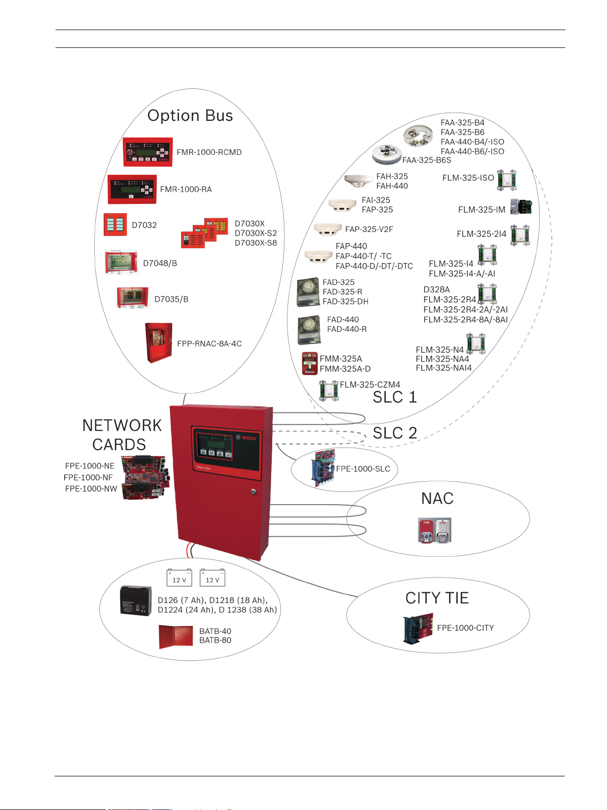
Analog Addressable Fire Panels Product Description | en 11
Figure 2.1 FPA-1000 System Architecture with Options
Optional Networking Cards allow multiple panels to be interconnected into a networked
system.
Bosch Security Systems, Inc. Installation and Operation Guide F.01U.173.607 | 01 | 2012.08

12 en | Product Description Analog Addressable Fire Panels
2.2 Features
System Configuration
– Basic configuration includes one analog addressable Signaling Line Circuit (SLC),
configurable as two Class B Style 4 or one Class A Style 6 or 7
– Second SLC easily expandable with FPE-1000-SLC Signaling Line Circuit
– Up to 254 detectors and modules, or up to 127 analog sounder bases in combination
with a suitable detector, for a total of 254 addressable device capacity per SLC
– SLC circuits use standard wire; no shielded or twisted pair required. Twisted pair wire,
CAT 5 cable, or fiber optic cable used on network connections.
– Programmable sensitivity levels per device, and automatic day and night sensitivity
modes
– Automatic calibration and drift compensation routine
– 120 V/240 V AC power, total 5.5 A transformer output
– Two integrated NAC circuits rated at 2.5 A each, allowing up to 4 A total current (shared
between AUX power, Option Bus, and NAC)
– Up to four addressable Remote Notification Appliance Circuit Power Supplies, providing
Aux power and up to 16 synchronized remote NAC circuits
– Mainboard NAC patterns include Steady, Pulsing, Temporal Code 3, and Temporal
Code 4, Wheelock, System Sensor, and Gentex
– Built-in synchronization for appliances from Wheelock, System Sensor, and Gentex
– Three programmable Form C relays on the mainboard (fire, trouble, supervisory, gas
alarm or activation by zone)
– Option Bus for optional boards and expansions including LCD/LED annunciators, Octal
Driver Module, Octal Relay Module, and Remote Notification Appliance Circuit Power
Supply
– Optional City Tie Plug-in Module FPE-1000-CITY with two circuits, each programmable to
Local Energy or Reverse Polarity
– Optional plug-in Networking Cards (three models) for connecting fire panels into a
networked system
– Built-in Ethernet interface for Conettix IP reporting and/or programming and diagnostics
– Built-in dual phone line PSTN/IP DACT communicator
– Contact ID, SIA 300 and Modem IIIa
– UL Listed, FM/CSFM/MEA approved
2
reporting formats
Ease of Use and Functionality
– Large 4-line by 20-character LCD display
– Six LED status indicators on each panel keypad or remote LCD annunciators, including
gas alarm LED
– Menu-driven user interface on panel
– Easy programming from panel keypad
– Browser-based user interface for programming and diagnostics running on a networked
PC with Microsoft Windows XP and Microsoft Windows Vista or Unix/Linux based
operating system, no software installation is required
– Programmable authority levels, secured with a user-definable four-digit PIN
– 225 software zones for flexible input-output mapping on a non-networked panel
– 128 local zones per panel and 97 grouped zones for flexible input-output mapping on a
network
– Programming option for sandwich alarm allows time-triggered phased evacuation
(evacuation floor by floor)
– Auto Learn feature for easy start-up programming
F.01U.173.607 | 01 | 2012.08 Installation and Operation Guide Bosch Security Systems, Inc.

Analog Addressable Fire Panels Product Description | en 13
– Local piezo sounder
– Fire drill test function
– Walk test function
– Alarm verification feature
– Bypass or unbypass point, output or zone individually
– 2999 events history buffer
– Event and history printing via network printer
– Three language versions (English, Spanish, and Portuguese), software configurable, LED
and keypad labeling easy exchangeable
– Programming option for IP reporting communication with the Advanced Encryption
Standard (AES)
Hardware Features
– Removable front door with keyed lock
– Removable dead front door to access electronics
– Mounting kit available for semi-flush installation with trim ring
– Metal oxide varistors (MOVs) and spark gaps for protection from lightning surges and
static discharges
Bosch Security Systems, Inc. Installation and Operation Guide F.01U.173.607 | 01 | 2012.08
14 en | Product Description Analog Addressable Fire Panels
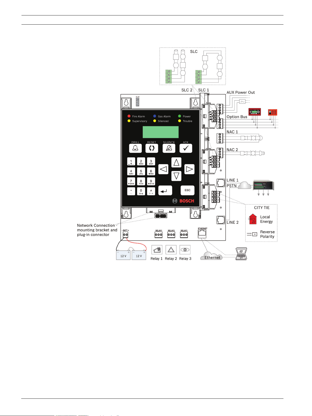
2.3 System Overview Mainboard Components
Figure 2.2 FPA-1000-UL Mainboard
F.01U.173.607 | 01 | 2012.08 Installation and Operation Guide Bosch Security Systems, Inc.

Analog Addressable Fire Panels Product Description | en 15
Designation Description
Keypad With LEDs, LCD display and keys.
Transformer Works with 120 V AC, 60 Hz or 240 V AC, 50 Hz.
SLC 1 / SLC 2 Signaling Line Circuit (SLC), standard configuration with one SLC,
second SLC with FPE-1000-SLC Plug-in Module,
nominal 39 V DC (30 to 40 V DC), 260 mA maximum (per SLC), powerlimited, supervised.
Option Bus Provides serial data interface, with 500 mA at 12 V DC, power-limited,
supervised.
AUX :
FWR- | FWR+
RST- | RST+
Two auxiliary power supply terminals, with 500 mA at 24 V DC each,
power-limited, non-supervised,
FWR = Full Wave Rectified, non-switched
RST = Resettable, switched and filtered.
NAC 1 / NAC 2 Terminal strips for two NACs, 2.5 A each.
Wiring options ClassA StyleZ or ClassB StyleY.
See wiring example Figure 2.2 on Page 14:
–NAC1: ClassA StyleZ
–NAC2: ClassB StyleY
CITY TIE Slot for City Tie Plug-in Module FPE-1000-CITY.
Networking Card Slot for one of three models of Networking Card.
RELAY 1
RELAY 2
RELAY 3
Mainboard relays, default assignment is for alarm, trouble and
supervisory; individually programmable for alarm, trouble, supervisory,
gas alarm, activation by zone and system events,
rated at 5 A, 30 V DC/10 A, 120 V AC.
LINE 1 / LINE 2 Phone line connections through central station receiver (2 x RJ45).
ETHERNET Ethernet connection (RJ45).
BATT Terminal strip for battery connection, 2 x 12 V, 18 Ah maximum within
enclosure or 40 Ah maximum external.
Tab le 2. 1 Mainboard (MB) Components
The boards, expanders and devices, listed in the following sections, are available from Bosch
Security Systems, Inc. to be used with the FPA-1000 fire panels. For a complete description of
and installation instructions for each product, refer to the appropriate section of this manual
and the documents supplied with the device.
2.4 Plug-in Modules
The following plug-in modules are available for the FPA-1000 fire panels:
Type Number Description
FPE-1000-NE Ethernet Networking Card
FPE-1000-NF Fiber Optic Networking Card
FPE-1000-NW Wired Networking Card
FPE-1000-SLC Signaling Line Circuit (second circuit or replacement)
FPE-1000-CITY City Tie Plug-in Module
Tab le 2. 2 Plug-in Modules
Bosch Security Systems, Inc. Installation and Operation Guide F.01U.173.607 | 01 | 2012.08

16 en | Product Description Analog Addressable Fire Panels
When a networked system of fire panels is desired, the Networking Cards provide the means
to interconnect the panels.
A second Signaling Line Circuit (SLC) can easily be added by plugging in the FPE-1000-SLC to
the mainboard.
The City Tie Plug-in Module FPE-1000-CITY provides two circuits which can be programmed as
Local Energy or Reverse Polarity mode
Compatible Gamewell Devices for the City Tie Plug-in Module in Local Energy Mode
Designation Description
M34-56 Local energy Trip, Surface Mount, Cottage Shell
M34-110 Same as M34-56 wth plain door painted blue
M34-111 Same as M34-56 wth plain door painted red
M34-112 Same as M34-56 wth plain door painted yellow
M34-92 Local energy Trip, Flush Mount, Gasketed cast frame for interior and
exterior use
M34-113 Same as M34-92 wth plain door painted blue
M34-114 Same as M34-92 wth plain door painted red
M34-75 Local energy Trip, Surface Mount, Cottage Shell (less inner case test
block, tap key & bell)
M34-115 Same as M34-75 wth plain door painted blue
M34-116 Same as M34-75 wth plain door painted red
M34-72 Local energy Trip, Sheet Metal Housing (less inner case test block, tap
key & bell), Plain Door
Tab le 2. 3 Compatible Gamewell Devices for the City Tie Plug-in Module in Local Energy Mode
2.5 Power Supply
A transformer working with 120 V AC or 240 V AC is supplied standard with the control panel.
Two backup batteries with 7 Ah or 18 Ah each fit inside the fire panel cabinet. A separate
battery box can provide higher capacity.
Each FPA-1000 provides two auxiliary power supplies: one 0.5 A at 24 V FWR; one 0.5 A
at 24 V DC RST (resettable). This auxiliary power can run expansion boards or other low
current auxiliary devices.
Table 2.4 lists the available batteries and battery boxes. For selecting the necessary battery
capacity, use the Microsoft Excel based FPA-1000_Battery_Calculator.xls. The spreadsheet is
available on the product CD or can be downloaded at www.boschsecurity.us.
F.01U.173.607 | 01 | 2012.08 Installation and Operation Guide Bosch Security Systems, Inc.

Analog Addressable Fire Panels Product Description | en 17
Type Number Description
D126 Battery 12 V, 7 Ah
D1218 Battery 12 V, 18 Ah
D1224 Battery 12 V, 24 Ah
D1238 Battery 12 V, 38 Ah
BATB-40 Battery Box
– Provides a single level (two-battery capacity) of battery storage
with an optional shelf that increases the battery capacity to four
batteries.
BATB-80 Battery Box
– Includes a mounted shelf that holds up to four batteries.
Tab le 2. 4 Available Batteries and Battery Boxes
For installations requiring battery capacity higher than 40 Ah, a regulated and UL 1481 Listed
external power supply can be used. The external power supplies connect through the panel's
battery terminals. Batteries and battery charger are not supervised. For supervision of AC and
battery fault use an input module (for example FLM-325-2I4) on the SLC.
2.6 Components Connected to the Option Bus
Remote Command Center and Annunciators
Each FPA-1000 supports
– up to a total of eight FMR-1000-RCMD Remote Command Centers and/or FMR-1000-RA
Remote Annunciators
– up to eight D7030X Series LED Annunciators with eight LED Zones each
– up to eight D7030X Series/D7032 combinations.
Bosch Security Systems, Inc. Installation and Operation Guide F.01U.173.607 | 01 | 2012.08

18 en | Product Description Analog Addressable Fire Panels
Type Number Description
FMR-1000-RCMD Remote Command Center
– Remote operational terminal of the FPA-1000 panel, providing
buttons for silence, reset, acknowledge, drill, scrolling keys, key
switch with 1358 key, built-in piezo sounder.
FMR-1000-RA Remote Annunciator
– Remote LCD annunciator, providing key for acknowledge and
scrolling keys, built-in piezo sounder.
D7030X LED Annunciator
– Identifies the location of a fire alarm for up to eight zones allowed
per system.
D7030X-S2 LED Annunciator
– With two zones reserved for supervisory functions.
– With power and trouble LEDs plus eight-zone LEDs that can be
individually labeled.
D7030X-S8 LED Annunciator
– With eight zones reserved for supervisory functions.
– With power and trouble LEDs plus eight-zone LEDs that can be
individually labeled.
D7032 Eight-Point LED Annunciator Expander
– Attaches to a D7030X, D7030X-S2 or D7030X-S8.
– Identifies the location of a fire alarm for eight additional zones,
showing 16 LED zones in the D7030X/D7032 combination.
Tab le 2. 5 Controls and Annunciators for Connection to the Option Bus
For requirements of Option Bus address restrictions, refer to Section 3.4.1 Option Bus Address
Assignment on Page 39.
For wiring requirements, refer to Section 4.9 Option Bus Wiring on Page 67.
Modules
Each FPA-1000 supports up to two Octal Relay Modules or Octal Driver Modules.
The outputs are fully programmable, and can be activated by system events. These outputs
have the same programming options as the local relays. Each output operates independently
of the other seven to provide complete flexibility. Communication with the D7035/B or
D7048/B is supervised.
Type Number Description
D7048/B Octal Driver Module
D7035/B Octal Relay Module
Tab le 2. 6 Modules for Connection to the Option Bus
For wiring requirements, refer to Section 4.9 Option Bus Wiring on Page 67.
For requirements of address restrictions, refer to Section 3.4.1 Option Bus Address Assignment
on Page 39.
NAC Power Supply
The FPP-RNAC-8A-4C Remote Notification Appliance Circuit Power Supply adds four
additional Notification Appliance Circuits (NFPA72, ClassA StyleZ or ClassB StyleY) to the
fire panel or serves as a power supply for fire protective signaling systems. This regulated
power supply provides up to 8 A of power that is used to recharge batteries and operate
F.01U.173.607 | 01 | 2012.08 Installation and Operation Guide Bosch Security Systems, Inc.

Analog Addressable Fire Panels Product Description | en 19
continuous and intermittent alarm loads. This 8 A of power can be distributed through the
four NAC Power Supply circuits that are part of the FPP-RNAC-8A-4C. The FPP-RNAC-8A-4C is
UL Listed for use in commercial fire alarm applications.
Type Number Description
FPP-RNAC-8A-4C Remote Notification Appliance Circuit Power Supply
Tab le 2. 7 NAC Power Supply Connected to the Option Bus
For wiring requirements, refer to Section 4.9 Option Bus Wiring on Page 67.
2.7 Signaling Line Circuit Devices
The FPA-1000 fire panels communicate with each of the analog addressable devices located
on the SLCs using fast and reliable protocol that allows the use of standard non-twisted, nonshielded wiring for the SLCs.
Each FPA-1000 supports two Class B, Style 4 or one Class A, Style 6 or 7 per SLC.
Table 2.8 lists all compatible devices for the FPA-1000 SLCs:
Bosch Security Systems, Inc. Installation and Operation Guide F.01U.173.607 | 01 | 2012.08

20 en | Product Description Analog Addressable Fire Panels
Type Number Description
FAP-440-T
FAP-440-TC
FAP-440-DT
FAP-440-DTC
[SMOKE-M]
FAP-325-V2F
[SMOKE-P]
FAP-325
FAP-440
FAP-440-D
[SMOKE-P]
Analog Multisensor Detector Photo/Heat
Analog Multicriteria Detector Photo/Heat/CO
– Incorporates a thermal element and a high performance
photoelectric smoke chamber. The -TC model includes a carbon
monoxide (CO) sensor as an indicator of fire.
– Provides two user-selectable modes for making the fire decision:
multi-combined and multi-separated mode.
– Allows programming LED behavior during polling of the internal
device LED and a remote connected indicator.
– D models incorporate dual photoelectric emitters (infrared and blue)
to enhance catch performance.
– Can use addresses 1 to 254.
Analog Photoelectric Smoke Detector Flat Head
– Detects optically dense smoke typical of fires involving materials
such as soft furnishings, plastic, foam or other similar materials
which tend to smolder and produce large visible smoke particles.
– Allows programming LED behavior during polling of the internal
device LED and a remote connected indicator.
– Can use addresses 1 to 254.
Analog Photoelectric Smoke Detector
Analog Photoelectric Detector
– Detects optically dense smoke typical of fires involving materials
such as soft furnishings, plastic, foam or other similar materials
which tend to smolder and produce large visible smoke particles.
– The D model incorporates dual photoelectric emitters (infrared and
blue) to enhance catch performance.
FAH-325
FAH-440
[HEAT]
Analog Heat Detector
Analog Heat Detector
– Detects heat in environments where smoke detectors are unsuitable
because of the presence of steam or cooking fumes, such as in a
kitchen.
FAI-325
[SMOKE-I]
Analog Ionization Smoke Detector
– For use in areas where early warning of trouble from superheated or
flaming combustibles is expected; also constructed to be used
effectively where outside Radio Frequency Interference (RFI) and
other electrical interference is expected.
FAA-325-B4
FAA-440-B4
FAA-440-B4-ISO
Analog Detector Base
Analog Standard Base (4-inch)
Analog Isolator Base (4-inch)
– Compatible with all analog addressable detectors that use the
advanced analog communication protocol, except the FAD-325-DH.
– 4-in (10 cm) diameter.
– ISO base contains built-in circuit isolator.
F.01U.173.607 | 01 | 2012.08 Installation and Operation Guide Bosch Security Systems, Inc.

Analog Addressable Fire Panels Product Description | en 21
Type Number Description
FAA-325-B6
FAA-440-B6
FAA-440-B6-ISO
FAD-325-DH
FAD-325-R
[SMOKE-D]
FMM-325A
FMM-325A-D
[CONT-MOD]
Analog Detector Base
Analog Standard Base (6-inch)
Analog Isolator Base (6-inch)
– Compatible with all analog addressable detectors that use the
advanced analog communication protocol, except the FAD-325-DH.
– 6-in (15 cm) diameter.
– ISO base contains built-in circuit isolator.
Analog Duct Smoke Sensor Replacement
Analog Duct Smoke Detector
– Provides early detection of smoke and products of combustion
present in air moving through HVAC ducts in Commercial, Industrial
and Residential applications.
The FAD-325-DH is a replacement for the sensor in either of the following
units:
– FAD-325 Analog Duct Smoke Detector (with Housing)
– FAD-325-R Analog Duct Smoke Detector with Relay (with Housing)
Single-action Analog Manual Station
Double-action Analog Manual Station
– Contact monitor module mounted in a corrosion-resistant rugged die-
cast housing for single-gang mounting.
– Loop powered.
The FMM-325A/FMM-325A-D devices are connected via an FLM-325-IM
Contact Module. For programming, refer to the Contact Monitor
information.
FLM-325-I
[CONT-MOD]
FLM-325-2I4
[CONT-MOD]
Contact Monitors
– Designed to use with pull stations, water-flow switches, and other
applications requiring the monitoring of dry-contact alarm-initiating
devices.
– Can be programmed in NO EOL, NC EOL, NC no EOL.
Two types available for input switches to be connected as Class B:
– FLM-325-I4 Contact Monitor 4-inch
– FLM-325-IM Contact Monitor, Mini
Independently from the type, the panel lists only an FLM-325-I.
Two types available for input switches to be connected as Class A:
– FLM-325-I4-AI Contact Monitor 4-inch Class A w/Isolator
– FLM-325-I4-A Contact Monitor 4-inch Class A
The types FLM-325-IM, FLM-325-I4-AI, and FLM-325-I4-A can use
addresses 1 to 254.
Dual Input Monitor
– Provides two independent contact monitoring circuits while utilizing
only one address on the SLC.
– Can be programmed to monitor normally open or normally closed
contact fire alarm and supervisory devices (NO EOL, NC EOL,
NC no EOL)
– Supervises with Style B (Class B), loop powered.
Bosch Security Systems, Inc. Installation and Operation Guide F.01U.173.607 | 01 | 2012.08

22 en | Product Description Analog Addressable Fire Panels
Type Number Description
FLM-325-CZM4
[CONVZ-MOD]
FLM-325-2R4
[RELAY-MOD]
Conventional Zone Module
– Monitors dry contacts (NO) devices such as two-wire conventional
detectors or pull stations.
– Transmits the status of one zone of devices back to the panel
(25 maximum per zone; number depends on type of connected
devices).
– Class A or Class B wiring is configured with a jumper on the module
– Auxiliary (AUX) powered.
For compatible devices, refer to the manual supplied with the product.
The number of Conventional Zone Modules (FLM-325-CZM4) for eachSLC
module is limited to 32.
Dual Relay Modules
– Allows independent control of two Form C contacts for a variety of
normally open (NO) and normally closed (NC) contact applications
such as fan operation, elevator recall, door closure, and auxiliary
notification.
– Loop powered.
Five types available:
– FLM-325-2R4 Dual Relay Module,
rated for 1.0A at 30VDC or 0.5A at 125VAC
– FLM-325-2R4-2A Dual Relay Module 2A,
rated for 2.0A at 30VDC or 1.0A at 125VAC
– FLM-325-2R4-2AI Dual Relay Module 2A w/Isolator
rated for 2.0A at 30VDC or 1.0A at 125VAC
– FLM-325-2R4-8A Dual Relay Module 8A,
rated for 8.0A at 30VDC or 8.0A at 250VAC)
– FLM-325-2R4-8AIDual Relay Module 8A w/Isolator,
rated for 8.0A at 30VDC or 8.0A at 250VAC)
The types FLM-325-2R4-2A, FLM-325-2R4-2AI, FLM-325-2R4-8A and
FLM-325-2R4-8AI can use addresses 1 to 254.
D328A
[RELAY-MOD]
Analog Relay Module
– Allows the control of one Form C contact (rated for 1.0 A at 30 V DC
or 0.5 A at 125 V DC) for a variety of normally open (NO) and
normally closed (NC) contact applications such as elevator recall
systems or HVAC shutdown.
– Loop powered.
F.01U.173.607 | 01 | 2012.08 Installation and Operation Guide Bosch Security Systems, Inc.

Analog Addressable Fire Panels Product Description | en 23
Type Number Description
FLM-325-N4
[NAC-MOD]
FLM-325-ISO Short Circuit Isolator
Tab le 2. 8 Compatible SLC Devices
When programming the SLC devices, first select the device group type and then specify the
type number.
Refer to the type designations in brackets in Table 2.8, or refer to Section SLC Configuration
beginning on Page 171.
Supervised Output Module
– Provides a supervised pole reversal output used for acoustic and
optical signaling devices or to trigger a Remote Notification Appliance
Circuit Power Supply.
– Requires a 24 V DC auxiliary input voltage.
– The output relay is rated to supply 2 A at 30 V DC.
– Provides Steady, Pulsing and Temporal Code 3 output pattern
Class B type:
– FLM-325-N4 Supervised Output Module
Two types available for Class A:
– FLM-325-NA4 Supervised Output Module Class A
– FLM-325-NAI4 Supervised Output Module Class A w/Isolator
The types FLM-325-NA4 and FLM-325-NAI4 can use addresses 1 to 254.
– Isolates a shorted section on a specific polling circuit from the rest of
the system to minimize the loss of devices.
2.8 Notification Appliance Circuit Devices
Two Class A Style Z or Class B Style Y Notification Appliance Circuits (NACs) provide up to 4 A
of 24 V power (maximum 2.5 A on each circuit) to operate horns, strobes, bells, and other
notification appliances. Each NAC can be programmed to provide Temporal Code 4, Temporal
Code 3, and Steady, Pulsing, and synchronized output for Wheelock, System Sensor, and
Gentex notification appliances.
Refer to the Compatibility List (P/N F.01U.075.636), available as a PDF at:
www. boschsecurity.us
Refer to Section 3.15 Programming Requirements According to UL 864 on Page 46 for UL
approved patterns.
2.9 Communicator
Each FPA-1000 has a dual phone line PSTN/DACT circuit and an Ethernet connection featuring
Conettix IP reporting. The panel communicates in Contact ID, SIA, and Modem IIIa2.
The panel provides miscellaneous reporting functions such as dialing control and transmission
supervision, priorities of report groups, routing to destinations, manual and auto test reports,
and Anti-Replay feature.
For the primary and secondary account, the following features are programmable:
– Two different phone or IP numbers
– Different dialing types for PSTN (pulse only, tone and pulse, or tone only)
– Individual PSTN line supervision (audible and visible trouble signal in the case of a
transmission path failure)
– Selectable options for Report Steering Groups
Bosch Security Systems, Inc. Installation and Operation Guide F.01U.173.607 | 01 | 2012.08

24 en | Product Description Analog Addressable Fire Panels
– Programmable acknowledge wait time for each Conettix IP reporting account (15 to
255 seconds)
– Test call frequency individually programmable for each account (4-, 12-, 24-hour, 7- and
28-day intervals; standard frequency 24 hours)
With modem function, it is possible to program the control panel remotely (upload a new
parameter file to the panel from a remote station).
Compatible Device for the PSTN/DACT Circuit and Ethernet Connection
Designation Description
D6600 Communications Receiver/Gateway
D6100i Communications Receiver/Gateway
Tab le 2. 9 Compatible Devices for the PSTN/DACT Circuit and Ethernet Connection
2.10 Components and Accessories
For semi-flush mounting of the control panel cabinet, the FPM-1000-SFMK Semi-flush
Mounting Kit with trim ring is available.
The D5070 Analog Device Pogrammer provides easy programming of Signaling Line Circuit
device addresses.
Alternatively to the complete FPA-1000 Analog Addressable Fire Panel, you can order separate
components; the FPA-1000-LC includes the mainbord with keypad, and the FPM-1000-ENC
includes the enclosure with the dead front door.
Type Number Description
FPM-1000-SFMK Semi-flush Mounting Kit
– Includes trim ring and mounting accessories.
D5070 Analog Device Programmer
– Hand held device that programs address settings on EEPROM-
– With base for detector head programming and two-module
– Shows the current analog value of a connected detector.
FPA-1000-LC Fire Panel Less Enclosure
FPM-1000-ENC Enclosure With Dead Front Door
Tab le 2. 10 Optional Accessories for the FPA-1000 Analog Addressable Fire Panels
2.11 Related Documents
To obtain a complete understanding of specific features of the fire control panel and related
peripherals, see the following documentation:
– NAC Compatibility List
– Operating Instruction Sheet, FPA-1000
– Wiring Diagram
– Release Notes
– Installation Guide FPE-1000-SLC Signaling Line Circuit
– Installation Guide FPE-1000-CITY City Tie Plug-in Module
– Installation Guide FPM-1000-SFMK Semi-flush Mounting Kit
– Installation and Operation Guide FMR-1000-RCMD Remote Command Center
programmable analog devices.
program adapter for module programming (for 4-in or single-gang
back box).
F.01U.173.607 | 01 | 2012.08 Installation and Operation Guide Bosch Security Systems, Inc.

Analog Addressable Fire Panels Product Description | en 25
– Installation and Operation Guide FMR-1000-RA Remote Annunciator
– Installation Guide FPM-1000-ENC Enclosure With Dead Front Door
If your system is networked, also see the following:
– Networking Cards Installation Guide
– Networking Quick Guide
All documents (in PDF format) and panel related software can be downloaded at:
www. boschsecurity.us
You might also find the current version of all documents supplied with the devices.
Bosch Security Systems, Inc. Installation and Operation Guide F.01U.173.607 | 01 | 2012.08
26 en | Planning Information Analog Addressable Fire Panels
3 Planning Information
NOTICE!
If the panel is to be used in a networked system, be careful to plan properly before installing
any panels. Check:
– whether the networked panels will be installed near each other or distributed over a
wider area
– whether or not any of the networked panels will be in different buildings
– the types and numbers of Networking Cards needed
– interconnection requirements, including the maximum allowable cable lengths which
depend on the intended interconnection method (Ethernet, fiber optic cable, or wire)
For each panel, be careful to plan properly before installing any devices. Check:
– the compatibility and number of devices to be connected
– the battery capacity needed
– the wiring requirements, including the maximum allowed cable length
– the installation requirements according to this Installation and Operation Guide,
NFPA 72, Local Codes and the Authority Having Jurisdiction (AHJ).
WARNING!
Any panel in a network can control all other panels in the network (e.g. silencing an alarm,
resetting the system, etc.). Access to panels should be restricted to properly trained
personnel.
3.1 Power Supply Calculations
To select the proper battery size for your system, calculate the required total current draw of
your system using the Microsoft Excel based FPA-1000_Battery_Calculator.xls. The spreadsheet
is available on the product CD or can be downloaded at www.boschsecurity.us.
3.2 Network Wiring/Connection Considerations
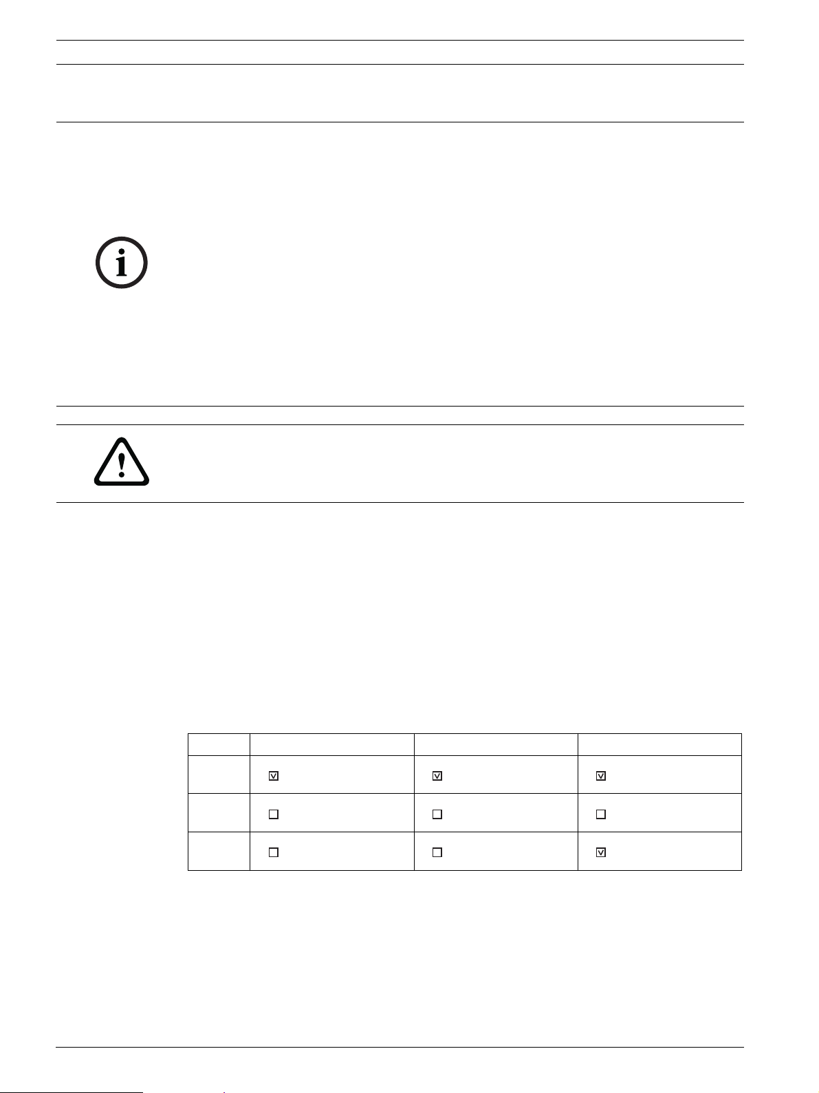
3.2.1 Ground Fault Detection
Each networking card has a specific terminal or terminals that are Ground Fault Detection
enabled. As indicated by the checked boxes in the following table, Port 1 on all three
networking cards is ground fault enabled; as is Port 3 on the wired card (FPE-1000-NW).
Port -NE -NF -NW
1 Ethernet IN Ethernet IN Wired IN
2 Ethernet OUT Fiber IN Wired OUT
3 Ethernet Fiber OUT Ethernet IN
Tab le 3. 1 Network Port Identification
For Ground Fault Detection to work properly, one and only one end of a communication
connection (cable) joining two networking cards must be Ground Fault Detection enabled. To
facilitate this, the wired card (FPE-1000-NW) and the fiber optics card (FPE-1000-NF) each
have a jumper located near the back of the the Ethernet IN port (Port 1 on the wired card and
Port 3 on the fiber optic card). This jumper allows Ground Fault Detection to be disabled for
this port. Recommended communication connection practice is to come out of one card and
in on the next. In cases where you are switching from a wired or fber optic card to a different
F.01U.173.607 | 01 | 2012.08 Installation and Operation Guide Bosch Security Systems, Inc.

Analog Addressable Fire Panels Planning Information | en 27
type of card, you must use the Ethernet port which should be OUT not IN which is the default.
Move the jumper on this card so that Ground Fault Detection is disabled at this end of the
connection (making it an Ethernet OUT). Remove the jumper from both pins and replace it on
only one pin so that it does not get misplaced in case Ground Fault Detection needs to be reenabled later.
3.3 Configuration and Programming Basics
3.3.1 Points
A point is defined as a device such as an automatic detector, a call point, or input line. Each
point in the system is individually identified by the control unit and can be programmed with
specific functions or responses.
Possible states are:
–Normal
–Active
–Bypassed
–Trouble
–Walk test mode
A point can have only one state at a time.
The point is activated in either of the following cases:
– The analog value of an analog detector crosses its threshold level.
– An input monitor is activated.
The point is dirty if the clean air value reaches a defined upper limit (depending on detector
type). This takes place automatically during the calibration processes. After the panel is
initialized successfully, the test interval for the calibrated detector sensitivity testing is
4 hours. The dirty condition is handled as a trouble status. If the clean air value is out of
range, a calibration trouble status is indicated. The detector is still working, but the sensitivity
set point can be different from the configured value. This means the risk of a false alarm
increases.
The point is in trouble status in any of the following cases:
– Double address fault is detected on an address.
– Wrong type code error is detected.
– Missing device is detected on an address.
– Other types of fault conditions are detected.
If a point is in bypassed status, other status changes are ignored until it is unbypassed.
If a point is placed in walk test mode, activation and deactivation of this point are handled
differently. Any other condition changes are ignored until the point is no longer in walk test
mode.
The point is considered to be normal if it is not in any of the above states.
Point Types
Point type defines the condition that is indicated by activation of a point. Each point is
programmed with a type. Not all point types are possible on a certain point, especially on an
SLC point where a detector exists. Refer to Table 3.2 on Page 28 for details on device type
mapping and possible point types for each SLC device type. The panel lists only the
acceptable point types for that SLC device.
Each of the points in the system can be programmed with its own characteristics. Point types
simplify the programming of points by allowing you to define a common set of characteristics
for similar points, and then assigning those characteristics to selected points as a point type.
Each point is assigned to use the characteristics of one point type, and then is individually
programmed for additional characteristics.
Bosch Security Systems, Inc. Installation and Operation Guide F.01U.173.607 | 01 | 2012.08

28 en | Planning Information Analog Addressable Fire Panels
SLC Device Group Type
FPA-1000
Point Type
SMOKE-M SMOKE-P, SMOKE-I,
SMOKE-D, HEAT
CONVZ-MOD CONT-MOD
Fire Automatic D D D P
Fire Alarm Manual P D
Waterflow PP
Waterflow Delay P P
Gas Alarm PP
Supervisory P P P P
Generic PP
Trouble PP
AC Failure PP
Battery Failure P P
Reset PP
Silence PP
Drill PP
Acknowledge P P
General Fire Alarm P
D = default point type P = possible point
type
[Blank] = not
available
SMOKE-M = FAP-440-T, FAP-440-TC, FAP-440-DT, FAP-440-DTC
SMOKE-P = FAP-325, FAP-325-V2F, FAP-440, FAP-440-D
SMOKE-I = FAI-325
SMOKE-D = FAD-325, FAD-325-R, FAD-325-DH
HEAT = FAH-325, FAH-440
CONVZ-MOD = FLM-325-CZM4
CONT-MOD = FLM-325-2I4, FLM-325-I4, FLM-325-IM, FLM-325-I4-A, FLM-325-I4-AI,
FMM-325A and FMM-325A-D Pull Stations connected via FLM-325-IM Contact Monitor are assigned to Fire Alarm
Manual by default and are programmable as Supervisory.
Table 3.2 Mapping Point Types to SLC Device Types
Generic point type can be used for output control with input activation. Activation of an input
programmed as Generic point type generates an entry "Generic" in history but no off-normal
event.
The point type General Alarm can be used for a key switch connected to a Contact Monitor
Module or Input Module (type CONT-MOD) to activate a fire alarm without delay. A General
Alarm overrides any Sandwich alarm delays (refer to Section 3.3.5 Special Alarm Features on
Page 37).
3.3.2 Advanced Point Features and Processing
The panel provides flexible handling on a point so that more optional features are
accomplished. These features are applicable to specific types. The control panel lists only
possible point features for that point type when programming on menu and Web pages.
Refer to Table 3.3 on Page 29 for mapping of point type to available point features:
F.01U.173.607 | 01 | 2012.08 Installation and Operation Guide Bosch Security Systems, Inc.

Analog Addressable Fire Panels Planning Information | en 29
Point Type Point Feature
Latching AV PAS/
Fire Automatic X
Pre-signal
1)
P
P
PAS (D)/
AV (N)
1)
P
Waterflow
Delay
AC Fail
Delay
Fire Alarm Manual X
Waterflow X
Waterflow delay X X
Gas Alarm X
Supervisory G
Generic
AC Failure X
General Fire Alarm X
AV = Alarm Verification
PAS = Positive Alarm Sequence
D = Day, N = Night
1)
Not for FAH-325
X = Fixed point feature
P = Programmable point feature
G = Dependent on global setting
Blank = not available
Tab le 3. 3 Mapping Point Types to Point Features
The following principles apply:
– For Supervisory point type, programming of latching or non-latching is panelwide.
– The point types Generic, Trouble, AC Failure, Battery Failure, Reset, Silence, Drill, and
Acknowledge are non-latching. Refer to Table 3.2 on Page 28.
– For Fire Automatic point type, only one of three programmable features can be selected:
AV, or PAS/Pre-signal or PAS (Day)/AV (Night). AV and PAS (Day)/AV (Night) do not apply
for the FAH-325 Analog Heat Detector.
Delay options can be selected individually for each SLC Fire Automatic input.
For programming details, see Section Edit a Device 6-PROGRAMMING, 1-SLC DEVICES, 1-
SLC 1, 2-EDIT A DEVICE or 6-PROGRAMMING, 1-SLC DEVICES, 2-SLC 2, 2-EDIT A DEVICE
on Page 112 and/or Section 6.7.2 SLC 1 and SLC 2 on Page 149).
The following table shows the prioritization of both delay settings:
Programming SLC Fire
Automatic Input
No delay No delay No delay No delay
AV AV AV AV
PAS/Pre-signal No delay PAS Pre-signal
PAS (D)/AV (N) AV PAS Pre-signal
AV = Alarm Verification
PAS = Positive Alarm Sequence
D = Day, N = Night
Day Mode (Site Data)
No delay PAS Pre-signal
Tab le 3. 4 Prioritization of Day Mode and SLC Input Delay Options
Alarm Verification
If an input point is configured as “Alarm verification enabled” and goes into an active state,
the panel does not immediately indicate the alarm and activate associated outputs, but resets
the input point and waits for a verification period (programmable) to see if the point is still
active.
Bosch Security Systems, Inc. Installation and Operation Guide F.01U.173.607 | 01 | 2012.08
30 en | Planning Information Analog Addressable Fire Panels
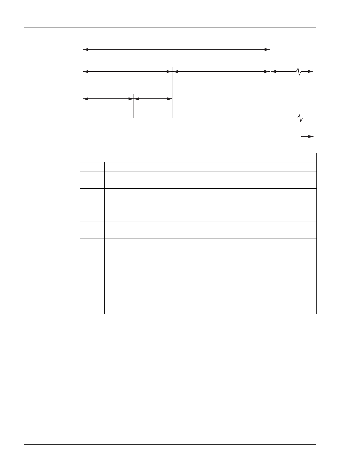
ALARM VERIFICATION PERIOD (programmable 60 to 180 seconds)
RETARD-RESET-RESTART PERIOD
No Alarm At Control Unit
(not configurable, 30 seconds max.)
RETARD-RESET PERIOD
Control Unit
(20 seconds)
CONFIRMATION PERIOD
Alarm Required At Control Unit
POWER-UP PERIOD
Detector Restart
OPTIONAL
REGION
AB DEC
0 seconds
Figure 3.1 Alarm Verification Timing Diagram
time
Legend
A Smoke detector goes into alarm.
A→B RETARD-RESET PERIOD: Control unit senses detector in alarm and retards
(delays) alarm signal. Fixed, 20 seconds.
B→C POWER UP PERIOD: Power to the detector is reapplied and time is allowed for
detector to become operational for alarm (detector restart). Time depends on the
device type (detector maximum 3 seconds, Conventional Zone Module maximum
10 seconds).
A→C RETARD-RESET-RESTART PERIOD: No alarm obtained from control unit. Not
configurable, 30 seconds maximum.
C→D CONFIRMATION PERIOD: Detector is operational for alarm at point C. If detector is
still in alarm at point C, control unit will alarm. If detector is not in alarm, system
returns to standby. If the detector re-alarms at any time during the confirmation
period the control unit will alarm. Time depends on detector restart and overall
alarm verification period.
A→D ALARM VERIFICATION PERIOD: Consists of the retard-reset-restart and
confirmation periods. Programmable 60 to 180 seconds.
D→E OPTIONAL REGION: Either an alarm can occur at control unit or restart of the
alarm verification cycle can occur.
– Alarm verification is applicable only to analog smoke or 2-wire smoke detectors of the
Fire Automatic type. The alarm verification option is not applicable to Fire Alarm Manual
and Waterflow point types.
– The alarm verification option is arranged on a per point basis.
– After the alarm verification period starts, any alarm from anywhere in the system that
occurs during the alarm confirmation cycle immediately results in an alarm indication.
– The alarm verification timer is system wide; thus, only one timer applies for the whole
system.
– The alarm verification timer is user programmable, ranging from 90 to 180 seconds. The
default is 90 seconds. Refer to Section 3.15 Programming Requirements According to
UL 864 on Page 46.
– A reset command is sent to reset the input point on SLCs for alarm verification.
– The global alarm verification zone is activated if the panel is in the verification period.
– The Alarm Verification feature is valid in a networked system.
F.01U.173.607 | 01 | 2012.08 Installation and Operation Guide Bosch Security Systems, Inc.
 Loading...