

Fire Alarm Systems - FPE-8000-FMR Remote keypad
A B C
D
E
G F
FPE-8000-FMR Remote keypad
AVENAR keypad 8000
u User interface identical to fire panel
u High resolution display with bright colors to
indicate alarms and events
u 8" touch pad with fixed and programmable
buttons, thus adaptable to the situation
u Clean design for surface and flush mounting
u Alternative use as redundant panel controller
The remote keypad allows decentralized operation of
a fire safety system. The design of the graphical user
interface is identical to the fire panels. A color display
shows all messages. The touch screen is for operation
of a specific panel or the entire system. The userfriendly interface adapts to various situations. This
causes correct operation that is simple and clear as
well as targeted and intuitive.
Panels and keypads of the AVENAR series and the
FPA-5000 series(MPC-xxxx-B and MPC-xxxx-C) can be
combined in one panel network using the Ethernet
and the CAN bus interfaces.
In combination with an AVENAR panel 8000, the
keypad can be used as a redundant panel controller.
In this case, it cannot be used as a remote keypad.
Power can be supplied by the panel and/or an
external power supply unit.
The housing of the remote keypad is designed for
proper and clean installation at highly visible
locations. It allows tilted installation and surface or
flush wall mounting without requiring additional
installation frames.
The remote keypad is configured on a laptop using the
FSP-5000-RPS programming software. The
programming software enables further adaptation,
e.g. to country-specific requirements and regulations.
System overview
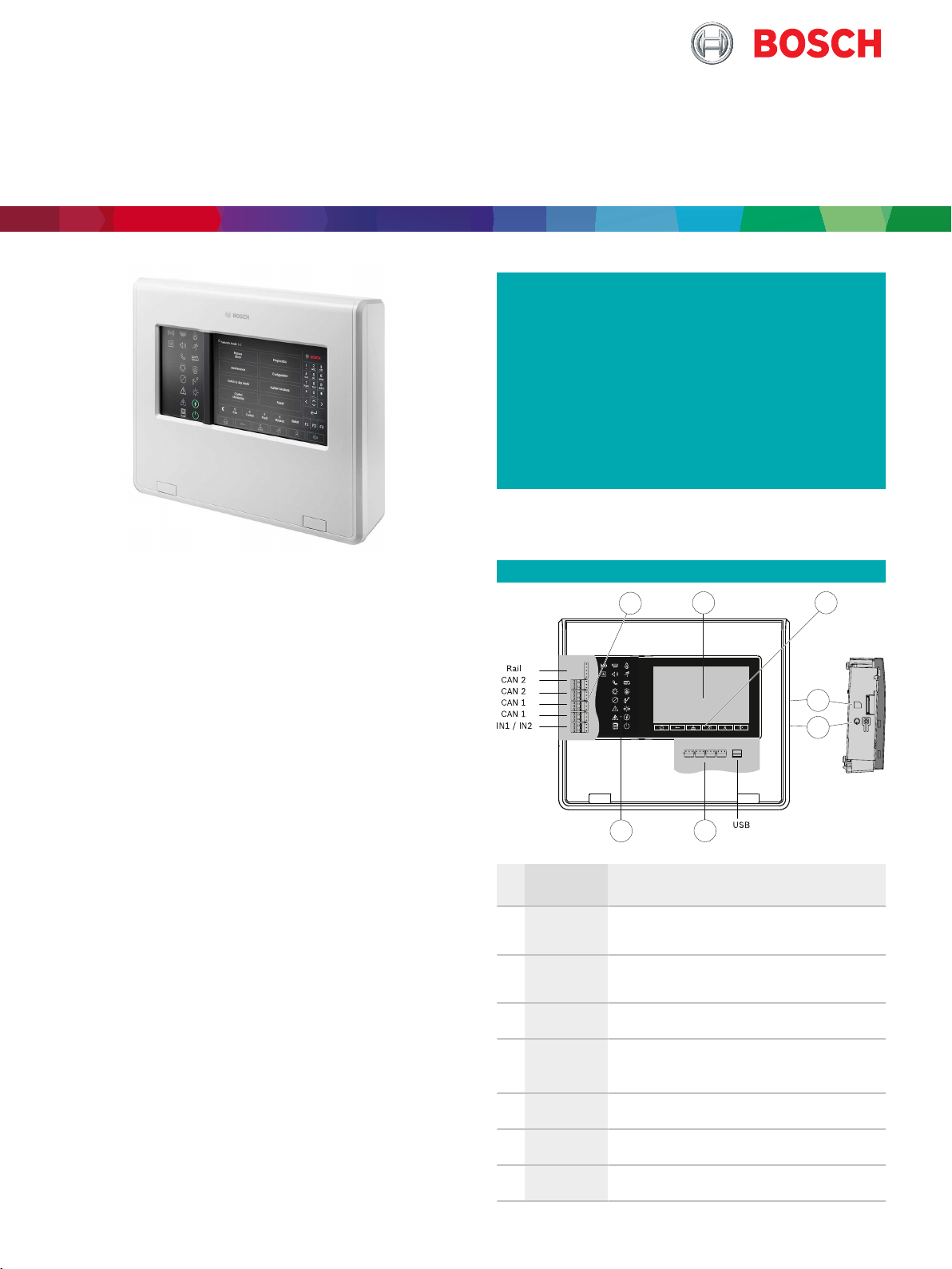
Pos.Designation Function
A
Interfaces
B
Touchscreen
C
6 fixed buttons
D
Memory card
slot
Power supply input, panel networking and inputs for
internal device monitoring
Operating the networked system through virtual
buttons and variable display windows
Standard entries
Memory card reader for maintenance services
E
Power button
Shutdown and restart of the device
F
Ethernet ports
G
18 LEDs
Panel networking and interface to various systems
Indicating the operating status
Fire Alarm Systems - FPE-8000-FMR Remote keypad
Ethernet
CAN
CAN
CAN
2 | 4
Functions
Alarm indication
All messages are shown on the display with a bright
color. The displayed messages contain the following
information:
• Message type
• Type of the triggering element
• Description of the exact location of the triggering
element
• Logical zone and sub-address of the triggering
element
18Icon LEDs give continuous information about the
operating status of the panel or the system. A red icon
LED shows an alarm. A blinking yellow icon LED
shows a fault. A steady yellow icon LED shows a
disabled function. A green icon LED shows proper
operation.
Two status LEDs, one red and one yellow, are
programmable. The red one shows a self-defined
alarm. The yellow one shows a self-defined fault or
deactivation.
Additional annunciator modules, each with 16red and
16yellow LEDs are available to indicate a larger
number of self-defined alarms, faults or deactivations.
Operation and processing of messages
For operating the panel, an 8 inch touch pad as input
medium is put upon the display. There are 6 buttons
with fixed functionality as well as 3 programmable
function keys.
Examples for the assignment of the function keys:
• Set the panel controller to day mode, set the panel
controller to night mode
• Enable detection points or outputs, disable
detection points or outputs
• Set standard sensor sensitivity, set alternative
sensor sensitivity
Each function key has a virtual status indicator.
At any time, an operator with sufficient user rights can
control the function keys.
Overview of evacuation zones and outputs
At any time, the operator can get a clear overview of
each evacuation zone and of each output connected
to the fire protection equipment. Each zone and each
output is marked with a programmable text label and
a clearly distinctive color reflecting the state: Green
shows idle state, power is available. Red shows an
activation during fire alarm condition, and fuchsia an
activation without a fire alarm condition. Yellow shows
a fault or disabled state. An operator with sufficient
user rights is able to start the evacuation in selected
zones and activate outputs connected to the fire
protection equipment through the user interface.
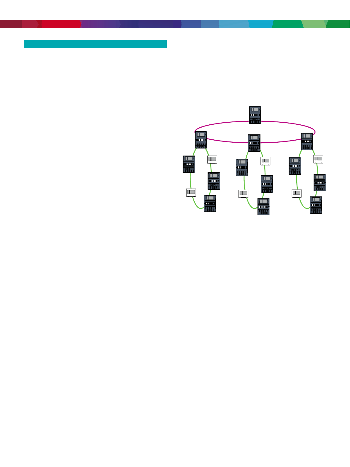
Networking
Up to 32panel controllers, remote keypads and OPC
servers can be combined to form a network.
Panels and keypads display all messages, or you can
form a group of panels and keypads. Within one
group, only messages of this group are displayed.
A variety of fire alarm network topologies are possible:
• CAN loop
• Ethernet loop
• Ethernet/CAN double loop
• CAN loop with Ethernet segments
• Ethernet backbone with sub-loops (Ethernet/CAN)
Languages
Languages
The operator can change the language of the user
interface. A printed quick user guide for each language
is supplied with the package. Following languages are
included: English, German, Bulgarian, Croatian, Czech,
Danish, Dutch, Estonian, French, Greek, Hungarian,
Italian, Latvian, Lithuanian, Polish, Portuguese,
Romanian, Russian, Serbian, Slovak, Slovenian,
Spanish, Swedish and Turkish.
Operator management
The system can have up to 200 different registered
operators. Login is permitted with a user ID and an 8digit pin code.
There are four different authorization levels.
Depending on the authorization level it is possible for
the operator to do certain functions according to
EN54-2.
Power supply
Power can be supplied by a fire panel and/or an
external power supply unit FPP-5000 (F.01U.511.307).
For applications requiring functional integrity, a
redundant power supply input is available. When the
primary power supply fails, the redundant power
supply can take over.
Use as redundant panel controller
In combination with an AVENAR panel 8000, standard
or premium license, an AVENAR keypad 8000 can be
used as a redundant panel controller. Only in this case
the rail connector is needed.

Fire Alarm Systems - FPE-8000-FMR Remote keypad
3 | 4
In case it is used as redundant panel controller, the
keypad has to be installed adjacent to the panel. Use
cable FPE-8000-CRK (F.01U.349.392) for connection
to panel rail. In normal operation, the user interface is
switched off until the main controller fails.
Interfaces
The Remote keypad features
• 2 CAN interfaces (CAN1/CAN2) for networking
• 1 Rail connector (for redundancy only)
• 4 Ethernet interfaces (1 / 2 / 3 / 4) for networking,
prescribed usage:
– 1 and 2 (blue): Panel network
– 3 (green): Building management system, hier-
archy panel
– 4 (red): Remote Services
• 2 signal inputs (IN1/IN2)
• 1 USB host interface for configuration via FSP-5000RPS
• 1 Memory card interface
• 2 Power supply connectors (DC1/DC2)
Certifications and approvals
Region Regulatory compliance/quality marks
Germany
Europe
VdS
CE
G 220049 AVENAR keypad 8000
AVENAR panel 8000 | AVENAR keypad
8000
Technical specifications
Electrical
Minimum operating voltage (VDC)
Maximum operating voltage (VDC)
Current consumption (mA at
20VDC)
Maximum power loss (W)
Max. CAN cable length in networks
Max. line resistance, DC1 (Ω)
Max. line resistance, DC2 (Ω)
Mechanical
Housing material
Color
Weight (kg)
Dimensions H x W x D (mm)
13.2
30
• standby: 200
• alarm: 480
12
Lmax = 1000 m, depending on
configuration, cable type and
topology
6
6
Polycarbonate (PC)
RAL9003, signal white (painted)
2.8
280.1x339x80.2
Installation/configuration notes
• As stipulated by EN 54-2, panels with more than
512 detectors and manual call points must be
equipped with a redundant panel controller.
Combined with an AVENAR panel 8000, an AVENAR
keypad 8000 can be used as a redundant panel
controller.
• The FSP-5000-RPS programming software enables
adaption to project- and country-specific
requirements. The programming software and the
associated documentation can be found at
www.boschsecurity.com for those with access
rights. Information about the programming software
is also included in FSP-5000-RPS online help.
Parts included
Quantity Component
1
1
4
FPE-8000-FMR Remote keypad
Product label
Screw, dowel
Flammability rating
LCD display (pixels)
Operating and display elements
Interfaces
Signal inputs
Power supply
Environmental
Protection class as per EN 60529
Permissible operating temperature
(°C)
Relative humidity at 25°C (%)
UL94-V0
7" color WVGA 800 x 480
• 6 keys
• 18 LEDs
CAN1, CAN2, ETH1, ETH2, ETH3,
ETH4, USB, Rail
IN1, IN2
DC1, DC2
IP 30
-5to+50
≤95 (non-condensing)

Fire Alarm Systems - FPE-8000-FMR Remote keypad
Ordering information
FPE-8000-FMR Remote keypad
Remote operating panel for performing the same
operating procedures as the control panel, enabling
variable operation of a networked system.
In combination with an AVENAR panel 8000, standard or
premium license, an AVENAR keypad 8000 can be used
as a redundant panel controller. Only in this case the rail
connector is needed.
Order number FPE-8000-FMR | F.01U.327.092
Accessories
FPE-8000-CRK Cable redundant keypad
Used to redundantly connect one remote keypad to a
panel controller.
Order number FPE-8000-CRK | F.01U.349.392
4 | 4
Represented by:
Europe, Middle East, Africa: Germany: North America: Asia-Pacific:
Bosch Security Systems B.V.
P.O. Box 80002
5600 JB Eindhoven, The Netherlands
Phone: + 31 40 2577 284
emea.securitysystems@bosch.com
emea.boschsecurity.com
Data subject to change without notice | 29485569803 | V12 | December 14, 2020 © Bosch Security Systems 2020
Bosch Sicherheitssysteme GmbH
Robert-Bosch-Ring 5
85630 Grasbrunn
Germany
www.boschsecurity.com
Bosch Security Systems, LLC
130 Perinton Parkway
Fairport, New York, 14450, USA
Phone: +1 800 289 0096
Fax: +1 585 223 9180
onlinehelp@us.bosch.com
www.boschsecurity.us
Robert Bosch (SEA) Pte Ltd, Security Systems
11 Bishan Street 21
Singapore 573943
Phone: +65 6571 2808
Fax: +65 6571 2699
apr.securitysystems@bosch.com
www.boschsecurity.asia
 Loading...