

Page 1
FPC-7034
EN
Installation Guide
Four Loop Expander
Page 2
FPC-7034 | Installation Guide | 1.0 Notice
1.0 Notice
These instructions cover the installation of the Bosch
Security Systems, Inc. FPC-7034 Four Loop Expander
in a fire system supervised by a Bosch FPD-7024 Fire
Alarm Control Panel (FACP).
Install, test and maintain the FPC-7034 according to
these instructions, NFPA 72, Local Codes and the
Authority Having Jurisdiction. Failure to follow these
instructions may result in failure of the detector to
operate properly. Bosch is not responsible for
improperly installed, tested or maintained devices.
These instructions contain procedures to
follow in order to avoid personal injury and
damage to equipment.
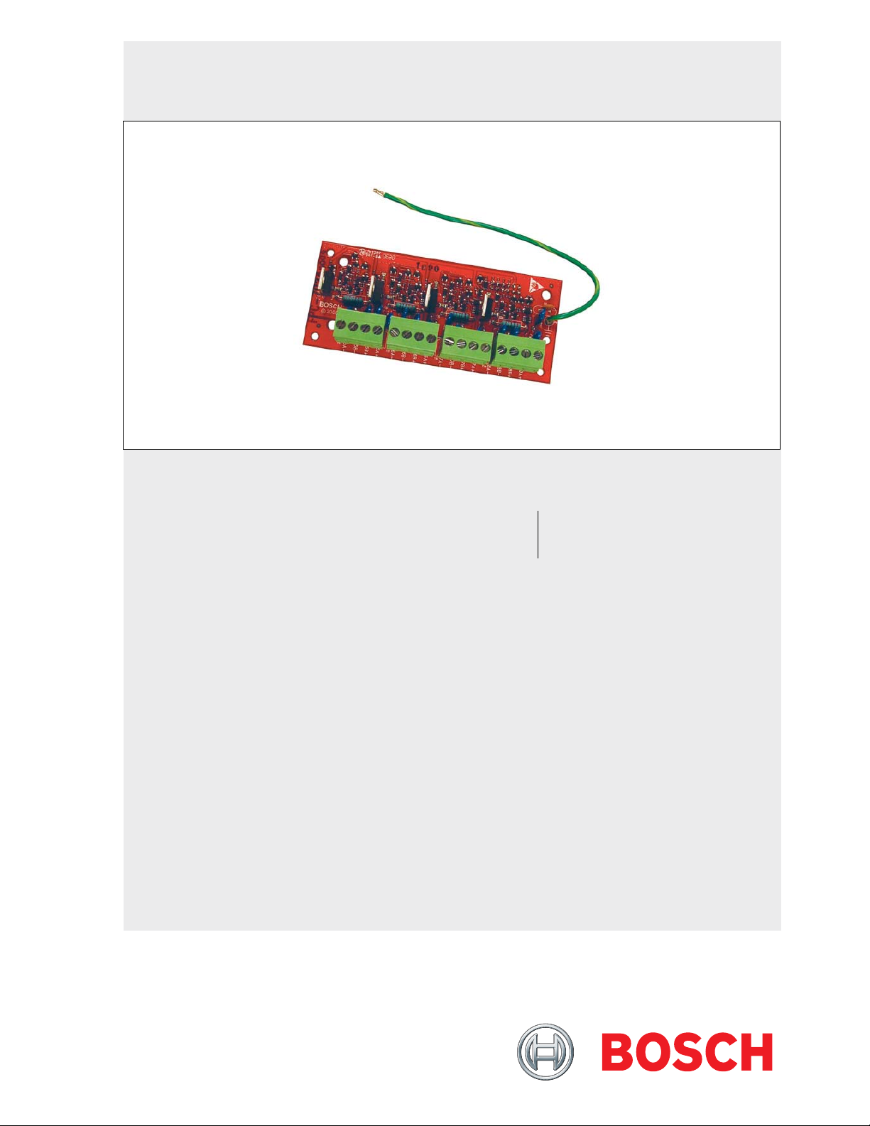
2.0 Device Description
The FPC-7034 allows an FPD-7024 FACP to support
four additional loops. The expander plugs into the
control and provides four Class B, Style B or Class A,
Style D loops that are identical in characteristics to the
loops on the control panel.
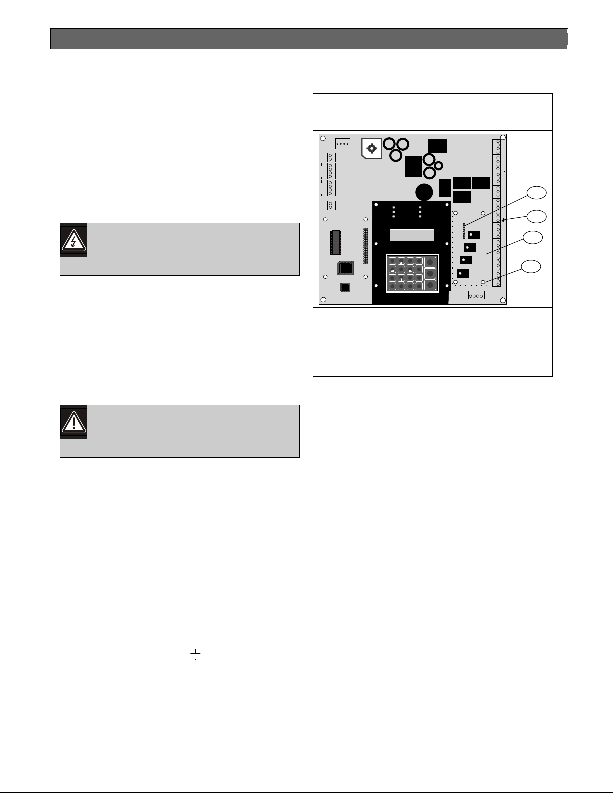
Refer to Figure 1 below and Figure 2 on page 3 for
installation details.
Figure 1: Installing the FPC-7034 on the
FPD-7024 Control Board
R2
HR2
HT2
AUXAUX+
A+
N
A
B+
C
B-
1
A-
A+
N
A
B+
C
B-
2
A-
BAT24V
BAT+
4 5 6
7 8 9
Back
*
Trouble
Power
Silenced
Alarm
Supervisory Gnd Flt
21 3
Drill
Acknowledge
Disable
Silence
Test
Reset
#
0
History
Prog
Enter
R B G Y OPTION BUS
T2
R1
RH1
TH1
T1
NC 3
COM3
NO 3
NC 2
COM2
NO2
NC 1
COM1
NO 1
SMK+
SMK-
4A+
4B+
4B4A-
3A+
3B+
3B3A-
2A+
2B+
2B2A-
1A+
1B+
1B1A-
1 - 8-Pin Connector
2 Connect Green/Yellow wire from FPC-7034
here
3 Location of FPC-7034
4 Holes for stand-offs
1
2
3
4
3.0 Installing the FPC-7034
Before installing the FPC-7034, remove
system power (AC and battery).
The FPC-7034 mounts on the FPD-7024 control board,
just to the right of the keypad. Use the four nylon
stand-offs supplied with the expander.
Use the following steps when connecting the FPC-7034
to an FPD-7024 control panel.
1. Install the four stand-offs into the four mounting
holes on the control.
2. Align the connector on the bottom of the
FPC-7034 with the eight pins extending from the
control board. Carefully press the FPC-7034 into
place.
3. Press each corner of the FPC-7034 until it is
locked onto each nylon stand-off.
4. Connect the green/yellow wire of the FPC-7034
to the ground terminal (
5. When power is restored, the FPC-7034 is
detected automatically and used by the system.
) on the control board.
2 Bosch Security Systems, Inc. | 9/08 | F01U005542-01
Page 3

FPC-7034 | Installation Guide | 4.0 Wiring
.
4.0 Wiring
The four loop inputs are wired the same as loop inputs
on the control board. Four EOL resistors are provided
with the FPC-7034 for installation at the end of each
point wiring run.
Figure 2: FPC-7034 Circuit Board
2
1
FRONT SIDEBACK SIDE
5.0 FPC-7034 Specifications
Table 1: FPD-7034 Power Requirements
Per Initiation Circuit
Alarm Current Threshold > 25 mA
Trouble Current Threshold < 7 mA
Normal Current > 7 mA and < 25 mA
Total Detector Standby Loop
Current
Alarm Current (Short Circuit) 46 mA
Supply Voltage 18.0 VDC to 25.5 VDC
Per Module:
Standby Current 60 mA
Alarm Current 184 mA
For additional specifications and device compatibility,
refer to the FPD-7024 Operation and Installation Guide
(P/N: F01U008458).
3 mA
1 - Earth ground wire (green with yellow stripe)
2 - 8-pin connector
Bosch Security Systems, Inc. | 9/08 | F01U005542-01 3
Page 4

Bosch Security Systems, Inc.
130 Perinton Parkway
Fairport, NY 14450-9199 USA
(800) 289-0096
© 2008 Bosch Security Systems
F01U005542-01
 Loading...