

Bosch FCS-320-TM, FCS-320-TM-R Operation Manual
FCS-320-TM Aspirating Smoke Detector
FCS-320-TM | FCS-320-TM-R
en Operation Guide


FCS-320-TM Aspirating Smoke Detector Table of Contents | en 3
Bosch Sicherheitssysteme GmbH Operation Guide F.01U.130.928 | 1.0 | 2009.11
Table of Contents
1 General 6
1.1 Introduction 6
1.2 Safety Instructions 6
1.3 Warranty 6
1.4 Copyright 7
1.5 Disposal 7
2 Technical Specifications 8
2.1 Product Description 8
2.2 Areas of Application 9
2.3 System Overview 12
2.4 Functions 13
2.5 FCS-320-TM Series Aspirating Smoke Detectors and Accessories 17
2.5.1 Overview 17
2.5.2 FCS-320-TM series connections 18
2.5.3 FCS-320-TM displays 19
2.5.4 FCS-320-TM-R displays 19
2.5.5 FAS-ASD-DIAG Diagnostic Software 20
2.5.6 External Detector Alarm Displays 20
2.6 Pipe system components 21
2.6.1 Overview 21
2.6.2 Air sampling openings 22
2.6.3 Ceiling Lead-through Adapter 23
2.6.4 Air-Return Pipe for Pressure Areas and Atmospheric Loads 24
2.6.5 Water Separator for Humid Areas 24
2.7 Scope of Delivery: Smoke Aspiration System 26
2.8 Technical data 28
2.8.1 FCS-320-TM series aspirating smoke detector 28
2.8.2 Pipe System 29
2.8.3 Smoke Aspiration System Components 29
3 Planning 31
3.1 Regulations 31
3.2 Principles of Pipe Planning 32
3.3 Airflow monitoring 34
3.4 Defining the Response Sensitivity 35
3.5 Planning Limits 36
3.6 Standard Pipe Planning 37
3.6.1 Determining the Necessary Accessories 37
3.6.2 Pipe Planning with Pipe Accessories 37
3.6.3 Planning with Air Filter 39
3.6.4 Opening Diameter 40
3.7 Planning with Single-hole Monitoring 42
3.7.1 I-pipe system 42
3.7.2 U-pipe system 43
3.7.3 M-pipe system 45

4 en | Table of Contents FCS-320-TM Aspirating Smoke Detector
F.01U.130.928 | 1.0 | 2009.11 Operation Guide Bosch Sicherheitssysteme GmbH
3.7.4 Double U-pipe system 46
3.8 Simplified Pipe Planning 47
3.8.1 I-Pipe System - Simplified Planning 47
3.8.2 U-Pipe System - Simplified Planning 48
3.8.3 M-pipe system - simplified planning 48
3.8.4 Double U-Pipe System - Simplified Planning 49
3.9 Planning for Forced Airflow 50
3.10 Power Supply 53
4 Installing the Aspirating Smoke Detector 55
4.1 General 55
4.2 Installing the Unit 55
4.3 Connection to the Fire Panel 59
4.3.1 Electrical Connection 59
4.4 Installation and electrical connection of auxiliary modules 60
4.4.1 Installing the reset board 60
4.4.2 Connection to fire panel with reset board 61
4.4.3 Installation of the relay board 61
4.4.4 Connecting the relay board 62
4.5 Settings via the FAS-ASD-DIAG Diagnostic Software 62
4.5.1 Setting the Response Sensitivity 62
4.5.2 Delay Time of the Alarm Triggering 63
4.5.3 Activation threshold of the airflow monitoring 63
4.5.4 Delay time for an airflow malfunction 63
4.5.5 Fault Indication 63
4.5.6 Dynamic airflow 63
4.5.7 ROOM·IDENT 63
4.5.8 LOGIC·SENS 64
4.5.9 Setting the Fan Voltage 64
4.5.10 Entering the current air pressure 64
4.5.11 Entering the height above sea level 64
4.6 Data Logging 64
5 Installation of the Pipe System 66
5.1 Length Change of the Pipe System 67
5.2 Air sampling openings 68
5.3 Ceiling Lead-through Adapter 70
5.4 Monitoring with Forced Airflow 71
5.4.1 Detection at Intake and Exhaust Openings 71
5.4.2 Detection in the Bypass 71
5.5 Air filter 72
5.5.1 Installing the Air Filter Box 72
5.6 Air-return Pipe 72
5.7 Three-way tap 73
5.8 water separator 74
5.9 Test Adapter 75
6Commissioning 76
6.1 Preparation 76

FCS-320-TM Aspirating Smoke Detector Table of Contents | en 5
Bosch Sicherheitssysteme GmbH Operation Guide F.01U.130.928 | 1.0 | 2009.11
6.2 Detection Unit Commissioning 76
6.3 Calibrating the Airflow Sensor 77
6.3.1 Air-Pressure-Independent Calibration 77
6.3.2 Air-Pressure-Dependent Calibration 77
6.4 Checking the Detection Unit and Alarm Transfer 79
6.5 Checking malfunction transmission 79
6.6 Checking Airflow Monitoring 80
6.7 Functional Test of Airflow Sensors 80
6.7.1 Preparations for the Functional Test 81
6.7.2 Conducting the Functional Test 82
6.8 Fire Source Identification Commissioning 85
7 Maintenance 86
7.1 visual check 86
7.2 Detection Unit and Alarm Transfer 86
7.3 Pipe System 86
7.4 Replacing the Detection Unit 87
7.5 Replacing the Air Filter in the Housing Base 88
7.6 Filter Change on the Air Filter Box 89
7.7 Blowing-out Process for the Pipe System 90
7.8 Checking the Airflow Sensor Calibration 91
7.9 Testing the Fire Source Identification 92
7.10 Airflow monitoring 92
7.11 Malfunction Transmission 92
7.12 Maintenance Intervals 93
8 Appendix 94
8.1 Planning without air filter 94
8.1.1 Without any other pipe accessories 94
8.1.2 With water separator 94
8.2 Planning with Air Filter 95
8.2.1 Without any other pipe accessories 95
8.2.2 With water separator 95
8.3 Test Log for FCS-320-TM Series Aspirating Smoke Detectors 96
Index 98
6 en | General FCS-320-TM Aspirating Smoke Detector
F.01U.130.928 | 1.0 | 2009.11 Operation Guide Bosch Sicherheitssysteme GmbH
1 General
1.1 Introduction
This operation guide describes the smoke aspiration systems featuring FCS-320-TM series
aspirating smoke detectors and the associated aspiration pipe system.
The FCS-320-TM designation in this operation guide refers to all FCS-320-TM (FCS-320-TM,
FCS-320-TM-R) versions. Specific references are made to differences between the individual
versions.
The "FAS/FCS" designation in the illustrations and graphics also refers to all models in the
FCS-320-TM series (FCS-320-TM, FCS-320-TM-R), and also applies to LSN models of
aspirating smoke detectors.
1.2 Safety Instructions
The following symbols identify points in this operation guide that require particular attention
in order to guarantee smooth operation and prevent damage.
1.3 Warranty
This operation guide is subject to technical modification without prior notice and makes no
claim to completeness.
As a rule, our “delivery and installation conditions” apply.
Warranty and liability claims in case of personal injury and property damage cannot be
asserted if they are based on one or more of the following causes:
– Insufficient attention to the instructions with respect to planning, installation of the
aspirating smoke detector, installation of the pipe system, commissioning and
maintenance
– Use of the smoke aspiration system contrary to the regulations
– Insufficient monitoring of wearing parts
– Faulty repairs
– Arbitrary constructional changes to the smoke aspiration system
– Acts of God.
Bosch Sicherheitssysteme GmbH, hereinafter referred to as Bosch, assumes no liability for
damage or malfunction arising through failure to comply with this operation guide.
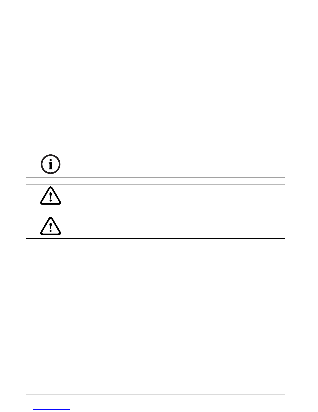
NOTICE!
Operational malfunction can be prevented and operational improvements can be achieved by
observing these instructions.
CAUTION!
This symbol warns against actions and behavior which, if disregarded, could cause property
damage.
WARNING!
This symbol warns against actions and behavior which, if disregarded, could cause personal
injury.

FCS-320-TM Aspirating Smoke Detector General | en 7
Bosch Sicherheitssysteme GmbH Operation Guide F.01U.130.928 | 1.0 | 2009.11
1.4 Copyright
The copyright to this operation guide remains with Bosch.
This operation guide is intended exclusively for installation engineers and their employees.
Reprinting this operation guide or extracts thereof is permitted for internal purposes only.
1.5 Disposal
CAUTION!
The equipment may only be installed by authorized and qualified personnel!
Unusable electrical and electronic devices or modules must not be disposed of with normal
household refuse. They must be disposed of in compliance with the applicable regulations and
directives (e.g. WEEE in Europe).

8 en | Technical Specifications FCS-320-TM Aspirating Smoke Detector
F.01U.130.928 | 1.0 | 2009.11 Operation Guide Bosch Sicherheitssysteme GmbH
2 Technical Specifications
2.1 Product Description
Aspirating smoke detectors from the FCS-320-TM series are active fire detection devices for
providing early smoke and fire detection. They are used for space and equipment protection
as well as for monitoring air conditioning units or ducts (provided that the FCS-320-TM is
installed outside of these units or ducts). You can also pinpoint the exact location of the fire
using the innovative fire source identification operation.
Variants
All FCS-320-TM series aspirating smoke detectors have LED displays for operating mode,
malfunction and main alarm, and also offer an infrared diagnostics port. In addition, the FCS320-TM-R variant offers an optical fire source identification display for up to five zones.
fire source identification
Innovative fire source identification technology allows the exact location of the fire to be
pinpointed by monitoring up to five distinct neighboring zones. To enable the emergency
response teams to intervene as quickly as possible, the location of the fire can also be
identified, for example, by means of strobes that are assigned to the various monitoring
ranges.
sensitivity
FCS-320-TM series aspirating smoke detectors have a response sensitivity of 0.5%/m to 2%/m
light obscuration.
With the new high-power light source technology, a broad detection spectrum including all
standardized fires is achieved (see Section 3.4 Defining the Response Sensitivity, page 35).
LOGIC·SENS
The intelligent signal processing LOGIC·SENS distinguishes between deception variables and
fire events in order to prevent false alarms.
Reliable airflow monitoring
Analogous to point-type smoke detectors, which are monitored electronically for wire breaks
and short-circuits, highly sensitive and dependable airflow monitoring is required for smoke
aspiration systems. The airflow sensors used in the FCS-320-TM series reliably detect
malfunctions such as pipe breakage or obstruction of the air sampling openings.
The airflow monitoring is temperature-compensated and can be set depending on the air
pressure.
Plug-and-play
The plug-and-play function makes the installation and commissioning of the aspirating smoke
detectors simple. The housing base is preinstalled on site. By presetting the detection unit for
standard applications, the FCS-320-TM series aspirating smoke detectors are ready for
operation as soon as they are inserted into the housing base.
Patented air sampling openings
The air sampling openings of the pipe system require clearly defined bore diameters that
depend on the planning and design. These precise air sampling openings are created using
patented aspiration reducing film sheets, marking tape, and clips, which not only permit easy
installation, but also prevent "whistling" noises. Another advantage is the quick and easy
detection and checking of the air sampling opening diameters.

FCS-320-TM Aspirating Smoke Detector Technical Specifications | en 9
Bosch Sicherheitssysteme GmbH Operation Guide F.01U.130.928 | 1.0 | 2009.11
Point-type detector projection
The system’s aspiration points can be equated with point-type smoke detectors. The
monitoring areas can therefore be planned in accordance with the applicable national
regulations.
Diagnostics
A system with FAS-ASD-DIAG Diagnostic Software, which enables quick and convenient error
containment, is available for maintenance and service. The current and stored (max. 72 hours)
unit status is read out to the diagnostic appliance via the unit's infrared port. The data is
transmitted from the diagnostic appliance to a laptop via a USB cable.
Selecting the fan voltage
The fan voltage can be increased from 9 V to 12 V for any special planning processes. In
addition, the fan voltage can be increased up to 13.5 V in intervals of 1 V via the
FAS-ASD-DIAG Diagnostic Software. The increase in the fan voltage causes an increase in the
air transport speed and therefore reduces detection time.
Extensive pipe accessories
The extensive range of accessories enables the FCS-320-TM aspirating smoke detectors to be
used even in the most difficult conditions. Products from air filters and condensate separators
to blowing-out systems increase the service life in extremely dusty, damp and cold
environmental conditions.
2.2 Areas of Application
Thanks to their detection principle, FCS-320-TM Aspirating Smoke Detectors provide an
extremely versatile fire alarm system.
Principle
Air samples are taken from the monitoring range by a pipe system with defined aspiration
borings and then fed to the detection unit.
This is especially well-suited for areas in which point-type detectors cannot be used or can
only be used under certain circumstances. These include:
– Areas that are difficult to access, in which point detectors are difficult to install and
maintain
– Air-conditioned areas
– Areas that require the earliest detection possible
– Areas with a height greater than that allowed for point detectors
– Areas in which point detectors are not desired for aesthetic reasons
– Areas in which strong electromagnetic fields occur
– Areas that are exposed to high or low temperatures
– Areas with contaminated air that require filter elements
– Areas that must be protected against vandalism.
Space protection
The FCS-320-TM series is suitable for monitoring areas such as
– Those with double floors, false ceilings
– Tunnels, ducts, barely accessible hollow spaces
– Storage, high-rise warehouses, elevator shafts
– Museums, cultural institutions
– Hotel rooms, hospital rooms, offices, prison cells, train compartments
10 en | Technical Specifications FCS-320-TM Aspirating Smoke Detector
F.01U.130.928 | 1.0 | 2009.11 Operation Guide Bosch Sicherheitssysteme GmbH
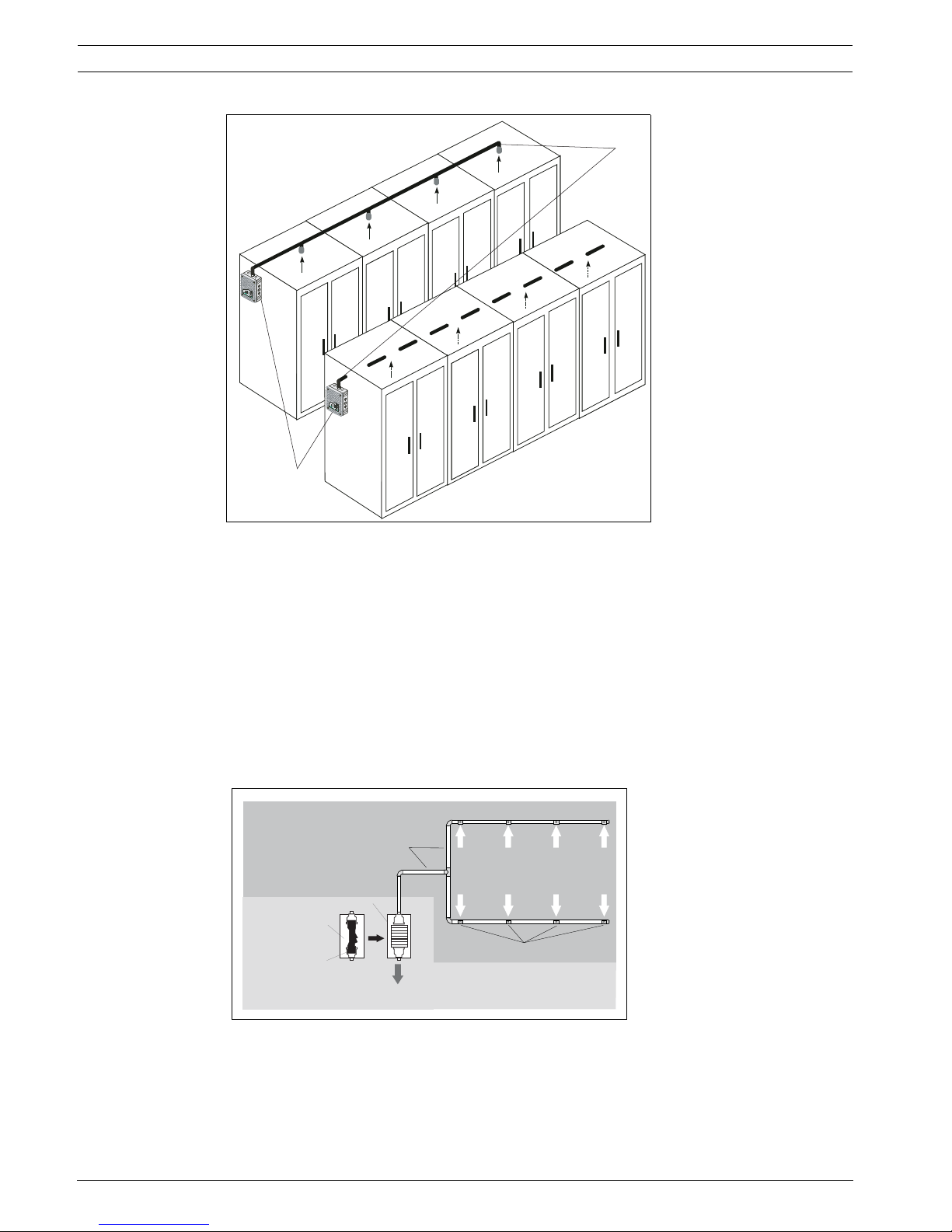
Area monitoring with air-conditioning
Area monitoring occurs
– In rooms with air-conditioning for service rooms etc.
– In ventilation ducts
– In double floors, false ceilings
– In IT rooms, e-distributor rooms, transformer cells
– On air-conditioning units (Figure 2.2) or
– In the bypass in air-conditioning ducts.
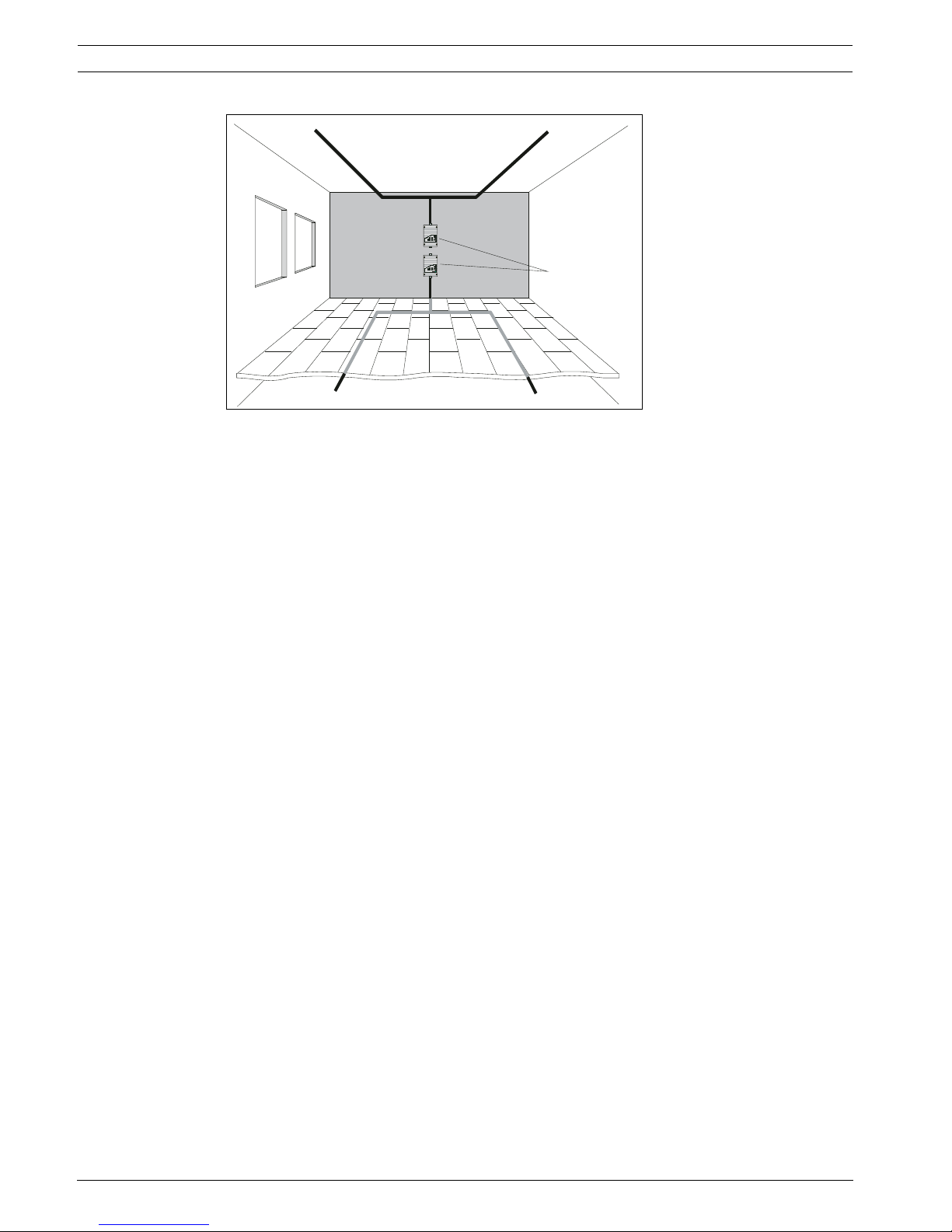
Figure 2.1 Principle of area monitoring with FCS-320-TM series aspirat-
ing smoke detectors
1 Room pipe system
2 Double-floor pipe system
FAS / FCS
1
2
TITANUS MICRO·SENS ®
E
D
C
B
A
10
9
8
7
6
5
4
3
2
1
TITANUS MICRO·SENS ®
E
D
C
B
A
10
9
8
7
6
5
4
3
2
1
FCS-320-TM Aspirating Smoke Detector Technical Specifications | en 11
Bosch Sicherheitssysteme GmbH Operation Guide F.01U.130.928 | 1.0 | 2009.11
The FCS-320-TM Aspirating Smoke Detector can be used for early fire detection in areas with
special-purpose air conditioning.
Thanks to its high sensitivity, expensive goods and equipment can be monitored reliably. The
aspirating smoke detectors from the FCS-320-TM series are therefore especially suitable for
areas of application:
– Where early intervention is essential due to a high value concentration
– Where equipment must always be operational
– Where highly sensitive detection is necessary (e.g. in areas where, due to built-in filter
elements, the air contains a low concentration of smoke particles)
– Where high air-exchange rates prevail.
Equipment protection
Equipment monitoring involves the direct monitoring of an object. These can be unventilated
or force-cooled units or cabinets, e.g.
– Distributor cabinets, switching cabinets
– Telephone-switching equipment
– Measuring, control, and regulation equipment.
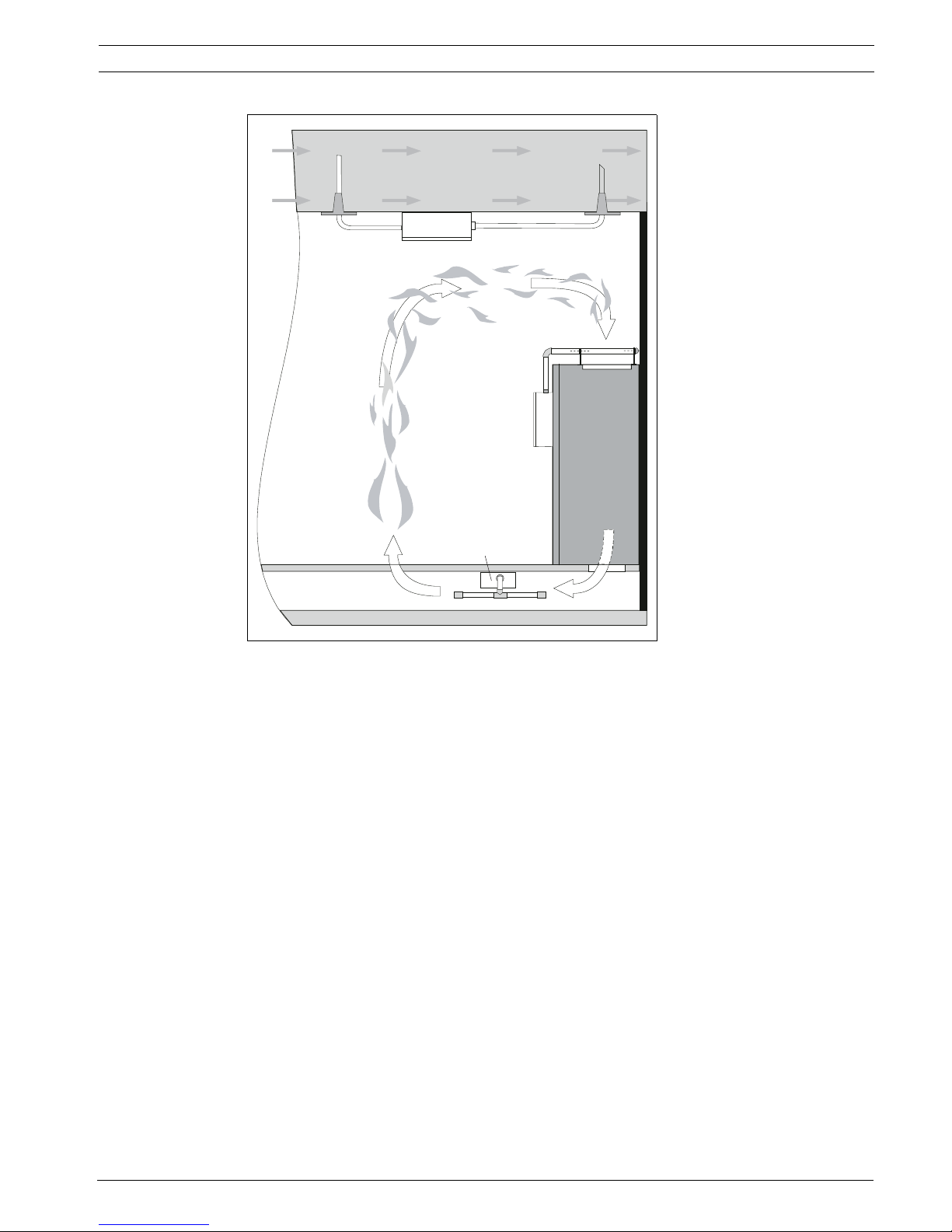
Figure 2.2 Monitoring options for an air-conditioning unit or an air-
conditioning duct (depiction of principle)
1 air-conditioning duct
2 Air-conditioning unit
FAS / FCS
FAS / FCS
FAS / FCS
1
2
12 en | Technical Specifications FCS-320-TM Aspirating Smoke Detector
F.01U.130.928 | 1.0 | 2009.11 Operation Guide Bosch Sicherheitssysteme GmbH
2.3 System Overview
The Smoke Aspiration Systems comprise a detection unit, housing base and pipe system.
The most important components of the Smoke Aspiration System are the sensitive detection
unit for detecting smoke aerosols and the aspiration unit with the built-in airflow sensor for
transporting the air samples and monitoring the pipe system for breakage and obstructions.
The pipe system comprises essentially pipe and fittings. The standard pipe system is made
from PVC or ABS. The pipes used for equipment monitoring should be halogen-free.
Each air sampling opening in the pipe system represents a point detector in the planning.
To guarantee reliable operation even under the most difficult conditions (clean rooms,
recycling area), there are numerous accessories available, such as air filters and water
separators; see Section 2.6 Pipe system components, page 21.
Figure 2.3 Principle of equipment monitoring with FCS-320-TM series
aspirating smoke detectors
1Clicking
1
FAS / FCS
Figure 2.4 Overview of the aspirating smoke detector
A Pipe System
FAS/FCS aspirating smoke
detector
1Smoke aspiration
pipe
2 Air intake
3 Air sampling
openings
4 Detection unit incl.
airflow sensor
5 Housing Base
6 Aspiration unit
7air outlet
2
7
3
1
A
FAS / FCS
4
6
5
FCS-320-TM Aspirating Smoke Detector Technical Specifications | en 13
Bosch Sicherheitssysteme GmbH Operation Guide F.01U.130.928 | 1.0 | 2009.11
2.4 Functions
Air samples are taken from the area to be monitored via the aspiration unit. They are fed via a
pipe system with defined air sampling openings to the sensitive detection unit (see
Figure 2.4).
Detection
Depending on the response sensitivity of the detection unit in use and the alarm threshold
programmed, the FCS-320-TM aspirating smoke detector triggers the alarm when the
corresponding air obscuration threshold is reached. The alarm is displayed via the main alarm
LED on the device and transmitted to a connected fire panel.
Various delay times can be set for the alarm thresholds, as well as for displaying and
transferring malfunctions. Alarm messages are saved and are reset after the cause has been
eliminated.
LOGIC·SENS
The LOGIC·SENS intelligent signal processing compares the measured smoke level with known
disturbance variables and decides whether something is an alarm or deception. LOGIC SENS
can be activated or deactivated using the fire panel's programming software.
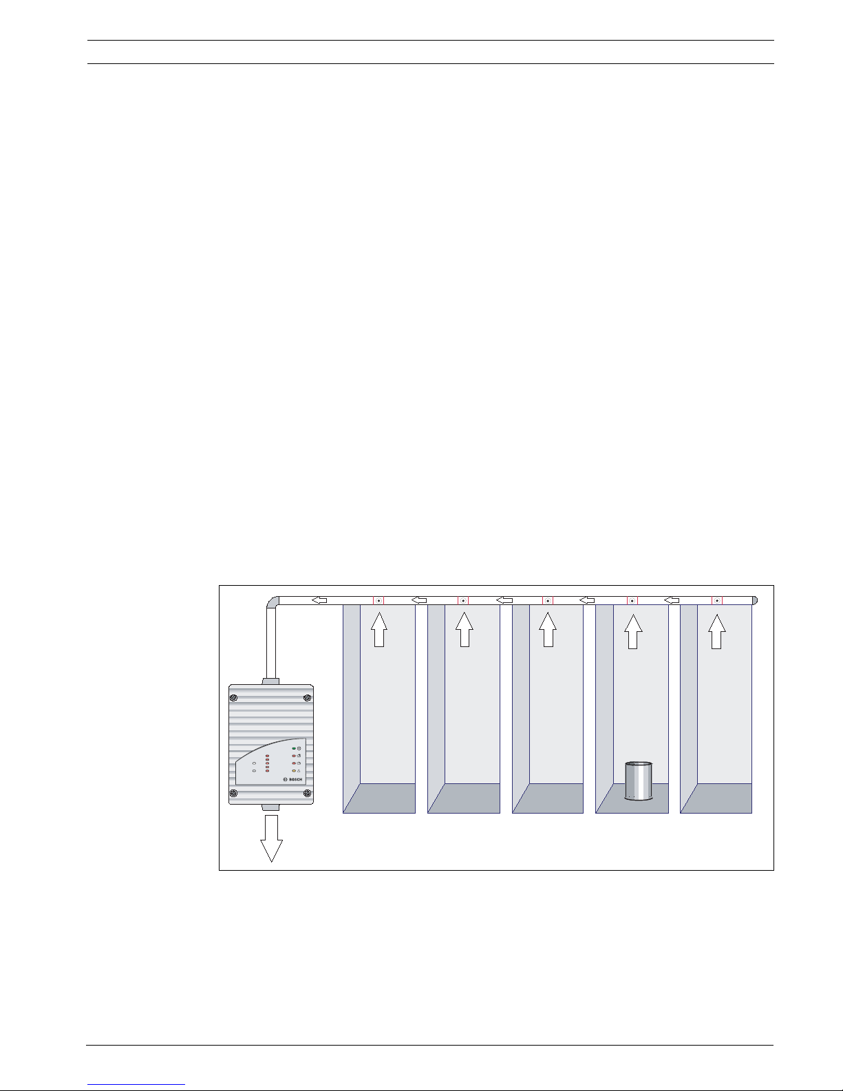
fire source identification
Fire source identification is possible if an I pipe is planned for a maximum of five areas or
devices. The procedure can be divided into four phases (Figure 2.5 to Figure 2.8).
– Phase 1
In its general operating state, the FCS-320-TM-R aspirating smoke detector extracts air
samples from the monitoring range and analyzes these for the presence of smoke
particles.
Figure 2.5 Phase 1: Normal operation
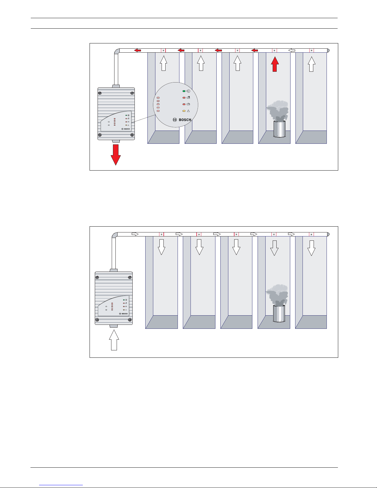
– Phase 2
As soon as the system has switched to alarm state as a result of a rise in the
concentration of smoke particles typical of a fire, the alarm is signaled.
E
D
C
B
A
FAS-420-TMseries
14 en | Technical Specifications FCS-320-TM Aspirating Smoke Detector
F.01U.130.928 | 1.0 | 2009.11 Operation Guide Bosch Sicherheitssysteme GmbH
Figure 2.6 Phase 2: Early fire detection
– Phase 3
When the alarm is signaled, once the configurable pre-alarm threshold is reached, the
aspiration fan switches off and a second fan blows all smoke particles out of the pipe
system in the opposite direction.
Figure 2.7 Phase 3: Blowing out
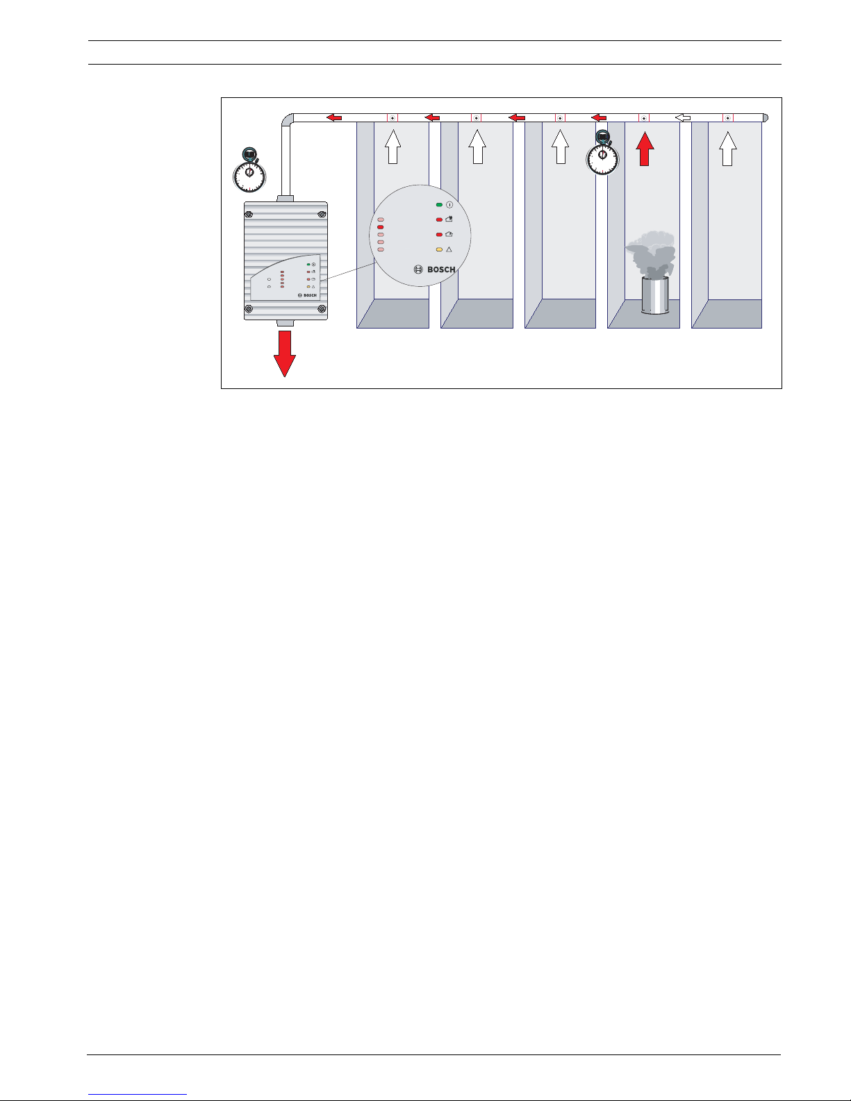
– Phase 4
Once the pipe system has been blown out, the direction of flow is reversed again and the
time required for the smoke particles to penetrate into the detection unit is measured.
On the basis of this time, the location of the smoke source can be accurately traced to
one of the monitored areas.
E
D
C
B
A
FAS-420-TMseries
E
D
C
B
A
E
D
C
B
A
FAS-420-TMseries
FCS-320-TM Aspirating Smoke Detector Technical Specifications | en 15
Bosch Sicherheitssysteme GmbH Operation Guide F.01U.130.928 | 1.0 | 2009.11
Figure 2.8 Phase 4: Identification of fire source by reversing the fan's direction of flow
Once the fire source has been identified, it is displayed via a corresponding display on the
FCS-320-TM-R.
Detection
Depending on the response sensitivity set on the detector module (0.5%/m to 2%/m light
obscuration), the FCS-320-TM-R triggers the main alarm when the appropriate light
obscuration is reached. The sensitivities can also be set at intervals of 0.1%/m using the
FAS-ASD-DIAG diagnostic software. The alarm is displayed via the alarm display on the unit
and forwarded to the fire panel connected. The alarm thresholds and the display and
transmission of malfunctions can be allocated different delay times. The intelligent
LOGIC·SENS signal processing hides misleading values that are similar to those shown in the
event of a fire, and ensures a high level of security against deceptive alarms.
Alternative sensitivity
The FAS-ASD-DIAG diagnostic software allows the sensitivity set on the detection unit to be
changed if necessary.
Monitoring unit
The detection unit is monitored for contamination and for signal malfunction. A malfunction is
displayed on the unit and forwarded to the fire panel. Malfunctions caused by brief
environmental fluctuations can be eliminated with a time-delayed setting.
Airflow monitoring
An airflow sensor checks the connected pipe system for breakage and obstruction.
The airflow sensor can – depending on the configuration of the pipe system (see
Section 3.2 Principles of Pipe Planning, page 32) and the setting of the airflow sensors - detect
an obstruction of a single air sampling opening. The airflow monitoring is temperaturecompensated and can be set depending on the air pressure.
On expiry of a defined delay, the malfunction is displayed on the aspirating smoke detector
and the message is transmitted to the fire panel. The monitoring window thresholds can be
modified to suit the environmental conditions (see Section 3.3 Airflow monitoring, page 34).
The principal signal curve of the airflow sensor is indicated in Figure 2.9.
E
D
C
B
A
FAS-420-TMseries
E
D
C
B
A

16 en | Technical Specifications FCS-320-TM Aspirating Smoke Detector
F.01U.130.928 | 1.0 | 2009.11 Operation Guide Bosch Sicherheitssysteme GmbH
Calibrating the Airflow Sensor
The airflow sensor calibration of the FCS-320-TM Aspirating Smoke Detector is performed
automatically when the detection unit is inserted into the housing base, provided that the X4
jumper has been plugged into another socket first. This plug-and-play feature makes the FCS320-TM considerably easier to commission. In addition, the calibration can also be performed
using the FAS-ASD-DIAG Diagnostic Software. The initialization phase is therefore carried out
according to or independently of the air pressure as desired.
Pipe System
A pipe system with an overall length of up to 50 m can be connected to FCS-320-TM series
Aspirating Smoke Detectors over a maximum of 8 aspiration points. A maximum of 5
aspiration points can be connected with ROOM·IDENT.
Figure 2.9 Example of the signal process of the airflow sensor in
case of malfunctions
S Airflow sensor signal
tTime
1 Normal airflow
2Airflow too weak
3 Airflow too strong
4 Breakage
5obstruction
6 Monitoring window
7 Delay
8 Malfunction message
S
t
4
7
8
6
1
2
5
3
FCS-320-TM Aspirating Smoke Detector Technical Specifications | en 17
Bosch Sicherheitssysteme GmbH Operation Guide F.01U.130.928 | 1.0 | 2009.11
2.5 FCS-320-TM Series Aspirating Smoke Detectors and
Accessories
2.5.1 Overview
FCS-320-TM series aspirating smoke detectors comprise the following components:
Housing Base
– Connections for pipe with 25 mm external diameter (input and return)
– Pack with cable entries, 1 x M 25 (for cable diameter of 1-18 mm) and
2 x M 20 (for cable diameter of 1-13 mm)
– Screw terminals for securing cables with a thickness of up to 2.5 mm²
detection unit
– Sensitive detection with the latest technology according to the principle of an optical
scattered-light smoke detector with integrated airflow monitoring
– Aspiration unit with optimized air routing
– Infrared diagnostics port
– FCS-320-TM: optical displays for main alarm, malfunction and operation
– FCS-320-TM-R: optical displays for fire source identification, main alarm, malfunction and
operation
Information on other accessories for special applications can be found in
– Section 2.5.5 FAS-ASD-DIAG Diagnostic Software
– Section 2.6.3 Ceiling Lead-through Adapter
– Section 2.6.5 Water Separator for Humid Areas
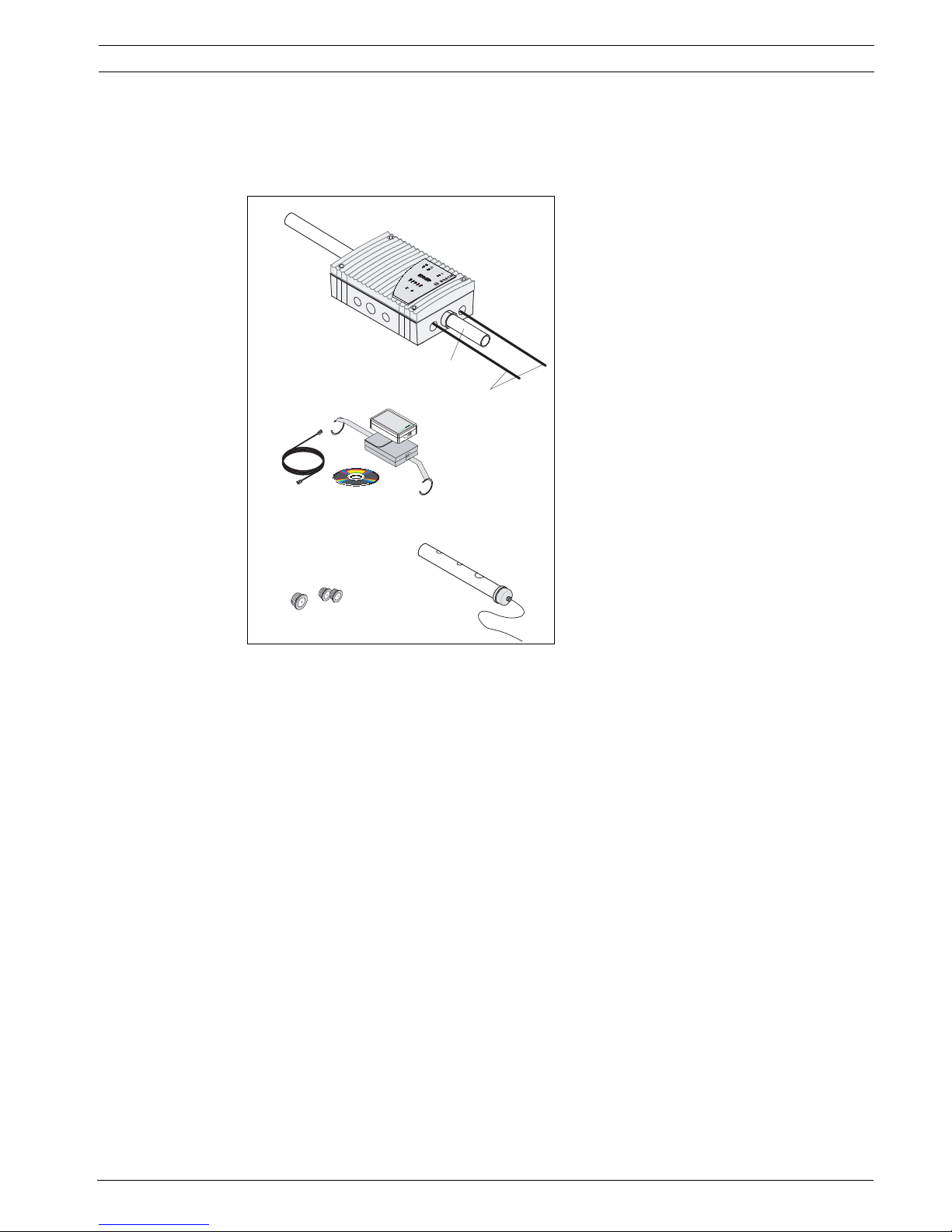
Figure 2.10 Overview of FCS-320-TM series aspirat-
ing smoke detectors and accessories
1 Pipe System
2 Connections to fire panel/power supply
3 Air-return Pipe
A FAS-ASD-DIAG Diagnostic Software with
connection cable
B Cable entries (2 x M20, 1 x M25)
C Test pipe
1
2
3
A
BC
F
AS
-4
20
-
TM
se
ries

18 en | Technical Specifications FCS-320-TM Aspirating Smoke Detector
F.01U.130.928 | 1.0 | 2009.11 Operation Guide Bosch Sicherheitssysteme GmbH
2.5.2 FCS-320-TM series connections
Figure 2.11 FCS-320-TM connections (see table below for explanations)
FCS-320-TM
series
Position in
Figure 2.11
Function Explanation
1 Connection for aspiration pipe For ∅ 25 mm pipe
system
2 Connection for air return pipe For ∅ 25 mm pipe
system
3 Cable bushing for connection of fire
panel and additional power supply
(input/output)
2 x M 25
4 Cable bushing for connection of fire
panel and additional power supply
(input/output)
8 x M 20
F
A
S
-420
-
T
M
se
ries
F
A
S
-420-T
M
ser
ies
2
1
3
3
4
4
4
4
4
4
4
4
NOTICE!
When using fire source identification, it is not permitted to connect an air-return pipe.

FCS-320-TM Aspirating Smoke Detector Technical Specifications | en 19
Bosch Sicherheitssysteme GmbH Operation Guide F.01U.130.928 | 1.0 | 2009.11
2.5.3 FCS-320-TM displays
Figure 2.12 FCS-320-TM displays
2.5.4 FCS-320-TM-R displays
Figure 2.13 FCS-320-TM-R displays
FCS-320-TM Display LED Explanation
Operation Green Operation display
Main alarm Red Main alarm display
Malfunction Yellow Malfunction
– in the pipe system
– in the detection unit
–caused by fan failure
Infrared port Fault diagnosis
FCS-320-TM-R Display LED Explanation
Operation Green Operation display
Main alarm Red Main alarm display
Malfunction Yellow Malfunction
– in the pipe system
– in the detection unit
–caused by fan failure
Fire source
identification for zones
A-E
5 red
LEDs
fire source identification
Infrared port Fault diagnosis
E
D
C
B
A
20 en | Technical Specifications FCS-320-TM Aspirating Smoke Detector
F.01U.130.928 | 1.0 | 2009.11 Operation Guide Bosch Sicherheitssysteme GmbH
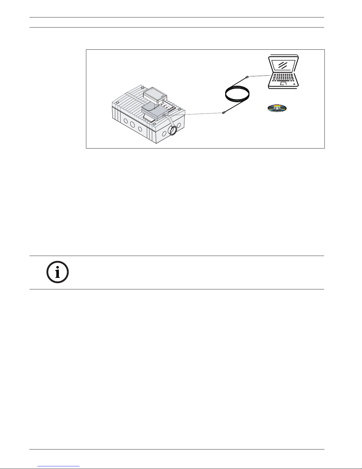
2.5.5 FAS-ASD-DIAG Diagnostic Software
Figure 2.14 Diagnostic software for importing and reading out the device data
The FAS-ASD-DIAG Diagnostic Software enables the saved and current statuses of the
FCS-320-TM and error messages to be saved on a PC or laptop.
Data is transmitted to the diagnostic appliance via the infrared port of the aspirating smoke
detector. The USB cable provided is used to transmit the data from the diagnostic appliance
to the PC/laptop (see Figure 2.14).
Windows 2000 or Windows XP can be used as the operating system. For correct color display,
the monitor and graphics card must be able to display more than 256 colors.
Diagnostic messages remain saved in the FCS-320-TM for at least 3 days in order to be able to
evaluate even short, sporadically occurring errors (e.g. in case of changed operating
conditions).
Resetting the FCS-320-TM via the diagnostic software deletes all saved diagnostic messages.
The software also allows the deletion of error messages.
2.5.6 External Detector Alarm Displays
A remote indicator must be connected if the aspirating smoke detector is not directly visible
or has been mounted in false ceilings or floors.
The external detector alarm display is installed in an obvious place in halls or entrances of the
building section or areas concerned.
Remote indicators can be actuated via the optional relay board. If FNS-320-TM-R variants with
fire source identification are used, the remote indicators are assigned to the various
monitoring ranges by the relay board and, in the event of a fire, identify the location of the
fire.
FAS-
DIAG
NOTICE!
The diagnostic software can be used to save in file format all stored and current diagnostics
data and any settings made via the fire panel programming software. To be able to compare
the data read out, save each file under a different file name.
FCS-320-TM Aspirating Smoke Detector Technical Specifications | en 21
Bosch Sicherheitssysteme GmbH Operation Guide F.01U.130.928 | 1.0 | 2009.11
2.6 Pipe system components
2.6.1 Overview
During planning/design, a distinction is drawn between area monitoring and equipment
monitoring. For both applications, PVC pipes and halogen-free pipes can be used. The pipes
used for equipment monitoring should be halogen-free.
Figure 2.15 shows essential accessory components that can be selected for the application
concerned.
The pipe system must be constructed using pipes with an external diameter of 25 mm and the
associated fittings.
blowing-out system
In areas that are susceptible to dust particles or icing, it may be necessary to blow out the
aspiration pipe system and its air sampling openings. Figure 2.16 shows a manual blowing-out
system with a three-way tap.
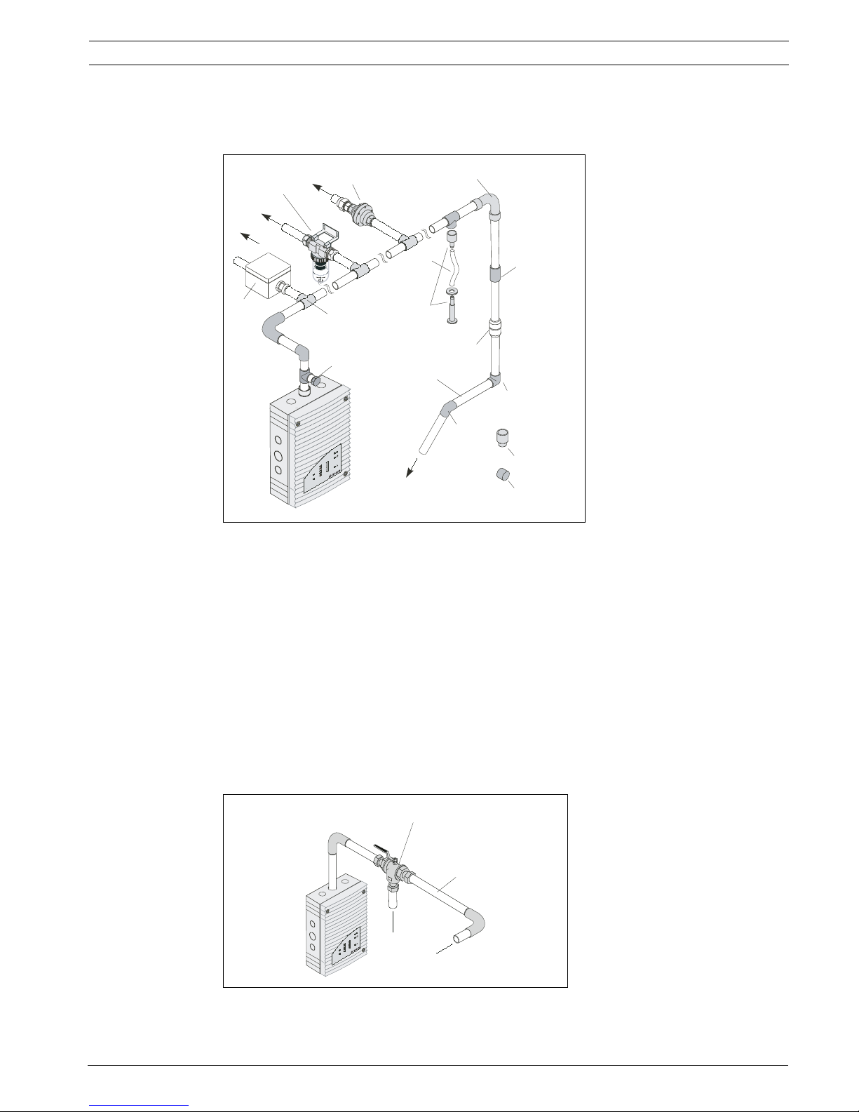
Figure 2.15 Pipe system components
A Pipe system connection
B Smoke aspiration pipe
1 Connection for test adapter
2T-fitting
3 Air filter
4Water separator
5 Detonation safety barrier
(not permitted for EN 54-20)
6 90° pipe bend
7 Aspiration hose for ceiling
lead-through
8 Ceiling Lead-through
Adapter
9fitting
10 Double threaded joint
11 90° pipe elbow
12 45° pipe elbow
13 Aspiration reduction
14 End cap
Figure 2.16 Components of manual blowing-out systems
A Blast air supply connection
B Pipe system connection
1 Three-way tap
2 25 mm aspiration pipe
Aspiration reducing clips
F
A
S-4
2
0
-
T
M
s
e
r
ie
s
A
A
A
4
5
3
2
7
6
8
9
10
11
12
13
1
14
A
B
F
A
S
-4
2
0
-T
M
s
e
ri
e
s
A
1
2
B
22 en | Technical Specifications FCS-320-TM Aspirating Smoke Detector
F.01U.130.928 | 1.0 | 2009.11 Operation Guide Bosch Sicherheitssysteme GmbH
2.6.2 Air sampling openings
Aspiration reducing film sheets
An air sampling opening is a 10 mm bore in the aspiration pipe that is covered with a patented
aspiration reducing film sheet with the required opening diameter. The size of the opening
depends on the structure of the pipe system (see Section 3 Planning, page 31).
The aspiration reducing film sheet is secured with marking tape to prevent it from becoming
displaced. The marking tape is a transparent sticky film with red edges and a 10 mm hole. It is
placed over the aspiration reducing film sheet so that the air sampling opening is not
concealed and can be seen from long distances.
Aspiration reducing clips
In areas susceptible to obstructions or icing, special, patented ASD aspiration clips with
flexible aspiration reductions are used (see Figure 2.18).
During use in deep-freeze areas, the flexible aspiration reduction expands in the air sampling
openings and pushes the ice away during blowing out. The special plastic clip ensures that the
aspiration reduction remains at the defined location.
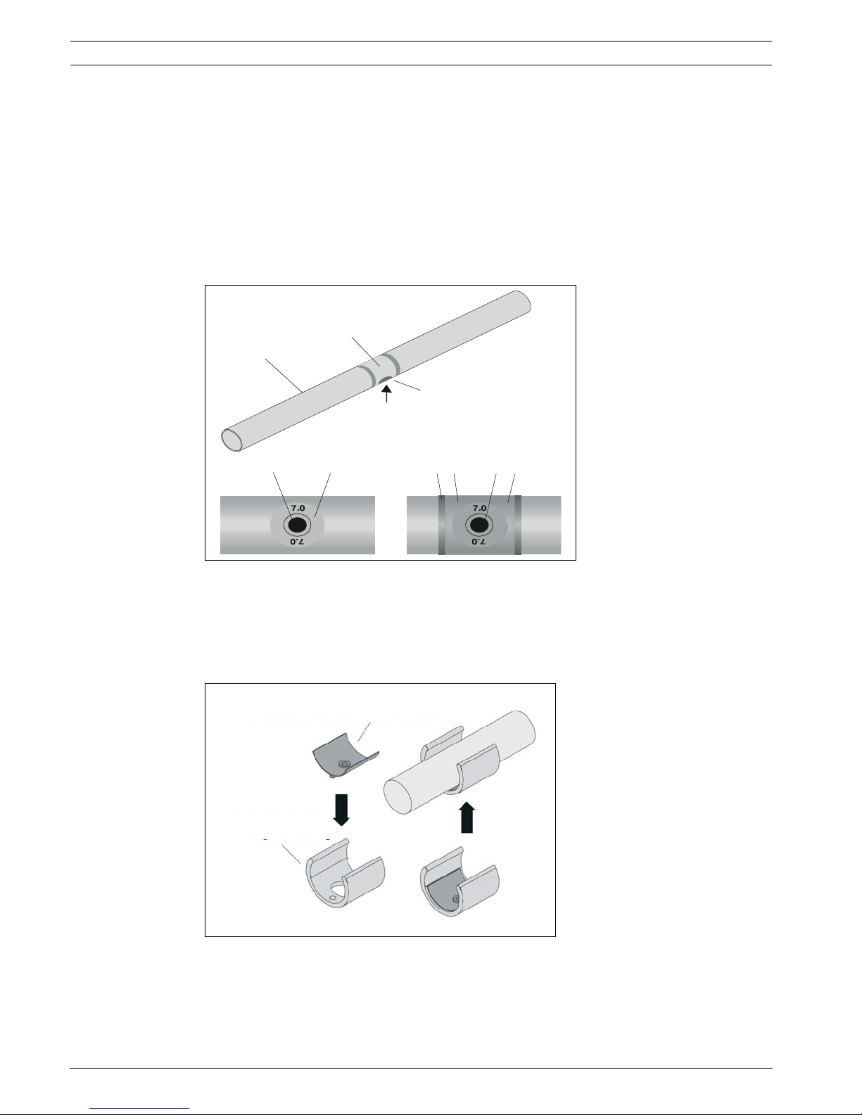
Figure 2.17 Air sampling opening with aspiration reducing film sheet
and marking tape
1 Smoke aspiration pipe
2 Air sampling opening with
aspiration reducing film
sheet
3 Marking tape for aspiration
reducing film sheet
4 Air sampling opening
5 Fire red (RAL 3000)
6 Transparent
Figure 2.18 Aspiration reduction for soiled areas and deep-freeze
areas
1 Aspiration reduction for deep-
freeze facilities
2 ASD aspiration clip made of
plastic
1
3
36
2
4
4
45
2
1
2
FCS-320-TM Aspirating Smoke Detector Technical Specifications | en 23
Bosch Sicherheitssysteme GmbH Operation Guide F.01U.130.928 | 1.0 | 2009.11
As the clips are more stable under pressure and the elastic rubber insert significantly
improves the cleaning effect, they are used for all plans and designs which require a blow-off
system due to environmental influences (e.g. increased exposure to dust).
The aspiration reductions with plastic clips are available separately.
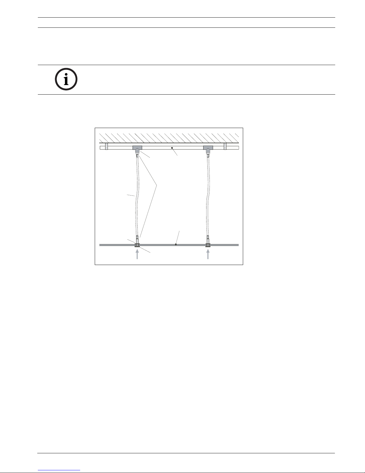
2.6.3 Ceiling Lead-through Adapter
A concealed pipe system for area monitoring can be realized by installing in a false ceiling.
This requires the use of ceiling lead-throughs in the false ceiling. The ceiling lead-through can
be used with a false ceiling thickness of up to approx. 35 mm. In line with the planning and
design guidelines, the ceiling lead-throughs are fitted with aspiration reducing film sheets
with defined air sampling openings and connected to the pipe system by means of aspiration
hoses (see Figure 2.19).
If these hoses do not exceed a maximum of 3 m, the plan according to Section 3 Planning,
page 31 applies. If structural circumstances dictate that lengths in excess of 3 m are used, the
pipe system has to be calculated accordingly.
NOTICE!
The standard AF-x aspiration reducing film sheets and the marking tapes are not suitable for
use in low-temperature areas.
Figure 2.19 Ceiling lead-through adapters
1Ceiling
2T-fitting
3 Pipe System
4 Complete ceiling lead-through
5 Aspiration hose for ceiling
lead-through
6false ceiling
7 Knurled nut
8 Aspiration reducing film sheet
9Aspiration
1
2
3
4
6
7
8
9
5
24 en | Technical Specifications FCS-320-TM Aspirating Smoke Detector
F.01U.130.928 | 1.0 | 2009.11 Operation Guide Bosch Sicherheitssysteme GmbH
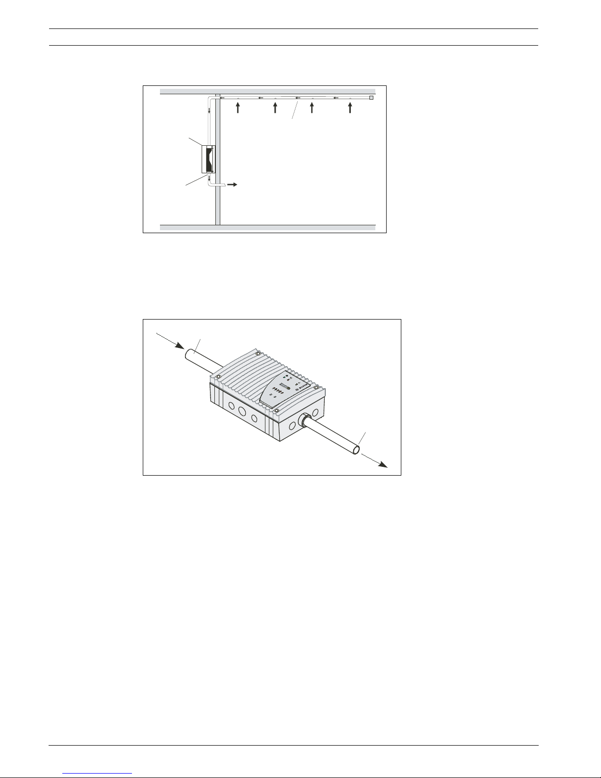
2.6.4 Air-Return Pipe for Pressure Areas and Atmospheric Loads
If the aspirating smoke detectors and the pipe system are installed in areas with varying air
pressure, the aspirated air must be returned to the pressure area of the pipe system (see
Figure 2.20). The air-return pipe can serve to equalize pressure or to prevent atmospheric
loads (e.g. odors) in neighboring spaces.
The air-return pipe is installed in the conical pipe connection for the air return of the FCS-320TM (see Figure 2.21). It fits perfectly in the connection and guarantees a firm hold. When
using fire source identification, it is not permitted to connect an air-return pipe.
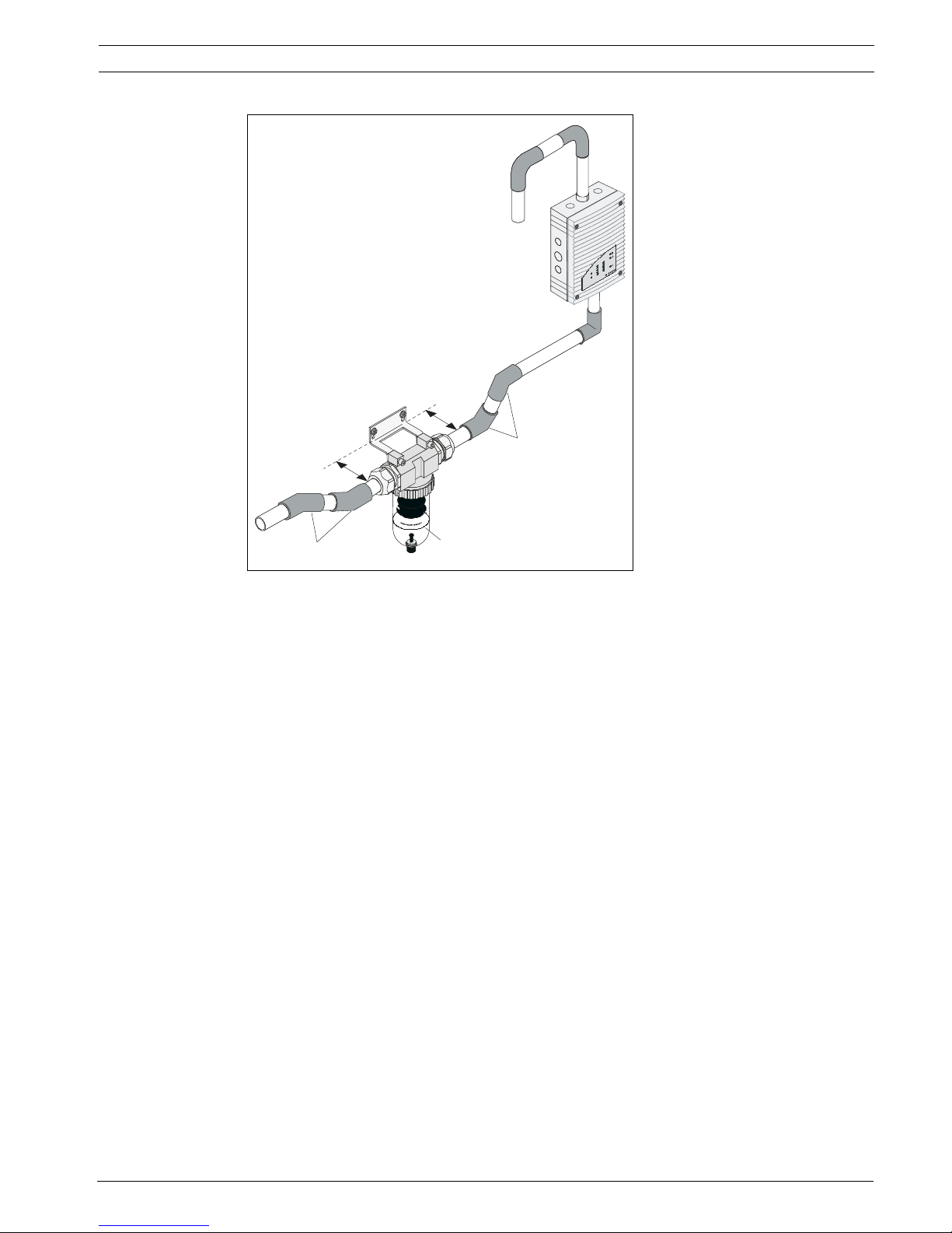
2.6.5 Water Separator for Humid Areas
If the smoke aspiration system is operated in environments where condensate can form in the
aspiration system, a water separator is used. Condensate can form with sharp temperature
fluctuations and in areas where fresh air is monitored. For areas with extremely high humidity,
the FAS-ASD-WS Water Separator can be used, for example.
The FAS-ASD-WS Water Separator is integrated at the lowest point in the pipe system
downstream of the air filter and the aspirating smoke detector. The 45° pipe elbow permits
optimum distance from the wall (see Figure 2.22).
Figure 2.20 Principle of air return
P1/P2 Pressure areas 1 and 2
1 Air-return Pipe
2 Pipe System
Figure 2.21 FCS-320-TM with air return
1 Smoke aspiration pipe
2 Air-return Pipe
2
FAS / FCS
1
P1
P2
F
A
S
-4
20
-
T
M
se
rie
s
2
1
FCS-320-TM Aspirating Smoke Detector Technical Specifications | en 25
Bosch Sicherheitssysteme GmbH Operation Guide F.01U.130.928 | 1.0 | 2009.11
The FAS-ASD-WS Water Separator can be operated in a temperature range from 0 °C to
+50 °C. The sintered metal filter in the water separator has a pore width of 50 µm and causes
an additional rough absorption of soil particles.The FAS-ASD-WS is supplied with an angle
support and PG cable glands. The 45° pipe elbows (4 units) must be ordered separately.
Figure 2.22 FAS-ASD-WS Water Separator for condensing water
vapor and collecting condensate from the pipe system
1water separator
2 Pipe system connection
3 45° pipe elbow
1
2
3
3
FAS-420-TM seri
es

26 en | Technical Specifications FCS-320-TM Aspirating Smoke Detector
F.01U.130.928 | 1.0 | 2009.11 Operation Guide Bosch Sicherheitssysteme GmbH
2.7 Scope of Delivery: Smoke Aspiration System
Basic devices and accessories
Pipe system components
Designation Order number
FCS-320-TM Standard unit F.01U.141.195
FCS-320-TM-R Standard unit F.01U.141.196
FAS-420-TM-HB Housing Base F.01U.078.394
FAS-ASD-DIAG Diagnostic Software including connection cable, for
USB port
F.01U.033.505
FCA-320 relay Relay board F.01U.141.200
FCA-320 reset Reset board F.01U.141.199
RAS Test Pipe Test pipe 4.998.148.848
RAS Test Adapter Test Adapter 4.998.148.849
Designation Order number
FAS-ASD-PHF16 Polywell aspiration hose, flexible, black, halogen-
free
F.01U.029.719
FAS-ASD-TRPG16 Ring nut with PG16 internal thread, 5 per set F.01U.029.721
FAS-ASD-CSL Quick-lock coupling, straight, PG16 internal thread F.01U.029.720
FAS-ASD-3WT Three-way tap, incl. fittings, for 25 mm pipe system F.01U.029.718
FAS-ASD-F Flange for ventilation duct F.01U.029.722
FAS-ASD-AR Aspiration reduction, with 10 mm bore for attaching
an aspiration reducing film sheet, 10 per set
F.01U.029.724
FAS-ASD-CLT Ceiling lead-through, white, ABS, 10 per set F.01U.029.725
FAS-ASD-AHC Aspiration hose (PE) for ceiling lead-through F.01U.029.727
FAS-ASD-WS Water Separator with sintered metal filter and
manual drain valve, including mounting bracket and
PG cable glands for 25 mm pipe system
F.01U.029.717
FAS-ASD-FL Large air filter box, for 25 mm pipe system, inc. 1
filter set and two PG29 screw connections
F.01U.029.714
FAS-ASD-RFL Replacement filter set for large air filter box F.01U.029.715
NOTICE!
Four 45° pipe elbows are required to install the FAS-ASD-WS Water Separator.

FCS-320-TM Aspirating Smoke Detector Technical Specifications | en 27
Bosch Sicherheitssysteme GmbH Operation Guide F.01U.130.928 | 1.0 | 2009.11
Air Sampling Opening Components
Designation Order number
Marking tape for aspiration reducing film sheet AF-BR, 10 units. 4.998.143.413
Aspiration reducing film sheet 2.0 mm AF-2.0, 10 units. 4.998.143.416
Aspiration reducing film sheet 2.5 mm AF-2.5, 10 units. 4.998.143.417
Aspiration reducing film sheet 3.0 mm AF-3.0, 10 units. 4.998.143.418
Aspiration reducing film sheet 3.2 mm AF-3.2, 10 units. 4.998.143.419
Aspiration reducing film sheet 3.4 mm AF-3.4, 10 units. 4.998.143.420
Aspiration reducing film sheet 3.6 mm AF-3.6, 10 units. 4.998.143.422
Aspiration reducing film sheet 3.8 mm AF-3.8, 10 units. 4.998.143.423
Aspiration reducing film sheet 4.0 mm AF-4.0, 10 units. 4.998.143.424
Aspiration reducing film sheet 4.2 mm AF-4.2, 10 units. 4.998.143.425
Aspiration reducing film sheet 4.4 mm AF-4.4, 10 units. 4.998.143.426
Aspiration reducing film sheet 4.6 mm AF-4.6, 10 units. 4.998.143.427
Aspiration reducing film sheet 5.0 mm AF-5.0, 10 units. 4.998.143.428
Aspiration reducing film sheet 5.2 mm AF-5.2, 10 units. 4.998.143.429
Aspiration reducing film sheet 5.6 mm AF-5.6, 10 units. 4.998.143.430
Aspiration reducing film sheet 6.0 mm AF-6.0, 10 units. 4.998.143.431
Aspiration reducing film sheet 6.8 mm AF-6.8, 10 units. 4.998.143.432
Aspiration reducing film sheet 7.0 mm AF-7.0, 10 units. 4.998.143.433
NOTICE!
Plastic clips with marking tape for deep-freeze facilities and blowing-out systems are sold
separately.

28 en | Technical Specifications FCS-320-TM Aspirating Smoke Detector
F.01U.130.928 | 1.0 | 2009.11 Operation Guide Bosch Sicherheitssysteme GmbH
2.8 Technical data
2.8.1 FCS-320-TM series aspirating smoke detector
Electrical
Mechanics
Environmental conditions
Auxiliary power supply 15 V DC-30 V DC
Current consumption from auxiliary power
supply
Fan voltage
9 V 10.5 V 12 V
– starting current 150 mA
– In standby 90 mA 110 mA 130 mA
– at Alarm 125 mA 135 mA 150 mA
Displays in the FCS-320-TM unit
– Operation Green LED
– Malfunction yellow LED
– Alarm 1 red LED for main alarm
– infrared port IR transmitter/receiver
Displays in the FCS-320-TM-R unit
– Operation Green LED
– Malfunction yellow LED
– Alarm 1 red LED for main alarm
– Fire location display 5 red LEDs (for zones A-E)
– infrared port IR transmitter/receiver
Conical duct connections for Ø 25 mm
– Aspiration pipe 1 pipe
– Air-return Pipe 1 pipe
Cable bushings
– Housing base sides 8 x M 20 and 2 x M 25
– Housing base rear wall 4 x M 25
Dimensions (HxWxD) 222x140x70mm
Weight Approx. 0.8 kg
Housing material Plastic (ABS)
Housing color Papyrus white (RAL 9018)
Protection category according to EN 60529
– Without air return IP 20
– With pipe section 100 mm/pipe bend IP 42
– With air return IP 54
Permissible temperature range of aspirating
smoke detector
-20°C to +60°C
Permissible relative humidity (non-condensing) Max. 95%

FCS-320-TM Aspirating Smoke Detector Technical Specifications | en 29
Bosch Sicherheitssysteme GmbH Operation Guide F.01U.130.928 | 1.0 | 2009.11
Special features
2.8.2 Pipe System
2.8.3 Smoke Aspiration System Components
Water separator (FAS-ASD-WS)
Filterbox, large (FAS-ASD-FL)
Replacement filter set, large (FAS-ASD-RFL)
Sound power level (at 9 V fan voltage) 40 dB(A)
Response sensitivity (light obscuration) 0.5 to 2.0%/m
Life cycle of fan (at 12 V and 24 °C) 60,000 hrs
Maximum pipe length Ø 25 mm 50 m
Additional maximum pipe length Ø 12 mm 8 x 3 m
Maximum number of air sampling openings 8
Maximum length of aspiration hose per
ceiling lead-through
3 m
Maximum size of monitoring area
400 m
²
Permissible temperature range
– PVC pipe system 0 °C to +60 °C
– ABS pipe system -40 °C to +80 °C
Features For use in areas with very high humidity
Plastic housing with manual drain valve
Sintered metal filter
PG cable glands for 25 mm pipe system
Incl. assembly bracket
Dimensions (W x H x D) 210 x 170 x 90 mm
Weight Approx. 1.4 kg
Features For use in areas with increased exposure to dust
Incl. filter set and two PG29 cable glands
Housing material ABS plastic
Housing color Light gray RAL 7035
Dimensions (W x H x D) 194 x 122 x 96 mm
Application temperature range -30 °C to +70 °C
Features Set comprising one fine, one medium and one coarse filter
insert (60 ppi, 45 ppi and 25 ppi)
Application temperature range -30 °C to +70 °C

30 en | Technical Specifications FCS-320-TM Aspirating Smoke Detector
F.01U.130.928 | 1.0 | 2009.11 Operation Guide Bosch Sicherheitssysteme GmbH
Three way tap (FAS-ASD-3WT)
Ceiling lead-through (FAS-ASD-CLT) with aspiration hose (FAS-ASD-AHC)
Features With 3 transition threads for connection to a
25 mm pipe system
Operating pressure Max. 10 bar
Housing material PVC plastic
seal Teflon (PTFE)
Length 131 mm
Application temperature range 0 °C to +50 °C
Maximum false ceiling thickness 35 mm
Max. length of aspiration hose per
ceiling lead-through
1m
Ceiling lead-through fitting material ABS
Aspiration hose material PE
Color of aspiration hose and ceiling
lead-through
White
Application temperature range -40 °C to +80 °C
 Loading...