

Bosch FCB 120-1V-NB, FCB 120-1V User Manual & Installation Manuallines
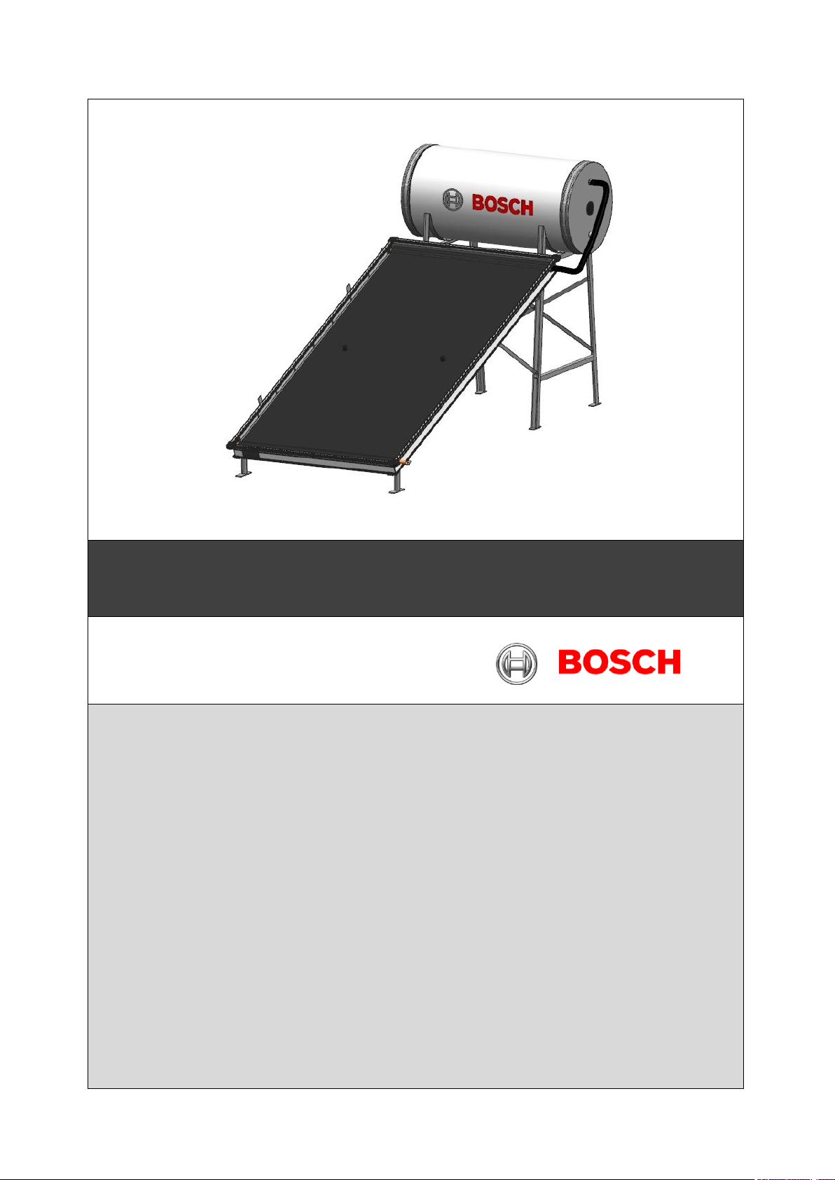
Thermosiphon systems
User manual & installation guidelines
C08002D : Version 2 : 20140910
6 720 803 996
1

Table of contents
1. Key to symbols and safety instructions ----------3
1.1 Key to symbols--------------------------------------------3
1.2 Safety instructions----------------------------------------3
2. Information about the installation set-------------4
2.1 Intended use-----------------------------------------------4
2.2 LIGHTNING PROTECTION----------------------------4
2.3 Important Working Conditions-------------------------4
3. Working Principle-- -------------------------------------5
4. Specifications---------------------------------------------6
5. Before installation --------------------------------------8
5.1 General notes----------------------------------------------8
5.1.1 Instructions to Dealer, Installers
and customers------------------------------------------9
5.2 Required tool & Equipments--------------------------10
5.3 Transport and storage---------------------------------10
5.4 Estimating space requirements---------------------10
6 Installing of Solar Water Heating Systems-----11
6.1 Installation of Flat roof mounting structure for
building not taller than 20m--------------------------11
6.2 Tank Installation ---------------------------------------11
6.2.1 Installation of Tank on flat roof.-------------------11
6.3 Collector Installation------------------------------------11
6.3.1 Installation of Collector on flat roofs--- ----------11
6.4 Positioning for first collector.-------------------------12
6.5 Installation of additional collector for 200/300/500
Lts systems--------------------------------- ------------13
7. Installation of connection Lines------------------14
7.1 Installation of dummy hose pipes-------------------14
7.2 Connecting the cold Water Hose Pipe-------------14
7.3 Connecting the Hot Water Inlet Pipe---------------14
8 Typical Arrangement of Solar Water Heating
System-----------------------------------------------------15
9. Installation& Commissioning of 2-C Systems-16
9.1 Installation of tank and collector --------------------16
9.2 Installation of makeup tank --------------------------16
9.3 Procedure for filling Secondary Circuit in 2-C
Systems--------------------------------------------------------16
9.4 Quantity of DM Water/glycol mixture required for
2-C Systems--------------------------------------------16
9.5 Recommended Properties of Glycol---------------17
9.6 Glycol Health hazard data----------------------------17
9.7 Preventive Measures-----------------------------------17
__________________________________________
10.0 Installation of pressurized Systems---------18
10.1 Installation of Tank and Collector----------------- 18
10.2 Pressurized Hose Pipe Assembly----------------18
10.2.1 Cold Water Pipe ( CWI) Assembly-------------18
10.2.2 Hot Water Pipe Assembly------------------------18
10.2.3 Dummy Connector Assembly--------------------18
11. Commissioning---------------------------------------19
11.1 Securing Mounting Structure with Cement
Concrete--------------------------------------------- -19
12. Important Instructions-----------------------------19
12.1 Instructions to Installers-----------------------------19
12.2 Instructions to Customers-------------------------- 20
12.2.1 System Usage---------------------------------------20
13. Checks after Installation & Commissioning-20
14 Maintenance-------------------------------------------- -20
14.1 Installation of systems-------------------------------20
14.2 Maintenance of Collector----------------------------21
14.3 Maintenance of Tank---------------------------------21
14.4 Procedure for installing Electric Heater----------21
14.4.1 Enamel Tank Systems-----------------------------21
14.4.2 Stainless Tank Systems---------------------------21
14.5 Procedure for removing Sacrificial Anode-------21
15 Trouble Shooting of Solar Thermal Systems-22
16. Environment and disposal-------------------------22
17 Installation and commissioning Certificate---24
18. Warranty Certificate----------------------------------26
2
1 Key to symbols and safety instructions
Warnings in this document are framed
and identified by a warning triangle
which is printed on a grey background.
Electrical hazards are identified by a
lightning symbol surrounded by a
warning triangle.
Important information in cases where
there is no risk of personal injury or
material losses is identified by the
symbol shown on the left. It is
bordered by horizontal lines above
and below the text.
Symbol
Meaning
a step in an action sequence
a reference to a related part in the
document or to other related
documents
•
a list entry
–
a list entry (second level)
1.1 Key to symbols
Warnings
Keywords indicate the seriousness of the hazard in
terms of the consequences of not following the safety
instructions.
• NOTICE indicates that material damage may occur.
• CAUTION indicates that minor to medium injury
may occur.
• WARNING indicates that serious injury may occur.
• DANGER indicates possible risk to life.
Important information
Additional symbols
Table 1
1.2 Safety instructions
This chapter explains how the information in these
installation instructions is laid out, and gives general
safety instructions for safe and trouble-free operation.
Safety instructions and user notes relating specifically
to installation are found in the installation instructions
alongside the specific installation steps. Please read
the safety instructions carefully before starting the
installation. If safety instructions are ignored, severe
or even fatal injuries may result, as well as material
losses and environmental damage.
▶ Always wear personal protective clothing and
safety equipment during entire installation activity.
▶ After completing the installation, check the
mounting set, the collectors and the tank are
securely positioned.
Installation and maintenance
▶ Only have the appliance installed or modified by an
Installer approved by Bosch.
▶ Only use the tank for heating domestic hot water
(DHW).
Risk of scalding
Always monitor operation of the system if
temperatures are above 60 °C.
▶ We recommend installing a DHW mixing valve
downstream of the "DHW outlet" connection to
avoid direct exposure to hot water.
Risk of scalding
If the collector and installation material have been
exposed to the sun's rays for a prolonged period,
touching certain components may cause burns.
▶ Always wear personal protective clothing and
safety equipment during installation & Maintenance.
▶ Before and during installation, cover the collector
with an opaque material to protect against high
temperatures caused by solar radiation. It is
essential to cover the equipment, until the system is
commissioned.
Maintenance
▶ Customer recommendation: Arrange for an
inspection / maintenance contract with Bosch
approved dealer, and have the appliance serviced
at least once in a year. If quality of water is hard,
servicing of the system should be done more
regularly.
▶ The user is responsible for the safety and
environmental compatibility of the appliance.
▶ Only use genuine spare parts procured from Bosch
/ Dealer.
General Instructions
To End customers, Dealers & Installers
▶ Dealers / Installers-Instruct the customer about
the functions and operation of the solar water
heating system.
▶ Inform customers that they must not carry out any
modifications or repairs.
Danger when working on roofs
▶ Take appropriate actions to prevent accidents
during all works on roof.
▶ Take precautions against a possible fall of objects
while working on roof.
3

2 Information about the installation
Observe country-specific standards and
directives when installing and operating
the heating system.
The installation of a solar circuit pump can
be considered in place of the
thermosiphon if, due to static
considerations, the roof is unable to bear
the weight of the tank.
IMPORTANT: We recommend our
customers not use the water from solar
system directly for drinking purpose.
set
2.1 Intended use
The rooftop installation set is designed to hold solar
thermal collectors and their associated tank, which
are installed on flat roofs at an angle of 23°/ 33o/ 40°.
Never damage the structure of the building while
installing the solar thermal system.
Conditions of use
Only fit the installation set on roofs with sufficient load
bearing capacity; if necessary, consult a Civil
Engineer / Architect.
The standard installation set is suitable for an
installation height of not more than 20 m.
Consult Bosch to fit additional profile rails, which are
not part of the standard delivery, in the case of
greater installation heights (up to 50 m or with wind
speeds in excess of 129 km/h) .
Never use the rooftop or flat roof installation sets to fix
any other objects to the roof. They are designed only
to hold the solar collectors and tank securely.
2.2 LIGHTNING PROTECTION
• Check regional regulations as to whether a lightning
protection system is required.
• Lightning protection is normally required for
buildings higher than 20 m,
• Have a qualified electrician to install the lightning
protection.
• If a lightning protection system is installed at the
location, check whether the solar thermal system is
also included.
• Consult a Civil Engineer / Architect for further
information, if necessary on "Recommendations on
Lightening Protection"
2.3 Important Working Conditions
The Solar Water heating system requires minimum
one day to generate the required hot water depending
on the solar radiation.
The system will generate the hot water at an average
temperature of 60oC * under standards conditions.
There will be overnight drop in temperature of 6 to
80C at an ambient temperature of 220C. Drop in
temperature will be more at lower ambient
temperature.
When hot water is drawn from the system, equal
amount of cold water enters the solar tank thereby
reducing the overall temperature of the water inside
the tank.
Standard Conditions
- Solar Radiation should be minimum 5.5kW/m
- Inlet water temperature should be minimum 25
2
/day
o
C
- System should be installed as per instructions in
shadow free area.
- No water is drawn from the system during day time
(08:00 to 18:00).
- Output Temperature measured at the outlet of the
solar tank at 18:00 hrs
- Performance of the solar thermal system depends
mainly on Solar Radiation, Geographical and
Climatic Conditions apart from the components.
The performance may accordingly vary from one
location to other.
4
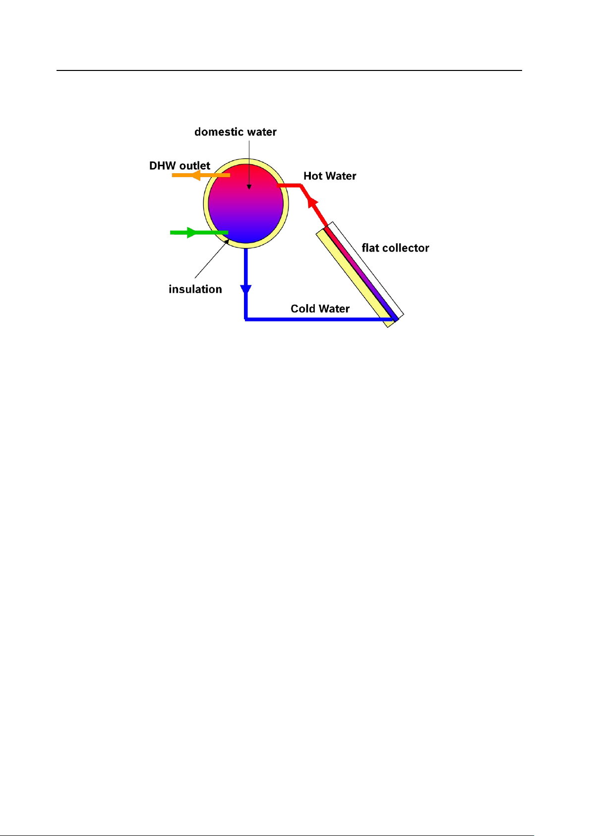
3.0 Working Principle
A typical Solar Water heating system consists of Flat plate collector, Insulated Storage Tank, Mounting structure and
Connection set.
When the sunlight falls on the collector, the heat energy will be absorbed by the absorber. The heat is then
transferred to the water flowing through riser tubes placed beneath the absorber. As the water gets heated it
becomes light and moves upwards towards the insulated solar tank. The void thus created will be filled by the heavy
cold water from the tank. The cycle repeats and this process is called Thermosiphon Process. This process
continues until the temperature of the hot water in the storage tank and the absorber equalizes. Since the tank is
insulated, The hot water stored in the tank will be available for usage next day morning.
5

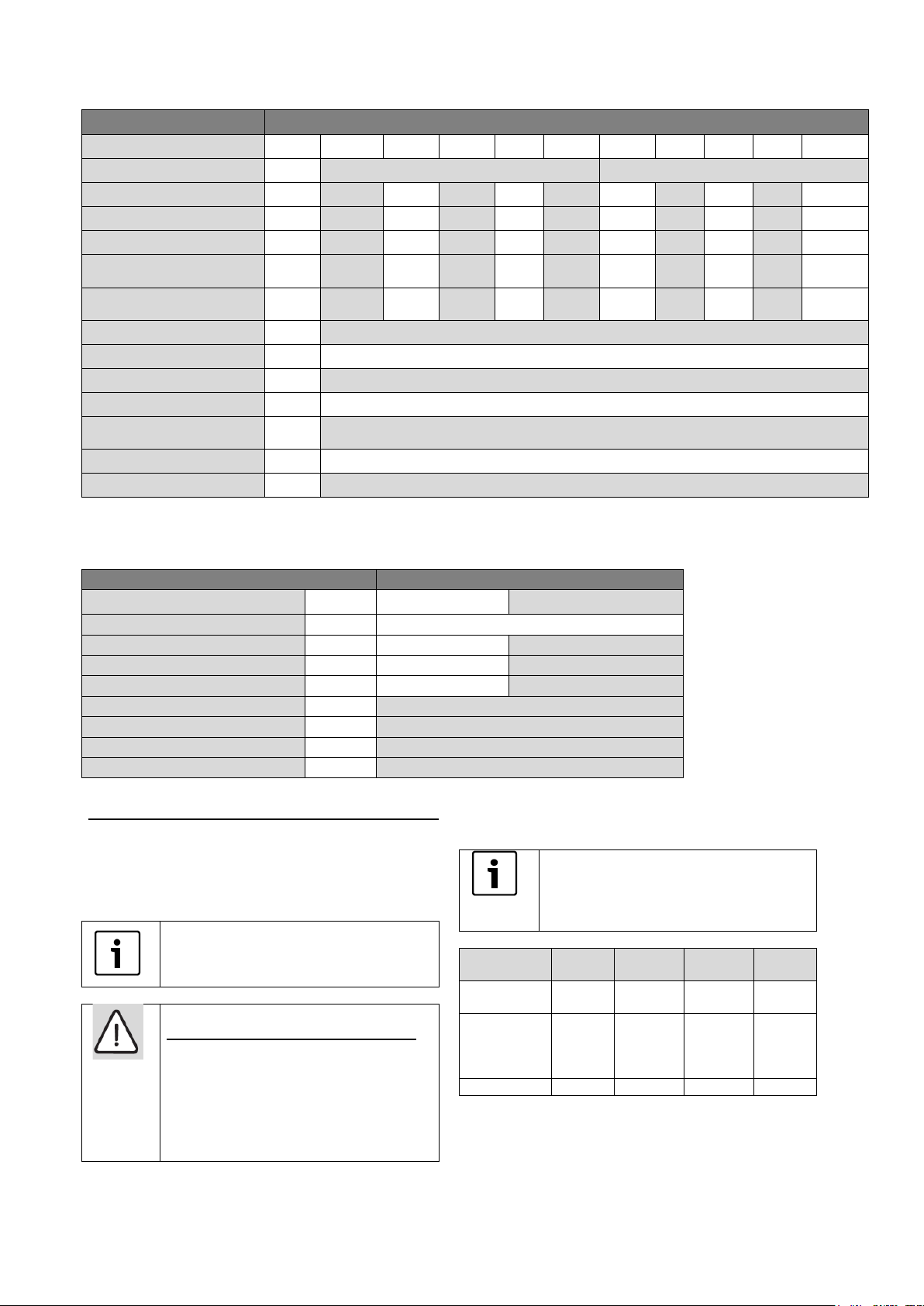
4 Specifications
Collector
Certificate
Certified by Bureau of Indian Standards as per IS
12933 Part I
Model
FCB 120-1V
Overall Dimensions of collector
mm
1032 x 2026 x 92
Weight (empty)
kg
~ 36
Gross area
m2
2.09
Absorber area
m2
1.88
Absorber type
Aluminium Full sheet absorber with black selective
coating and copper harp
Absorber-Harp Bonding
Ultrasonic Welding
Collector Box
Aluminium Extrusion, German Design with Single
piece screw less construction.
Collector Back Sheet
Aluminium Alloy
Back Insulation
Rockwool, 48 kg/m3 density, with thermal resistance
of > 0.96 m2 oC/W
Side Insulation
Polyurethane Foam, 28-32 kg/m3 density, with thermal
resistance of > 0.48 m2 oC/W
Reflective Sheet
Aluminium Foil
Glazing
Textured Solar glass, 3.2 mm thick with transmissivity
of > 91%
Gaskets & Grommets
EPDM rubber
Glass Retainer
Aluminium Extrusion
Max Operating Pressure
kPa
245 ( only for Collectors )
Table 1: Collector specification ( BIS certified )
6
Collector
Model
FCB 120-1V-NB
Length
mm
2026
Width
mm
1032
Weight (empty)
kg
~ 32
Gross area
m2
2.09
Absorber area
m2
1.88
Absorber type
Aluminium Full sheet absorber with black selective
coating and copper harp
Absorber-Harp Bonding
Ultrasonic Welding
Collector Box
Aluminium Extrusion, German Design with Single piece
screw less construction.
Collector Back Sheet
Aluminium Alloy
Back Insulation
Rockwool
Glazing
Textured Solar glass, 3.2 mm thick with transmissivity
of > 91%
Gaskets & Grommets
EPDM rubber
Max Operating Pressure
kPa
345
System
Non Pressurized- Stainless Tank
Storage tank
100L
125L
200L
250L
500L
Type
l
1C
Volume of tank
l
100
125
200
250
500
Diameter
mm
450
480
600
640
900
Length
mm
1150
1190
1140
1190
1230
Approx Weight (empty tank)
kg
18.3
21
26
29
52
Max. operating pressure
KPa
50 (Non pressurized system) (Open vented)
Inner tank
SS 304L
Outer cover
GI pre coated sheet
Insulation
50 mm Polyurethane foam insulation, CFC free
Provision for electrical backup
1 ¼“ BSP Int. thread
Cold water inlet
¾“ BSP External threads
1“BSP
External
Hot water outlet
¾“ BSP External threads
1“BSP
External
Table 2: Collector specification ( Non – BIS)
Table 2: Stainless steel Tank specification
*Note: Due to continuous product development, the product features & specifications, warranty terms and conditions are subject ed
to modifications without notice.
7
System
Pressurized
Storage tank
100L
125L
200L
300L
500L
100L
125L
200L
300L
500L
Type
1C
2C
Volume of tank
l
100
125
200
300
500
100
125
200
300
500
Diameter of tank
mm
500
500
600
600
750
520
520
620
620
750
Length of the Tank
mm
1025
1224
1245
1846
1900
1025
1224
1245
1846
1900
Approx Weight (empty
tank)
kg
42
47
56
80
115
52
60
75
107
145
Approx Weight ( filled with
water)
kg
142
172
256
380
615
152
185
275
407
645
Max. operating pressure
KPa
350
Inner tank Material
Enamel coated Steel
Outer cover
GI pre coated sheet
Insulation
50mm PUF insulation, CFC free
Provision for electrical
backup
1 ¼“ BSP INT thread
Cold water inlet
1” BSP EXT thread
Hot water outlet
1” BSP EXT thread
Table 3: Enamel Tank specification
System
Non Pressurized-Polymer Tank
Storage Capacity
L
125
250
Type
l
1C
Diameter
mm
500
700
Length
mm
970
990
Approx Weight (empty tank)
kg
14
22
Max. operating pressure
KPa
0 ( Integrated with Float Tank)
Inner tank
Food grade LMDPE, 5 mm thick
Outer cover
LMDPE, 3 mm thick
Insulation
Polyurethane Foam, 28-32 kg/m3 density
We recommend that you engage the
services of a roofing contractor who will
be experienced in working on roofs and
aware of avoiding the risk of falling
DANGER: Risk to life through falls and
falling parts!
▶ Take all necessary steps against
possible fall while working on roofs.
▶ Always wear personal protective
clothing and safety equipment.
After completing the installation, check the
installation set, the collectors and the tank
are securely positioned.
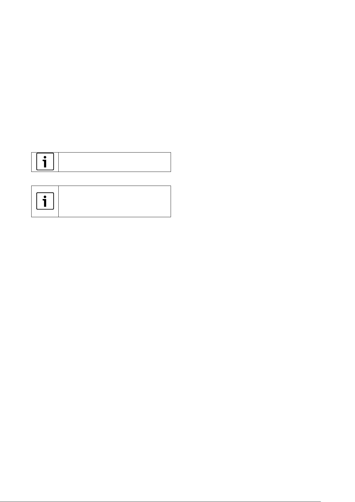
Water Sample: It is mandatory to test the
water sample before choosing the right
system. The below table shows the
recommended solar water heater for
different water quality
Parameter
SS
tank
Polymer
Tank
Enamel
1-C
Ename
l 2-C
Chlorides
(ppm)
< 50
< 600
< 250
< 250
Total
Hardness
(CaCo3)
ppm
< 150
< 300
< 300
< 900
PH
6.5-8.0
6.5-8.0
6.5-8.0
6.5-8.0
Table 6 Water quality
*Note: Due to continuous product development, the product features & specifications, warranty terms and conditions are subjected
to modifications without notice.
5.0 Before installation
Make yourself familiar with the on-site conditions and
local regulations before commencing the installation.
5.1 General notes
8
5.1.1 Instructions to Dealers, Installers &
Only use original spare parts from the
manufacturer and replace faulty parts
immediately.
Have a professional roofer to carry out all
difficult roof repairs, particularly sealing the
roof if there is any seepage of water
through the roof during draining / servicing
of the system
Customers
Check;
Whether the delivered material is complete
and undamaged.
The structure of the roof for sufficient load
bearing capacity and damage.
The optimum arrangement of the solar
collectors. Take solar radiation into account
(southerly orientation). Avoid shade from high
trees or similar structures.
The stability of the installation surface.
Remove gravel or similar material.
9
 Loading...