

Bosch FAP-O 500, FAP-O 500-P, FAP−OC 500, FAP-OC 500-P Product Information
PRODUCT INFORMATION PI−34.70 en
A5.en / 02.02.2006
Page 0
ST−FIR/PRM1 / zab
BDL−F.01U.025.876
500 Series
LSN Fire Detectors (EU)
FAP−O 500 / FAP−O 500−P
FAP−OC 500 / FAP−OC 500−P
with FAA−500 Components


PI − 34.70 enProduct Information 500 Series LSN Fire Detectors (EU)
Page 3
BDL−F.01U.025.876
A5.en/ 02.02.2006
ST−FIR/PRM1 / zab
Table of Contents
1. Product Description 5. . . . . . . . . . . . . . . . . . . . . . . . . . . . . . .
1.1. System Description 7. . . . . . . . . . . . . . . . . . . . . . . . . . . . . . . . . . . . . . . . . .
1.2. Configuration of the Detector 7. . . . . . . . . . . . . . . . . . . . . . . . . . . . . . . . .
1.3. Functional Description of the Sensor Technology 8. . . . . . . . . . . . . . . .
1.4. LED Operation 9. . . . . . . . . . . . . . . . . . . . . . . . . . . . . . . . . . . . . . . . . . . . . .
1.5. Performance Features 10. . . . . . . . . . . . . . . . . . . . . . . . . . . . . . . . . . . . . . .
2. Planning Notes 11. . . . . . . . . . . . . . . . . . . . . . . . . . . . . . . . . . .
3. Programming 12. . . . . . . . . . . . . . . . . . . . . . . . . . . . . . . . . . . . .
4. Technical Specifications 14. . . . . . . . . . . . . . . . . . . . . . . . . . .
4.1. Detector and Trim Ring 14. . . . . . . . . . . . . . . . . . . . . . . . . . . . . . . . . . . . . .
4.2. Detector Base 15. . . . . . . . . . . . . . . . . . . . . . . . . . . . . . . . . . . . . . . . . . . . . .
4.3. Mounting Boxes 16. . . . . . . . . . . . . . . . . . . . . . . . . . . . . . . . . . . . . . . . . . . .
5. Mounting Notes 17. . . . . . . . . . . . . . . . . . . . . . . . . . . . . . . . . . .
5.1. Ceiling Mount Back Box 17. . . . . . . . . . . . . . . . . . . . . . . . . . . . . . . . . . . . . .
5.2. Detector Base / Detector Base with Relay 19. . . . . . . . . . . . . . . . . . . . . .
5.3. Detector and Trim Ring 22. . . . . . . . . . . . . . . . . . . . . . . . . . . . . . . . . . . . . .
5.4. Built−in Housing for Concrete Ceilings 23. . . . . . . . . . . . . . . . . . . . . . . . .
5.5. Surface Mount Back Box 24. . . . . . . . . . . . . . . . . . . . . . . . . . . . . . . . . . . . .
5.6. External Detector Alarm Displays 26. . . . . . . . . . . . . . . . . . . . . . . . . . . . .

PI − 34.70 enProduct Information 500 Series LSN Fire Detectors (EU)
Page 4
BDL−F.01U.025.876
A5.en/ 02.02.2006
ST−FIR/PRM1 / zab
6. Order Overview 30. . . . . . . . . . . . . . . . . . . . . . . . . . . . . . . . . . .
6.1. Detectors and Trim Ring 30. . . . . . . . . . . . . . . . . . . . . . . . . . . . . . . . . . . . .
6.2. Detector Bases / Accessories 31. . . . . . . . . . . . . . . . . . . . . . . . . . . . . . . . .
6.3. Mounting Boxes 31. . . . . . . . . . . . . . . . . . . . . . . . . . . . . . . . . . . . . . . . . . . .
6.4. Service Tools / Accessories 31. . . . . . . . . . . . . . . . . . . . . . . . . . . . . . . . . .
7. Maintenance and Service 32. . . . . . . . . . . . . . . . . . . . . . . . . .
7.1. Notes for the Service 33. . . . . . . . . . . . . . . . . . . . . . . . . . . . . . . . . . . . . . . .
7.2. General Notes for Detector Testing 34. . . . . . . . . . . . . . . . . . . . . . . . . . . .
7.3. Inspection Procedure for FAP−OC 500 35. . . . . . . . . . . . . . . . . . . . . . . . .
7.4. Inspection Procedure for FAP−O 500 37. . . . . . . . . . . . . . . . . . . . . . . . . .
8. Repair 38. . . . . . . . . . . . . . . . . . . . . . . . . . . . . . . . . . . . . . . . . . .
9. Disposal 38. . . . . . . . . . . . . . . . . . . . . . . . . . . . . . . . . . . . . . . . .
10. Additional Documentation 38. . . . . . . . . . . . . . . . . . . . . . . . .
11. Abbreviations 39. . . . . . . . . . . . . . . . . . . . . . . . . . . . . . . . . . . .

PI − 34.70 enProduct Information 500 Series LSN Fire Detectors (EU)
Page 5
BDL−F.01U.025.876
A5.en/ 02.02.2006
ST−FIR/PRM1 / zab
«
1. Product Description
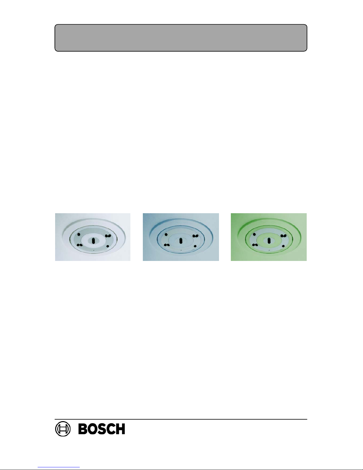
With their low profile design, flush−mounted installation and possibilities for color toning, the fire detectors in the 500 series open up a new dimension with respect to aesthetic and functional demands.
The cooperation of engineers and designers has created the timeless, innovative design of this detector, which integrates pleasantly into the ceiling. The detectors with
associated trim ring are available in the versions «white» and «transparent with color
toning inserts». Through the use of the supplied color toning inserts, optimum adjustment to many different environments becomes possible.
The lack of an optical labyrinth and their easily−cleaned smooth surface means the
detectors are also suitable for applications in high−dust areas.
The low profile, flush−mounted design allows the use of the detectors even in areas
that must be free of protrusions.
Thanks to the geometric arrangement of two separate optical sensor systems, the detectors are not sensitive to interference, such as that caused by insects. The scattered
light volume that is evaluated by the sensors is located in the free space a few centimeters below the ceiling.
The contamination level is measured constantly. Contamination of the detector surface leads to an active adjustment of the threshold (drift compensation) and a fault indication at the panel in the case of heavier contamination.
The detector is available as a scattered light fire detector only or as a multisensor detector with an additional gas sensor.
The combination of scattered light detector and gas sensor allows the evaluation of
signals with the help of modern signal processing methods. The result is high immunity
against deceptive alarms and extended application possibilities in environments that
are not suitable for pure scattered light smoke detectors.
The FAP−500 detectors can be connected directly to the Local SecurityNetwork LSN.
Accessories
The detectors are generally mounted flush with the ceiling in false ceilings. The detector and base are installed in a robust ceiling mount back box. In addition, a housing
for mounting within concrete ceilings can be used.
For special applications where recessed ceiling mounting is not possible, a surface
mount back box is available. This is used as an alternative to the ceiling mount back box.
The surface mount back box with damp room seal also allows the detector to be used
in a humid environment.
For special applications, e.g. control of an emergency door in accordance with DIBt,
base variants are available with relay (only in combination with the Modular Fire Panel
FPA−5000).

PI − 34.70 enProduct Information 500 Series LSN Fire Detectors (EU)
Page 6
BDL−F.01U.025.876
A5.en/ 02.02.2006
ST−FIR/PRM1 / zab
In the GB−base versions, integrated jumper elements are provided that preserve the
loop function if the detector is removed.
All bases have an integrated strain relief for false ceiling cables.
The connection terminals are easily accessible. Cables up to 3.3 mm2 in cross section
can be used.
An innovative concept for locking the detector module utilizing the push−in/push−out prin-
ciple allows very quick and easy insertion and exchange of the click and lock detector.
For the detector test and detector exchange, a special user−friendly service accessory
is available.
Overview of the 500 series LSN detectors and accessories
LSN detectors
D FAP−O 500 Optical fire detector LSN, white
D FAP−O 500 P Optical fire detector LSN,
transparent with color toning inserts
D FAP−OC 500 Multisensor fire detector LSN, optical/chemical, white
D FAP−O 500−P Multisensor fire detector LSN, optical / chemical,
transparent with color toning inserts
D FAA−500−TR−W White trim ring for detectors series 500 and 520
D FAA−500−TR−P Transparent trim ring with color toning inserts for detectors
series 500 and 520
LSN detector bases
D FAA−500 LSN detector base
D FAA−500−R LSN detector base with relay*
D FAA−500−GB LSN detector base for Great Britain
D FAA−500−R−GB LSN detector base for Great Britain with relay*
D FAA−500−SPRING Spring for concrete and wooden ceiling
* for connection to the Modular Fire Panel FPA−5000 only
Mounting boxes
D FAA−500−BB Ceiling mount back box
D FAA−500−CB Built−in housing for concrete ceilings
D FAA−500−SB Surface mount back box
D FAA−500−SB−H Surface mount back box with damp room seal
Service Accessories
D FAA−500−RTL Detector exchanger for 500 and 520 series detectors
D FAA−500−TTL Test adapter with magnet for 500 and 520 series detectors
PI − 34.70 enProduct Information 500 Series LSN Fire Detectors (EU)
Page 7
BDL−F.01U.025.876
A5.en/ 02.02.2006
ST−FIR/PRM1 / zab
1.1. System Description
All detectors in the 500 series are equipped with two optical sensors and a pollution
sensor. The FAP−OC 500 multisensor detector contains a gas sensor as an additional
detection channel.
The response sensitivity of the detector can be programmed with the programming
software via the LSN network. All sensor signals are analyzed continually by the internal signal evaluation processor and are linked with each other.
By linking the optical sensors and the gas sensor, the OC detector can also be used
in places where the work carried out gives rise to small amounts of smoke, steam or
dust. The alarm will only be triggered automatically if the signal combination corresponds with the characteristic diagram of the installation location that was selected
during configuring.
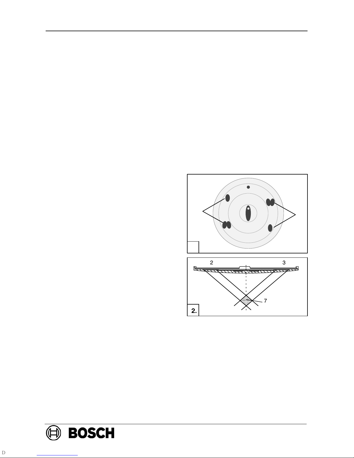
1.2. Configuration of the Detector
Fig. 1.: Detector front panel with sensors
Fig. 2.: Side view of detector cover
1 = Optical sensor
2 = Receiver (photo diodes)
3 = Transmitter (LEDs)
4 = CO sensor
5=Two−color LED:
red = alarm
green = test mode / trouble
6 = Pollution sensor
7 = Measuring area
1
1
2
3
3
2
4
5
6
1.
23
7
2.

PI − 34.70 enProduct Information 500 Series LSN Fire Detectors (EU)
Page 8
BDL−F.01U.025.876
A5.en/ 02.02.2006
ST−FIR/PRM1 / zab
1.3. Functional Description of the Sensor Technology
Optical sensor (smoke sensor)
The optical sensor (Fig. 1., Pos. 1) operates according to the scattered light principle.
The LEDs (Fig. 1., Pos. 3) transmit light at a defined angle into the measuring area
(Fig. 2., Pos. 7). In case of fire, the light is scattered by the smoke particles and strikes
the photo diodes (Fig. 1., Pos. 2), which transform the quantity of light into a proportional electrical signal.
The effects of daylight and commercial lighting sources are filtered out with an optical
daylight filter and by the use of electronic filtering and phase−locked rectification (ambient light stability: glare test DIN EN 54−7).
The various light−emitting and photo diodes of the detector are individually activated.
Consequently, signal combinations are produced that are independent of each other
and ideally suitable for the detection of smoke, which makes it possible to differentiate
between smoke and interference agents (insects, objects). In addition, the time characteristics and the correlation of the optical sensor signals for the fire or interference
detection are evaluated.
Moreover, plausibility checking of the various signals makes it possible to detect errors
in the evaluation electronics and the LEDs.
Chemical sensor (CO gas sensor)
The gas sensor (Fig. 1., Pos. 4) detects mainly the carbon monoxide (CO) that is produced by a fire, but it also detects hydrogen (H) and nitrogen monoxide (NO).
The basic measuring principle is CO oxidation on an electrode and the measurable current
that arises from this. The sensor signal value is proportional to the concentration of gas.
The gas sensor supplies additional information in order to reliably suppress the disturbance variables.
The CO sensor is monitored by supervision of the internal capacity. If the capacity lies
outside the permitted range, a malfunction signal is output on the fire panel. In this
case, the detector continues to operate purely as a scattered light smoke detector.
Pollution sensor
The contamination level of the detector surface is measured and evaluated continuously by the pollution sensor (Fig. 1., Pos. 6). A three−stage contamination display can
be read out at service (see Chapter 7.1.).

PI − 34.70 enProduct Information 500 Series LSN Fire Detectors (EU)
Page 9
BDL−F.01U.025.876
A5.en/ 02.02.2006
ST−FIR/PRM1 / zab
1.4. LED Operation
The two−color LED of the detector indicates the operation and alarm statuses.
During the whole life cycle, the sensors are self−monitored and the sensitivity is self−
adjusted according to the programmed threshold. In case the detector is heavily contaminated, a message is sent to the fire panel.
In case of an alarm, the LED flashes red. The detector is set back to standby if the
alarm is reset via the fire panel and if the cause of the alarm is gone.
LED Operation
Status LED
Standby off
Alarm red, flashes
Trouble green, double flash every 8 to12 second
Test mode green, flashes once every second

PI − 34.70 enProduct Information 500 Series LSN Fire Detectors (EU)
Page 10
BDL−F.01U.025.876
A5.en/ 02.02.2006
ST−FIR/PRM1 / zab
1.5. Performance Features
D Fulfills the highest aesthetic demands through the flush−mounting design and the
possibility of color toning
D Smooth, easily−cleaned detector surface
D Quick and easy insertion and exchange of the detector thanks to innovative
detector locking mechanism (click and lock principle).
D Easily−visible two−color LED for display of alarm, trouble and test mode
D Self−monitoring of the sensors, with display on the fire panel:
− Fault indication upon failure of the evaluation electronics or one of the LEDs of
the optical sensor
− Three−stage contamination display (analog value can be read out at service)
− Fault indication in the case of heavy contamination (instead of false alarm)
− Fault indication in the case of CO sensor failure (for the FAP−OC 500)
D Thanks to integrated isolators, the LSN loop will continue to function in case of wire
interruption or short−circuit of a detector
D Active adjustment of the threshold (drift compensation) if the optical sensor be-
comes contaminated
D Active adjustment of the threshold (drift compensation) of the chemical sensor
D Increased detection and false alarm immunity thanks to evaluation of the time
behavior of fire and disturbance variables
D Programmable sensitivity, i.e. can be adjusted to the area of operation
D Detector individual identification on the fire panel in the case of alarm
D A pre−alarm is signaled when 50% of alarm threshold is reached (indicator in the
event database of the fire panel).
D The serial number, contamination level, operating hours and current analog values
can be read out from each configured detector.
D Activation of an external detector alarm display is possible (not for relay bases)
D Activation of external devices with relay base is possible (only in combination with
the Modular Fire Panel FPA−5000)
D Easily−accessible connection terminals
D Service accessories for simple and comfortable detector test and exchange
D When using the FAA−500−TTL test adapter, an integrated reed switch automati-
cally switches the detector into the test mode.
D The EMC security fulfills the guidelines according to VdS 2110 (VdS Schaden-
verhütung GmbH) as well as UL 268.
D Can be connected to the LSN fire panels FPA−5000, BZ 500 LSN, UEZ 2000 LSN,
UGM 2020 and to other fire panels or their receiver modules with identical connection conditions.
D VdS Approval
D CE conform according to EN 54−7
PI − 34.70 enProduct Information 500 Series LSN Fire Detectors (EU)
Page 11
BDL−F.01U.025.876
A5.en/ 02.02.2006
ST−FIR/PRM1 / zab
2. Planning Notes
The 500 series detectors are approved for indoor use only!
The detectors must be installed exclusively in the FAA−500 bases
provided. In addition, the detector base must be installed in an
FAA−500−BB ceiling mount back box or in an FAA−500−SB surface
mount back box.
D Country−specific standards and guidelines must be observed during the planning
phase.
D The FAP−OC 500, like the FAP−O 500, is planned according to the guidelines for
optical detectors; see DIN VDE 0833 Part 2 and VdS 2095.
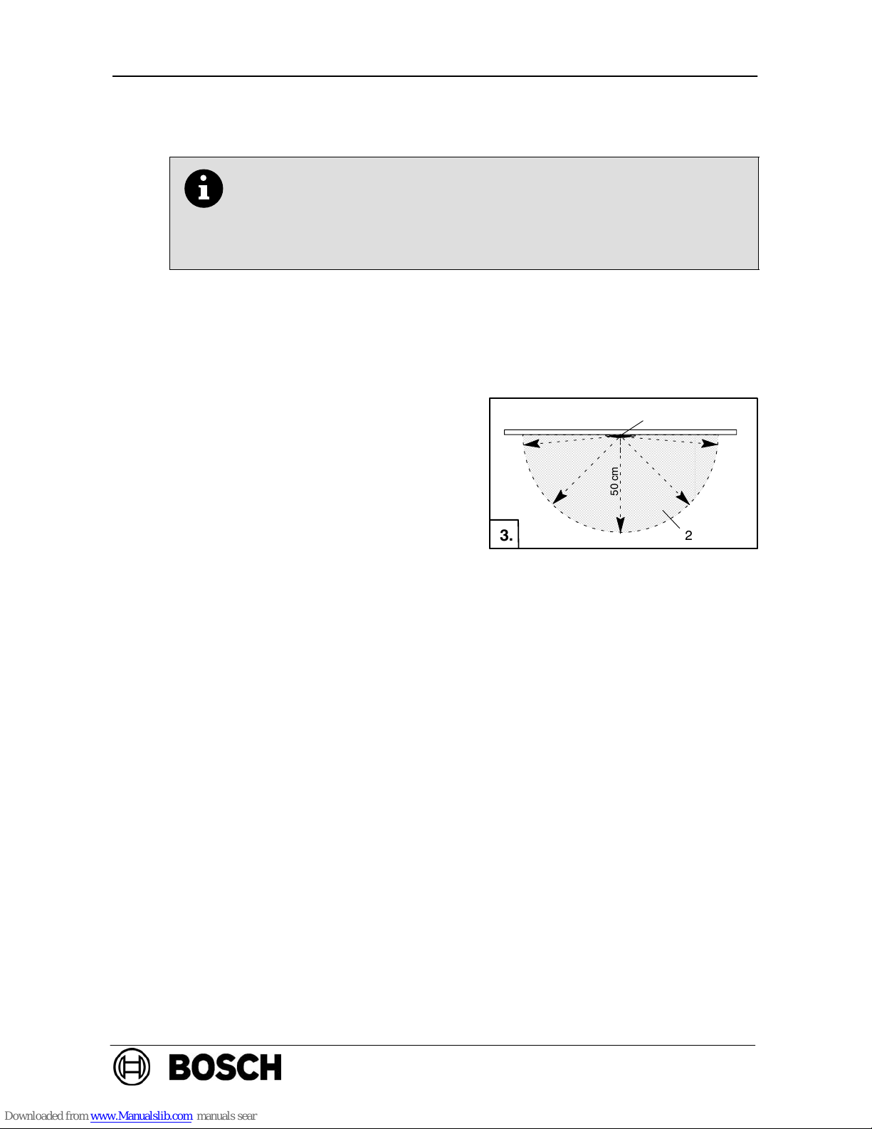
D A hemispherical space (see Fig. 3., Pos. 2)
with a radius of 50 cm must remain free
below the detector (Pos. 1).
Care must be taken to ensure that no people, larger animals, plants, opening doors
or any objects intrude into this area and
that no parts of the detector surface become covered.
D The detector may only be installed in a position which is out of arm’s reach.
Minimum installation height recommended by BOSCH: 2.70 m.
D The 500 series detectors may not be installed in rooms with data transmission by
means of high−intensity infra−red light (e.g. in rooms with IR systems for interpreters).
D The detectors must be mounted so that they are not exposed to any direct sunlight.
D A minimum distance of 50 cm from lamps must be maintained.
The detectors may not be mounted in a cone of light from lamps.
D The standard spring inside the bases allows detector mounting in false ceiling
panels. For concrete and wooden ceiling, replace with the FAA−500−SPRING with
red marking (ordering information see section 6.2.).
D Maximum permitted air speed: 20 m/s.
D Maximum number of FAP−500 detectors connectable to the Local SecurityNetwork
LSN:
− BOSCH LSN fire panels: up to 28 detectors per NVU as loop or stub line
− Modular Fire Panel FPA−5000: up to 85 detectors per LSN 0300−Modul.
1
50 cm
2
3.

PI − 34.70 enProduct Information 500 Series LSN Fire Detectors (EU)
Page 12
BDL−F.01U.025.876
A5.en/ 02.02.2006
ST−FIR/PRM1 / zab
3. Programming
LSN detectors are programmed according to the required operating mode.
Programming is carried out with the programming software using a PC or laptop con-
nected to the fire panel.
The suitable response sensitivity of the multisensor detector is programmed by speci-
fying the operating location (e.g. computer room, office, large kitchen). The selection of
the operation location determines the optimal characteristic diagram for the fire and disturbance variable evaluation.
If, according to the operating location, a low sensitivity is set for the optical sensor, the
alarm goes off only if the detector senses high levels of smoke and of CO at the same
time. This is the case with open or smouldering fire.
Programming the multisensor detector and linking all detectors by algorithms, considerably increases the fire detection reliability and lowers the false alarm rate.
FAP−OC 500(−P)
Operating locations for multisensor detector
Sensitivity
Operating locations for multisensor detector
(FAP−OC 500) selectable via the programming software
O unit C unit
Office (smokers) / waiting room / restaurant / conference
room
low
g
Conference room / waiting room / exhibition hall low
s
atin
Warehouse with vehicle traffic low
wa
y
per
a
Production facilities low
s al
w
e o
Kitchen / casino / restaurant during operation low
nit i
s
f t
h
Garage low
C u
n
ss
o
Office (daily operation) medium
he
C
rdle
s
School / kindergarten medium
of t
h
ga
r
Theaters / concert halls medium
ity
o
, r
e
Office (no traffic) high
siti
v
hig
h
.
Computer room high
sen
lly
h
ion.
High−board warehouse without vehicle traffic with internal
combustion engines
high
The sequalocat
 Loading...