

Bosch EX85 Installation Instructions Manual
INSTALLATION INSTRUCTIONS
EX85
MEGAPIXEL-IP INFRARED IMAGER™
MAN – 85 – 02

IMPORTANT SAFETY INSTRUCTIONS
1. Read these instructions.
2. Keep this instruction.
3. Heed all warnings.
4. Follow all instructions.
5. Do not use this apparatus near water.
6. Clean only with dry cloth.
7. Do not block any ventilation openings. Install in
accordance with manufacturer instructions.
8. Do not install near any heat sources such as radiators,
heat registers, stoves or other apparatus (including
amplifiers) that produce heat.
9. Do not defeat the safety purpose of the polarized or
grounding-type plug. A polarized plug has two blades
with one wider than the other. A grounding type plug
has two blades and a third grounding prong. The wide
blade or the third prong is provided for your safety. If
the provided plug does not fit into your outlet, consult
an electrician for replacement of the obsolete outlet.
10. Protect the power cord from being walked on or
pinched particularly at plugs, convenience receptacles,
and the power where they exit from the apparatus.

11. Only use attachments/accessories specified by the
manufacturer.
12. Use only with the cart, stand, tripod, bracket, or table
specified by the manufacturer, or sold with the
apparatus. When a cart is used, use caution when
moving the cart/apparatus combination to avoid injury
from tip-over.
13. Unplug this apparatus during lightning storms or when
unused for long periods of time.
14. Refer all servicing to qualified service personnel.
Servicing is required when the apparatus has been
damaged in a way, such as power-supply cord or plug
is damaged, liquid has been spilled or objects have
fallen into the apparatus, the apparatus has been
exposed to rain or moisture, does not operate normally,
or has been dropped.
IMPORTANT
For best results, please read this Instruction Booklet prior
to installing the EX85 Megapixel-IP Infrared Imager™
WARNING!
CSA Certified / UL Listed CLASS 2 power adaptors must
be used in order to comply with electrical safety
standards.
This installation should be made by a qualified service
person and conform to all local safety codes.
Bosch Security Systems Inc. will not be responsible for
injuries or damages resulting from the improp er
installation or use of any equipment sold by Bosch
Security Systems Inc., their agents, distributors or
dealers.

NOTE: This equipment has been tested and found to
comply with the limits for a digital device, pursuant to part
15 of the FCC rules. These limits are designed to provide
reasonable protection against harmful interference in a
residential installation. As part of it's normal operation this
device can generate radio frequency ener gy and if not
installed and used in accordance with the installation
manual may cause interference to radio communications.
However, there is no guarantee that interference will not
occur on a particular installation. If the device does cause
interference to radio or television reception the user is
encouraged to try to correct the interference by one or
more of the following measures:
1) Fit Ferrite beads on all cable to and from the power
supply box, within the box walls.
2) Route the composite cable between the camera and the
power supply in steel conduit piping over the entire run of
the cable up to and including connectio n to a deep conduit
base fitted under the camera and a conduit fitting adaptor in
the wall of the PSU box.
3) Contact BOSCH Service Center for further advice.

INDEX – EX85 Megapixel-IP Infrared Imager™
DESCRIPTION...........................................................................1
UNPACKING..............................................................................2
PARTS LIST...............................................................................2
ITEMS REQUIRED FOR INSTALLATION.................................2
NETWORK SYSTEM REQUIREMENTS...................................3
INITIAL PREPARATIONS..........................................................4
GUIDELINES .............................................................................4
1. MOUNTING BRACKET PREPARATON ...................5
2. CABLE / BRACKET INSERTION...............................6
3. MOUNTING BRACKET ATTACHMENT....................7
4. CAMERA MOUNTING ..............................................8
5. CAMERA LENS ADJUSTMENTS............................11
6. LED ARRAY - POWER ADJUSTMENTS................14
7. VIEWING SOFTWARE SET-UP..............................15
8. APPLICATION MANAGER PROGRAM ..................17
9. CAMERA INSTALLER.............................................18
10. VIDEO SYSTEM......................................................21
11. SETTINGS...............................................................25
12. IMPORTANT CAMERA SETTINGS ........................39
13. CAMERA RE-ASSEMBLY.......................................40
14. TROUBLESHOOTING GUIDE - CAMERA..............41
15. TROUBLESHOOTING GUIDE – LEDs....................43
16. MOUNTING HOLES – DIAGRAM ...........................44
17. GENERAL SPECIFICATIONS.................................45

DESCRIPTION
The EX85 is the pinnacle of today’s most advanced
imaging technologies, combining megapixel sensors,
Black Diamond™ night vision technolo gy and IP
connectivity.
The result is the most advanced level of imaging
performance for today’s critical security applications.
Crystal clear megapixel color b y da y delivers images with
amazing details. 420ft (130m) of award-winning Black
Diamond™ megapixel monochrome pr ovides the
industry’s best IP night vision.
The EX85 incorporates the ruggedized enclosure, fieldproven for reliability in the worst outdoor environments.
- 1 -

UNPACKING
Care should be taken when unpacking the shipped unit.
Check the parts list and confirm all items have been
located. Inspect the equipment thoroughly to ensur e
nothing was damaged in transit.
Contact BOSCH Service Center if a problem is noted,
see the rear page of this booklet for contact numbers.
PARTS LIST (items supplied with unit)
- EX85 Camera Assembly
- Installation Instructions booklet
- Allen Key
- EXMB028B or EXMB028W cable manag ement
mounting bracket.
- EX85 Set-Up Software CD
ITEMS REQUIRED FOR INSTALLATION
(not supplied with units)
• Mounting hardware
• Mounting tools
• Computer with RJ45 Ethernet port
• Network switcher (standard or POE type)
• CAT5 Ethernet cable
- 2 -

NETWORK SYSTEM REQUIREMENTS
A dedicated PC is recommended for receiving image
streams from cameras and for archiving and display.
Minimum recommended requirements for the PC are as
follows:
• CPU: Core 2 Duo 2Ghz
• RAM: 1GB
• Video Card: NVIDIA, 128MB RAM
• Network Card: 100 base-T (one card required for
camera stream, a second card required for
remote viewing)
A 100Mbps or better network switch or router is required
to connect the camera to the network. A regular hub does
not provide collision management and is not suitable for
multi-camera systems. Category 5 cabling or better is
recommended, and must be installed according to al l
applicable codes and regulations.
The camera is capable of accepting a standard network
connection. However, the camera unit will still requir e a
dedicated 12-24V power input.
The cameras can be accessed and controlle d by two main
methods: through the included viewing software and
through HTTP commands from a web browser, such as
Internet Explorer.
- 3 -

INITIAL PREPARATIONS
• Determine the operating voltage at the
installation site. The camera‘s Voltage Regulator
Board accepts 12-24V AC/DC input without
change to internal connections.
• Determine the optimum mounting location for the
camera. See Section 4, Camera Mounting.
• All cameras have been tested and pre-focus ed
with telephoto setting as factory default prior to
shipment. If any adjustment needed, it is
advisable to check the camera’s operation before
installation.
GUIDELINES
The installation of the EX85 is sho wn in Sections 1 to 13.
It is important that these steps are followed in numerical
order.
It is also important to follow proper safet y guidelines when
installing this product.
- 4 -
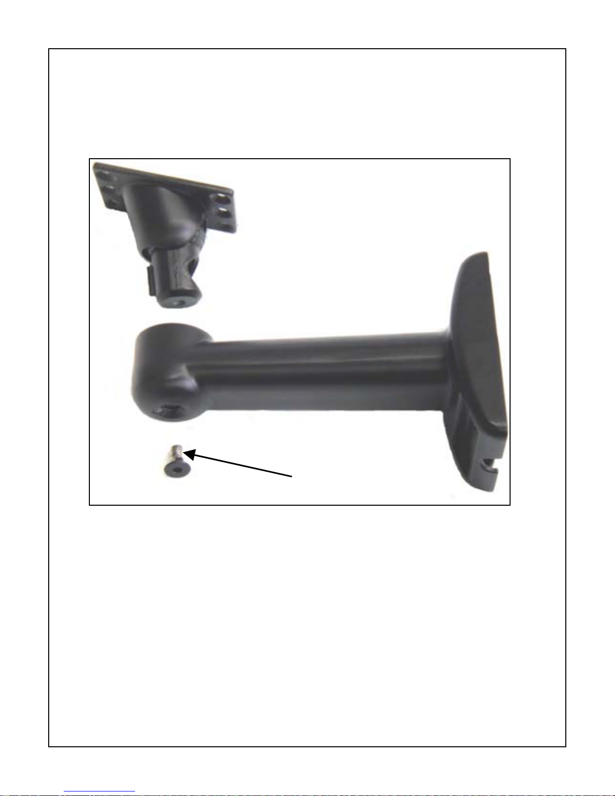
1. MOUNTING BRACKET PREPARATON
EXMB.028 (B or W)
Mounting Bracket
SET SCREW
• Use the supplied Allen Key to remove the
• Separate the two sections of the mounting
setscrew from the supplied mounting
bracket.
bracket.
- 5 -
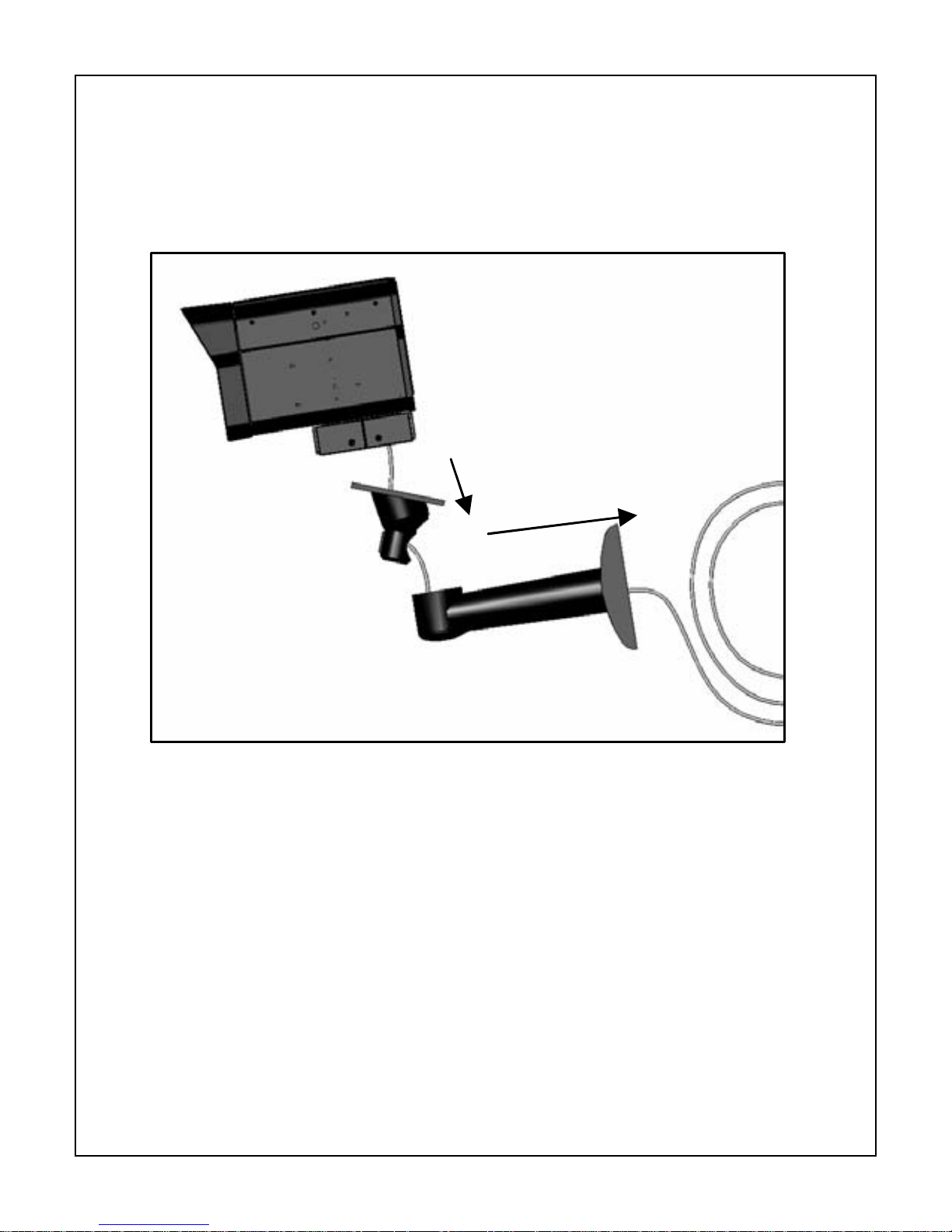
2. CABLE / BRACKET INSERTION
EX85 Camera
• Carefully feed the Power and Ethernet
cables through both sections of the
mounting bracket.
• Make sure the cables are not kinked,
chafed, or split during this procedure.
- 6 -
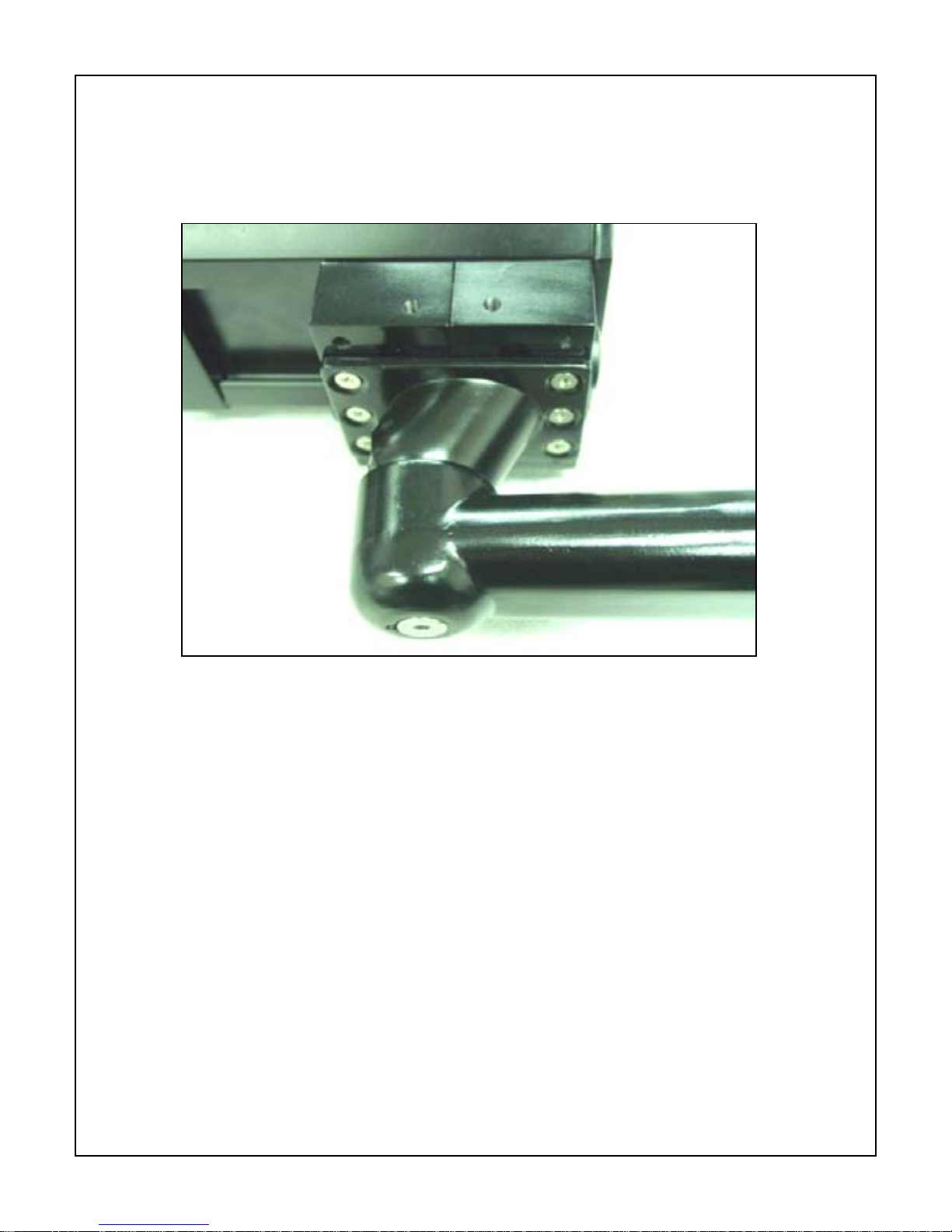
3. MOUNTING BRACKET ATTACHMENT
• Attach the Mounting Bracket to the Camera’s
Mounting Block using the six bolts supplied
with the bracket.
• Snug the two halves of the bracket together
with the Allen head set screw.
• Tighten the setscrew enough so that the
camera can be adjusted for angle. Do not
over-tighten.
• Note the angled part of the mounting bracket
faces to the rear of the camera.
- 7 -

4. CAMERA MOUNTING
Warning: this apparatus must be se curely attached
to the wall or ceiling in accordance with installation
instructions. Failure to follow installation instructions
ma results in injury/death.
Select a suitable location that protects the camera from
accidental damage, tampering and environmental
conditions exceeding the specif ications of the camera to
be mounted.
Caution: Ensure the selected location is protected from
falling objects, accidental contact w ith moving objects and
unintentional interference from personnel. F ollow all
applicable building cod es.
The following installation guidelines must be
followed:
• Locate the bracket such that it cannot be
easily interfered with, either intentionally or
accidentally.
• Select a smooth, flat mounting surface
to
ensure proper sealing. The surface must also be
capable of supporting the combined weight of the
camera and mounting hardware under all
expected conditions of vibration and temperature.
• Secure all cabling.
• Installation should only be performed by
skilled personnel
- 8 -

Hardware required:
• For ceiling mount:
1. Mounting Bracket, Model EXMB.029,
Qty = 1
2. ¼’’ x 2” Lag Screws, Qty = 1
3. ¼’’ Washer, Qty = 1
• For wall mount:
1. Mounting Bracket, Model EXMB.028,
Qty = 1
2. ¼’’ x 2” Lag Screws, Qty = 4
Tools required:
• Drill
• Stud Finder
• 5/32” Drill Bit
• Socket Driver
• 7/16” Socket
Mounting instructions for wall and ceiling mount:
Camera is intended to be securely mounted to a wall
using mounting bracket model EXMB.028, or to a
ceiling using mounting bracket model EXMB.029.
Camera has been evaluated for wall mounting using
the following wood screws secured into a 2x4 stud
under ½” drywall. Wood screws, 1/4” lag, dia Ø1/4”, 2”
long, 9 TPI, with ½” head. Camera has been
evaluated for ceiling mounting using the following
wood screws secured into a 2x4 stud under ½” drywall:
- 9 -

• wood screws with washer, 1/4” lag, dia Ø1/4”,
2” long, 9 TPI, with ½” head
• 16” flat washer.
Camera has not been evaluated for safety
requirements using other mounting kits.
Installation (Ceiling and Wall Mount)
• Locate stud in the ceiling/wall and mark
outside edges of stud.
• Using ceiling/wall mount bracket as a
template, align the mounting hole with the center
of the stud.
• Marking the point on the ceiling/wall in the
center of the hole where mounting screw will be
positioned.
• Remove the ceiling/wall mount bracket and
using a 5/32” drill bit, drill a pilot hole at the
marked point.
• Align the ceiling/wall mount bracket mounting
hole with the hole drilled in the ceiling/wall
• Using a 7/16” socket and driver, secure the
ceiling/wall mount bracket by scre wing the 1/4” la g
bolt with 1/4” washer securely into the stud.
• Use additional 1/4” lag bolt an d 1/4” washer to
secure the remaining mounting holes.
Installation is complete
- 10 -
 Loading...