

Bosch EX72C7V0922-N, EX72MNX8V0922-N, EX72MX4V0922-N Installation Instructions Manual
S
INSTALLATION INSTRUCTION
Precision Engineered Opto-Electronics™
EX72
Explosion Protected Camera
Please read this Instruction Booklet prior to installing the
EX70 and EX70N Explosion Protected Camera.
ATEX Approved or CSA Certified / UL Listed CLASS 2 power
adaptors must be used in order to comply with electrical safety
Only qualified personnel shall install any Bosch Security Systems,
Inc. surveillance product. Bosch Security Systems, Inc. will not be
responsible for injuries or damages resulting from the improper
installation or use of any product sold by Bosch Security Systems,
Inc., their agents,distributors, or dealers
IMPORTANT
WARNING !
standards.
Class 2 circuits shall be supplied from a Class 2 transformer, or
a) A Class 2 power supply or device or
b) Where the voltage does not exceed 20 volts, a 5 ampere
EU Directives covered by this declaration:
72/9/EC Low Voltage Directives
89/336/EEC Electromagnetic Compatibility Directive
94/9/EC Equipment or Protective System for use in
Potentially Explosive Atmospheres.
(maximum) mini circuit breaker or a 5 ampere noninterchangeable fuse.
Certifications / Compliance:
CSA-NRTL: MC 189936
Class: 2258 02
Process Control Equipment – For
Hazardous Locations
2258 82
Process Control Equipment – For
Hazardous Locations – Certified to US
Standards
Safety: Class I, Div 1, 2, Groups B,C,D
Class II, Div 1, 2, Groups E,F,G
Class III
T6 Temperature Code
Environmental: CSA / NEMA TYPE 4X
DEMKO: 07 ATEX 142765X
II2G Ex d IIc T6
ATEX Category 2 (Gas) equipment designed for
installation in Zone1. Protection by constructional safety
using flame proof enclosure, suitable for Coal Disulphide
environments with maximum equipment surface
temperature of 85°c

INDEX – EX72
Page
Description...................................................1
Unpacking....................................................2
Parts List......................................................2
Items Required for Installation.....................2
Mechanical Specifications ...........................3
Initial Preparations.......................................6
Guidelines....................................................6
Section 1. Mounting – Camera Housing......7
Section 2. Voltage Input Connections .......11
Section 3. Camera Alignment....................13
Section 4. Camera Adjustments................19
Section 4. Troubleshooting Guide.............27
Section 5. General Specifications..............32

DESCRIPTION
The EX72 Explosion Protected Camera has
been designed for surveillance applications in
hazardous areas. The camera’s ATEX-rated
housing consists of a heavy-duty aluminum
casting with a chemical resistant viewing
window. The housing is also NEMA rated for
watertight use.
The EX72 contains either the FMZ300 “Compact
Zoom Module” or the dual board Vari-Focal
Auto-Iris lens camera. The FMZ300 mod ule
features Ex-View HAD performance with a total
zoom of 216x as well as an infrared cut filter for
true color and infrared performance.
A voltage regulator circuit allows for 12V dc or
24V ac operation, as well as a range in between.
It also provides protection from voltage surge,
transient spikes, and reverse voltage.
For additional information and specificati ons,
please contact your Bosch Security Systems
representative.
1

UNPACKING
Care should be taken when unpa cking the
shipped unit. Check the parts list and confirm all
items have been located. Inspect the equipment
thoroughly to ensure nothing was damaged in
transit.
Contact Bosch Security Systems if a problem is
noted. Ssee the rear of the booklet for contact
numbers.
PARTS LIST (items supplied with unit)
• EX72 Camera
• M3 Allen key
• Installation Instructions booklet
ITEMS REQUIRED FOR INSTALLATION
(not supplied with unit)
• mounting hardware & tools
• electrical splices and crimps
• small slotted screwdriv e r
*Ensure zone conditions are observed and
regional health & Safety regulations are applied.
2
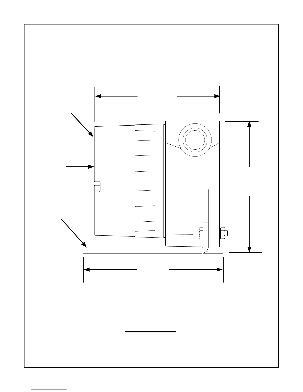
EX72 Camera:
MECHANICAL SPECIFICATIONS
EX72
Housing
Cover
Optional
Mounting
Bracket
5.63”
(143mm)
Base
5.94”
(151mm)
6.34”
(161mm)
Side View
3
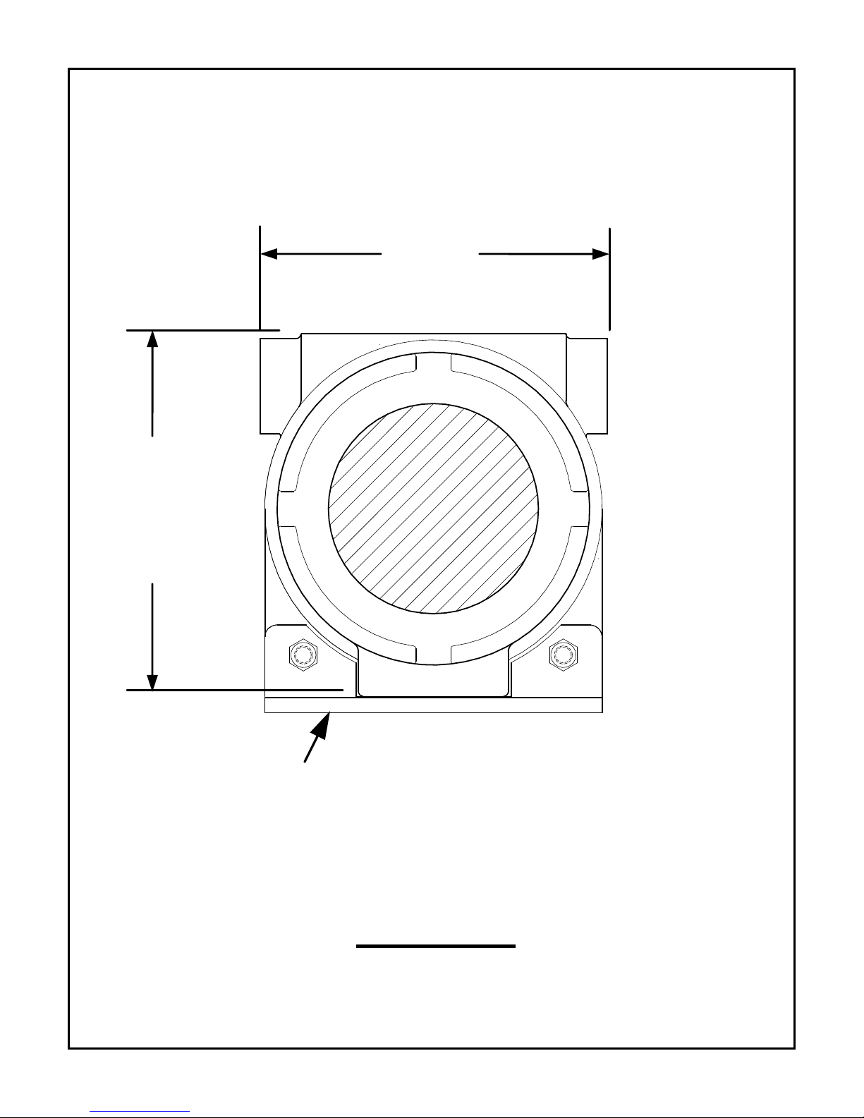
EX72 Camera:
MECHANICAL SPECIFICATIONS
5.63”
(143mm)
Housing
only
5.43”
(138mm)
Optional Mounting Bracket
and Hardware
Front View
4
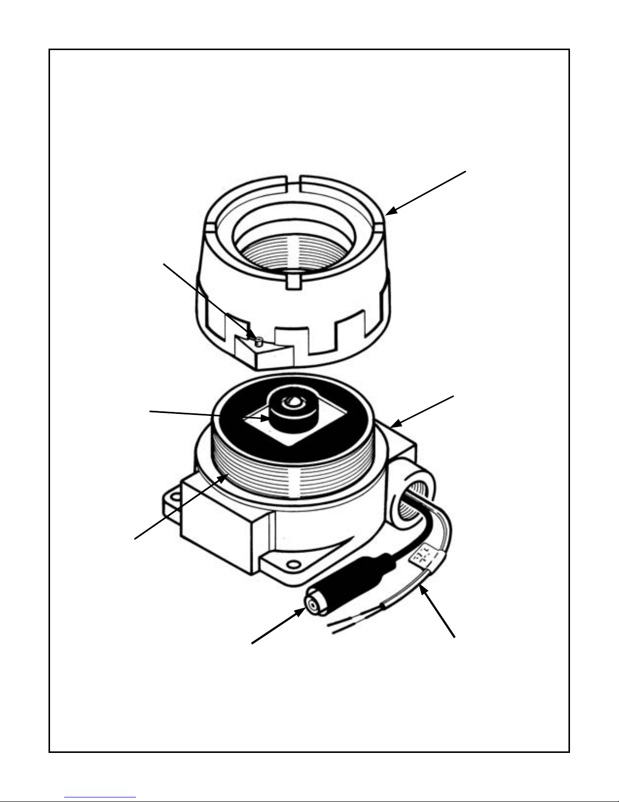
EX72 Camera:
INPUT / OUTPUT CABLES
Set-Screw
Camera
Module
Cover
Camera
Base
Casting
O-Ring
Gasket
VIDEO OUTPUT
POWER INPUT
BNC CABLE
5
CABLE

INITIAL PREPARATIONS
• The camera’s voltage regulator board
(VRB) accepts an input voltage of either
12V dc or 24V ac, and a range in-between,
from a regulated power supply.
• The VRB automatically switches between
ac or dc inputs, therefore no internal wiring
changes are necessary to accommodate
these input voltages.
• Determine the optimum location for the
camera.
Section 1: Mounting-Camera Housing.
• All cameras have been tested prior to
shipment.
GUIDELINES
The installation of the EX72 Camera is shown in
Sections 1 and 4 listed below.
It is important that these steps are followed in
sequence:
1. Mounting – Camera Housing
2. Voltage Input Connections
3. Camera Alignment
4. Camera Adjustments
6
1. MOUNTING - CAMERA HOUSING
Caution: Install with the appropriate screws
or drywall anchors to suit the mounting
surface. Select a suitable location that is
protected from accidental damage or
tampering, and environmental conditions
that could exceed the camera’s general
specifications.
See page 32.
Caution: Ensure the selected location is
protected from falling objects, accidental
contact with moving objects, and
unintentional interference from personnel.
Follow all applicable building codes.
7
 Loading...