

Bosch EX70MNX804-N, EX70MNX806-N, EX70MX404-N, EX70C704-N Installation Instructions Manual
S
INSTALLATION INSTRUCTION
Precision Engineered Opto-Electronics™
EX70 / 70N
Explosion Protected Camera
Please read this Instruction Booklet prior to installing the
EX70 and EX70N Explosion Protected Camera.
ATEX Approved or CSA Certified / UL Listed CLASS 2 power
adaptors must be used in order to comply with electrical safety
Only qualified personnel shall install any Bosch Security Systems,
Inc. surveillance product. any Bosch Security Systems, Inc. will not
be responsible for injuries or damages resulting from the improper
installation or use of any product sold by any Bosch Security
Systems, Inc., their agents,distributors, or dealers
IMPORTANT
WARNING !
standards.
EU Directives covered by this declaration:
72/9/EC Low Voltage Directives
89/336/EEC Electromagnetic Compatibility Directive
Class 2 circuits shall be supplied from a Class 2 transformer, or
a) A Class 2 power supply or device or
b) Where the voltage does not exceed 20 volts, a 5 ampere
.
94/9/EC Equipment or Protective System for use in
Potentially Explosive Atmospheres.
(maximum) mini circuit breaker or a 5 ampere noninterchangeable fuse.
Certifications / Compliance:
CSA-NRTL: MC 189936
Class: 2258 02
Process Control Equipment – For
Hazardous Locations
2258 82
Process Control Equipment – For
Hazardous Locations – Certified to US
Standards
Safety: Class I, Div 1, 2, Groups B,C,D
Class II, Div 1, 2, Groups E,F,G
Class III
T6 Temperature Code
Environmental: CSA / NEMA TYPE 4X
DEMKO: 07 ATEX 142765X
II2G Ex d IIc T6
ATEX Category 2 (Gas) equipment designed for
installation in Zone1. Protection by constructional safety
using flame proof enclosure, suitable for Coal Disulphide
environments with maximum equipment surface
temperature of 85°c

INDEX
Page
Description...................................................1
Unpacking....................................................2
Parts List......................................................2
Items Required for Installation.....................2
Initial Preparations.......................................3
Guidelines....................................................3
Section 1. Cover Removal...........................4
Section 2. Input Power Connections ...........6
Section 3. Mounting – Camera Base...........9
Section 4. Camera/LED Adjustments........11
Section 5. Camera Re-Assembly ..............15
Section 6. Troubleshooting, Camera.........20
Section 7. Troubleshooting, LEDs.............23
Section 8. General Specifications..............24

DESCRIPTION
The EX70 and EX70N Explosion Protected
Cameras have been designed for surveillance
applications in hazardous areas. Each camera’s
ATEX-rated housing consists of a heavy-duty
aluminum casting with a chemical resistant
viewing window. The housing is also NEMA
rated for watertight use.
The EX70 has been engineered for surveillance
reliability during daylight operation, while the
EX70N offers total surveillance protection during
day and night situations.
A voltage regulator circuit allows for 12V dc or
24V ac operation, and a range in between, also
providing protection from voltage surge,
transient spikes, and reverse voltage.
The EX70 and EX70N cameras are available in
several models designed to meet specif ic needs.
For additional information and specificati ons,
please contact your Bosch Security Systems
representative.
1

UNPACKING
Care should be taken when unpa cking the
shipped unit. Check the parts list and confirm all
items have been located. Inspect the equipment
thoroughly to ensure nothing was damaged in
transit.
Contact Bosch Security Systems if a problem is
noted. See the rear of the booklet for contact
numbers.
PARTS LIST (items supplied with unit)
• EX70/EX70N Camera
• Installation Instructions booklet
ITEMS REQUIRED FOR INSTALLATION
(not supplied with the shipped unit)
• Long shaft Philips screwdriver
• Regular Philips screwdriver
• Small slotted screwdriver
• Mounting hardware
*Ensure zone conditions are observed and regional
health & Safety regulations are applied.
2

INITIAL PREPARATIONS
• The camera voltage regulator board
(VRB) accepts an input voltage of either
12V dc or 24V ac, and a range in-between,
from a regulated power supply.
• The VRB automatically switches between
ac or dc inputs, therefore no internal wiring
changes are necessary to accommodate
these input voltages.
• Determine the optimum location for the
camera.
• All cameras have been tested prior to
shipment.
GUIDELINES
The installation of the EX70and EX70N is
explained in Sections 1 to 5 listed below.
It is important that these steps are followed in
sequence:
1. Cover Removal
2. Input Power Connections
3. Mounting - Camera Base
4. Camera / LED Array Adjustments
5. Camera Re-Assembly
3

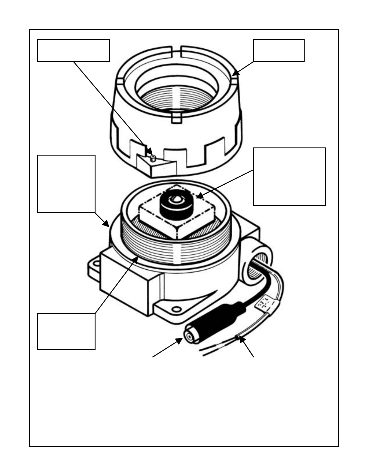
1. COVER REMOVAL
The camera’s cover must be removed prior to
adjustment for LED brightness or setting the
camera’s lens angle. The set-screw located at
the bottom of the cover casting is not tightened
at the factory and protrudes by 1/8" (3mm) in
order for the cover to be easily rotated.
Make sure the O-Ring gasket at the base of the
threads is not damaged or dislodged d uring the
cover’s removal process.
Refer to Figure 1 – 1.
Step 1.1 - Place the camera casting assembly
on a flat surface.
Step 1.2 - Firmly hold the base with one hand
and rotate the cover in a counter-
clockwise direction with the other
hand. Do not use a screwdriver or
other metal device during this
procedure.
Step 1.3 - Remove the cover and set it aside in
a safe place.
4
y
Camera
g
Body
Base
Castin
Cover Set-Screw
Camera
and LED
Array
Assembl
O-Ring
Gasket
Video Output Cable Power Input Cable
FIGURE 1 – 1
Cover Removal
5
 Loading...