

Bosch EX40N Installation Instructions Manual
INSTALLATION INSTRUCTIONS
EX40N
Ultra Vandal-Proof Dome Camera
MAN-40N-01

IMPORTANT SAFETY INSTRUCTIONS
1. Read these instructions.
2. Keep this instruction.
3. Heed all warnings.
4. Follow all instructions.
5. Clean only with dry cloth.
6. Do not block any ventilation openings. Install
in accordance with manufacturer instructions.
7. Do not install near any heat sources where the
temperature goes above the product rating.
8. Protect the cabling from being walked on or
pinched particularly at connection points and
where they exit from the apparatus.
9. Only use accessories specified by the
manufacturer.
10. Disconnect this apparatus during lightning
storms or when unused for long periods of
time if precautions are not taken to prevent
lightning/electrical damage to the product.

11. Refer all servicing to qualified service
personnel. Servicing is required when the
apparatus has been damaged in a way, such
as internal wiring is damaged, liquid has been
spilled or objects have fallen into the
apparatus, the apparatus has been exposed to
rain or moisture, does not operate normally, or
has been dropped
.

IMPORTANT
For best results, please read this Instruction Booklet prior to
installing the EX40N camera.
For best results in infrared image quality, when reassembling the
dome to the housing, make sure the foam donut is in tight 360
contact with the dome.
WARNING !
CSA Certified / UL Listed CLASS 2 power adaptors must be used
in order to comply with electrical safety standards.
12-24 VDC/VAC (60Hz), 10W
CSA Type 4
CAN/CSA 60065 – 03 + Amd 1
Audio, Video and Similar Electronic Apparatus – Safety Requirements
UL Std No. 60065 - 07
Audio, Video and Similar Electronic Apparatus – Safety Requirements
This Product Has Been Certified By CSA International To
Include the Health Care Facility Requirements Of UL 2044.
EU Directives covered by this declaration:
72/9/EC Low Voltage Directives
89/336/EEC Electromagnetic Compatibility Directive
This installation should be made by a qualified service person and
conform to all local codes. Bosch will not be responsible for
injuries or damages resulting from the improper installation or use
of any camera sold by Bosch, their agents, distributors or dealers.

NOTE: This equipment has been tested and found to
comply with the limits for a digital device, pursuant to
part 15 of the FCC rules. These limits are designed to
provide reasonable protection against harmful
interference in a residential installation. As part of it's
normal operation this device can generate radio
frequency energy and if not installed and used in
accordance with the installation manual may cause
interference to radio communications. However, there
is no guarantee that interference will not occur on a
particular installation. If the device does cause
interference to radio or television reception the user is
encouraged to try to correct the interference by one or
more of the following measures:
1) Fit Ferrite beads on all cable to and from the power
supply box, within the box walls.
2) Route the composite cable between the camera and
the power supply in steel conduit piping over the entire
run of the cable up to and including connection to a
deep conduit base fitted under the camera and a conduit
fitting adaptor in the wall of the PSU box.
3) Contact BOSCH Service Center for further advice.

INDEX – EX40N
Page
Description..................................................1
Unpacking...................................................2
Parts List.....................................................2
Items Required for Installation ....................2
Initial Preparations......................................3
Guidelines...................................................3
Section 1. Dome Removal ..........................4
Section 2. Input Power Connections...........6
Section 3. Mounting - Camera Base ...........9
Section 4. Adjustments............................. 15
Section 5. Camera Re-Assembly..............22
Section 6. Troubleshooting Guide.............24
Section 7. Template – Mounting Holes .....27
Section 8. General Specifications ............. 28

DESCRIPTION
The EX40N High Impact Dome Night Vision
Camera has been engineered for day/night
surveillance in hostile environments. Compact
and good looking, the camera features armourtough construction for protection against
vandalism or accidental damage.
An aluminum housing, CNC-machined from a
billet, with an impact resistant polycarbonate
dome and locking retaining ring, make it
extremely rugged and weather-tight.
For flexibility, the CCD Camera/LED Array can
be fully rotated using a unique “Pan-Tilt-Twist”
(PTT) mounting bracket.
A voltage regulator circuit allows for 12V DC or
24V AC operation, and a range in between, also
providing protection from voltage surge,
transient spikes, and reverse voltage.
The EX40N is available in several models
designed to meet specific needs.
1

UNPACKING
Care should be taken when unpacking the
shipped unit. Check the parts list and confirm all
items have been located. Inspect the equipment
thoroughly to ensure nothing was damaged in
transit.
Contact a Bosch Service Center if a problem is
noted, see the rear page of this booklet for
contact numbers.
PARTS LIST (items supplied with unit)
- Camera Assembly
- Half-tint dome bubble (installed)
- Clear dome bubble (spare)
- Installation Instructions booklet
- EX40N Plastic bag containing a Hex key and
one ½ NPT plug wrapped with Teflon tape
- Desiccant pack for moisture absorption (do not
remove)
ITEMS REQUIRED FOR INSTALLATION
(not supplied with unit)
- Philips, Robertson screwdrivers
- Silicone sealant and Teflon sealing tape
- Mounting screws, etc.
2

INITIAL PREPARATIONS
Determine the operating voltage at the
installation site. The camera’s Voltage
Regulator Board can accept a 12V DC or 24V
AC input. See Section 2, Input Power
Connections.
Determine the optimum location for the
camera. Section 3, Mounting-Camera Base.
All cameras have been tested prior to
shipment. After the wiring has been
reconnected, it is advisable to check the
camera’s operation before installation.
ESD protection – Cameras and circuit boards
are sensitive electronic components. It is
recommended to wear a ground strap to
ground any static charge. (Alternative: touch a
grounded metal plate for at least a minute
before proceeding with any disassembly)
GUIDELINES
The installation of the EX40N camera is explained
in Sections 1 to 5 listed below. It is important that
these steps are followed in sequence:
1. Dome Removal
2. Input Power Connections
3. Mounting - Camera Base
4. Adjustments
5. Camera Re-Assembly
3

1. DOME REMOVAL
The camera’s dome and its retaining ring must
be removed prior to mounting the camera or
performing any wiring disconnections and reconnections. The set-screws in the retaining ring
are not tightened in the factory and protrude by
1/8" (3mm) in order for the ring to be rotated.
Refer to Figure 1 - 1 on page 5.
Step 1.1 - Place the camera on a flat surface.
Step 1.2 - Press firmly on the dome with one
hand and rotate the retaining ring in
a counter-clockwise direction with
the other hand. Push against the
protruding set-screws with a finger
to rotate the ring. Do not use a
screwdriver or other metal device.
Step 1.3 - Remove the dome and the retaining
ring. Set them aside.
4
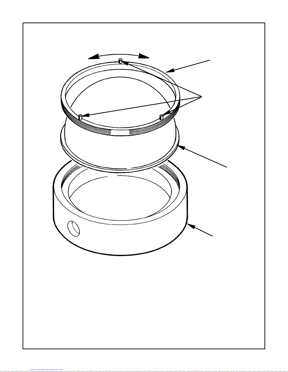
Loosen or tighten ring
Retaining
Ring
Set Screws
Dome
FIGURE 1 – 1
Dome Removal
Camera
Base
5
 Loading...