

Page 1
Precision Engineered Opto-Electronics™
INSTALLATION INSTRUCTIONS
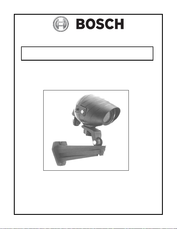
EX10 Waterproof Camera
MAN-10-05
Page 2

IMPORTANT SAFETY INSTRUCTIONS
1. Read these instructions.
2. Keep this instruction.
3. Heed all warnings.
4. Follow all instructions.
5. Do not use this apparatus near water.
6. Clean only with dry cloth.
7. Do not block any ventilation openings. Install
in accordance with manufacturer instructions.
8. Do not install near any heat sources such as
radiators, heat registers, stoves or other
apparatus (including amplifiers) that produce
heat.
9. Do not defeat the safety purpose of the
polarized or grounding-type plug. A polarized
plug has two blades with one wider than the
other. A grounding type plug has two blades
and a third grounding prong. The wide blade
or the third prong is provided for your safety. If
Page 3

the provided plug does not fit into your outlet,
consult an electrician for replacement of the
obsolete outlet.
10. Protect the power cord from being walked on
or pinched particularly at plugs, convenience
receptacles, and the power where they exit
from the apparatus.
11. Only use attachments/accessories specified by
the manufacturer.
12. Use only with the cart, stand, tripod, bracket,
or table specified by the manufacturer, or sold
with the apparatus. When a cart is used, use
caution when moving the cart/apparatus
combination to avoid injury from tip-over.
13. Unplug this apparatus during lightning storms
or when unused for long periods of time.
14. Refer all servicing to qualified service
personnel. Servicing is required when the
apparatus has been damaged in a way, such
as power-supply cord or plug is damaged,
liquid has been spilled or objects have fallen
into the apparatus, the apparatus has been
exposed to rain or moisture, does not operate
normally, or has been dropped.
Page 4
IMPORTANT
For best results, please read this Instruction Booklet prior
to installing the EX10 camera.
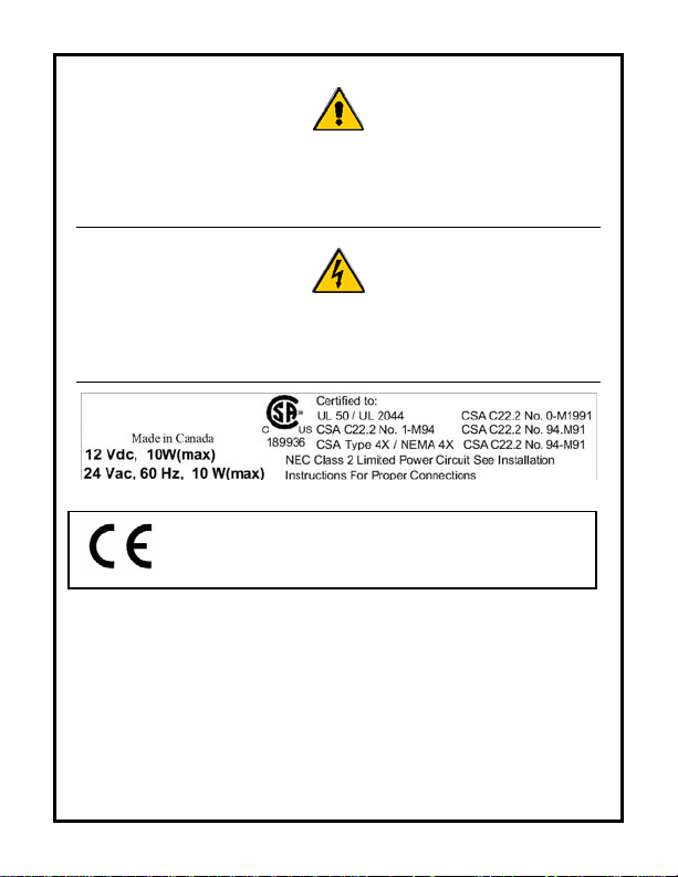
WARNING !
CSA Certified / UL Listed CLASS 2 power adaptors must be used
in order to comply with electrical safety standards.
EU Directives covered by this declaration:
72/9/EC Low Voltage Directives
89/336/EEC Electromagnetic Compatibility Directive
Only qualified personnel shall install any
Bosch Security Systems, Inc. camera.
Bosch Security Systems, Inc. will not be responsible for injuries
or damages resulting from the improper installation or use of any
product sold by Bosch Security Systems, Inc their agents,
distributors or dealers.
Page 5

NOTE: This equipment has been tested and found to
comply with the limits for a digital device, pursuant to
part 15 of the FCC rules. These limits are designed to
provide reasonable protection against harmful
interference in a residential installation. As part of its’
normal operation this device can generate radio
frequency energy and if not installed and used in
accordance with the installation manual may cause
interference to radio communications. However, there
is no guarantee that interference will not occur on a
particular installation. If the device does cause
interference to radio or television reception the user is
encouraged to try to correct the interference by one or
more of the following measures:
1) Fit Ferrite beads on all cable to and from the power
supply box, within the box walls.
2) Route the composite cable between the camera and
the power supply in steel conduit piping over the entire
run of the cable up to and including connection to a
deep conduit base fitted under the camera and a
conduit fitting adaptor in the wall of the PSU box.
3) Contact BOSCH Service Center for further advice.
Page 6

INDEX
Page
Description...................................................1
Unpacking....................................................2
Parts List......................................................2
Items Required for Installation.....................2
Initial Preparations.......................................3
Guidelines....................................................3
Section 1. Housing Separation....................4
Section 2. Input Power Connections ...........7
Section 3. Camera Re-Assembly ................8
Section 4. Camera Mounting.....................10
Section 5. Troubleshooting Guide.............13
Section 6. General Specifications..............15
Page 7

DESCRIPTION
The EX10 waterproof camera consists of a twopiece injection molded watertight housing with a
tough polycarbonate viewing window.
This compact egg-shaped camera can be used for
applications wherever environmentally sealed CCD
cameras are required. The camera is especially
suited for wash-down applications in food
processing and industrial clean-room installations or
very cold conditions.
The EX10 can be ordered in monochrome or color
versions. A rigid nylon mounting bracket is included
with the camera, however, an optional metal Ubracket is also available.
A voltage regulator circuit automatically allows for
12V dc or 24V ac operation without any wiring
changes. Its wider voltage range also provides
protection from voltage surge, transient spikes, and
reverse voltage.
The EX10 is available in several models to meet
individual requirements or specific needs.
- 1 -
Page 8

UNPACKING
Care should be taken when unpacking. Check the
parts list and confirm all items have been located.
Inspect the equipment thoroughly to ensure nothing
was damaged in transit.
Contact BOSCH Service Center if a problem is
noted, see the rear page of this booklet for contact
numbers.
PARTS LIST (items supplied with unit)
- EX10 camera unit
- Installation Instructions booklet
- Mounting bracket
ITEMS REQUIRED FOR INSTALLATION
(not supplied with unit)
- Small slotted screwdriver
- Philips screwdriver
- Hardware for camera mounting (screws,
washers, etc.)
- 2 -
Page 9

INITIAL PREPARATIONS
Determine the operating voltage at the
installation site. The camera has been prewired for 12Vdc or 24V ac operation before
shipment. See Section 2 – Input Power
Connections.
Determine the optimum location for the
camera. See Section 4 - Camera Mounting
All cameras have been tested prior to
shipment. After the wiring has been
reconnected, it is advisable to check the
camera’s operation before installation.
GUIDELINES
The installation of the EX10 camera is explained
in Sections 1 to 4 listed below.
It is important that these steps are followed in
sequence:
1. Housing Separation
2. Input Power Connections
3. Camera Re-Assembly
4. Camera Mounting
- 3 -
Page 10

1. HOUSING SEPARATION
Separating the two halves of the camera
housing allows access to the Voltage Regulator
Board (VRB) and camera. This is only used as a
reference since all the settings are preset at the
factory.
Step 1.1 - Remove the two housing screws
located on each side of the EX10
camera housing.
Refer to Figure 1-1 on page 5.
Step 1.2 - Slide both sections of the housing
apart without damaging the camera
connecting leads. Disconnect the
camera connector to completely
separate the two halves of the
housing. Ensure that the “O” ring
gasket does not pull out of its
groove during separation. If the
gasket does separate, it is important
that it is not lost. Re-insertion the
gasket into the groove.
Refer to Figure 1-2 on page 6.
- 4 -
Page 11

FIGURE 1 – 1
Housing
Step 1.1 - Screw Removal
- 5 -
Page 12

FIGURE 1 – 2
Housing
Step 1.2 - Housing Separation
- 6 -
Page 13

2. INPUT POWER CONNECTIONS
The camera unit is pre-connected with an
electrically isolated power board for 24V ac or
12V dc operation with no wiring change or wiring
polarity. See Figure 2-1 on page 7 for wiring
details.
Note
:
Input voltage is 10.5VDC to 40VDC for DC input.
The AC input range is 12VAC to 28VAC.
Electrically Isolated Board
Power
IN
Power
OUT
FIGURE 2 - 1
12VDC or 24VAC
- 7 -
Page 14

3. CAMERA RE-ASSEMBLY
Make sure all wires are properly connected and
tightened into the terminal blocks as explained in
Section 2.
Step 3.1 - Check that the orange “O” ring
gasket in the rear half of the camera
housing has not been dislodged or
distorted.
Step 3.2 - Re-connect the camera wiring
harness plug back into its connector
on the Voltage Regulator Board.
Step 3.3 - Carefully slide the two halves of the
camera housing together, making
sure that the “O” ring gasket seats
properly and the camera harness
wires are not pinched.
Refer to Figure 3-1 on page 9.
Step 3.4 - Once the front and rear sections are
mated, insert and tighten the
housing screws into each side.
- 8 -
Page 15

FIGURE 3 – 1
Camera Housing Re-assembly
Steps 3.1, 3.2, 3.3
- 9 -
Page 16

4. CAMERA MOUNTING
Caution: The selected mounting location should
not place the camera in a situation where its
environmental specifications could be exceeded.
See Section 6, page 15.
The supplied mounting bracket contains two
holes for attachment to any suitable flat surface.
The type of mounting hardware is dependent on
the selected surface. e.g., wood, metal, plaster,
gyproc, etc.
Refer to Figure 4-1 on page 11.
Once the bracket has been secured, attach the
camera housing to the adjustable camera
bracket with the supplied mounting knob. Adjust
for desired camera viewing angle and tighten the
screw located at tip of the mounting bracket.
Refer to Figure 4-2 on page 12.
Note: The power / video cable should be
secured in a way that no undue stress is placed
on the camera housing or its mounting bracket.
- 10 -
Page 17

FIGURE 4 – 1
Mounting Bracket
- 11 -
Page 18

FIGURE 4 – 2
Camera mounting
- 12 -
Page 19

5. TROUBLESHOOTING GUIDE
PROBLEM POSSIBLE
CAUSE
No Video 1. Power Supply:
-Connections….
-Voltage Range...
2. Video
Connections
:
LIKELY
SOLUTION
Check input power
connections at the
cable leads. Check
for loose wires.
If connected to DC,
check voltage input
range of 10.5 – 40 V.
If connected to AC,
check input voltage
range of 12 – 28 V.
Measure the voltage
at the circuit board’s
Input Power
Connector.
Determine if wiring
polarity at “Video
Connector” terminal
block is correct.
Check BNC
Connector.
- 13 -
Page 20

No Video
__________
Poor
Picture
Quality
Snowy
Image
Horizontal
Scan Lines,
Rolling Up
or Down.
(cont’d.)
2. Video
Connections:
(cont’d.)
________________
Poor Video Signal
Noisy Power Supply
Ground Looping on
24V ac.
- 14 -
If still no video,
connect the camera
directly to the
monitor. Check the
video signal. If okay,
the problem is with
the interconnections.
If still no video,
contact BOSCH
Service Center. See
rear page of this
manual for contact
information.
_________________
Ensure video cable is
correctly matched
and terminated with
75 ohms at each
end. Make sure
video cables are
similar types.
Check connections.
Relocate or replace
power supply.
Check the coax
cable shield is not
touching ground, e.g.
at couplings.
Page 21

6. GENERAL SPECIFICATIONS
TV System...... Color – NTSC (PAL optional)
Monochrome – EIA (CCIR optional)
Video Signal Output............ 1 V p-p, 75 Ohm
Operational Range................-60°C to +60°C
(-76°F to 140°F)
Power Supply (dc) ....................... 10.5 – 40V
Power Supply (ac) .......................... 12 – 28V
Housing......................Injection molded nylon
Viewing window.......... Polycarbonate (clear)
Mounting bracket................Reinforced nylon
Dimensions......5.19”L(132mm)x 3”D(76mm)
Weight...................................0.83 lbs. (375g)
Subject to Change Without Notice.
- 15 -
Page 22

Note:
Page 23

Note:
Page 24

Americas
Bosch Security Systems, Inc.
850 Greenfield Road
Lancaster, Pennsylvania 17601
USA
Telephone+1 888-289-0096
Fax +1 585-223-9180
Email: security.sales@us.bosch.com
www.boschsecurity.us
Europe, Middle East, Africa:
Bosch Security Systems B.V.
P.O. Box 80002
5600 JB Eindhoven,
The Netherlands
Phone: + 31 40 2577 284
Fax: +31 40 2577 330
emea.securitysystems@bosch.com
www.boschsecurity.com
© Bosch Security Systems, Inc. 2009; Data subject to change
without notice.
Asia-Pacific:
Bosch Security Systems Pte Ltd
38C Jalan Pemimpin
Singapore 577180
Phone: +65 6319 3450
Fax: +65 6319 3499
apr.securitysystems@bosch.com
www.boschsecurity.com
 Loading...