

Bosch EVX-50E, EVX-25E, EVX-100E Installation Manual

EVX-25E / EVX-50E / EVX-100E
EXPANDER
INSTALLATION INSTRUCTIONS
The EVX-25E/ EVX-50E / EVX-100E is a self contained amplifier, tone generator, power
supply and supervisory interface. It is designed to be used in conjunction with the EVAX 25/
50 /100 to provide additional speaker output power. It may also be used stand-alone in
conjunction with a Fire Alarm Control Panel to provide voice evacuation where an automatic
message is not desired.
Installation and operation is identical to the EVAX 25/ 50 /100 (see Installation Instructions
P/N 1-5001 Rev. D). With the exception that no digital message is present. When used in
conjunction with the EVAX 25/ 50/100 the Expander will act as a slave reproducing the tone
and message generated by the master. When used as a stand-alone, the Expander will
connect to the FACP exactly as the EVAX 25/ 50/100 does to provide automatic tone in
alarm and voice override capability.
All terminal designations and volume controls are identical to the EVAX 25/ 50/ 100. One
exception is that on the Expander SN1 determines Tone, Master/Slave, Battery and
Microphone supervision. There is no SN2.
Factory defaults are:
Expander as Slave
1 = OFF Temporal Whoop Signal
2 = OFF
3 = OFF
4 = OFF
5 = OFF
6 = OFF Slave (ON = Master setting)
7 = ON Battery connected (OFF = No Batteries)
8 = OFF No Mic (ON = Mic connected)
Expander as Master / Stand-Alone
SN1 Tone Selection
SW 1/2/3 Sets the tone generated by the amplifier
when it is operating in Master mode.
7 Settings: 0/0/0 Temporal Whoop
1 = OFF Temporal Whoop Signal
2 = OFF
3 = OFF
4 = OFF
5 = OFF
6 = ON Master setting
7 = ON Battery connected (OFF = No Batteries)
8 = ON Mic connected
Switch Network Detail
1 8
1/0/0 Hi / Lo Tone
0/1/0 Sine Wave
0/0/1 1 kHz Sine Wave
1/1/0 March Time Beep (880 Hz)
1/0/1 Slow Whoop
0/1/1 Code 3 Beep
OFF = 0 (UP)
ON = 1 (DOWN)
For ratings and specifications see Evax 25/50/100 Installation Instructions P/N 1-5001 Rev. F
P/N B-5002 Rev. E
Page 1 of 2
130 Perinton Parkway, Fairport, NY 11450
Customer Service: (800) 289-0096
Technical Support: (888) 886-6189
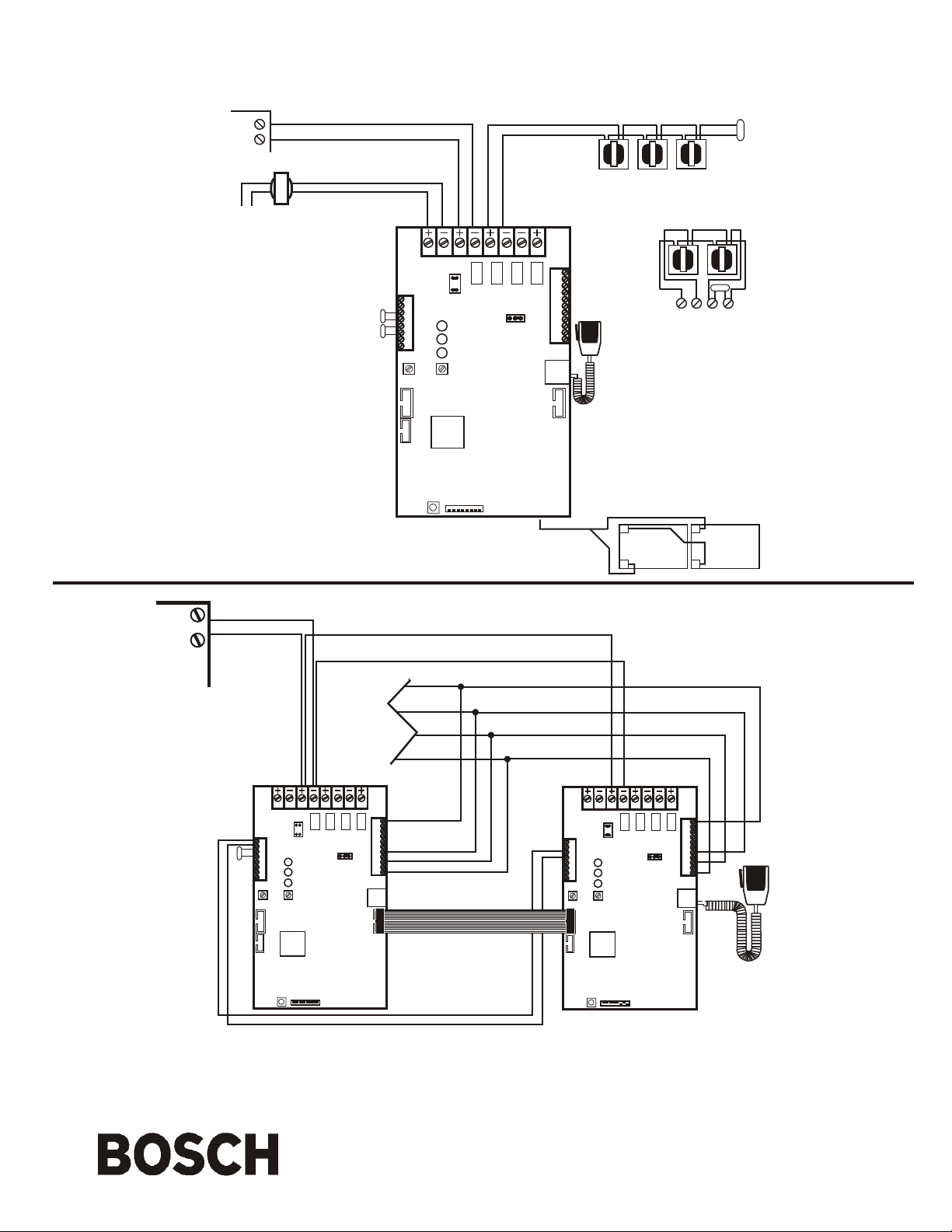
FIRE ALARM CONTROL PANEL
SIGNAL
CIRCUIT
ALARM POLARITY
INPUT POWER
120 VAC
Supervised
Non-Power Limited
EVX-25E / 50E / 100E
FIRE ALARM CONTROL PANEL
SIGNAL
CIRCUIT
ALARM
POLARITY
Field wiring connections:
#6-32 wire clamp screw 14-18 AWG
#8-32 wire clamp screw 12-18 AWG
Horizontal wire entry terminal 18-26 AWG
Wire gauge determined by circuit load
-
+
EVAX 25E / 50E / 100E
_
Supervised - Power Limited
+
Supervised - Power Limited
XFMR
FACP
EOLR
MATCHING
EOLR
(SPEAKER
CIRCUIT)
TYPICAL INSTALLATION
TB1
1 2 345 6 7 8
1
2
1
TB3
J1
2
E
3
O
L
4
E
5
FAULT
YEL
O
6
L
GRN
NORMAL
7
8
RED
ALARM
MESSAGE
MIC
GAIN
GAIN
Supervised - Power Limited
CLASS “B” (Style “Y”)
WIRING
Standard Life Safety Speakers, Strobes connected and powered separately
Break wire to maintain supervision. Do not loop wire around speaker terminals
TB2
11
10
9
8
7
6
J2
5
4
1 2 3
3
2
1
P2
FF
II
RR
EE
For Fire Emergency Use Only
II
II
RR
RR
EE
EE
CLASS “A” (Style “Z”)
WIRING
FF
II
RR
EE
TB1
5 6 7 8
Supervised - Power Limited
FF
FF
E
O
EOLR
L
FF
II
RR
EE
EOL
Field wiring connections:
#6-32 wire clamp screw 14-18 AWG
#8-32 wire clamp screw 12-18 AWG
Horizontal wire entry terminal 18-26 AWG
Wire gauge determined by circuit load
SN1
S1
Battery Wire Harness
Supervised - Non Power Limited
Charging Current 1A max.
-
12V
Battery
+
Jumper Wire is Provided
-
12V
Battery
+
EVAX 25E / 50E / 100E
Master / Slave Connection Detail
Non-Supervised - Power Limited
Non-Supervised wiring
TO
ADDITIONAL
EXPANDERS
must be only run in the
same cabinet or between
cabinets which are piped
together within the same
room at a maximum of
20’.
TB1
1 2 345 6 7 8
1
2
1
TB3
J1
2
E
3
O
L
4
5
FAULT
YEL
FACP
6
EOLR
GRN
NORMAL
7
8
RED
ALARM
MESSAGE
MIC
GAIN
GAIN
SLAVE MASTER
EVX-25E / 50E/ 100E EVX-25E / 50E/ 100E
SN1
S1
J2
1 2 3
TB2
11
10
9
8
7
6
5
4
3
2
1
P2
14 pin ribbon cable
(factory supplied) may be used
in place of hard wired connections
on TB2-11,5,3,1
Supervised Power Limited
TB1
1 2 345 6 7 8
1
2
1
TB3
J1
2
3
4
5
FAULT
YEL
6
GRN
NORMAL
7
8
RED
ALARM
MESSAGE
MIC
GAIN
GAIN
SN1
S1
1 2 3
TB2
11
10
9
8
7
6
J2
5
4
3
2
1
P2
Master
*NOTE: Switch SN1-6, SN1-8 must be in OFF position for all Slave modules. All Power and Speaker connections remain unchanged.
J1 Shorting blocks removed from slave units for pass-through supervision.
P/N B-5002 Rev. E
Page 2 of 2
130 Perinton Parkway, Fairport, NY 11450
Customer Service: (800) 289-0096
Technical Support: (888) 886-6189
 Loading...