

Bosch DIP-7280-00N, DIP-7284-8HD, DIP-7288-8HD, DIP-728C-8HD Users manual
DIVAR IP all‑in‑one 7000 2U
DIP‑7280‑00N | DIP‑7284‑8HD | DIP‑7288‑8HD | DIP‑728C‑8HD
en
Installation manual


DIVAR IP all-in-one 7000 2U Table of contents | en 3
Table of contents
1
Safety 5
1.1 Safety message explanation 5
1.2 General safety precautions 5
1.3 Electrical safety precautions 8
1.4 ESD precautions 9
1.5 Operating precautions 9
1.6 Notices 9
1.7 FCC and ICES compliance 10
1.8 Data security precautions 11
2
Introduction 12
2.1 Parts included 12
2.2 Product registration 12
3
System overview 13
3.1 Chassis components 13
3.2 Device views 14
3.3 Control panel elements 15
3.4 Hard drive carrier LEDs 17
3.5 Power supply LEDs 17
4
Rack installation 18
4.1 Unpacking the system 18
4.2 Preparing for installation 18
4.2.1 Choosing the installation location 18
4.2.2 Rack precautions 18
4.2.3 General system precautions 19
4.2.4 Installation considerations 19
4.3 Rack mounting instructions 19
4.3.1 Separating the sections of the rack rails 20
4.3.2 Installing the inner rails on the chassis 20
4.3.3 Installing the outer rails to the rack 21
4.3.4 Installing the chassis in the rack 21
4.4 Turning on the system 23
5
System setup 24
5.1 Default settings 24
5.2 Prerequisites 24
5.3 Operating modes 24
5.4 Preparing hard drives for video recording 25
5.4.1 Configuring hard drives 25
5.4.2 Formatting hard drives 25
5.5 Starting the application 26
5.5.1 Operating as full video recording and management system 27
5.5.2 Operating as pure video recording system 27
5.5.3 Operating as iSCSI storage expansion 27
5.6 Using BVMS Config Wizard 27
5.7 Adding additional licenses 28
5.8 Using BVMS Operator Client 28
6
Remote connection to the system 30
6.1 Protecting the system from unauthorized access 30
6.2 Setting up port forwarding 30
Bosch Security Systems B.V.
Installation manual
2021.03 | V2 | DOC

4 en | Table of contents DIVAR IP all-in-one 7000 2U
6.3 Choosing an appropriate client 30
6.3.1 Remote connection with Operator Client 30
6.3.2 Remote connection with Video Security App 30
6.4 Installing an Enterprise Management Server 31
7
8
RAID setup 32
Troubleshooting 33
8.1 Overheating 33
9
Maintenance 34
9.1 Replacement components 34
9.2 Removing power from the system 34
9.3 Removing the chassis cover 34
9.4 Installing a SATA hard drive 35
9.4.1 Removing a hard drive carrier from a hard drive bay 36
9.4.2 Installing a hard drive into a hard drive carrier 36
9.4.3 Installing a hard drive carrier into a front drive bay 37
9.5 Identifying a faulty SSD drive 38
9.6 Installing a SSD hard drive into a rear drive bay 38
9.6.1 Removing a hard drive carrier from a rear hard drive bay 38
9.6.2 Installing a hard drive into a rear hard drive carrier 39
9.6.3 Installing a hard drive carrier into a rear hard drive bay 39
9.7 Replacing the DVD ROM drive 40
9.8 Replacing the front port panel 40
9.9 Installing the motherboard 41
9.10 Installing a graphics card 41
9.11 Installing a sound card 41
9.12 Installing the air shroud 42
9.13 Replacing a system fan 43
9.14 Replacing the power supply 44
9.15 Replacing the power distributor 45
9.16 Monitoring the system 46
9.17 Recovering the unit 46
9.18 Service and repair 47
10
Additional information 48
10.1 Additional documentation and client software 48
10.2 Support services and Bosch Academy 48
2021.03 | V2 | DOC
Installation manual
Bosch Security Systems B.V.
DIVAR IP all-in-one 7000 2U Safety | en 5
!
!
i
!
!
1 Safety
Observe the safety precautions in this chapter.
1.1 Safety message explanation
Warning!
Indicates a hazardous situation which, if not avoided, could result in death or serious injury.
Caution!
Indicates a hazardous situation which, if not avoided, could result in minor or moderate
injury.
Notice!
Indicates a situation which, if not avoided, could result in damage to the equipment or
environment, or data loss.
1.2 General safety precautions
Follow these rules to ensure general safety:
– Keep the area around the system clean and free of clutter.
– Place the chassis top cover and any system components that have been removed away
from the system on a table so that they won't accidentally be stepped on.
– While working on the system, do not wear loose clothing such as neckties and
unbuttoned shirt sleeves, which can come into contact with electrical circuits or be
pulled into a cooling fan.
– Remove any jewelry or metal objects from your body, which are excellent metal
conductors that can create short circuits and harm you if they come into contact with
printed circuit boards or areas where power is present.
– After accessing the inside of the system, close the system back up and secure it to the
rack unit after ensuring that all connections have been made.
– The system is heavy when fully loaded. When lifting the system, two people at either end
should lift slowly with their feet spread out to distribute the weight. Always keep your
back straight and lift with your legs.
Caution!
Installation should only be performed by qualified service personnel in accordance with
applicable local codes.
Caution!
The Low Voltage power supply unit must comply with EN/UL 60950. The power supply must
be a SELV-LPS unit or a SELV - Class 2 unit (Safety Extra Low Voltage - Limited Power
Source).
Bosch Security Systems B.V.
Installation manual
2021.03 | V2 | DOC
6 en | Safety DIVAR IP all-in-one 7000 2U
!
!
!
!
!
i
i
Warning!
Interruption of mains supply:
Voltage is applied as soon as the mains plug is inserted into the mains socket.
However, for devices with a mains switch, the device is only ready for operation when the
mains switch (ON/OFF) is in the ON position. When the mains plug is pulled out of the
socket, the supply of power to the device is completely interrupted.
Warning!
Removing the housing:
To avoid electric shock, the housing must only be removed by qualified service personnel.
Before removing the housing, the plug must always be removed from the mains socket and
remain disconnected while the housing is removed. Servicing must only be carried out by
qualified service personnel. The user must not carry out any repairs.
Warning!
Power cable and AC adapter:
When installing the product, use the provided or designated connection cables, power cables
and AC adaptors. Using any other cables and adaptors could cause a malfunction or a fire.
Electrical Appliance and Material Safety Law prohibits the use of UL or CSA-certified cables
(that have UL/CSA shown on the code) for any other electrical devices.
Warning!
Lithium battery:
Batteries that have been inserted wrongly can cause an explosion. Always replace empty
batteries with batteries of the same type or a similar type recommended by the manufacturer.
Handle used batteries carefully. Do not damage the battery in any way. A damaged battery
may release hazardous materials into the environment.
Dispose of empty batteries according to the manufacturer's instructions, or local directives.
Warning!
Handling of lead solder materials used in this product may expose you to lead, a chemical
known to the State of California to cause birth defects and other reproductive harm.
Notice!
Electrostatically sensitive device:
To avoid electrostatic discharges, the CMOS/MOSFET protection measures must be carried
out correctly.
When handling electrostatically sensitive printed circuits, grounded anti-static wrist bands
must be worn and the ESD safety precautions observed.
Notice!
Installation should only be carried out by qualified customer service personnel in accordance
with the applicable electrical regulations.
2021.03 | V2 | DOC
Read, follow, and retain for future reference all of the following safety instructions. Follow all
warnings before operating the device.
– Clean only with a dry cloth. Do not use liquid cleaners or aerosol cleaners.
– Do not install device near any heat sources such as radiators, heaters, stoves, or other
equipment (including amplifiers) that produce heat.
Installation manual
Bosch Security Systems B.V.

DIVAR IP all-in-one 7000 2U Safety | en 7
– Never spill liquid of any kind on the device.
– Take precautions to protect the device from power and lightning surges.
– Unless qualified, do not attempt to service a damaged device yourself. Refer all servicing
to qualified service personnel.
– Install in accordance with the manufacturer's instructions in accordance with applicable
local codes.
– Use only attachments/accessories specified by the manufacturer.
– Protect all connection cables from possible damage, particularly at connection points.
– Do not defeat the safety purpose of a polarized or ground‑type plug.
– Permanently connected devices must have an external, readily operable mains plug or
all‑pole mains switch in accordance with installation rules.
– Pluggable devices must have an easily accessible socket-outlet installed near the
equipment.
– Unplug the unit from the outlet before cleaning. Follow any instructions provided with the
unit.
– Any openings in the unit enclosure are provided for ventilation to prevent overheating and
ensure reliable operation. Do not block or cover these openings.
– If you install this device in an enclosure, make sure the enclosure is properly ventilated
according to the manufacturer’s instructions.
– Install the unit only in a dry, weather-protected location.
– Do not use this unit near water, for example near a bathtub, washbowl, sink, laundry
basket, in a damp or wet basement, near a swimming pool, in an outdoor installation, or
in any area classified as a wet location.
– To reduce the risk of fire or electrical shock, do not expose this unit to rain or moisture.
– Never push objects of any kind into this unit through openings as they may touch
dangerous voltage points or short-out parts that could result in a fire or electrical shock.
– Power supply cords should be routed so that they are not likely to be walked on or
pinched by items placed upon or against them, playing particular attention to cords and
plugs, convenience receptacles, and the point where they exit from the appliance.
– Operate the unit only from the type of power source indicated on the label. Use only the
power supply provided or power supply units with UL approval and a power output
according to LPS or NEC Class 2.
– Do not open or remove the cover to service this unit yourself. Opening or removing covers
may expose you to dangerous voltage or other hazards. Refer all servicing to qualified
service personnel.
– Be sure the service technician uses replacement parts specified by the manufacturer.
Unauthorized substitutions could void the warranty and cause fire, electrical shock, or
other hazards.
– Do safety inspections after service or repairs to the device to make sure the device
operates properly.
– Observe the relevant electrical engineering regulations.
– When installing in a switch cabinet, ensure that the unit and the power supply units have
sufficient grounding.
– Connect the unit to an earthed mains socket.
– Use proper CMOS/MOS-FET handling precautions to avoid electrostatic discharge (ESD).
– For protection of the device, the branch circuit protection must be secured with a
maximum fuse rating of 16A. This must be in accordance with NEC800 (CEC Section 60).
– Disconnect the power before moving the unit. Move the unit with care. Excessive force or
shock may damage the unit and the hard disk drives.
Bosch Security Systems B.V.
Installation manual
2021.03 | V2 | DOC

8 en | Safety DIVAR IP all-in-one 7000 2U
!
– All the input/output ports are Safety Extra Low Voltage (SELV) circuits. SELV circuits
should only be connected to other SELV circuits.
– If safe operation of the unit cannot be ensured, remove it from service and secure it to
prevent unauthorized operation. In such cases, have the unit checked by Bosch Security
Systems.
– Disconnect power supply and arrange for the device to be serviced by qualified personnel
in the following cases, because safe operation is no longer possible:
– The power cable/plug is damaged.
– Liquids or foreign bodies have entered the device.
– The device has been exposed to water or extreme environmental conditions.
– The device is faulty despite correct installation/operation.
– The device has fallen from a height, or the housing has been damaged.
– The device was stored over a long period under adverse conditions.
– The device performance is noticeably changed.
1.3 Electrical safety precautions
Basic electrical safety precautions should be followed to protect you from harm and the
system from damage:
– Be aware of the locations of the power on/off switch on the chassis as well as the room's
emergency power-off switch, disconnection switch or electrical outlet. If an electrical
accident occurs, you can then quickly remove power from the system.
– Do not work alone when working with high voltage components.
– Disconnect the power cables before installing or removing any components from the
computer, including the backplane. When disconnecting power, you should first turn off
the system and then unplug the power cords from all the power supply modules in the
system.
– Disconnect the power cable before installing or removing any cables from the backplane.
– When working around exposed electrical circuits, another person who is familiar with the
power-off controls should be nearby to switch off the power if necessary.
– Use only one hand when working with powered-on electrical equipment. This is to avoid
making a complete circuit, which will cause electrical shock. Use extreme caution when
using metal tools, which can easily damage any electrical components or circuit boards
they come into contact with.
– The power supply power cords must include a grounding plug and must be plugged into
grounded electrical outlets. The unit has more than one power supply cord. Disconnect
both power supply cords before servicing to avoid electrical shock.
– Make sure that the backplane is securely and properly installed on the motherboard to
prevent damage to the system due to power shortage.
– Mainboard replaceable soldered-in fuses: Self-resetting PTC (Positive Temperature
Coefficient) fuses on the mainboard must be replaced by trained service technicians only.
The new fuse must be the same or equivalent as the one replaced. Contact technical
support for details and support.
2021.03 | V2 | DOC
Caution!
Replaceable batteries
Risk of explosion if battery is replaced by an incorrect type. Dispose of used batteries
according to the manufacturer's instructions.
Installation manual
Bosch Security Systems B.V.
DIVAR IP all-in-one 7000 2U Safety | en 9
!
i
i
Caution!
DVD-ROM Laser: To prevent direct exposure to the laser beam and hazardous radiation
exposure, do not open the enclosure or use the unit in any unconventional way.
1.4 ESD precautions
Notice!
Electrostatic Discharge (ESD) can damage electronic components. To prevent damage to your
system, it is important to handle the electronic components very carefully.
Electrostatic Discharge (ESD) is generated by two objects with different electrical charges
coming into contact with each other. An electrical discharge is created to neutralize this
difference, which can damage electronic components and printed circuit boards. The
following measures are generally sufficient to neutralize this difference before contact is made
to protect your equipment from ESD:
– Do not use mats designed to decrease electrostatic discharge as protection from
electrical shock. Instead, use rubber mats that have been specifically designed as
electrical insulators.
– Use a grounded wrist strap designed to prevent static discharge.
– Keep all components and printed circuit boards (PCBs) in their antistatic bags until ready
for use.
– Touch a grounded metal object before removing the board from the antistatic bag.
– Do not let components or printed circuits boards come into contact with your clothing,
which may retain a charge even if you are wearing a wrist strap.
– Handle a board by its edges only. Do not touch its components, peripheral chips, memory
modules or contacts.
– When handling chips or modules, avoid touching their pins.
– Put the mainboard and peripherals back into their antistatic bags when not in use.
– For grounding purposes, make sure your computer chassis provides excellent
conductivity between the power supply, the case, the mounting fasteners and the
mainboard.
1.5 Operating precautions
The chassis cover must be in place when the system is operating to assure proper cooling. Out
of warranty damage to the system can occur if this practice is not strictly followed.
Note:
Please handle used batteries carefully. Do not damage the battery in any way. A damaged
battery may release hazardous materials into the environment. Do not discard a used battery
in the garbage or a public landfill. Please comply with the regulations set up by your local
hazardous waste management agency to dispose of your used battery properly.
1.6 Notices
Notice!
This is a class A product. In a domestic environment this product may cause radio
interference, in which case the user may be required to take adequate measures.
Bosch Security Systems B.V.
Installation manual
2021.03 | V2 | DOC
10 en | Safety DIVAR IP all-in-one 7000 2U
i
i
!
Notice!
Video loss is inherent to digital video recording; therefore, Bosch Security Systems cannot be
held liable for any damage that results from missing video information.
To minimize the risk of losing information, we recommend multiple, redundant recording
systems, and a procedure to back up all analog and digital information.
Disposal
Your Bosch product has been developed and manufactured using high-quality materials and
components that can be reused.
This symbol means that electronic and electrical devices that have reached the end of their
working life must be disposed of separately from household waste.
In the EU, separate collecting systems are already in place for used electrical and electronic
products. Please dispose of these devices at your local communal waste collection point or at
a recycling center.
Notice!
Do not dispose batteries in household waste. Dispose of batteries only at suitable collection
points and, in the case of lithium batteries, mask the poles.
Caution!
Battery replacement - For qualified service personnel only
A lithium battery is located inside the unit enclosure. To avoid danger of explosion, replace
the battery as per instructions. Replace only with the same or equivalent type recommended
by the manufacturer. Dispose of the replaced battery in an environmentally friendly way and
not with other solid waste. Refer all servicing to qualified service personnel.
Do not place this unit on an unstable stand, tripod, bracket, or mount. The
unit may fall, causing serious injury and/or serious damage to the unit.
Information on sales, delivery, storage, and working life period
No restrictions or conditions apply for the sale or delivery of this product.
If stored under the specified conditions, the storage period is not restricted.
If used for the specified purpose in compliance with the safety instructions and technical
specifications, the working life period of the product is in accordance with normal
expectations for this type of product.
Information on equipment use
Device is for professional installation only. Operation of the devices is not intended for
personal or household use. There are no restrictions to use the device in commercial and
industrial areas, except those mentioned in the Safety information.
1.7 FCC and ICES compliance
(only for U.S.A. and Canada)
This equipment has been tested and found to comply with the limits for a ClassA digital
device pursuant to Part15 of the FCC Rules. These limits are designed to provide reasonable
protection against harmful interference when the equipment is operated in a commercial
environment. This equipment generates, uses, and can radiate radio frequency energy and, if
not installed and used in accordance with the manufacturer’s instruction manual, may cause
2021.03 | V2 | DOC
Installation manual
Bosch Security Systems B.V.

DIVAR IP all-in-one 7000 2U Safety | en 11
harmful interference with radio communications. Operation of this equipment in a residential
area is likely to cause harmful interference, in which case you will be required to correct the
interference at your own expense.
1.8 Data security precautions
For data security reasons observe the following:
– Physical access to the system shall be restricted to authorized personnel only. It is
strongly suggested to place the system in an access control protected area, in order to
avoid physical manipulation of the system.
– Windows online update functionality or the corresponding monthly roll-up patches for
offline installation can be used to install OS security updates.
– Limiting local network access to trusted devices is strongly suggested. Details are
described in the Technical note Network Authentication 802.1X and in the Bosch IP Video
and Data Security Guidebook, available in the online product catalog.
– For access via public networks only use the secure (encrypted) communication channels.
Refer to
– Remote connection to the system, page 30
Bosch Security Systems B.V.
Installation manual
2021.03 | V2 | DOC
12 en | Introduction DIVAR IP all-in-one 7000 2U
2 Introduction
This manual is written for professional system integrators and PC technicians. It provides
information for the installation and use of the chassis. Installation and maintenance should be
performed by experienced and qualified technicians only.
2.1 Parts included
Make sure that all parts are included and not damaged. If the packaging or any parts are
damaged, contact your shipper. If any parts are missing, contact your Sales or Customer
Service Representative.
Quantity Component
1 DIVARIPall-in-one70002U
1 Installation manual (English)
2 Power cord EU
1 Power cord US
2.2 Product registration
Please register your product:
https://www.boschsecurity.com/product-registration/
2021.03 | V2 | DOC
Installation manual
Bosch Security Systems B.V.

DIVAR IP all-in-one 7000 2U System overview | en 13
3 System overview
DIVARIPall-in-one7000 is a simple and reliable all-in-one recording, viewing and management
solution for network surveillance systems.
Running the full BVMS solution and powered by BoschVideoRecordingManager (VRM)
software, DIVARIPall-in-one7000 is an intelligent IP storage device that eliminates the need
for separate Network Video Recorder server and storage hardware.
DIVARIPall-in-one7000 combines advanced management and state-of-the-art recording
management into a single cost-effective, plug and play IP recording appliance for IT-minded
customers which are seeking for a state-of-the-art “second generation” NVR recording
solution.
The DIVARIPall-in-one7000 appliances have following features:
Instant real time
access to video
Easy installation The DIVARIPall-in-one7000 appliances have a wizard based set-up and
Access to BVMS After starting the system, immediate access to the BVMS application is
You can view high quality HD and UHD video despite low or limited
bandwidth connections. Dynamic Transcoding technology ensures that
you can view your video immediately — anytime, anywhere.
centralized configuration to reduce installation times. All components
are pre-installed and pre-configured - creating an out-of-the-box ready-touse video management appliance.
offered by a customized user interface. The ability to use one central
user interface for configuration and operation management reduces
installation and training requirements, and helps to keep ongoing system
management costs low.
3.1 Chassis components
This chapter describes the most common components included with your chassis. For more
information, see the installation instructions detailed later in this manual.
Component Description
Hard drives The chassis includes 8 hard drive bays for SATA hard drives.
These hard drives are hot swappable. Once setup correctly, these drives
can be removed without turning off the system.
In addition, these drives support SES2 (SATA).
Note: For empty chassis, the hard drives must be purchased separately.
For the latest shipping lists, see the datasheet in the online product
catalog.
Bosch Security Systems B.V.
DVD-ROM drive This drive allows you to quickly install or save data.
Fans The system fans provide cooling for the chassis. These fans circulate air
through the chassis as a means of lowering the chassis internal
temperature.
The system fans are powered from the motherboard. The fans are 2U
high.
Air shroud Air shrouds are shields, usually plastic, which conduct the airflow
directly to where it is needed to maximize fan efficiency. Always use the
air shroud included with your chassis.
Installation manual
2021.03 | V2 | DOC
14 en | System overview DIVAR IP all-in-one 7000 2U
9
2
6
3
7
4 5
1
8
Component Description
Power supply The chassis has redundant power supplies. Redundant power supplies
are hot-swappable, and can be changed without turning off the system.
Each power supply is auto-switching capable. This enables the power to
automatically sense and operate at a 100V to 240V input voltage. An
amber light will be illuminated on the power supply when the power is
off. An illuminated green light indicates that the power supply is
operating.
I/O expansion
slots
Mounting rails The unit can be placed in a rack for secure storage and use. To set up
Control panel The control panel provides a monitoring and control interface. LEDs
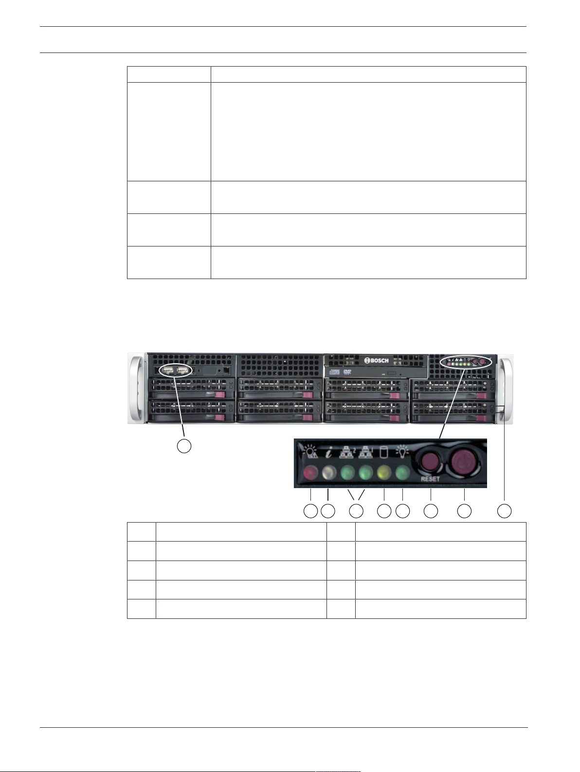
3.2 Device views
The chassis includes a control panel on the front that features power buttons and status
monitoring LEDs. On the rear there are various I/O ports as well as power supply modules.
Front view:
The chassis includes 7 low profile expansion slots.
your rack, follow the instructions included in this manual.
indicate system status and buttons control system power.
2021.03 | V2 | DOC
1 2 USB2.0 ports 2 Power failure LED
3 Information LED 4 NIC1 and NIC2 LEDs
5 HDD (drive activity) LED 6 Power LED
7 Reset button 8 Power button
9 Hard drive carrier LEDs
Installation manual
Bosch Security Systems B.V.
DIVAR IP all-in-one 7000 2U System overview | en 15
1
5
92 63 74
8
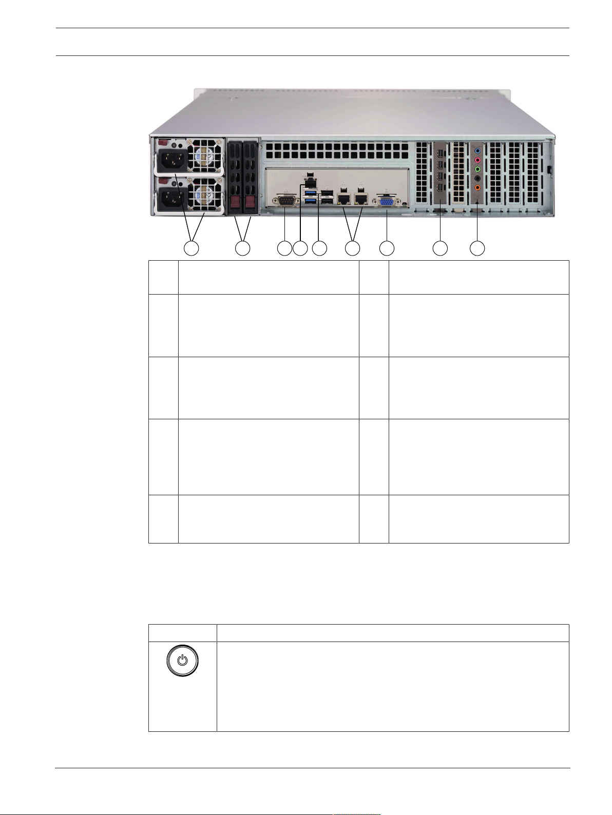
Rear view:
1 2 power supply modules 2 2 redundant SSD drives for operating
system (RAID1 mirror)
3 1 serial port 4 1 network port for BMC (Baseboard
Management Controller) connection
and IPMI (Intelligent Platform
Management Interface) monitoring
5 4 USB ports 6 2 LAN ports for data transmission
7 VGA display output (do not use, if
separate graphics card has been
added to the system)
9 Sound card (audio inputs and outputs)
Note: Available as optional accessory
item, not included by default.
3.3 Control panel elements
The control panel located on the front of the chassis features power buttons and status
monitoring LEDs.
Control panel buttons
Button Description
The power button is used to apply or remove power from the power supply to
the system.
Power
Note: Turning off system power with this button removes the main power,
but keeps standby power supplied to the system.
To remove all power, unplug the system before performing maintenance
tasks.
(teamed)
Note: Do not change the teaming
mode!
8 Graphics card (4 Mini DisplayPort
ports)
Note: Provides digital signal. An active
adapter is required to connect analog
monitors.
Bosch Security Systems B.V.
Installation manual
2021.03 | V2 | DOC
16 en | System overview DIVAR IP all-in-one 7000 2U
Button Description
The reset button is used to reboot the system.
Reset
Control panel LEDs
The control panel LEDs provide status information about the system.
LED Description
This LED indicates that a power supply module has failed.
Power failure
This LED indicates the system status.
System status Description
Information
NIC2
NIC1
Continuously on and red An overheat condition has occurred. (This
may be caused by cable congestion.)
Blinking red (1Hz) Fan failure: check for an inoperative fan.
Blinking red (0.25Hz) Power failure: check for an inoperative
power supply.
Solid blue Local UID has been activated. Use this
function to locate the unit in a rack
environment.
Blinking blue (300msec) Remote UID has been activated. Use this
function to locate the unit from a remote
location.
This LED indicates network activity on GLAN2 when flashing.
This LED indicates network activity on GLAN1 when flashing.
2021.03 | V2 | DOC
HDD
Power
This LED indicates activity on the HDDs or peripheral drives when flashing.
This LED indicates that power is being supplied to the system's power supply
units.
This LED should normally be illuminated when the system is operating.
Installation manual
Bosch Security Systems B.V.
 Loading...