

Page 1
Bosch diesel injection pump rebuild
Rebuilding a Bosch diesel injection pump
Select Language
Select Language
Powered by
Translate
EXIT • Page bottom • Photoessay originally by bricofoy • Also see Injection • Also see
Resealing a Bosch Injection Pump • Downloadable PDF: Bosch VE Pumps.pdf • Reference: Compact
Automotive Diesels
Yes dieselheads, welcome to my friday evening activity: resealing a beautiful Bosch VE injection pump.
Note: This article does not explain how to replace the shaft bearing or how to set internal pressure. It is
only a cleanup and resealing guide.
The pump is in unknown condition, so let's go for a good rebuild with disassembly, cleaning, and complete
replacement of all seals. And its just as well, it was full of crud on the inside.
1
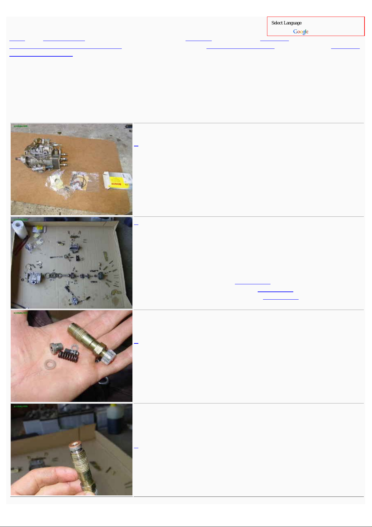
Here you see the starting point, a pump, seals kit with the control
lever seal and driveshaft seal.
As usual, all components must be clean with strict cleanliness
maintained throughout. Moreover, a good lubrication of parts that
push, contact, or slide is essential during the reassembly.
2
We should not complain, a rotary pump is worse! Here it is about an
hour later.
I did not take pictures of the disassembly, go in reverse from what
follows if you have doubts for disassembly. Important settings to
record:
1. Full load adjusting screw
2. Speed control lever graduations
3. Governor shaft adjustment screw
• See here .
• See here .
• See here .
3
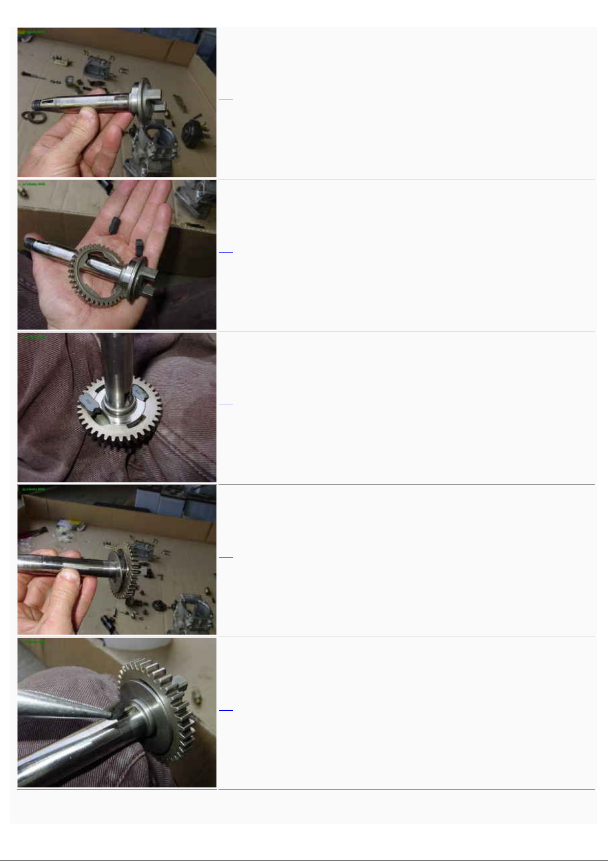
Get started by doing the distributor head hydraulics, it will always
be so de facto. Below are the different components of the delivery
valve holder. bushing, spring, shim, needle, and new sealing
washer.
4
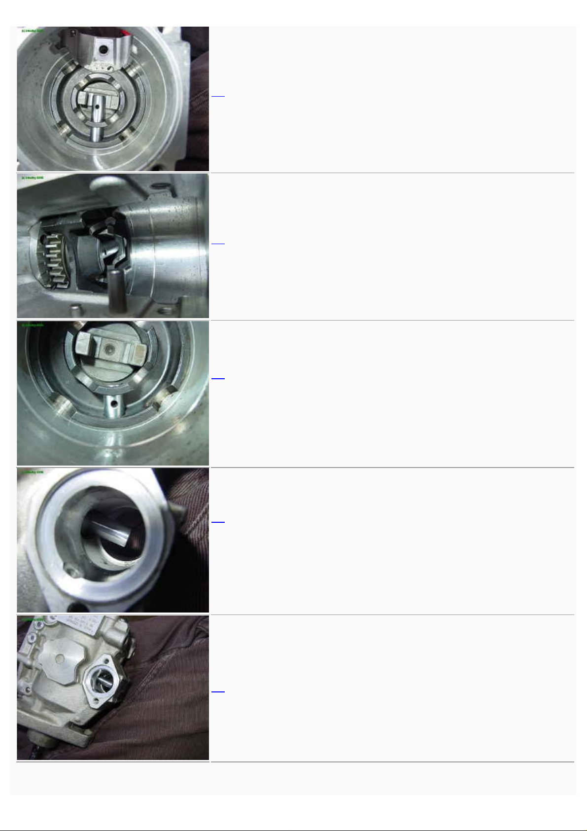
The copper sealing washer on the delivery valve holder.
http://gnarlodious.com/Vanagon/Bosch_Pump/-Rebuild[14-4-2015 0:54:51]
Page 2

Bosch diesel injection pump rebuild
5
The finished distributor head.
That is done, so it is time to get to the serious mechanicals.
6
Woohoo, its competely disassembled! We see even my jeans clear
through the bore.
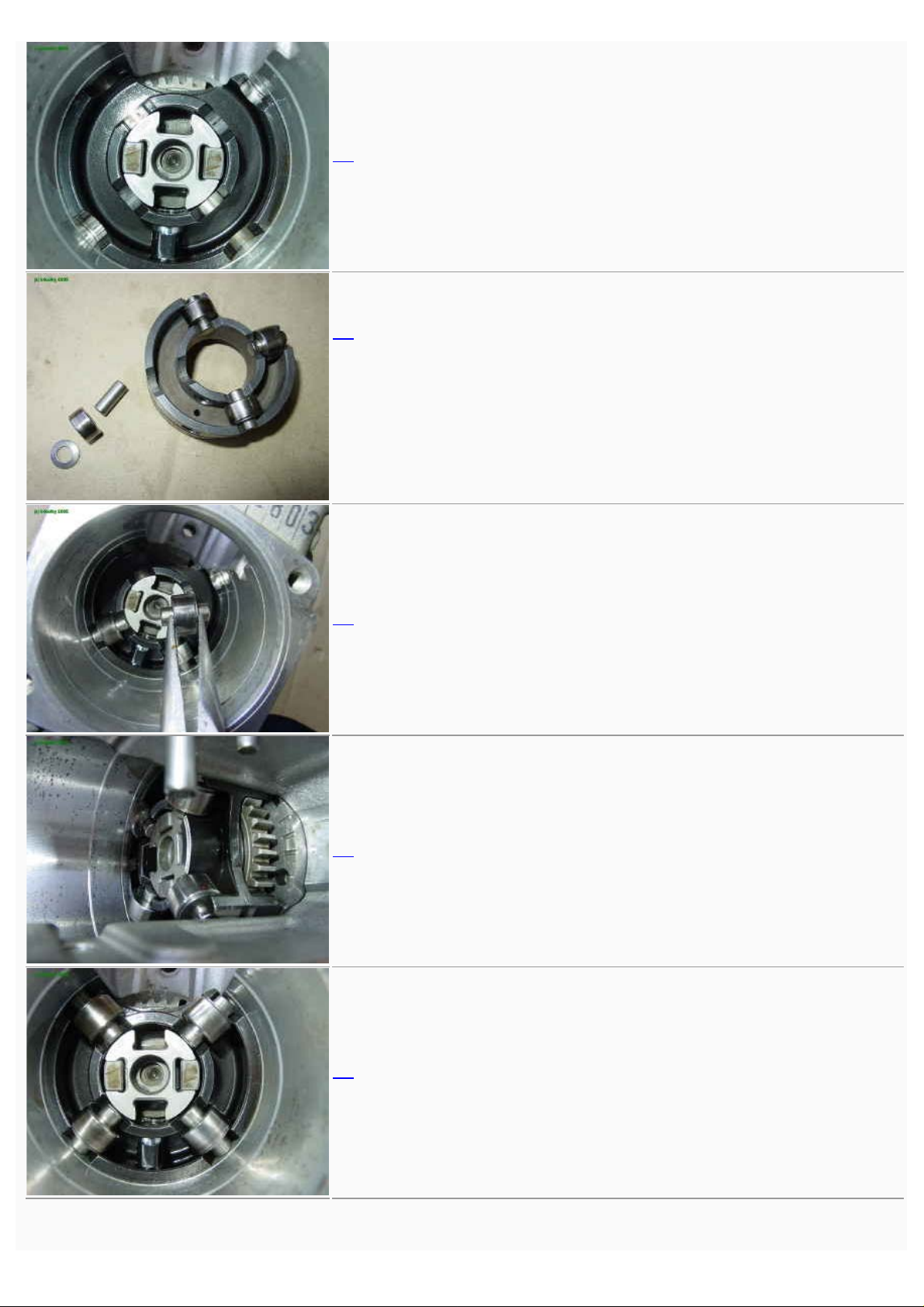
7
Starting with the fuel feed pump, insert the stator ring.
8
Align 180° holes with the the pump housing taps (circled).
9
Then the rotor and vanes.
http://gnarlodious.com/Vanagon/Bosch_Pump/-Rebuild[14-4-2015 0:54:51]
Page 3

Bosch diesel injection pump rebuild
10
First, the rotor.
11
then the vanes using a needlenose plier.
12
13
then the pressure plate.
14
and tightened down.
http://gnarlodious.com/Vanagon/Bosch_Pump/-Rebuild[14-4-2015 0:54:51]
Page 4
Bosch diesel injection pump rebuild
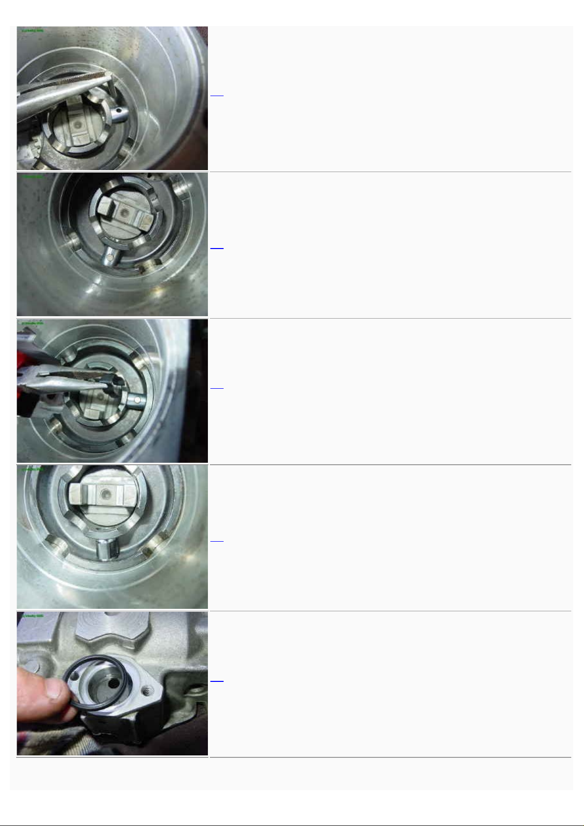
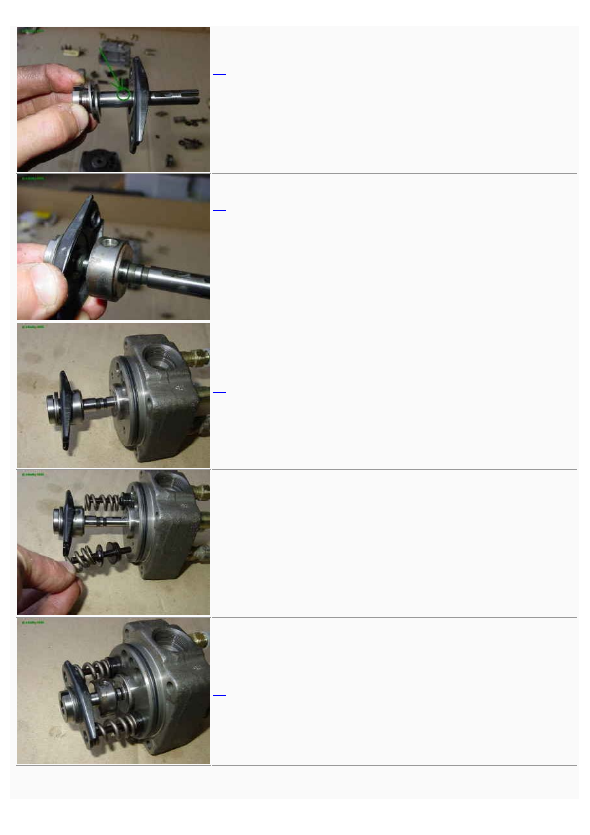
15
Assemble the driveshaft.
16
with the governor drive gear.
17
and two rubber dampers.
18
then the thrust plate.
19
and the woodruff key that drives the fuel feed pump.
http://gnarlodious.com/Vanagon/Bosch_Pump/-Rebuild[14-4-2015 0:54:51]
Page 5

Bosch diesel injection pump rebuild
20
Insert the shaft in the pump housing.
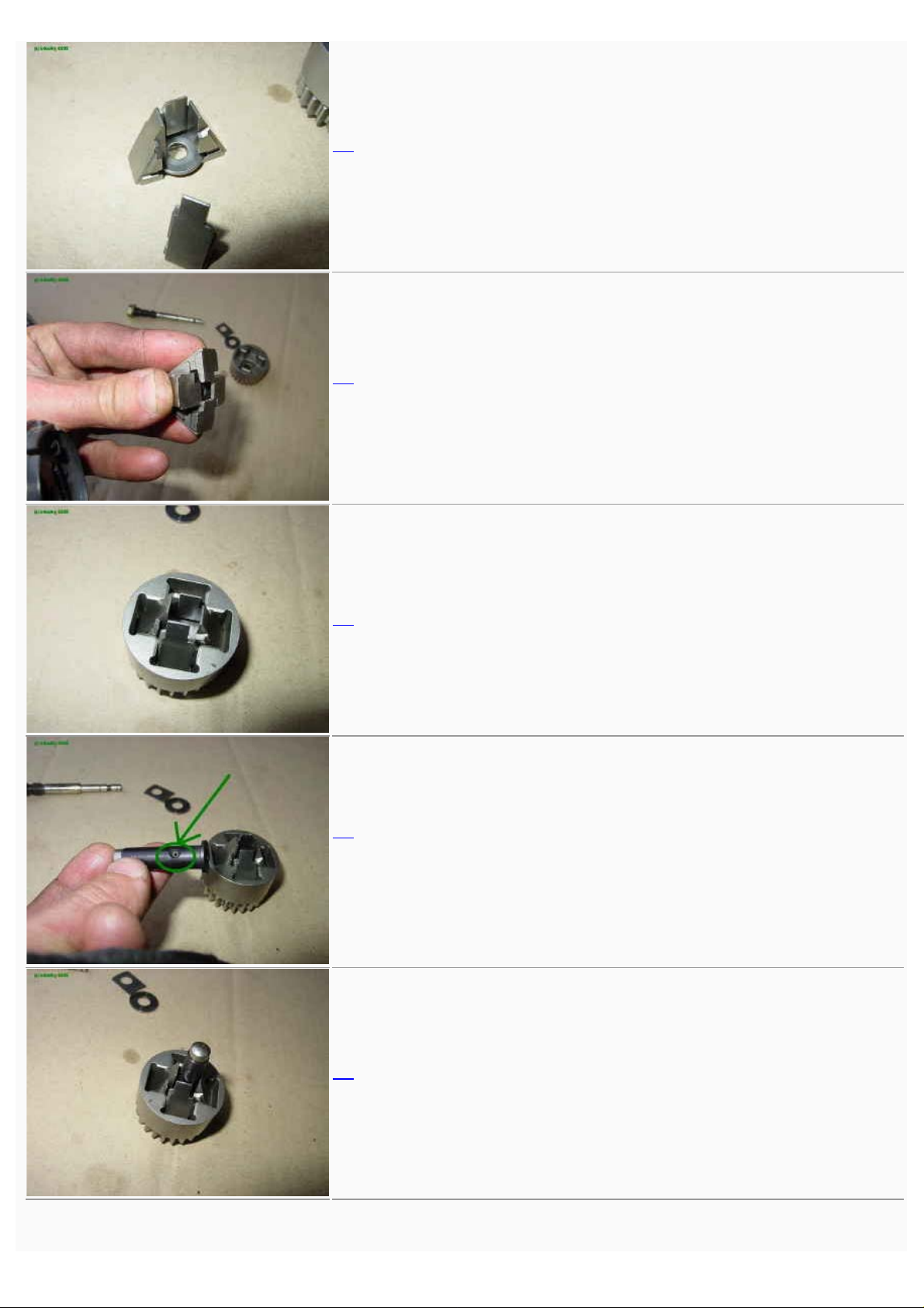
21
Here is the axial view.
22
In this radial view, you can see the lozenge shaped hole for the
timing control.
23
Moving on to the next piece, the roller cage and timing pin.
24
The correct alignment for the timing pin.
http://gnarlodious.com/Vanagon/Bosch_Pump/-Rebuild[14-4-2015 0:54:51]
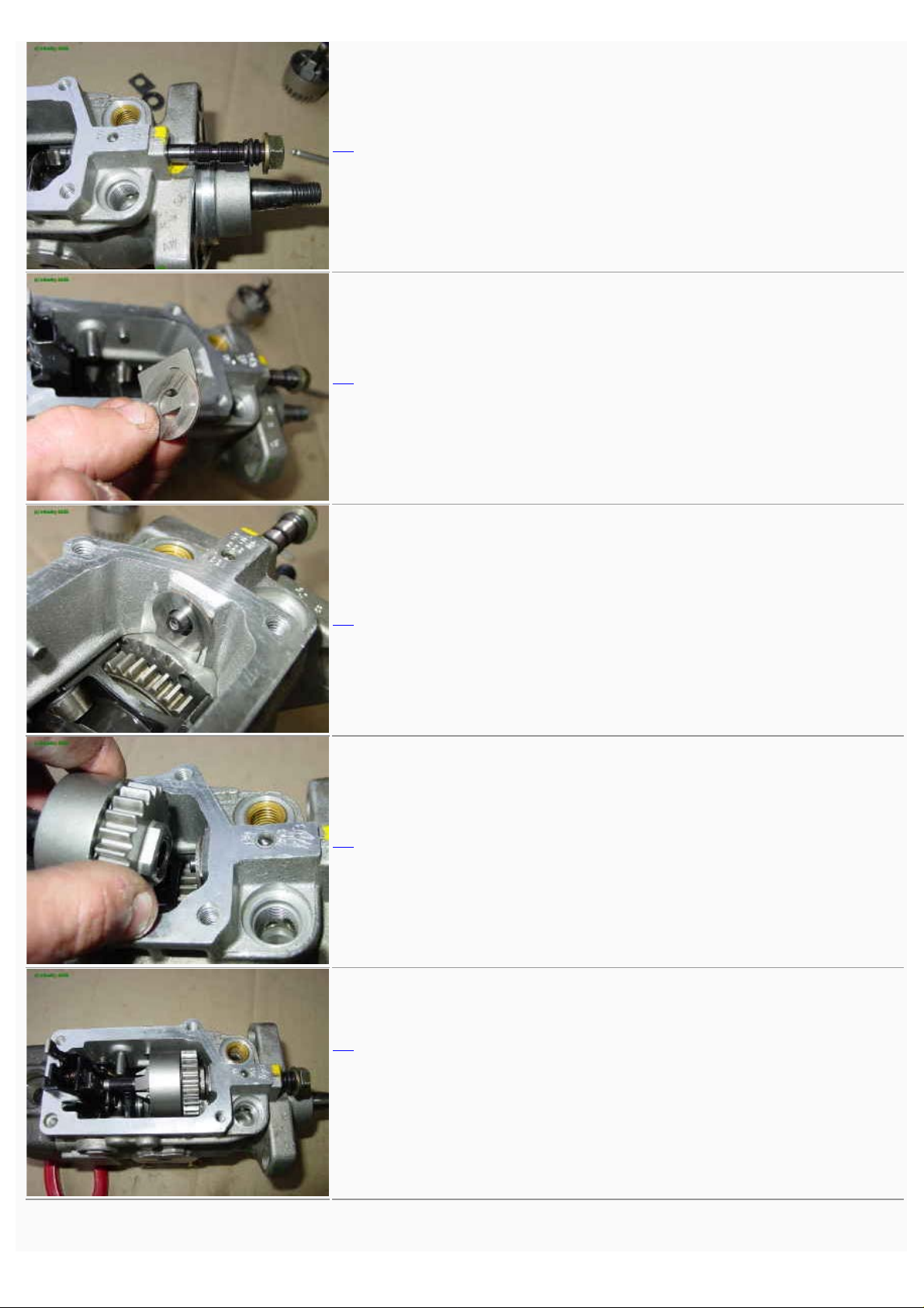
Page 6
Bosch diesel injection pump rebuild
25
An axial view of the cage positioned in the pump housing.
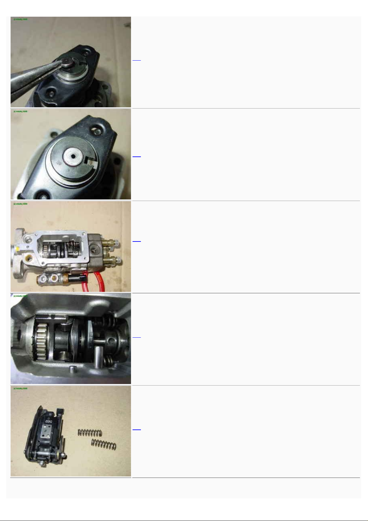
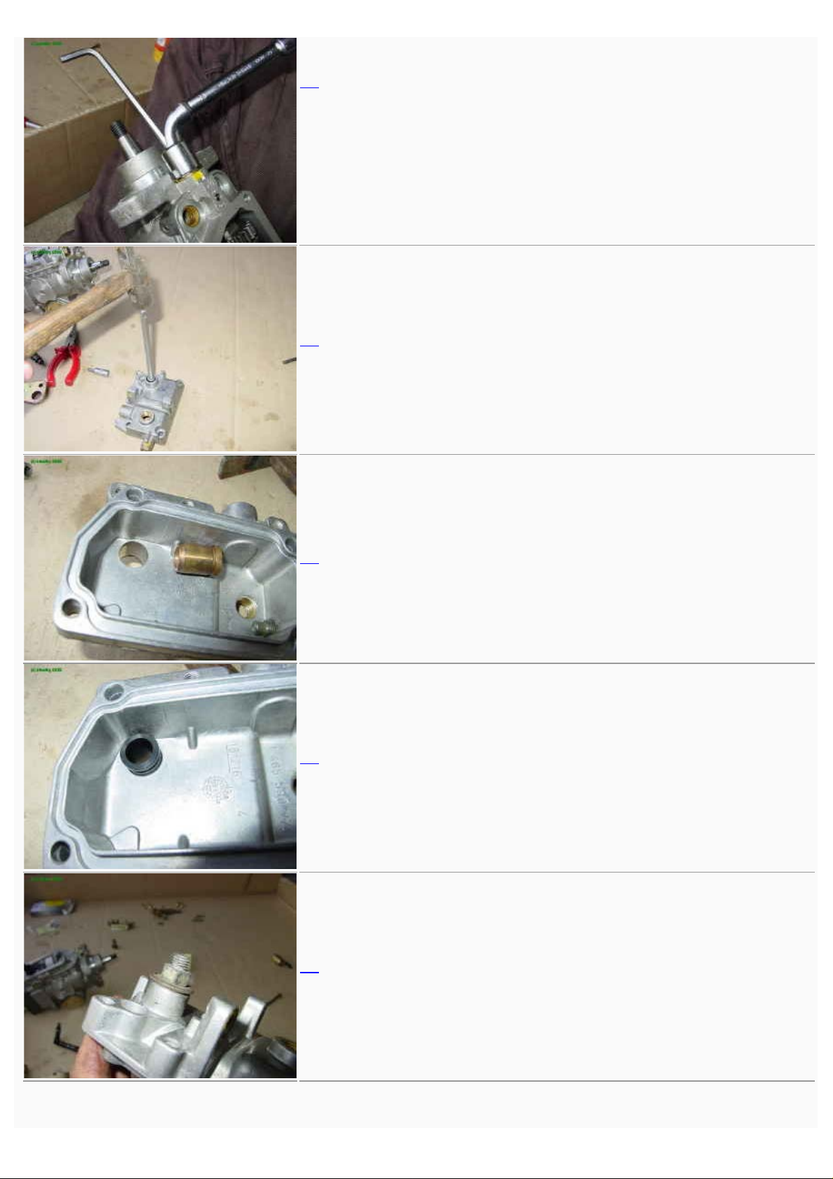
26
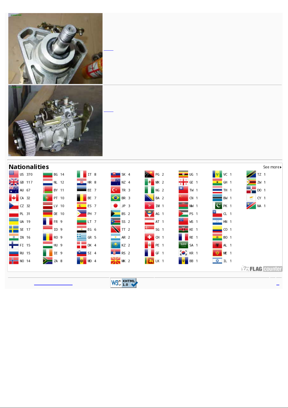
Seen from the top.
27
To understand how these systems interact, slide the timing pin into
the crossover chamber so it protrudes into the timing cylinder. The
pin controls the angular advance of the roller cage.
28
Now slide the actuator back out to install the timing piston.
This is the final position of the actuator.
29
http://gnarlodious.com/Vanagon/Bosch_Pump/-Rebuild[14-4-2015 0:54:51]
Page 7

Bosch diesel injection pump rebuild
30
Now we assemble the timing control piston and pivot.
31
This piston slides back and forth in the cylinder, causing the timing
pin to pivot the roller cage into advanced position.
32
The piston is subject to two forces during normal running. On the
spring side, fuel pump inlet pressure pushes it and the chamber
side, the fuel pressure inside the pump housing pushes it the other
way. The balance of these two pressures set the timing advance.
When the inside ousing pressure is high, the timing is at maximum
advance.
The open end of the piston will clear the fuel pump inlet gallery.
33
Insert the piston in the cylinder.
34
Now push the pin down the lozenge hole.
http://gnarlodious.com/Vanagon/Bosch_Pump/-Rebuild[14-4-2015 0:54:51]
Page 8
Bosch diesel injection pump rebuild
35
and lock with the pin.
36
37
Clip the pin with the retainer.
38
39
Cover the cylinder with the new seal.
http://gnarlodious.com/Vanagon/Bosch_Pump/-Rebuild[14-4-2015 0:54:51]
Page 9

Bosch diesel injection pump rebuild
40
With the cover screwed on.
41
Then on the other side, the timer spring and coldstart advance.
42
43
There are no controls for electrical coldstart on this car, so I put the
usual cover on the cylinder.
44
Insert the cross coupling that drives the rest of the pump.
http://gnarlodious.com/Vanagon/Bosch_Pump/-Rebuild[14-4-2015 0:54:51]
Page 10
Bosch diesel injection pump rebuild
45
46
Then the rollers. They are shown here in their cage outside the
pump.
Note the orientation of the washers, which are shaped to the inside
curvature of the outer flange.
47
48
49
Axial view of the rollers installed.
http://gnarlodious.com/Vanagon/Bosch_Pump/-Rebuild[14-4-2015 0:54:51]
Page 11

Bosch diesel injection pump rebuild
50
Insert the spring in the center.
51
The spring in position.
52
Put the cam disk in, completing the roller cage.
Timing is adjusted by the slight rotation of the roller cage relative to
the camplate.
53
Note that the plunger drive pin (circled) aligns with the woodruff key
of the driveshaft.
54
The cam lobes rolling on the cage cause the plunger to reciprocate
and rotate simultaneously, building the high pressure for injection.
http://gnarlodious.com/Vanagon/Bosch_Pump/-Rebuild[14-4-2015 0:54:51]
Page 12
Bosch diesel injection pump rebuild
55
Moving now to the distributor plunger.
The spill port (circled) regulates the volume of injected fuel. When
the port is open, pressure drops and injecting stops.
56
The control collar (below), driven by the governor, adjusts the
timing of the spill port.
When injecting, the plunger is pushed by the cam. Depending on the
position of the governor, the spill port is opened by the plunger
stroke. That is the control mechanism of the fuel injection.
57
Insert the distributor plunger in the distributor head.
58
Then the return springs.
59
http://gnarlodious.com/Vanagon/Bosch_Pump/-Rebuild[14-4-2015 0:54:51]
Page 13
Bosch diesel injection pump rebuild
60
The spacer of the plunger end.
61
62
Insert the entire distributor head assembly into the pump, but don't
tighten it down just yet.
63
The radial view.
64
We will now go the governor tension lever and support springs.
http://gnarlodious.com/Vanagon/Bosch_Pump/-Rebuild[14-4-2015 0:54:51]
Page 14
Bosch diesel injection pump rebuild
65
Support springs go in these holes. This part can be a bit of a
challenge getting the springs positioned.
66
67
The tension lever pivots on three sided bolt -hinges. I modified an
old 13mm socket to fit the triangular bolts.
68
Insertion of these bolts with new aluminum washers.
69
Now we are installing the lever assembly from the top.
http://gnarlodious.com/Vanagon/Bosch_Pump/-Rebuild[14-4-2015 0:54:51]
Page 15

Bosch diesel injection pump rebuild
70
To do this, remove the distributor head (which you did not bolt
down) and position the lever assembly so it looks like this.
Notice on the plunger shaft the spill port (green), the distributing slit
(red), and four intake slits (green) extending into the high pressure
chamber. The plunger is galleried to facilitate all this.
71
The hydraulic manifold ready to assemble with the return springs.
72
Now we are ready to install the head assembly and screw it in. This
may be a bit of a challenge since the springs tend to fall out, so
have some patience here.
73
The top view.
74
Turning now to the centrifugal governor, here are all the parts.
http://gnarlodious.com/Vanagon/Bosch_Pump/-Rebuild[14-4-2015 0:54:51]
Page 16
Bosch diesel injection pump rebuild
75
Assemble the flyweights.
76
Put that assembly into the rotor.
77
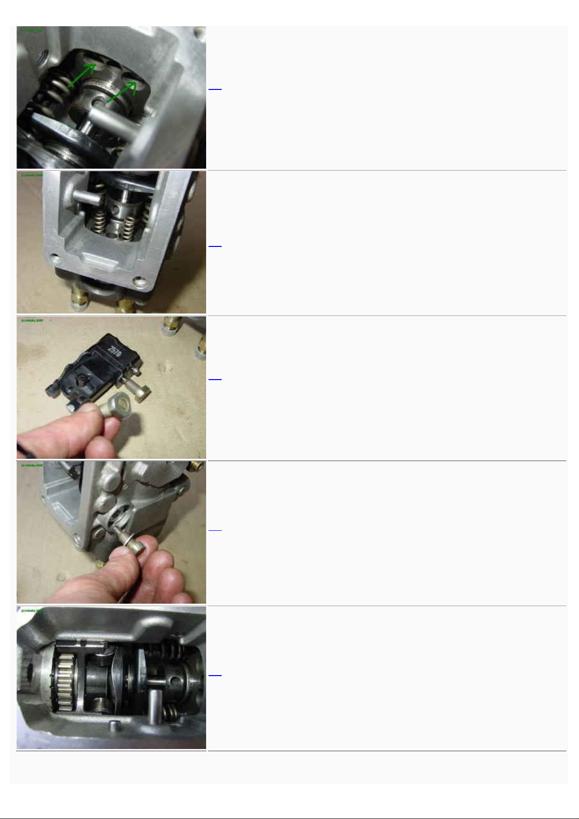
78
Replace the governor sleeve. Note the calibration hole that
modulates initial injection according to load.
79
Insert the shaft through the rotor.
http://gnarlodious.com/Vanagon/Bosch_Pump/-Rebuild[14-4-2015 0:54:51]
Page 17
Bosch diesel injection pump rebuild
80
The governor adjustment screw.
81
Washers between the rotor and housing.
82
83
Install the rotor assembly.
84
The adjustment of this shaft is important, because it modulates
initial injection according to load (along with vacuum, if so
equipped). This is why it is a good idea to mark its position at
disassembly.
http://gnarlodious.com/Vanagon/Bosch_Pump/-Rebuild[14-4-2015 0:54:51]
Page 18
Bosch diesel injection pump rebuild
85
Use a hex key to screw in the shaft to the same position it was
before disassembly. Use two wrenches at the same to tighten the
time jam nut so the shaft is locked.
Now the pump housing is complete, only needing the pump cover
and the fuel pressure regulation valve.
86
On the cover, drive out the old control shaft bushing.
87
88
Insert the new bushing from the inside.
89
Use an old bolt and large washers to clamp the bushing down flush.
http://gnarlodious.com/Vanagon/Bosch_Pump/-Rebuild[14-4-2015 0:54:51]
Page 19

Bosch diesel injection pump rebuild
90
91
Put in the control shaft and yoke.
The yoke assembly holds three springs, the governor spring, the
partial-load spring and the idle damper spring.
92
Close up of the governor linkage. Retract the rod so the flat section
in the rod (green) slips into the narrow slot in the lever (red).
93
Assemble the speed control lever with its return spring and new
seal.
94
Here you see the idle adjusting screw on the top of the picture, and
the maximum speed screw at he bottom.
This is one place where you need to identify the lever's setting at
disassembly. Adjust it to the same graduation.
http://gnarlodious.com/Vanagon/Bosch_Pump/-Rebuild[14-4-2015 0:54:51]
Page 20

Bosch diesel injection pump rebuild
95
The regulating valve sets the proper fuel pressure for the timing
advance and fuel feed for the distributor plunger.
Install it now with new seals.
96
97
The fuel shutoff solenoid.
98
Notice that immediately above the solenoid is the full load adjusting
screw. You may prefer to mark the setting of this screw before
disassembly.
99
Last piece, the driveshaft seal.
http://gnarlodious.com/Vanagon/Bosch_Pump/-Rebuild[14-4-2015 0:54:51]
Page 21
Bosch diesel injection pump rebuild
100
101
You have done it! Not as hard as you thought it would be.
All that is needed now is to mount the pump!
Popup by Joao Rodrigues Script modified: 2015/04/03 • ?
http://gnarlodious.com/Vanagon/Bosch_Pump/-Rebuild[14-4-2015 0:54:51]
 Loading...