

Page 1
Page 2

2
en
page 13–16
fr
page 17– 30
es
página 31 – 44
Page 3
3
몇 WARNING
To reduced the risk of fire, electric shock,
or injury to persons, observe the following:
A. Installation work and electrical wiring
must be done by authorized person(s)
in accordance with all applicable
codes and standards, including firerelated construction.
B. Sufficient air is needed for proper
combustion and exhausting of gases
through the flue (chimney) of fuel burning equipment to prevent backdrafting. Follow the heating equipment
manufacturer’s guideline and safety
standards such as those published by
the National Fired Protection Association (NFPA), and the American Society
for Heating, Refrigeration and Air
Conditioning Engineers (ASHRAE),
and the local code authorities.
C. When cutting or drilling into wall or
ceiling, do not damage electrical
wiring and other hidden utilities.
D. Ducted fans must always be vented
to the outdoors.
E. Always unplug or disconnect the
appliance from the power supply
before servicing.
F. This unit is designed for indoor use
only. Use this unit only in the manner
intended by the manufacturer.
G. Make certain the cooktop is appro-
priate for use with a downdraft vent.
H. Not intended for use with professio-
nal-style cooktops.
몇 WARNING
For general ventilating use only. Do not
use to exhaust hazardous or explosive
materials and vapors.
To reduce risk of fire and to properly
exhaust air, be sure to duct air outside.
Do not vent exhaust air into spaces within walls, ceilings, attics, crawl spaces or
garages.
To reduced the risk of fire, use only metal
duct work.
To reduce the risk of fire, electric shock
and injury to persons, Downdraft must
be used with Internal, Remote or Inline
Blower.
To reduce the risk of fire or electric
shock, do not use the fan with any solidstate speed control device.
This appliance has been found to be in
compliance with UL 507 Standard for
Electric Fans and CAN/CSA-22.2 No.
113 Canadian Standard for Fans and
Ventilators. It is the responsibility of the
owner and the installer to determine if
additional requirements or standard apply in specific installation.
몇
SAFETY INSTRUCTIONS
READ ALL INSTRUCTIONS BEFORE USING THE APPLIANCE.
READ AND SAVE THESE INSTRUCTIONS
Page 4

4
Parts Needed (standard)
G Tape Measure
G Phillips Head Screwdriver
G Aluminum Duct Tape
G Ductwork (configuration varies depen-
ding on location; See pages 7-12 for further information)
G Additional Sheetmetal screws (as neces-
sary for ductwork installation)
G Saw (or equivalent for cutting counter-
top)
G #8 x 1 1/4” Wood Screws (4)
G Plumb Bob
G Wire to reach Remote or Inline Blower
Parts Needed (special)
G Special Blower
G Transition Box (for use only with Inline
and Remote Blowers)
G Recirculation Module (used only for recir-
culation applications)
Note: Downdrafts work with these blowers: 600 CFM Integrated, Remote or Inline
Blowers 1000 CFM Remote or Inline Blowers
Parts Supplied
G Downdraft assembly (1)
G #8 Sheetmetal Screws (8)
G Blower Cord Strain Relief (1)
G Hardware for brackets on vent (2)
G Remote Blower Pigtail
Page 5
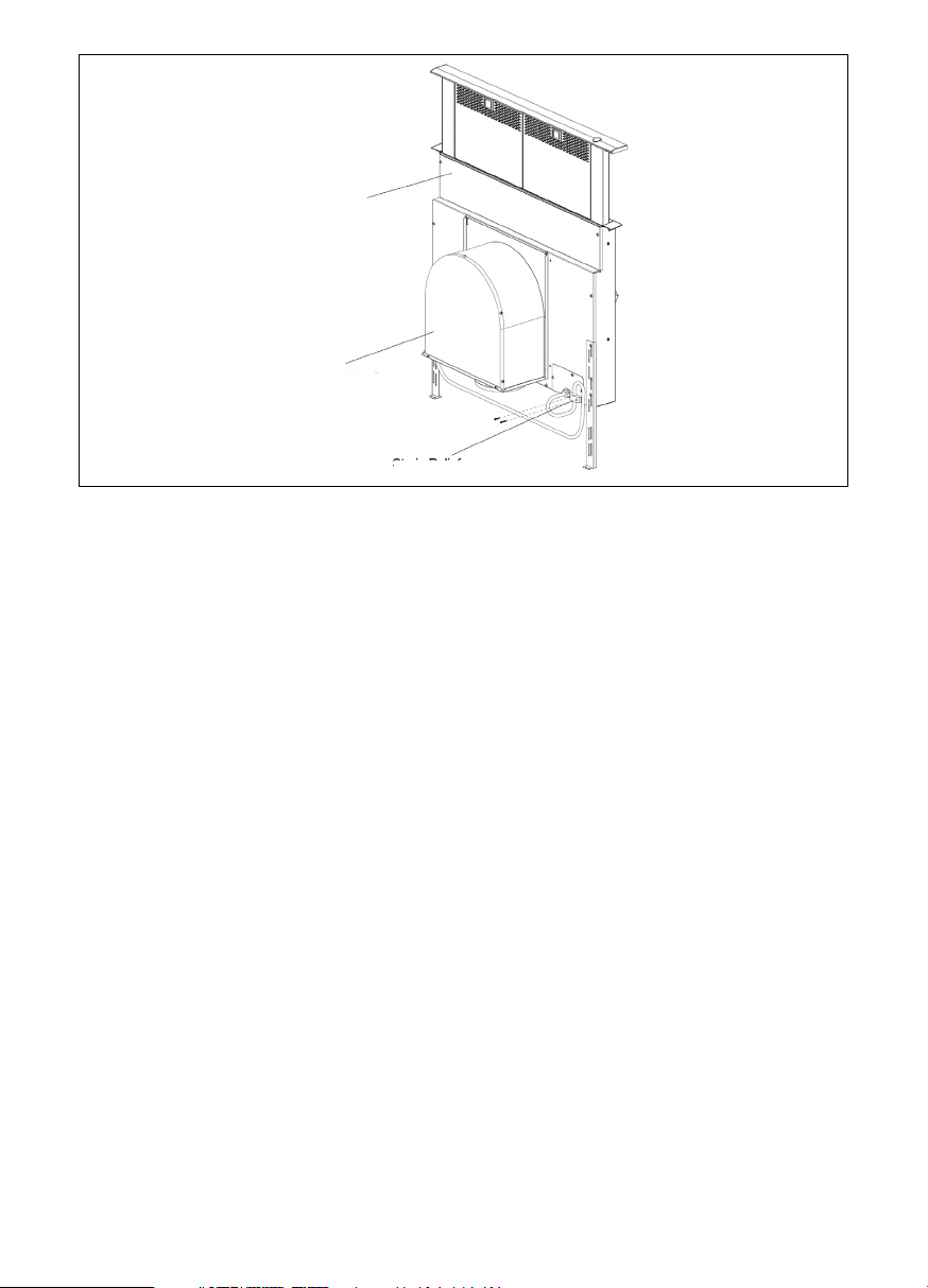
INTRODUCTION
GENERAL DESCRIPTION
The complete downdraft system consists of
the downdraft, a blower and a transition
box if using an Inline or Remote Blower. A
recirculation module is also available when
ducting to the outside is not preferred or
not possible. (See Fig. 1).
The blower can be either integral (mounted
on the vent intake in the cabinet under the
cooktop), an inline (mounted between the
kitchen and exterior wall anywhere within
the duct line), or a remote (mounted on the
roof or outside wall). When a remote or inline blower is used, a duct transition is
mounted on the ventilator intake in place of
the integral blower to connect the intake to
the duct work. The duct transition must be
purchased separately.
The integral blower or duct transition can
be mounted in different positions on the
intake to route ductwork to avoid cabinet,
building framing, utilities, etc.
The downdraft system is available in 30inch or 36- inch. Intended for non-professional style cooktops only.
A Recirculation Kit can be purchased separately and used in conjunction with the Integral Blower if ducting to the outside is not a
viable option.
Step 1: Plan the installation
Carefully follow the planning procedures
listed below (See Figure 2). Sketches are
NOT intended to be a replacement for
careful planning.
A. Determine whether a remote, inline, or
integral blower will be used. Remote
and inline blower installation requires
4 wires plus a ground wire to run from
the downdraft to the blower.
B. Make sure that adequate cabinet and
counter space has been provided and
that the intake and blower will be accessible if service is required.
C. Consider that cross drafts created by
adjacent open windows, doors, air conditioning, old heating vents, recessed
ceiling lights, and traffic patterns may
affect performance.
D. For gas cooktop installations make sure
that a minimum 10 square inch opening
is provided in the toe-kick or other cabinet area. Inadequate ventilation of the
cabinet below the cooktop may result in
flame outage when operating the vent
system.
E. Provide for air supply or ”make-up
air” to the room where unit will be
installed. If ”make-up air” is not provided, then problems, such as fireplace
chimney downdrafts, could result.
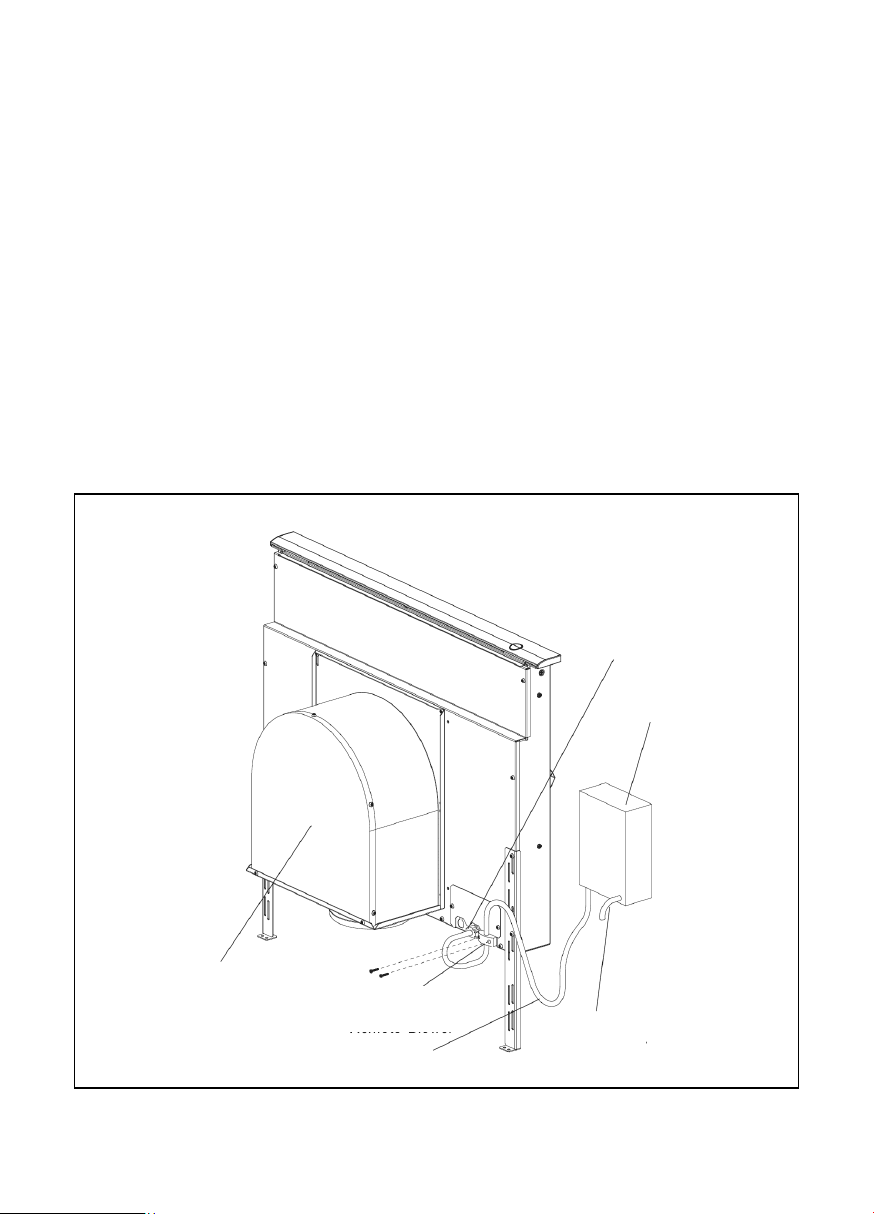
Fig. 1
5
Downdraft - Unit
Strain Relief
Blower /
Duct Transition Box
(Not Included)
Page 6
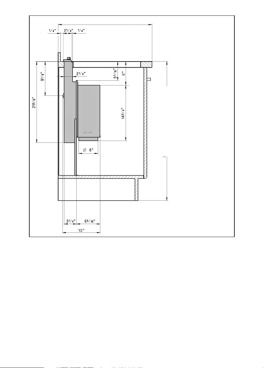
Fig. 2
F. Investigate potential ductwork routes
and choose the shortest possible route
from the unit to an outside wall or to the
roof via an inside wall and attic. For guidance, typical ducting installations are
shown in figures 3 through 6. Installation
in island locations will require under floor
ducting. Peninsula locations usually
require ducting laterally through cabinets
or under cabinet toe spaces. Consider
potential interferences to ductwork from
building framing (floor joists, wall studs,
etc.) and utilities (electrical wiring, water,
gas, or sewer lines, etc).
G. Purchase the necessary ductwork as
needed to duct to the outside or purchase separately the downdraft Recirculation Module if ducting to the outside is not
a viable option.
• Be certain to avoid interference with gas and electric supply to cooktop.
• Shelving and drawer depths
are dependent upon cooktop depth and setback.
6
Dimension depends on Countertop
min.
Vent
Blower /
Duct Transition Box
Dimension depends on Cabinet
Page 7
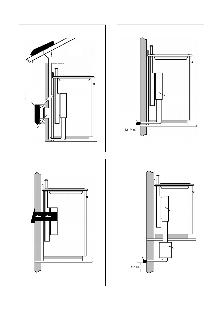
Figures 3 through 6 are examples of possible ducting
Fig. 3
Remote Blower
Roof Mount Installation
Through wall installation
Fig. 4
Integral Blower
Through Wall Installation
Fig. 5
Integral Blower
Through Wall Installation
Fig. 6
Inline Blower
Through Wall Installations
7
Remote
Blower
Remote
Blower
Duct
Transition
Box
Collar
Ground
Wall Cap
Duct
Transition
Box
Wall Cap
Ground
Inline
Blower
Integral Blower
BLOWER ROTATED 90° FOR SIDE
CONNECTION
Integral Blower
Page 8

DUCTWORK INSTALLATION GUIDELINES
G Ducting should vent directly outdoors
(not into an attic, underneath the house,
into the garage or into any enclosed
space). A Recirculation Module is available when ducting to the outside is not
possible.
G Keep duct runs as short and straight as
possible.
G Duct fittings (elbows and transitions)
reduce air flow efficiency.
G Back to back elbows and ”S” turns give
very poor delivery and are not recommended.
G A short straight length of duct at the inlet
of the remote blower gives the best delivery.
G Transition to duct from the integral blo-
wer or remote duct transition as close to
the downdraft as is possible. In order of
preference, use
1st. 10” round duct
2nd. 8” round duct
3rd. 3-1/4” x 14” duct
4th. 7” round duct
5th. 3 -1/4” x 10” duct
6th. 6” round duct
G The use of flexible metal round duct
should only be used when no other duct
fitting exists. Limit use to short lengths
and do not crush when making corners.
G Back to back elbows should be avoided.
DUCTWORK INSTALLATION
GUIDELINES
G Where local codes permit, plastic pipe
(PVC-schedule 40 pipe or ABS pipe 7”
or 8” diameter) can be used in areas of
high ground moisture and in slab floors
to eliminate future rusting.
G Use only duct work constructed of mate-
rials that are acceptable by the applicable codes. All duct should be 26 gauge
or heavier to minimize flex due to air
flow.
G The remote blowers require a 10” or 6”
diameter round duct (depending on
model) to match the inlet ring. A transition is necessary from other duct sizes.
G Use sheet metal screws as required to
support the duct weight, and seal all
joints with duct tape.
G Be certain that the duct work does not
interfere with floor joists or wall studs.
G Do not exhaust more than one vent into
a single duct run.
G Cold weather installations should have
an additional backdraft damper installed
to minimize backward cold air flow and a
nonmetallic thermal break to minimize
conduction of outside temperatures as
part of the ductwork. The damper
should be on the cold air side of the
thermal break. The break should be as
close as possible to where the ducting
enters the heated portion of the house.
G Always use an appropriate roof or wall-
cap with damper. Laundry type wall caps
should never be used.
8
Page 9

Step 2: Prepare Countertop Cutout
Refer to the cooktop installation instructions
for dimensions of cooktop, countertop cutout, and cabinet requirements prior to
making any cutouts. Cooktop depth and
countertop back-splash depth can vary
greatly from one to another. These variations may cause the fit of the downdraft and
cooktop to be tight. A countertop (front
edge) with a raised lip and/or a wide backsplash (back edge) may not allow enough flat
countertop for a proper installation.
Y Check that the cooktop is far enough
forward that the downdraft will fit behind
it. Verify all dimensions prior to cutting
the countertops.
Use the physical products to confirm
cutouts whenever possible.
For all installations verify that all cutouts will
clear the inside of the front countertop support rail, and that the cooktop and vent will
be centered left to right within the cutout.
Also, make certain that the front
and rear cutouts are straight and parallel to
the front edge of countertop and the rear
backsplash and/or wall. Assure that the
side cutouts are square to the front and rear
cutouts.
All illustrations and dimensions are based
on standard 24” deep by 36” high American
style base cabinets with 25” countertops.
When installing laminated or solid surface
countertops such as Surell™ and Corian
®
,
be sure to follow the countertop manufacturer’s instructions regarding minimum
comer radii, reinforcement of corners, etc.
Note: Check boxes as tasks are completed.
For overhead cabinet and cooktop side
clearances consult cooktop Installation
Instructions.
9
Page 10
10
Notes
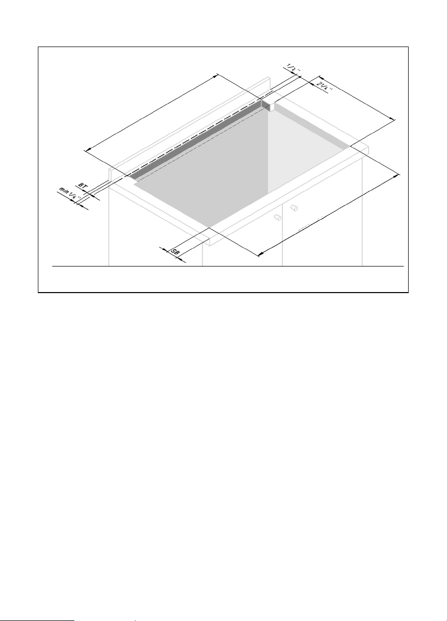
Dimension ”SB” is the minimum distance from the leading edge of the counter to the leading
edge of the cutout.
Dimension ”BT” is the thickness of backsplash that provides 1/4” clearance between vent
and backsplash. Any backsplash with a curved radius where it meets the counter will require
additional clearance. Thicker backsplashes may be used by increasing the counter and cabinet depths.
Set the cooktop into the countertop opening so that the back edge of the cooktop overlaps
the leading edge of the downdraft.
Fig. 7
INSTALLATION WITH COOKTOPS
Wide 31”: 28
3
/
8
”
Wide 37”: 34
3
/
8
”
Cutout and Overall Dimensions
Cutout and Overall Dimensions
Page 11
11
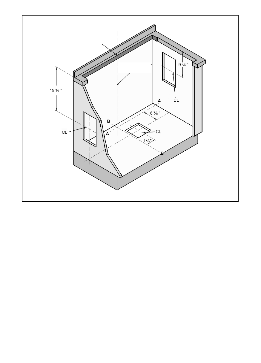
Fig. 8
Step 3: Prepare Duct Cutouts in
Cabinet
Y A. Refer to Figure 8. Drop a plumb-line
from Point ”P” at the rear center of the
countertop cutout. Mark this point on the
bottom of the cabinet below. Construct
two reference lines through this point:
one should be parallel to the cabinet
front and directly below the rear countertop cutout (Line A-A), and the other (Line
B-B) should be at right angles to A-A.
Y B. Using these reference lines as a base
for the measurements, layout the necessary cabinet cutouts needed to implement the planned ductwork route. Where
a range of measurements is noted,
choose a measurement that allows best
clearance from wall studs, floor joists,
utilities, or other obstructions.
Step 3: Prepare Duct Cutouts in
Step 3: Cabinet
Y C. Before cutting for ducting, temporarily
set intake and cooktop in place and
attach integral blower (or duct transition
fitting if a remote or inline blower is installed). Refer to steps 6 and 7. Verify that
the duct cutouts as marked will match
the hardware installation. Adjust the duct
cutout as necessary to match hardware
installation.
Y D. Remove temporarily placed hardware
and make cutouts in cabinet to accommodate ductwork installation.
Y E. Make all other cabinet modifications
needed to provide proper clearances for
drawers or removable shelving.
Note: Check boxes as tasks are completed.
Center Line (CL)/
Plumline
Point "P"
Page 12

Step 4: Install Ductwork (Remote or
Inline Blower, If Used)
Y A. Install the ductwork and remote blo-
wer (if used) in accordance with the ductwork routing plan developed in Step 1.
Y B. Make sure that the installation com-
plies with all installations guidelines. Type
and length of ducting and lack of makeup air may reduce CFM. Also check that
the opening where duct passes through
outside wall or roof has been properly
flashed and sealed to prevent leakage.
Y C. If using Integral Blower, proceed to
Step 5.
Y D. If using Remote or Inline Blower, refer
to Installation Instructions with that
model.
Step 5: Install Electrical Service
Y Check your local building codes for pro-
per method of installation. In the U.S., if
there are no applicable local codes, this
unit should be installed in accordance
with the National Electric Code
ANSI/NFPA No. 70, Current Issue. (In
Canada, installation must be in accordance with the CAN 1-B149.1 and .2Installation Codes for Gas Burning Appliances and/or local codes).
Y The appliance must be grounded. In the
event of an electrical short circuit, grounding reduces the risk of electric shock by
providing an escape wire for the electric
current. This appliance is equipped with
a cord having a grounding wire with a
grounding plug. The plug must be plugged into an outlet that is properly installed and grounded.
몇 WARNING – Improper grounding can
result in a risk of electric shock.
Only a qualified electrician, or similarly quali-
fied persons, should make the electrical
connections.
Do not use an extension cord. If the power
supply cord is too short, have a qualified
electrician install an outlet near the appliance.
The receptacle should be located under
the countertop so that the 30 inch long
power cord from the vent will reach it.
See Figure 8.
Y The cord should be routed beneath the
appliance and away from heat generated
by the cooktop. Access should not be
obstructed by blower, cabinet work,
ductwork or electrical/gas utilities for the
cooktop. All power for the vent system
(including the remote blower, if used) is
supplied via the cord to the intake unit.
The outlet can usually be extended from
another kitchen outlet or have its own
circuit from the main service panel.
Do not plug vent cord into receptacle
until Step 8.
Step 6: Mount Vent and Cooktop
Y A. Remove grease filters and any
packing materials from inside the intake.
Y B. Set the vent intake into rear of coun-
tertop opening. Carefully lower it into
position so that the flanges on the rear
sides and edges fully support the unit
hanging from the countertop.
Y C. Hold the unit against the rear of the
countertop opening, and slide the leg
brackets down to meet the bottom of
cabinet. Check and adjust for plumb,
then fasten leg brackets to cabinet with
hardware provided.
Note: Check boxes as tasks are completed.
12
Page 13
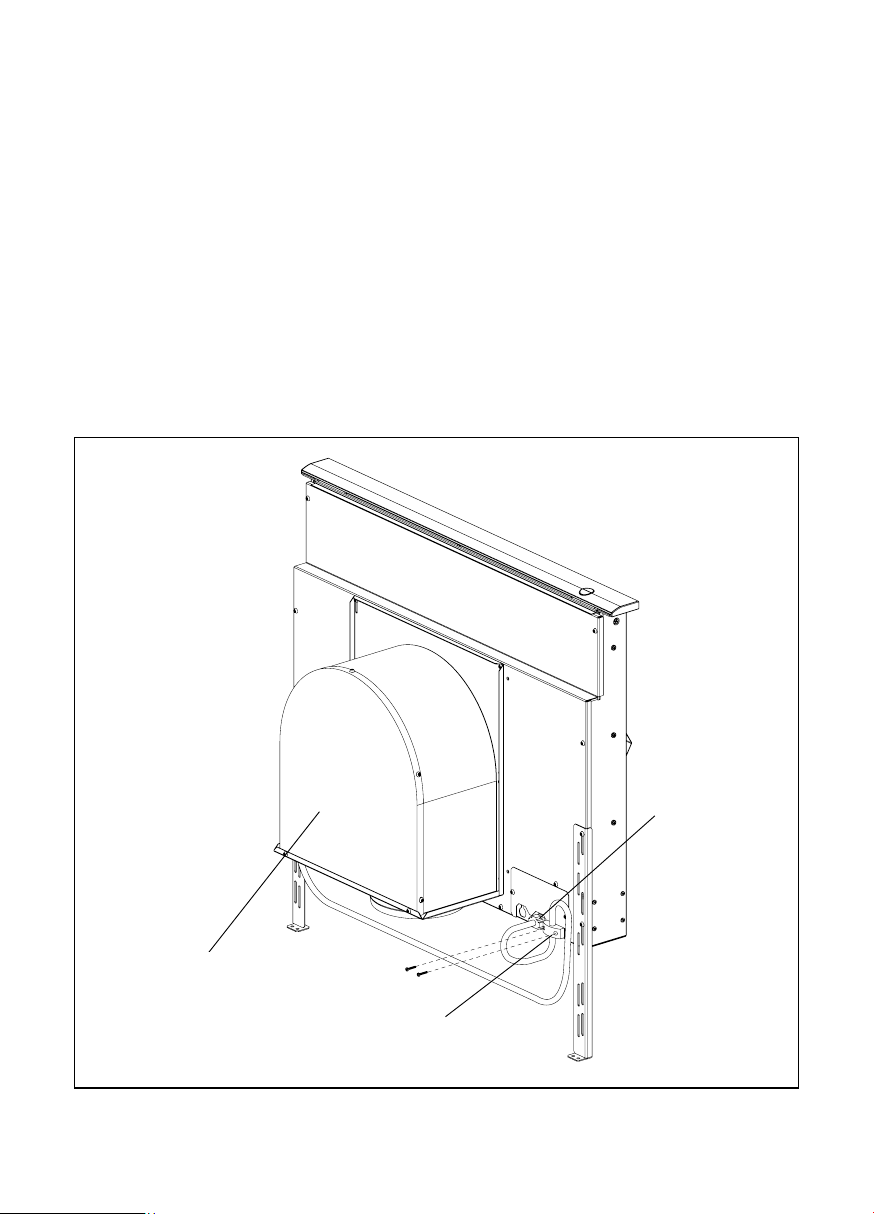
Step 7: Mount Integral Blower or
Outlet Duct Transition for Remote or
Inline Blower
Integral Blower (see Figures 9 and 11 for
further detail):
Y A. Attach blower in front of round
exhaust outlet with 4-6 (depending on
configuration) #8 sheetmetal screws.
Y B. Feed cord from blower through strain
relief.
Y C. Secure strain relief with screws.
Y D. Attach strain relief to downdraft near
junction box.
Y E. Connect cord to downdraft at 6 pin
connector.
Y F. Connect blower to ductwork.
Fig. 9 – Internal Blower
13
Step 7: Mount Integral Blower or
Outlet Duct Transition for Remote
Blower
Integral Blower VTN600CV2C (see Figures
10 and 12 for further detail):
Y G. Place the cooktop in countertop ope-
ning with the rear edge of cooktop overlapping the front edge of the vent. Make
sure rear edge of cooktop does not bind
against front of snorkel. Follow the
manufacturer’s installation Instructions
for installing gasket strips, protective
heat tape (if required), securing the cooktop to the countertop and making the
cooktop electrical and/or gas connections.
Note: Check boxes as tasks are completed.
Internal Blower
Strain Relief
6 Pin
Connector
<*^"P) 6^"
G*"P)F^^
')D
^W*"
Page 14
Remote or Inline Blower (see Figures 10
and 11 for further detail):
Y A. Remove junction box cover and
connect conduit with 5 wires from remote
blower. Hook up wires per Wiring.Fig. 10.
Replace junction box cover.
Y B. Attach Duct Transition Box at moun-
ting holes with sheetmetal screws.
Y C. Feed remote blower pigtail through
strain relief.
Y D. Attach strain relief to downdraft near
junction box.
Y E. Connect pigtail to downdraft at 6 pin
connector.
Y F. Run pigtail wires to junction box.
Y G. Inside junction box, connect conduit
with five wires from remote or inline blower. Use a conduit connector to secure.
Fig. 10 – Remote Blower
14
Integral Blower VTN600CV2C (see Figures
10 and 12 for further detail):
Note: Blower and duct transition box may
be installed with duct outlet left, down or
right. Install blower or duct transition in
such a way that access panels can be
removed for service.
Y H. Place the cooktop in countertop ope-
ning with the rear edge of cooktop overlapping the front edge of the vent. Make
sure rear edge of cooktop does not bind
against front of snorkel.
Follow the manufacturer’s installation
Instructions for installing gasket strips,
protective heat tape (if required), securing the cooktop to the countertop and
making the cooktop electrical and/or gas
connections.
Note: Check boxes as tasks are completed.
Strain Relief
Remote Blower
Pigtail
6 Pin Connector
Junction Box
Duct Transition Box
Conduit To
Remote Blower
Page 15
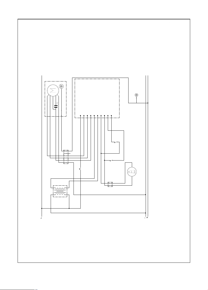
Wiring Diagram
Fig. 11
15
WARNING: POWER MUST BE DISCONNECTED BEFORE SERVICING THIS APPLICANE
SW POSITION
SHOWN WITH
DOWNDRADT IN
LOWERED POSITION
ABBREVIATIONS:
C = COMMON
NO = NORMALLY OPEN
NC = NORMALLY CLOSED
POWER
3 WIRE SINGLE PHASE 60 Hz
L1: 120 V
N: GROUNDED WHITE WIRE
SPEED 1 RED WIRE
SPEED 2 BLUE WIRE
SPEED 3 BROWN WIRE
GND: GROUNDED GREEN WIRE
RATING: 120V-10A
control pc board
brown Speed 3
blue Speed 2
Speed 1
red
white
green/yellow
green/yellow
white
brown
blue
red
+)M<F G<A? D;G)':);9
DBMF
GD)+)FBMA M<F
?Y),:)L
AY FBIA M;<H M<F
FH<AY),: L:
GD),)?I M<F
AY FBIA FAM<F
GD))F M<F
-"^),))M")P"P \Y\/^]/[/ Y]\\ ]/YY\/ XY/^^ZY\
GM DBG<H<BA
G;BMA M<H;
BMAFH<A
?BMF DBG<H<BA
FL<H<BAGY
)B@@BA
AB))ABF@??O BDA
))ABF@??O ?BG
A
Page 16

Step 8: Verify Installation, Operation
and Cooktop Alignment
Y Before performing this procedure, verify
that all packing materials were removed
from inside the snorkel and that the grease filters and front panel have been properly installed. Refer to the Care and Use
Manual for instructions regarding filter
and front panel installation.
Y Plug the vent power cord into a proper
electrical receptacle and ensure that the
circuit is energized.
Y A. Raise the snorkel to its fully extended
position by pressing the UP/DOWN
push-button once. Do not hold the pushbutton. The elevating motor will stop
when the snorkel reaches its full height.
(Note: the blower will not operate unless
the snorkel is fully raised).
Y B. Remove protective tape from top cap.
Y C. Turn the blower ON by selecting in
turn each of the 3 speeds. Let the blower run several minutes at each speed to
evaluate its operation.
Y D. With the blower running, lower the
snorkel to its fully retracted position by
pressing the UP/DOWN push-button
once. The blower will immediately turn
off.
Step 8: Verify Installation, Operation
and Cooktop Alignment
Y E. With the blower on HIGH, close the
windows and doors to the area to ensure
that fan does not cause back drafting in
any outlet vent for another appliance.
Y F. Raise and lower the vent again, and
check to make sure that the top cap on
the snorkel does not catch on the back
edge of the cooktop when it is lowered. If
interference occurs, adjust the position
of the cooktop by moving it against the
front edge of the countertop. Failure to
eliminate interference may result in permanent damage to the vent. Also, ensure that the vent support legs have been
properly secured to the cabinet base
using the screws provided.
몇 If the vent system does not operate
satisfactorily during any of the above procedures, review all steps in these Installation
Instructions to ensure that nothing has been
omitted or overlooked. Also, refer to the
Care & Use Manual for additional information or call Thermador Customer Support 1800-735-4328.
Note: Check boxes as tasks are completed.
16
Page 17

17
몇 AVERTISSEMENT
Pour réduire le risque d'incendie, de
choc électrique ou de lésions corporelles, observer ce qui suit :
A. L'installation et le câblage électrique
doivent être effectués par des personnes qualifiées conformément à
toutes les normes et codes applicables, incluant la construction relative au feu.
B. Suffisamment d'air est nécessaire
pour une combustion appropriée et
l'échappement des gaz par tirage
(cheminée) d’équipement à combustion pour éviter le tirage arrière. Suivre
les directives du fabricant d’équipement de chauffage et les normes de
sécurité telles celles fournies par l’Association nationale de protection
contre les incendies (NFPA) et la
Société américaine d'ingénierie de
chauffage, réfrigération et climatisation
(ASHRAE) ainsi que les codes locaux.
C. Au moment de couper ou percer un
mur ou plafond, ne pas endommager
le câblage électrique et autres services publics non apparents.
D. Les ventilateurs à conduit doivent
toujours être ventilés vers l’extérieur.
E. Avant toute intervention, pensez à
toujours débrancher l'appareil du
réseau d'alimentation électrique.
F. Cet appareil est conçu pour une utili-
sation intérieure seulement. Utiliser
cet appareil uniquement de la façon
préconisée par le fabricant.
G. S'assurer que la table de cuisson est
appropriée pour l'utilisation avec un
évent de contre-tirage.
H. L'appareil n 'est pas destiné à être
utilisé avec des tables de cuisson
professionnelles.
몇 AVERTISSEMENT
Pour ventilation générale seulement. Ne
pas ventiler des vapeurs ou matériaux
explosifs ou hasardeux.
Pour réduire le risque d'incendie et pour
un échappement d'air approprié, s'assurer d'acheminer l'air vers l'extérieur. Ne
pas ventiler l’air d'échappement dans les
murs, plafonds, greniers, espaces fermés ou garages.
Pour réduire le risque d'incendie, utiliser
des conduits en métal.
Pour réduire le risque d'incendie, de
choc électrique et de lésions corporelles,
le système de contre-tirage doit être utilisé avec une soufflerie intégrée, à distance ou en conduite.
Pour réduire le risque d'incendie ou de
choc électrique, ne pas utiliser le ventilateur avec un dispositif de contrôle de
vitesse à semi-conducteur.
Cet appareil est conforme avec la norme
UL 507 pour ventilateurs électriques et la
norme canadienne CAN/CSA-22.2 n°
113 pour ventilateurs. Le propriétaire et
l'installateur sont tenus de déterminer si
des normes ou exigences additionnelles
s'appliquent pour une installation spécifique.
몇
CONSIGNES DE SÉCURITÉ
LIRE TOUTES LES INSTRUCTIONS AVANT D'UTILISER L'APPAREIL.
LIRE ET CONSERVER CES INSTRUCTIONS
Page 18

18
Pièces nécessaires (standard)
G Ruban à mesurer
G Tournevis à tête Phillips
G Ruban d'aluminium pour conduits
G Conduit (configuration variant selon l'em-
placement ; voir pages 7 à 12 pour plus
de détails)
G Vis à tôle additionnelles (au besoin pour
l'installation de conduits)
G Scie (ou équivalent pour couper le plan
de travail)
G Vis à bois n° 8 x 1 1/4 po (4)
G Plomb
G Fil pour atteindre la soufflerie à distance
ou en conduite
Pièces nécessaires (spéciales)
G Soufflerie spéciale
G Boîte de transition (pour utilisation avec
souffleries en conduite et à distance uniquement)
G Module de recirculation (utilisé unique-
ment pour les applications à recirculation)
Remarque : les systèmes de contre-tirage
fonctionnent avec les souffleries suivantes :
souffleries intégrées, à distance ou en
conduite 600 pi3/mn souffleries à distance
ou en conduite 1000 pi3/mn
Pièces fournies
G Ensemble de contre-tirage (1)
G Vis à tôle n° 8 (8)
G Réducteur de tension du cordon de
soufflerie (1)
G Quincaillerie pour fixations sur évent (2)
G Queue de cochon de soufflerie à distan-
ce
Page 19

INTRODUCTION
DESCRIPTION GÉNÉRALE
Le système de contre-tirage complet comprend le contre-tirage, une soufflerie et une
boîte de transition si l'on utilise une soufflerie en conduite ou à distance. Un module
de recirculation est également disponible
lorsque la mise en place de conduits vers
l'extérieur n'est pas privilégiée ou est
impossible. (Voir fig. 1).
La soufflerie peut être soit intégrée (montée
sur l'entrée d'évent dans l'armoire sous la
table de cuisson), en conduite montée entre
la cuisine et le mur extérieur à l'intérieur du
conduit), ou à distance (montée sur le toit ou
le mur extérieur). Lorsqu'une soufflerie à distance ou en conduite est utilisée, une transition de conduit est fixée sur l'entrée de ventilateur au lieu d'une soufflerie intégrée pour
brancher l'entrée sur le conduit. La transition
de conduit doit être achetée séparément.
La soufflerie intégrée ou la transition de
conduit peut être monté dans différentes
positions sur l'entrée pour acheminer le
conduit afin d'éviter l'armoire, la structure
de l'édifice, les services publics, etc.
Le système de contre-tirage est disponible
en 30 ou 36 po. Il est prévu pour être utilisé
uniquement avec des tables de cuisson
non professionnelles.
Un kit de recirculation peut être acheté
séparément et utilisé parallèlement à la soufflerie intégrée si le conduit posé vers l'extérieur ne constitue pas une option viable.
Étape 1 : plan d'installation
Suivre attentivement le processus de planification indiqué ci-dessous (voir figure 2). Les
schémas n'ont PAS pour fonction de tenir
lieu de planification soigneuse.
A. Déterminer si une soufflerie à distance,
en conduite ou intégrée est utilisée.
L'installation d'une soufflerie à distance et en conduite requiert 4 fils plus
un fil de mise à la terre allant du système de contre-tirage à la soufflerie.
B. S'assurer que l'espace d’armoire et de
plan de travail est adéquat et que l'entrée et la soufflerie sont accessibles si
une réparation est requise
C. Il faut considérer les courants d'air créés
par les fenêtres ouvertes, portes, climatiseur, évents de chauffage anciens, éclairages encastrés et le trafic pouvant
réduire le rendement.
D. Pour les installations de tables de cuisson
à gaz, s'assurer qu'une ouverture minimale
de 10 po2 est prévue au coup-de-pied ou
autre armoire. Une ventilation inadéquate
de l'armoire sous la table de cuisson peut
causer l'extinction de la flamme au
moment d'actionner le système d’évent.
E. Assurer une alimentation en air dans
la pièce où l'appareil est installé. Si
l’air d'appoint n’est pas assuré, alors
il peut en résulter des problèmes
comme un contre-tirage de la cheminée du foyer.
Fig. 1
19
Appareil de
contre-tirage
Réducteur de tension
Soufflerie /
Boîte de transition
de conduit
(non fournie)
Page 20

Fig. 2
F. Vérifier les chemins de conduit potentiels
et choisir le plus court possible depuis
l'appareil au mur extérieur ou au toit par
un mur intérieur et le grenier. À des fins
d'aide, des installations de conduit
typiques sont montrées aux figures 3 à
6. L'installation pour un îlot requiert un
conduit sous le plancher. Les emplacements péninsules requièrent habituellement des conduits latéraux par les
armoires ou sous la base des armoires. Il
faut prendre en considération les interférences potentielles des conduits par la
structure de l'édifice (montants de plan-
cher ou de mur) et les services publics
(câblage électrique, eau, gaz, ou
conduites d'égout, etc.).
G. Acheter les conduits nécessaires pour
raccorder les conduits vers l'extérieur ou
acheter le module de recirculation de
contre-tirage séparément si le raccordement des conduits vers l'extérieur n'est
pas une option viable.
• S’assurer d'éviter une interférence avec le gaz et l'alimentation électrique à la
table de cuisson.
• La profondeur de la tablette
et du tiroir est dépendante
de la profondeur et du retrait
de la table de cuisson.
20
La dimension dépend du plan de travail
min.
Évent
Soufflerie/Boîte de
transition de conduit
La dimension dépend de l'armoire
Page 21

Les figures 3 à 6 sont des exemples de conduits possibles
Fig. 3
Soufflerie à distance
Installation sur le toit
Installation par le mur
Fig. 4
Soufflerie intégrée
Installation par le mur
Fig. 5
Soufflerie intégrée
Installation par le mur
Fig. 6
Soufflerie en conduite
Installations par le mur
21
Soufflerie
à distance
Soufflerie
à distance
Boîte de
transition
de conduit
Collier
Sol
Bouche
de décharge murale
Boîte de
transition
de conduit
Bouche de
décharge murale
Sol
Soufflerie
en conduite
Soufflerie intégrée
SOUFFLERIE TOURNÉE À 90°
POUR CONNEXION LATÉRALE
Soufflerie
intégrée
Page 22

DIRECTIVES D'INSTALLATION DE
CONDUITS
G Le conduit doit ventiler directement vers
l'extérieur (non dans un grenier, sous la
résidence, dans le garage ou espace
confiné). Un module de recirculation est
disponible lorsque la pose de conduits
vers l'extérieur est impossible.
G Garder les tracés de gaines les plus
courts et droits possible.
G Les raccords (coudes et transitions)
réduisent l'efficacité du débit d’air.
G Des coudes et des S, les uns à la suite
des autres, offrent un débit faible et ne
sont pas recommandés.
G Une courte longueur droite à l'entrée de
la soufflerie à distance offre un meilleur
débit.
G La transition à un conduit depuis la souf-
flerie intégrée ou de la transition de soufflerie à distance doit être aussi près que
possible du contre-tirage. En ordre de
préférence, utiliser :
1er conduit rond 10 po
2e conduit rond 8 po
3e conduit 3-1/4 po x 14 po
4e conduit rond 7 po
5e conduit 3-1/4 po x 10 po
6e conduit rond 6 po
G L'utilisation de conduit rond en métal
flexible peut se faire seulement si aucun
autre raccord de conduit n'existe. Limiter
l'utilisation à de courtes longueurs et ne
pas écraser les coins.
G Les coudes posés les uns à la suite des
autres doivent être évités.
DIRECTIVES D'INSTALLATION DE
CONDUITS
G Là où les codes locaux le permettent, un
tuyau en plastique (40 PCV ou ABS de 7
ou 8 po de diamètre) peut être utilisé
dans les endroits où il y a beaucoup
d'humidité et des planchers en béton
pour empêcher la rouille potentielle.
G Utiliser seulement des conduits fabriqués
en matériaux acceptables conformément
aux codes applicables. Tous les conduits
doivent être de calibre 26 ou plus pour
minimiser la flexibilité causée par le débit
d'air.
G Les souffleries à distance requièrent un
conduit rond de 10 ou 6 po de diamètre
(selon le modèle) pour correspondre à
l'anneau d’entrée. Une transition est
nécessaire depuis d'autres dimensions
de conduits.
G Utiliser des vis à tôle pour supporter le
poids du conduit et sceller tous les joints
avec du ruban à conduit.
G S'assurer que les conduits n'interfèrent
pas avec les montants du plancher et du
mur.
G Ne pas ventiler plus d'un évent dans un
conduit simple.
G Pour les installations dans des endroits
où il fait froid, il doit y avoir un registre
anti-refoulement additionnel afin de minimiser le refoulement d'air froid et une
barrière thermique non métallique pour
minimiser la transmission des températures extérieures à l'intérieur des
conduits. Le registre doit être placé du
côté de l'air froid de la barrière thermique. La barrière thermique doit être
aussi près que possible de l'endroit où le
conduit entre dans la portion chauffée de
la résidence.
G Toujours utiliser une bouche de déchar-
ge par le toit ou murale appropriée avec
un registre. Les bouches de décharge
murales de type sécheuse ne doivent
jamais être utilisées.
22
Page 23

Étape 2 : préparation de la découpe
du plan de travail
Consulter la notice d'installation de la table
de cuisson pour obtenir les dimensions de
la table de cuisson, de la découpe du plan
de travail et les exigences de l'armoire
avant d'effectuer une découpe. La profondeur de la table de cuisson et la profondeur
du dosseret du plan de travail peuvent
varier considérablement l'une de l'autre.
Ces variations peuvent occasionner un
ajustement serré du contre-tirage et de la
table de cuisson. Un plan de travail (bord
antérieur) doté d'un rebord et/ou d'un dosseret anti-éclaboussure de taille importante
(bord arrière) peut ne pas avoir suffisamment d'espace plat pour une installation
adéquate.
Y Vérifier que la table de cuisson est mon-
tée suffisamment vers l'avant afin que le
contre-tirage puisse être installé derrière.
Vérifier toutes les dimensions avant de
découper le plan de travail.
Utiliser les produits physiques pour
confirmer les découpes chaque fois que
possible.
Pour toutes les installations, s'assurer que
toutes les découpes dégagent l'intérieur du
devant du rail support du plan de travail et
que la table de cuisson et l'évent sont centrés de gauche à droite dans la découpe.
De plus, s’assurer que les découpes avant
et arrière sont droites et parallèles au bord
avant du plan de travail et au mur et/ou
dosseret arrière. S'assurer que les
découpes latérales sont d'équerre avec les
découpes avant et arrière.
Toutes les illustrations et les dimensions
sont en fonction des armoires de type américain de 24 po de profondeur x 36 po de
haut standard avec plan de travail de 25
po.
Si l'on installe un plan de travail uni ou laminé comme Surrell™ et Corian
®
, s'assurer
de suivre les instructions du fabricant du
plan de travail concernant les rayons
d'angle minimum, les renforts de coin, etc.
Remarque : cocher les cases au fur et à
mesure de l'exécution des tâches.
Pour les dégagements latéraux pour
armoires suspendues et tables de cuisson, consulter la notice d'installation de
la table de cuisson.
23
Page 24

24
Remarques
La dimension « SB » est la distance minimale du bord du comptoir au bord de la découpe.
La dimension « BT » est l'épaisseur du dosseret donnant un dégagement de 1/4 de po entre
l'évent et le dosseret. Tout dosseret avec un rayon courbé à la rencontre du comptoir requiert
un dégagement additionnel. L'épaisseur du dosseret peut être utilisée pour augmenter la profondeur de l'armoire et du plan de travail.
Positionner la table de cuisson dans l'ouverture du plan de travail de manière à ce que le bord
arrière de la table soit superposé sur le bord arrière du système de contre-tirage.
Fig. 7
INSTALLATION AVEC TABLE DE CUISSON
Largeur 31 po : 28
3
/
8
po
Largeur 37 po : 34
3
/
8
po
Dimensions de la découpe
et encombrement
Dimensions de la découpe
et encombrement
Page 25

Fig. 8
Étape 3 : préparation des découpes
de conduits dans l'armoire
Y A. Voir figure 8. Tirer une ligne du point «
P » au centre arrière de la découpe du
plan de travail. Marquer ce point au bas
de l'armoire en dessous. Établir deux
lignes de références par ce point : une
doit être parallèle au devant de l'armoire
et directement sous la découpe du plan
de travail arrière (ligne A-A) et l'autre
(ligne B-B) doit être à angle droit par rapport à la ligne A-A.
Y B. Utiliser ces lignes de références com-
me base aux mesures pour établir les
découpes d'armoire nécessaires pour
mettre en place le chemin de conduit
planifié. Là où une gamme de mesures
est notée, choisir une mesure que offre le
meilleur dégagement des montants de
murs, plafonds, services publics et
autres obstructions.
Étape 3 : préparation des découpes
de conduits dans l'armoire
Y C. Avant d'effectuer les découpes de
conduits, mettre temporairement l'entrée
et la table de cuisson en place et fixer la
soufflerie intégrée (ou raccord de transition
de conduit si soufflerie à distance ou soufflerie en conduite installée). Voir étapes 6
et 7. S'assurer que les découpes de
conduit marquées correspondent à l'installation des ferrures. Ajuster la découpe
de conduit comme nécessaire pour correspondre à l'installation de ferrure.
Y D. Enlever les ferrures placées temporaire-
ment et faire les découpes dans l'armoire
pour accommoder l'installation de conduit.
Y E. Faire toutes les modifications d'armoi-
re nécessaires pour assurer les dégagements appropriés pour les tiroirs ou
tablettes amovibles.
Remarque : cocher les cases au fur et à
mesure de l'exécution des tâches.
Ligne médiane
(CL) /Fil à plomb
Point « P »
25
Page 26

Étape 4 : installation des conduits
(soufflerie à distance ou en conduite,
si utilisée)
Y A. Installer les conduits et la soufflerie à
distance (si utilisée) conformément au
plan d'acheminement des conduits établi
à l'étape 1.
Y B. S'assurer que l'installation est confor-
me à toutes les directives d'installation.
Le type et la longueur des conduits et le
manque d'air d'appoint peuvent réduire
le débit en pi3/mn. Vérifier aussi si l’ouverture où passe le conduit par le mur
extérieur ou toit a été bien ajustée et
scellée pour empêcher les fuites.
Y C. Si l'on utilise une soufflerie intégrée,
passer à l'étape 5.
Y D. Si l'on utilise une soufflerie à distance
ou en conduite, voir la notice d'installation fournie avec ce modèle.
Étape 5 : installation de l'électricité
Y Vérifier les codes de construction locaux
pour la méthode appropriée d'installation. Aux É.-U., s'il n'y a pas de codes
locaux applicables, cet appareil doit être
installé conformément au Code national
de l'électricité ANSI/NFPA n° 70, édition
courante. (Au Canada, l'installation doit
être conforme aux codes d'installation
CAN 1-B149.1 et .2 pour appareils à gaz
et/ou aux codes locaux.
Y L'appareil doit être mis à la terre. En cas
de court-circuit, la mise à la terre réduit le
risque de choc électrique en permettant
au courant électrique de s'échapper par
la terre. Cet appareil est doté d'un cordon ayant un fil de mise à la terre avec
une fiche mise à la terre. La fiche doit
être branchée sur une prise adéquatement installée et mise à la terre.
몇 AVERTISSEMENT – une mise à la terre
inadéquate peut causer un risque de choc
électrique.
Seul un électricien qualifié, ou une personne
de qualification similaire, doit effectuer les
branchements électriques.
Ne pas utiliser de rallonge. Si le cordon
d'alimentation est trop court, demander à
un électricien qualifié d'installer une prise à
proximité de l'appareil.
La prise doit être située sous le plan de
travail afin que le cordon d'alimentation
de 30 po venant de l'évent puisse l'atteindre. Voir figure 8.
Y Le cordon doit être acheminé sous l'ap-
pareil et loin de la chaleur générée par la
table de cuisson. L'accès ne doit pas
être obstrué par la soufflerie, l'armoire, le
conduit ou les services électricité/gaz
pour la table de cuisson. Toute l'alimentation pour le système d'évent, incluant
la soufflerie à distance, si utilisée, est
fournie par le cordon à l'appareil d'entrée. La prise de courant peut être habituellement alimentée par une autre prise
de courant de la cuisine ou avoir son
propre circuit depuis le panneau de service principal.
Ne pas brancher le cordon de l'évent sur
la prise avant l'étape 8.
Étape 6 : installation de l'évent et de
la table de cuisson
Y A. Enlever les filtres à graisse et tout
matériel d'emballage à l'intérieur de l'entrée.
Y B. Régler l'entrée d'évent à l'arrière de
l'ouverture du plan de travail. Mettre délicatement en position afin que les
rebords sur les côtés arrières et que les
bords supportent entièrement l'appareil
suspendu au plan de travail.
Y C. Maintenir l'appareil contre l'arrière de
l'ouverture du plan de travail, faire glisser
la fixation de pied vers le bas pour rencontrer le bas de l'armoire. Vérifier et
régler le niveau, puis fixer les fixations de
pieds à l'armoire avec les ferrures comprises.
Remarque : cocher les cases au fur et à
mesure de l'exécution des tâches.
26
Page 27

Étape 7 : installation de la soufflerie
intégrée ou de la transition de
conduit de sortie pour la soufflerie à
distance ou en conduite
Soufflerie intégrée (voir figures 9 et 11
pour plus de détails) :
Y A. Fixer la soufflerie à l'avant de la sortie
d'échappement ronde avec 4 à 6 vis à
tôle n°8 (selon la configuration).
Y B. Faire passer le cordon de la souffle-
rie à travers le réducteur de tension.
Y
C. Fixer le réducteur de tension avec les vis.
Y D. Fixer le réducteur de tension au
contre-tirage près de la boîte de jonction.
Y E. Brancher le cordon sur le contre-tira-
ge au connecteur à 6 broches.
Y F. Brancher la soufflerie sur le conduit.
Fig. 9 – Soufflerie intégrée
27
Étape 7 : installation de la soufflerie
intégrée ou de la transition de
conduit de sortie pour la soufflerie à
distance
Y
G. Positionner la table de cuisson dans l'ouverture du plan de travail de manière à ce
que le bord arrière de la table soit superposé sur le bord avant de l'évent. S'assurer
que le bord arrière de la table de cuisson ne
bute pas contre l'avant de l'élévateur. Suivre
la notice d'installation du fabricant pour installer les bandes d'étanchéité, le ruban isolant protecteur (si nécessaire), fixer solidement la table de cuisson au plan de travail
et effectuer les raccordements électriques
et/ou de gaz de la table de cuisson.
Remarque : cocher les cases au fur et à
mesure de l'exécution des tâches.
Soufflerie intégrée
Réducteur de tension
Connec-
teur à
6 broches
<*^"P) 6^"
G*"P)F^^
')D
^W*"
Page 28

Fig. 10 – Soufflerie à distance
28
Remarque : la soufflerie et la boîte de transition de conduit peuvent être installées avec
la sortie de conduit à gauche, vers le bas ou
à droite. Installer la soufflerie ou la transition
de conduit de façon à ce que le panneau
d'accès puisse être enlevé pour réparation.
Y H. Positionner la table de cuisson dans
l'ouverture du plan de travail de manière
à ce que le bord arrière de la table soit
superposé sur le bord avant de l'évent.
S'assurer que le bord arrière de la table
de cuisson ne bute pas contre l'avant de
l'élévateur. Suivre la notice d'installation
du fabricant pour installer les bandes
d'étanchéité, le ruban isolant protecteur
(si nécessaire), fixer solidement la table
de cuisson au plan de travail et effectuer
les raccordements électriques et/ou de
gaz de la table de cuisson.
Remarque : cocher les cases au fur et à
mesure de l'exécution des tâches.
Réducteur de tension
Queue de cochon de
soufflerie à distance
Connecteur
à 6 broches
Boîte de jonction
Boîte de transition
de conduit
Conduit vers la
soufflerie à distance
Soufflerie à distance ou en conduite (voir
figures 10 et 11 pour plus de détails) :
Y
A. Retirer le couvercle de la boîte de jonction
et brancher le conduit avec 5 fils depuis la
soufflerie à distance. Brancher les fils selon le
diagramme de câblage, figure 10 Remettre le
couvercle de la boîte de jonction.
Y B. Fixer la boîte de transition de conduit
sur les trous de fixation avec les vis à tôle.
Y C. Faire passer la queue de cochon de la
soufflerie à distance à travers le réducteur
de tension.
Y D. Fixer le réducteur de tension au
contre-tirage près de la boîte de jonction.
Y E. Brancher la queue de cochon sur le
contre-tirage au connecteur à 6 broches.
Y F. Acheminer les fils en tire-bouchon à la
boîte de jonction.
Y G. Dans la boîte de jonction, brancher le
conduit avec 5 fils de la soufflerie à distance ou intégrée. Utiliser un connecteur
de conduit pour fixer solidement le tout.
Page 29

Schéma de câblage
Fig. 11
29
AVERTISSEMENT : DÉBRANCHER L'ALIMENTATION AVANT DE RÉPARER CET APPAREIL
EXIGENCE ÉLECTRIQUE
3 FILS, PHASE SIMPLE, 60 Hz
L1 : 120 V
N : FIL BLANC DE MISE À LA TERRE
VITESSE 1 FIL ROUGE
VITESSE 2 FIL BLEU
VITESSE 3 FIL BRUN
GND : FIL VERT DE MISE À LA TERRE
COTE : 120V-10A
carte à circuit imprimé
brun Vitesse 3
bleu Vitesse 2
Vitesse 1
rouge
blanc
vert/jaune
vert/jaune
blanc
brun
bleu
rouge
POSITION INTERRUPTEUR
MONTRÉE AVEC
CONTRE-TIRAGE EN
POSITION ABAISSÉE
ABRÉVIATIONS :
C = COMMUN
NO = NORMALEMENT OUVERT
NC = NORMALEMENT FERMÉ
+)M<F G<A? D;G)':);9
DBMF
GD)+)FBMA M<F
?Y),:)L
AY FBIA M;<H M<F
FH<AY),: L:
GD),)?I M<F
AY FBIA FAM<F
GD))F M<F
-"^),))M")P"P \Y\/^]/[/ Y]\\ ]/YY\/ XY/^^ZY\
GM DBG<H<BA
G;BMA M<H;
BMAFH<A
?BMF DBG<H<BA
))ABF@??O ?BG
FL<H<BAGY
)B@@BA
AB))ABF@??O BDA
A
Page 30

Étape 8 : Vérifier l'installation, le
fonctionnement et l'alignement de la
table de cuisson
Y Avant d'effectuer cette marche à suivre,
s'assurer que tout matériel d'emballage
a été enlevé à l'intérieur de l'élévateur et
que les filtres à graisse et le panneau
avant sont bien installés. Consulter le
guide d'entretien et d'utilisation pour des
instructions relatives à l'installation des
filtres et du panneau avant.
Y Brancher le cordon d'alimentation de
l'évent sur une prise électrique appropriée et s'assurer que le circuit est sous
tension.
Y A. Élever l'élévateur en position maxima-
le en pressant la touche UP/DOWN une
fois. Ne pas maintenir la touche enfoncée. Le moteur s'arrête lorsque l'élévateur atteint sa pleine hauteur.
(Remarque : la soufflerie ne fonctionne
pas à moins que l'élévateur ne soit complètement élevé).
Y B. Retirer la pellicule protectrice du des-
sus de l'embout.
Y C. Mettre la soufflerie en circuit en choi-
sissant, tour à tour, chacune des 3
vitesses. La laisser fonctionner quelques
minutes à chaque vitesse pour évaluer le
rendement.
Y D. La soufflerie en fonctionnement,
abaisser l'élévateur à sa position rétractée en pressant la touche UP/DOWN. La
soufflerie se met immédiatement hors
circuit.
Étape 8 : Vérifier l'installation, le
fonctionnement et l'alignement de la
table de cuisson
Y E. La soufflerie en position élevée, fermer
les fenêtres et portes de la pièce pour
s'assurer que le ventilateur ne cause pas
un contre-tirage dans tout évent de sortie d'autres appareils.
Y F. Élever et abaisser de nouveau l'évent
et s'assurer que l'embout sur l'élévateur
n'accroche pas le bord arrière de la table
de cuisson lorsqu'il est abaissé. S'il y a
une interférence, régler la position de la
table de cuisson en la déplaçant contre
le bord avant du plan de travail. Si l'interférence n'est pas éliminée, cela peut
causer des dommages permanents à
l’évent. De plus, s'assurer que les pieds
supports de l'évent sont fixés adéquatement à la base de l'armoire avec les vis
fournies.
몇 Si le système d'évent ne fonctionne
pas adéquatement pendant une des
marches à suivre susmentionnées, revoir
toutes les étapes de cette notice d'installation pour s’assurer que rien n’a été oublié.
Pour de plus amples informations, consulter
également le guide d'entretien et d'utilisation ou téléphoner au service à la clientèle
de Thermador au 1-800-735-4328.
Remarque : cocher les cases au fur et à
mesure de l'exécution des tâches.
30
Page 31

31
몇 ADVERTENCIA
Para reducir el riesgo de fuego, descargas eléctricas o sufrir lesiones, observe
lo siguiente:
A. El trabajo de instalación y la instala-
ción eléctrica deben ser realizados
por (una) persona(s) autorizada(s) de
acuerdo con todos los códigos y normas aplicables, incluidos los códigos
de construcción con respecto a
incendios.
B. Se necesita suficiente aire para lograr
una combustión apropiada y para
sacar los gases a través del tubo de
humo (chimenea) del quemador de
combustible para evitar el contratiro.
Siga las pautas del fabricante del
equipo de calefacción y las normas de
seguridad, tales como las que fueron
publicadas por la Asociación Nacional
de Protección contra Fuegos (NFPA) y
la Sociedad Americana para Ingeniería
de Calefacción, Refrigeración y Aire
Acondicionado (ASHRAE), y de las
autoridades locales.
C. No dañe el cableado eléctrico ni otras
instalaciones de servicios ocultas cuando corte o perfore la pared o el techo.
D. Los ventiladores entubados siempre
deben ser ventilados hacia el exterior.
E. Siempre desenchufe o desconecte el
aparato de la fuente de alimentación
eléctrica antes de realizar el servicio
técnico.
F. Esta unidad fue diseñada para uso
exclusivo en interiores. Use esta
unidad solamente para el uso previsto
por el fabricante.
G. Asegúrese de que la parrilla sea ade-
cuada para uso con una ventilación
de tiro descendente.
H. No diseñado para uso con parrillas
profesionales.
몇 ADVERTENCIA
Solamente para uso de ventilación general. No se debe usar para extraer materiales ni vapores peligrosos o explosivos.
Para reducir el riesgo de fuego y para
extraer el aire correctamente, asegúrese
de conducir el aire hacia el exterior. No
extraiga el aire de escape a espacios
dentro de paredes, techos, áticos, huecos sanitarios o garajes.
Para reducir el riesgo de fuego, utilice
solamente ductos de metal.
Para reducir el riesgo de fuego, descargas eléctricas y lesiones a personas, el
tiro descendente debe utilizarse con un
ventilador interno, remoto o en línea.
Para reducir el riesgo de fuego o descargas eléctricas, no use el ventilador con
ningún regulador de velocidad de estado
sólido.
Este aparato cumple con la norma UL
507 para ventiladores eléctricos y la norma canadiense CAN/CSA-22.2 No. 113
para ventiladores. Es la responsabilidad
del propietario y del instalador determinar si se aplican requisitos o normas adicionales en instalaciones específicas.
몇
INSTRUCCIONES DE SEGURIDAD
LEA TODAS LAS INSTRUCCIONES ANTES DE USAR EL APARATO.
LEA Y GUARDE ESTAS INSTRUCCIONES
Page 32

32
Partes necesarias (estándares)
G Cinta de medir
G Destornillador de cabeza Phillips
G Cinta para ductos de aluminio
G Ductos (la configuración varía según el
lugar; Ver las páginas 7-12 para más
información)
G Tornillos autorroscantes adicionales
(según sea necesario para instalar los
ductos)
G Sierra (o elemento equivalente para cort-
ar la cubierta)
G Tornillos para madera (4) #8 x 1 1/4"
G Plomada
G Cable para el ventilador remoto o en
línea
Partes necesarias (especiales)
G Ventilador especial
G Caja de transición (para uso solamente
con ventiladores en línea y remotos)
G Módulo de recirculación (utilizado sola-
mente para aplicaciones de recirculación)
Nota: Los tiros descendentes son aptos
para los siguientes ventiladores: Ventiladores integrados, remotos o en línea 600 CFM
Ventiladores remotos o en línea 1000 CFM
Partes que se incluyen
G Conjunto del tiro descendente (1)
G Tornillos autorroscantes #8 (8)
G Prensacables para el cable del ventilador
(1)
G Equipo para soportes en la ventilación
(2)
G Cable flexible del ventilador remoto
Page 33

INTRODUCCIÓN
DESCRIPCIÓN GENERAL
El sistema de tiro descendente completo
consta de un tiro descendente, un ventilador y una caja de transición en caso de utilizar un ventilador en línea o remoto. También se dispone de un módulo de recirculación cuando no se prefiere o no es posible
tener una salida de aire hacia el exterior.
(Ver la Fig. 1).
El ventilador puede ser integral (montado
sobre la toma de aire del ventilador en el
gabinete abajo de la parrilla), en línea (montado entre la cocina y la pared exterior a lo
largo de la línea del ducto) o remoto (montado en el techo o la pared exterior). Cuando se utiliza un ventilador remoto o en línea,
se debe montar una transición del ducto en
la toma de aire del ventilador en lugar del
ventilador integral para conectar la toma de
aire al ducto. Se debe comprar la transición
del ducto por separado.
Se puede montar el ventilador integral o la
transición del ducto en posiciones diferentes sobre la toma de aire para enrutar los
ductos y evitar gabinetes, marcos de construcción, instalaciones de servicios, etc.
El sistema de tiro descendente está disponible en 30 pulgadas o 36 pulgadas.
Diseñado únicamente para uso con parrillas
no profesionales.
Se puede comprar un kit de recirculación
por separado y utilizarlo junto con el ventilador integral si tener una salida de aire hacia
el exterior no es una opción viable.
Paso 1: Planear la instalación
Seguir los procedimientos de planeación
a continuación cuidadosamente (Ver la
Figura 2). Los dibujos NO reemplazan una
planeación cuidadosa.
A. Determinar si se va a utilizar un ventila-
dor remoto, en línea o integral. La
instalación de un ventilador remoto
y en línea requiere 4 cables más un
cable de tierra desde el tiro descendente hasta el ventilador.
B. Asegurarse de proporcionar el espacio
apropiado de gabinete y cubierta, y que
la toma de aire y el ventilador estén
accesibles por si se requiere realizar el
servicio técnico.
C. Considerar que las corrientes cruzadas
creadas por ventanas y puertas abiertas
adyacentes, aire acondicionado, ventilaciones de calefacción usadas, luces
empotradas del techo y patrones de
tránsito pueden afectar el rendimiento.
D.
Para instalaciones de parrillas de gas, asegurar una abertura mínima de 10 pulgadas
cuadradas en el área del panel de pie u otra
área del gabinete. Una ventilación incorrecta del gabinete abajo de la parrilla puede
provocar que se apaguen las llamas al operar el sistema de ventilación.
E. Proporcionar suministro de aire o
“aire necesario” al cuarto donde se
va a instalar la unidad. Cuando no se
proporciona el “aire necesario”,
entonces se pueden presentar problemas, tales como corrientes descendentes del tiro de una chimenea.
Fig. 1
33
Unidad de tiro descendente
Prensacables
Ventilador/caja de
transición del ducto
(no incluidos)
Page 34

Fig. 2
F. Investigar posibles rutas de los ductos y
escoger la ruta más corta posible desde
la unidad a una pared exterior o al techo
a través de una pared interior y ático.
Para fines de orientación, las figuras 3 a
6 muestran instalaciones típicas de ductos como ejemplos. La instalación en
una isla requiere colocar los ductos
debajo del piso. Las instalaciones en
península generalmente requieren colocar los ductos en forma lateral, a través
de los gabinetes, o debajo de los espacios para los pies en los gabinetes. Con-
siderar posibles interferencias con los
ductos debido a bastidores y marcos de
construcción (viguetas de piso, pernos
de pared, etc.) e instalaciones de servicios (cableado eléctrico, líneas de gas,
agua o de desagüe, etc.).
G. Comprar los ductos necesarios para que
el aire salga hacia el exterior o comprar
el módulo de recirculación de tiro descendente por separado si tener una salida de aire hacia el exterior no es una
opción viable.
• Asegúrese de evitar la interferencia con el suministro
eléctrico y de gas a la parrilla.
• Las profundidades de
estantes y cajones dependen de la profundidad y el
retallo de la parrilla.
34
Las dimensiones dependen de la cubierta
mín.
Ventilación
Ventilador/caja de
transición del ducto
Las dimensiones dependen del gabinete
Page 35

Las Figuras 3 a 6 son ejemplos de posibles ductos
Fig. 3
Ventilador remoto Instalación con
montaje en el techo Instalación a
través de la pared
Fig. 4
Ventilador integral Instalación
a través de la pared
Fig. 5
Ventilador integral Instalación
a través de la pared
Fig. 6
Ventilador en línea Instalaciones a través de la pared
35
Ventilador
remoto
Ventilador
remoto
Caja de
transición
del ducto
Collar
Suelo
Tapa de pared
Caja de
transición
del ducto
Tapa de pared
Suelo
Ventilador
en línea
Ventilador integral
VENTILADOR ROTADO A 90°
PARA CONEXIÓN LATERAL
Ventilador
integral
Page 36

LINEAMIENTOS PARA LA INSTALACIÓN DE DUCTOS
G Los ductos deben extraer el aire directa-
mente hacia el exterior (no hacia un
ático, debajo de la casa, al garaje o a
cualquier espacio confinado). Se dispone de un módulo de recirculación cuando no es posible tener una salida de aire
hacia el exterior.
G Los tramos de los ductos deben quedar
lo más cortos y rectos posible.
G Las conexiones de ductos (codos y tran-
siciones) reducen la eficiencia del flujo de
aire.
G Los codos conectados uno al otro y los
giros en forma de “S” reducen el flujo y
no se recomiendan.
G Un ducto corto y recto a la entrada del
ventilador remoto produce el mejor rendimiento.
G La transición al ducto del ventilador inte-
gral o la transición del ducto remoto
debe estar lo más cerca posible del tiro
descendente. En orden de preferencia,
utilizar
1er ducto redondo de 10"
2do ducto redondo de 8"
3er ducto de 3-1/4" x 14"
4to. ducto redondo de 7"
5to. ducto de 3-1/4" x 10"
6to. ducto redondo de 6"
G Solamente se deben usar ductos redon-
dos flexibles de metal cuando no existe
ninguna otra conexión de ductos. Limitar
el uso a longitudes cortas y no aplastarlos al hacer esquinas.
G Se deben evitar los codos conectados
uno al otro.
LINEAMIENTOS PARA LA INSTALACIÓN DE DUCTOS
G Donde los códigos locales lo permiten,
se puede utilizar tubo de plástico (tubo
de PVC calibre 40 o tubo ABS con diámetro de 7" u 8") en áreas con elevada
humedad del suelo y en pisos de losa
para eliminar la futura oxidación.
G Utilizar solamente ductos construidos de
materiales aceptables por los códigos
aplicables. Todos los ductos deben ser
de calibre 26 o más grueso para minimizar la flexión debido al flujo de aire.
G Los ventiladores remotos requieren un
ducto redondo con diámetro de 10" o 6"
(según el modelo) para hacer juego con
el anillo de entrada. Se necesita una
transición para otros tamaños de ductos.
G Usar tornillos autorroscantes como se
requieren para soportar el peso del
ducto y sellar todas las uniones con
cinta para ductos.
G Asegurarse de que el ducto no interfiera
con las viguetas de piso o pernos de
pared.
G No extraer el aire de más de una ventila-
ción a un solo tramo del ducto.
G Las instalaciones en clima frío deben
contar con un regulador de contratiro
adicional instalado para minimizar el
reflujo de aire frío y una barrera térmica
no metálica para minimizar la conducción de las temperaturas externas como
parte del ducto. El regulador de tiro
debe estar en el lado del aire frío de la
barrera térmica. La barrera debe estar
tan cerca como sea posible del lugar
donde el ducto ingresa a la parte calefaccionada de la casa.
G Siempre utilizar una tapa apropiada de
techo o pared con un regulador de tiro.
Nunca se deben usar tapas de pared
tipo lavandería.
36
Page 37

Paso 2: Preparar el recorte en la
cubierta
Consultar las instrucciones de instalación
de la parrilla para conocer las dimensiones
de la parrilla, del recorte en la cubierta y los
requisitos de los gabinetes antes de realizar
cualquier recorte. La profundidad de la parrilla y la profundidad de la salpicadura trasera de la cubierta pueden variar en gran
medida de una a otra. Estas variaciones
pueden hacer que quede muy poco espacio entre el tiro descendente y la parrilla. Es
posible que una cubierta (borde delantero)
con un reborde elevado y/o una salpicadura trasera (borde trasero) ancha no deje
suficiente cubierta plana para realizar una
instalación adecuada.
Y Verificar que la parrilla se encuentre lo
suficientemente hacia adelante para que
el tiro descendente entre detrás. Verificar
todas las dimensiones antes de cortar
las cubiertas.
Usar los productos físicos para confirmar
los recortes, siempre que sea posible.
Verificar para todas las instalaciones que
todos los recortes liberen el interior del riel
de soporte delantero de la cubierta, y que
la parrilla y la ventilación queden centradas
de izquierda a derecha dentro del recorte.
Además, asegurar que los recortes en la
parte delantera
y trasera estén rectos y paralelos al borde
delantero de la cubierta y la salpicadura trasera y/o la pared. Asegurar que los recortes
laterales estén en escuadra respecto de los
recortes de la parte delantera y trasera.
Todas las ilustraciones y dimensiones se
basan en gabinetes estándares estilo americano de 24" de profundidad por 36" de
altura con cubiertas de 25".
Al instalar cubiertas laminadas o con superficies sólidas como Surell™ y Corian
®
, asegurarse de seguir las instrucciones del
fabricante de la cubierta con respecto a los
radios mínimos de esquinas, el refuerzo de
las esquinas, etc.
Nota: Marcar las casillas a medida que se
completen las tareas.
Consultar las instrucciones de instalación de la parrilla para los espacios libres de gabinetes elevados y los costados de la parrilla.
37
Page 38

38
Notas
La dimensión “SB” es la mínima distancia del borde delantero de la cubierta al borde delantero del recorte.
La dimensión “BT” es el espesor de la salpicadura trasera que proporciona 1/4" de
espacio libre entre la ventilación y la salpicadura trasera. Una salpicadura con radio curvado
donde hace contacto con la cubierta va a necesitar un espacio libre adicional. Se pueden
usar salpicaduras traseras más gruesas aumentando las profundidades de la cubierta y del
gabinete.
Colocar la parrilla en la abertura de la cubierta de modo que el borde trasero de la parrilla se
superponga con el borde delantero del tiro descendente.
Fig. 7
INSTALACIÓN CON PARRILLAS
31" de ancho: 28
3
/
8
"
37" de ancho: 34
3
/
8
"
Dimensiones de recortes
y generales
Dimensiones de recortes y generales
Page 39

Fig. 8
Paso 3: Preparar los recortes para
los ductos en el gabinete
Y A. Consultar la Figura 8. Establecer una
línea vertical desde el punto “P” en el
centro trasero del recorte en la cubierta.
Marcar este punto en el fondo del gabinete que se encuentra debajo. Construir
dos líneas de referencia a través de este
punto: una debe quedar paralela al frente del gabinete y directamente debajo
del recorte trasero de la cubierta (Línea
A-A), y la otra (Línea B-B) debe quedar
en ángulos rectos a A-A.
Y
B. Utilizando estas líneas de referencia
como base para las mediciones, diseñar
los recortes necesarios del gabinete para
implementar la ruta planeada del ducto.
Donde se nota un rango de mediciones,
escoger una medición que permita el espacio libre más adecuado desde los pernos
de pared, viguetas de pisos, instalaciones
de servicios u otras obstrucciones.
Y C. Antes de hacer los recortes del ducto,
colocar la toma de aire y la parrilla temporalmente en su lugar y fijar el ventilador integral (o la conexión para la transición del ducto si se instala un ventilador
remoto o en línea). Consultar los pasos 6
y 7. Verificar que los recortes del ducto,
tal como están marcados, coincidan con
la instalación del equipo. Ajustar el recorte del ducto según sea necesario para
coincidir con la instalación del equipo.
Y D. Quitar el equipo colocado temporal-
mente y hacer los recortes en el gabinete
para acomodar la instalación del ducto.
Y E. Realizar todas las otras modificacio-
nes necesarias en el gabinete para proporcionar espacios libres suficientes para
los cajones o estantes removibles.
Nota: Marcar las casillas a medida que se
completen las tareas.
Línea central
(CL)/Línea vertical
Punto "P"
39
Page 40

Paso 4: Instalar el ducto (ventilador
remoto o en línea, si se usa)
Y A. Instalar el ducto y el ventilador remoto
(si se usa) de acuerdo con el plan de
enrutamiento del ducto desarrollado en
el paso 1.
Y B. Asegurar que la instalación cumpla
con todos los lineamientos de instalación. El tipo y la longitud del ducto, y la
falta de aire de reposición pueden reducir los CFM. Verificar también que la
abertura donde el ducto atraviesa la
pared exterior o el techo haya sido sellada correctamente para evitar fugas.
Y C. Si se utiliza el ventilador integral,
seguir con el paso 5.
Y D. Si se utiliza el ventilador remoto o en
línea, consultar las instrucciones de
instalación para ese modelo.
Paso 5: Instalar el servicio eléctrico
Y Primero se deben revisar los códigos loca-
les de construcción para conocer el método correcto de instalación. En los E.U.A.,
cuando no hay códigos locales aplicables,
se debe instalar esta unidad de acuerdo
con el Código Eléctrico Nacional ANSI/
NFPA No. 70, edición actual. (En Canadá,
la instalación debe cumplir con los códigos de instalación CAN 1-B149.1 y .2
para aparatos con quemadores de gas
y/o los códigos locales).
Y El aparato debe estar conectado a tierra.
En caso de un cortocircuito eléctrico, la
conexión a tierra reduce el riesgo de una
descarga eléctrica proporcionando un
cable de escape para la corriente eléctrica. Esta aparato viene equipado con un
cable con un hilo de conexión a tierra y
un enchufe para conexión a tierra. Se
debe enchufar en un tomacorriente correctamente instalado y puesto a tierra.
몇 ADVERTENCIA – Una conexión incor-
recta a tierra puede crear el riesgo de sufrir
una descarga eléctrica.
Únicamente un electricista calificado o una
persona que esté igualmente calificada
deben realizar las conexiones eléctricas.
No usar un cable de extensión. Si el cable
de alimentación eléctrica es muy corto, contratar a un electricista calificado para que
instale un tomacorriente cerca del aparato.
El receptáculo debe quedar debajo de la
cubierta, de modo que el cable de alimentación de 30 pulgadas de largo de la
ventilación pueda alcanzarlo. Ver la Figura 8.
Y Se debe enrutar el cable por debajo del
aparato y lejos del calor generado por la
parrilla. El acceso no debe estar obstruido por el ventilador, el gabinete, el ducto
ni las instalaciones eléctricas/de gas
para la parrilla. Toda la corriente para el
sistema de ventilación (incluido el ventilador remoto, si se usa) es suministrada a
través del cable a la unidad de toma de
aire. Generalmente se puede extender el
tomacorriente desde otro tomacorriente
en la cocina o puede tener su propio circuito del panel principal de servicio.
No se debe enchufar el cable del ventilador al receptáculo hasta el paso 8.
Paso 6: Montar el ventilador y la parrilla
Y A. Sacar los filtros de grasa y cualquier
material de empaque desde el interior de
la toma de aire.
Y B. Poner la toma de aire en la parte tra-
sera de la abertura de la cubierta. Bajarla
cuidadosamente a su posición de modo
que las bridas de los lados traseros y los
bordes soporten completamente la
unidad que cuelga de la cubierta.
Y C. Sostener la unidad contra la parte tra-
sera de la abertura de la cubierta y deslizar las abrazaderas de las patas hacia
abajo hasta tener contacto con el fondo
del gabinete. Revisar si está nivelada y
hacer ajustes si es necesario, luego fijar
las abrazaderas de las patas al
gabinete con los tornillos que se incluyen.
Nota: Marcar las casillas a medida que se
completen las tareas.
40
Page 41

Paso 7: Montar el ventilador integral
o la transición del ducto de salida
para el ventilador remoto o en línea
Ventilador integral (ver Figuras 9 y 11 para
más detalles):
Y A. Fijar el ventilador en el frente de la salida
redonda de escape con 4-6 tornillos autorroscantes #8 (según la configuración).
Y B. Pasar el cable del ventilador a través
del prensacables.
Y C. Fijar el prensacables con tornillos.
Y D. Fijar el prensacables al tiro descen-
dente cerca de la caja de conexiones.
Y E. Conectar el cable al tiro descendente
en el conector de 6 clavijas.
Y F. Conectar el ventilador al ducto.
Fig. 9 – Ventilador interno
41
Paso 7: Montar el ventilador integral
o la transición del ducto de salida
para el ventilador remoto
Y G. Colocar la parrilla en la abertura de la
cubierta con el borde trasero de la parrilla superpuesto al borde delantero de la
ventilación. Asegurarse de que el borde
trasero de la parrilla no toque el frente
del tubo de respiración. Seguir las
instrucciones de instalación del fabricante para instalar tiras de empaque, cinta
de protección térmica (si es necesario),
asegurar la parrilla a la cubierta y hacer
las conexiones eléctricas y/o de gas de
la parrilla.
Nota: Marcar las casillas a medida que se
completen las tareas.
Ventilador
interno
Prensacables
Conector de
6 clavijas
<*^"P) 6^"
G*"P)F^^
')D
^W*"
Page 42

Ventilador remoto o en línea (ver Figuras
10 y 11 para más detalles):
Y A. Quitar la tapa de la caja de conexiones
y conectar el conducto con 5 cables del
ventilador remoto. Conectar los cables
según el diagrama de cableado, Fig. 10.
Volver a colocar la tapa de la caja de
conexiones.
Y B. Fijar la transición del ducto en los orifi-
cios de montaje con tornillos autorroscantes.
Y C. Pasar el cable flexible del ventilador
remoto a través del prensacables.
Y D. Fijar el prensacables al tiro descenden-
te cerca de la caja de conexiones.
Y E. Conectar el cable flexible al tiro des-
cendente en el conector de 6 clavijas.
Y F. Enrutar los hilos del cable flexible a la
caja de conexiones.
Y G. Conectar el conducto con cinco
cables del ventilador remoto o en línea
dentro de la caja de conexiones. Utilizar
un conector para conducto para fijarlo.
Fig. 10 – Ventilador remoto
42
Ventilador integral VTN600CV2C (ver
Figuras 10 y 12 para más detalles):
Nota: Se pueden instalar el ventilador y la
caja de transición del ducto con la salida
del ducto a la izquierda, abajo o a la
derecha. Instalar el ventilador o la transición
del ducto de tal modo que se puedan quitar los paneles de acceso para realizar el
servicio técnico.
Y H. Colocar la parrilla en la abertura de la
cubierta con el borde trasero de la parrilla superpuesto al borde delantero de la
ventilación. Asegurarse de que el borde
trasero de la parrilla no toque el frente
del tubo de respiración.
Seguir las instrucciones de instalación
del fabricante para instalar tiras de
empaque, cinta de protección térmica (si
es necesario), asegurar la parrilla a la
cubierta y hacer las conexiones eléctricas y/o de gas de la parrilla.
Nota: Marcar las casillas a medida que se
completen las tareas.
Prensacables
Cable flexible
del ventilador remoto
Conector de 6 clavijas
Caja de conexiones
Caja de transición del ducto
Ducto para quitar
el ventilador
Page 43

Diagrama de cableado
Fig. 11
43
ADVERTENCIA: SE DEBE DESCONECTAR LA CORRIENTE ELÉCTRICA ANTES DE REALIZAR EL SERVICIO TÉCNICO A ESTE APARATO
SE MUESTRA LA POSI-
CIÓN DEL INTERRUPTOR
CON EL TIRO DESCEN-
DENTE EN POSICIÓN
INFERIOR
ABREVIATURAS:
C = COMÚN
NO = NORMALMENTE
ABIERTO
NC = NORMALMENTE
CERRADO
CORRIENTE ELÉCTRICA
3 CABLES MONOFÁSICOS, 60 Hz
L1: 120 V
N: CABLE BLANCO DE CONEXIÓN
A TIERRA VELOCIDAD
1 COLORADO VELOCIDAD
2 AZUL VELOCIDAD
3 MARRÓN
GND: CABLE VERDE DE CONE-
XIÓN A TIERRA CLASIFICACIÓN:
120 V-10 A
placa de control de pc
marrón Velocidad 3
azul Velocidad 2
Velocidad 1
rojo
blanco
verde/amarillo
verde/amarillo
blanco
marrón
azul
rojo
+)M<F G<A? D;G)':);9
DBMF
GD)+)FBMA M<F
?Y),:)L
AY FBIA M;<H M<F
FH<AY),: L:
GD),)?I M<F
AY FBIA FAM<F
GD))F M<F
-"^),))M")P"P \Y\/^]/[/ Y]\\ ]/YY\/ XY/^^ZY\
G;BMA M<H;
BMAFH<A
?BMF DBG<H<BA
FL<H<BAGY
GM DBG<H<BA
))ABF@??O ?BG
)B@@BA
AB))ABF@??O BDA
A
Page 44

Paso 8: Verificar la instalación, operación y alineación de la parrilla
Y Antes de realizar este procedimiento, se
debe verificar que se hayan quitado
todos los materiales de empaque del
interior del tubo de respiración y que se
hayan instalado correctamente los filtros
de grasa y el panel delantero. Consultar
el manual de uso y cuidado para las
instrucciones con respecto a la instalación de los filtros y del panel delantero.
Y Enchufar el cable de alimentación de la
ventilación a un receptáculo eléctrico
apropiado y asegurar que el circuito esté
activado.
Y A. Levantar el tubo de respiración a su
máxima posición extendida presionando
una vez el botón UP/DOWN (Arriba/Abajo). No se debe mantener pulsado el botón. El motor de elevación se
detendrá cuando el tubo de respiración
alcance su altura máxima. (Nota: el ventilador no va a funcionar, a menos que se
eleve completamente el tubo de respiración).
Y B. Quitar la cinta de protección de la
tapa superior.
Y C. Prender el ventilador seleccionando
cada una de las 3 velocidades. Dejar que
el ventilador funcione varios minutos a
cada velocidad para evaluar su operación.
Y D. Con el ventilador funcionando, bajar el
tubo de respiración a su máxima posición retraída presionando una vez el
botón UP/DOWN (Arriba/Abajo). El ventilador se apagará de inmediato.
Paso 8: Verificar la instalación, operación y alineación de la parrilla
Y E. Con el ventilador en la posición HIGH
(Alta), cerrar las ventanas y las puertas
que comunican con el área para asegurar que el ventilador no cause ningún
contratiro en ninguna ventilación de salida para otro aparato.
Y F. Volver a elevar y bajar la ventilación, y
revisar que la tapa superior en el tubo de
respiración no tenga contacto con el
borde trasero de la parrilla cuando se
baje. Si hay interferencia, ajustar la posición de la parrilla moviéndola contra el
borde delantero de la cubierta. El hecho
de no eliminar la interferencia puede causar daños permanentes a la ventilación.
Además, asegurar que se hayan fijado
correctamente las patas de soporte de la
ventilación a la base del gabinete con los
tornillos incluidos.
몇 Si el sistema de ventilación no funcio-
na satisfactoriamente durante cualquiera de
los procedimientos anteriores, revisar todos
los pasos de estas instrucciones de instalación para asegurar que no se haya omitido
o pasado por alto algo. Además, se puede
consultar el manual de uso y cuidado para
mayor información o llamar al centro de
soporte al cliente de Thermador marcando
1-800-735-4328.
Nota: Marcar las casillas a medida que se
completen las tareas.
44
Page 45

45
Notes
Page 46

46
Remarques
Page 47

47
Notas
Page 48

9000 445 343
Printed in Germany 0309 Es.
5551 McFadden Avenue, Huntington Beach CA, 92649 • 800-994-2904 • www.boschappliances.com
pp
5551 McFadden Avenue, Huntington Beach, CA 92649 • 1-800-944-2904 • www.boschappliances.com
10019 Rev B • 04/08 © BSH Home Appliances Corporation 2005 • Litho U.S.A.
900033 RevB • 10/05 © BSH Home A
liances Corporation • Litho in U.S.A.
 Loading...