


Bosch DESAXL Instruction Manual
Instruction Manual
EN Digital Video
Recorders
DESA
XL

EN|2
Bosch Security Systems | November 17, 2004
DÉSAXL| Instruction Manual | Important Safeguards
Important Safeguards
1. Read, Follow, and Retain Instructions - All safety
and operating instructions should be read and
followed before operating the unit. Retain instructions
for future reference.
2. Heed Warnings - Adhere to all warnings on the unit
and in the operating instructions.
3. Attachments - Attachments not recommended by
the product manufacturer should not be used, as they
may cause hazards.
4. Installation Cautions - Do not place this unit on an
unstable stand, tripod, bracket, or mount. The unit
may fall, causing serious injury to a person and
serious damage to the unit. Use only manufacturerrecommended accessories, or those sold with the
product. Mount the unit per the manufacturer's
instructions. Appliance and cart combination should
be moved with care. Quick stops, excessive force, or
uneven surfaces may cause the appliance and cart
combination to overturn.
5. Cleaning - Unplug the unit from the outlet before
cleaning. Follow any instructions provided with the
unit. Generally, using a damp cloth for cleaning is
sufficient. Do not use liquid cleaners or aerosol
cleaners.
6. Servicing - Do not attempt to service this unit
yourself. Opening or removing covers may expose
you to dangerous voltage or other hazards. Refer all
servicing to qualified service personnel.
7. Damage Requiring Service - Unplug the unit from
the main AC power source and refer servicing to
qualified service personnel under the following
conditions:
• When the power supply cord or plug is damaged.
• If liquid has been spilled or an object has fallen
into the unit.
• If the unit has been exposed to water and/or
inclement weather (rain, snow, etc.).
• If the unit does not operate normally, when
following the operating instructions. Adjust only
those controls specified in the operating
instructions. Improper adjustment of other controls
may result in damage, and require extensive work
by a qualified technician to restore the unit to
normal operation.
• If the unit has been dropped or the cabinet
damaged.
• If the unit exhibits a distinct change in
performance, this indicates that service is needed.
8. Replacement Parts - When replacement parts are
required, the service technician should use
replacement parts specified by the manufacturer or
that have the same characteristics as the original part.
Unauthorized substitutions may result in fire,
electrical shock or other hazards.
9. Safety Check - Upon completion of servicing or
repairs to the unit, ask the service technician to
perform safety checks to ensure proper operating
condition.
10. Power Sources - Operate the unit only from the type
of power source indicated on the label. If unsure of
the type of power supply to use, contact your dealer
or local power company.
•For units intended to operate from battery power,
refer to the operating instructions.
•For units intended to operate with External Power
Supplies, use only the recommended approved
power supplies.
•For units intended to operate with a limited power
source, this power source must comply with
EN60950. Substitutions may damage the unit or
cause fire or shock.
•For units intended to operate at 24VAC, normal
input voltage is 24VAC. Voltage applied to the
unit's power input should not exceed 30VAC.
User-supplied wiring, from the 24VAC supply to
unit, must be in compliance with electrical codes
(Class 2 power levels). Do not ground the 24VAC
supply at the terminals or at the unit's power
supply terminals.
11. Coax Grounding - If an outside cable system is
connected to the unit, ensure that the cable system is
grounded. U.S.A. models only - Section 810 of the
National Electrical Code, ANSI/NFPA No.70,
provides information regarding proper grounding of
the mount and supporting structure, grounding of the
coax to a discharge unit, size of grounding
conductors, location of discharge unit, connection to
grounding electrodes, and requirements for the
grounding electrode.
12. Grounding or Polarization - This unit may be
equipped with a polarized alternating current line
plug (a plug with one blade wider than the other).
This safety feature allows the plug to fit into the
power outlet in only one way. If unable to insert the
plug fully into the outlet, try reversing the plug. If the
plug still fails to fit, contact an electrician to arrange
replacement of the obsolete outlet. Do not defeat the
safety purpose of the polarized plug.
Alternately, this unit may be equipped with a
3-wire grounding plug (a plug with a third pin, for
grounding). This safety feature allows the plug to fit
into a grounding power outlet only. If unable to insert
the plug into the outlet, contact an electrician to
arrange replacement of the obsolete outlet. Do not
defeat the safety purpose of the grounding plug.
13. Lightning - For added protection during a lightning
storm, or when this unit is left unattended and
unused for long periods of time, unplug the unit from
the wall outlet and disconnect the cable system. This
will prevent damage to the unit due to lightning and
power line surges.
EN|3
Bosch Security Systems | November 17, 2004
DÉSAXL| Instruction Manual | FCC & ICES Information
For Indoor Product
1. Water and Moisture - Do not use this unit near
water - for example, in a wet basement, in an
unprotected outdoor installation or in any area
classified as a wet location.
2. Object and Liquid Entry - Never push objects of
any kind into this unit through openings, as they
may touch dangerous voltage points or short out
parts that could result in a fire or electrical shock.
Never spill liquid of any kind on the unit.
3. Power Cord and Power Cord Protection - For
units intended to operate with 230VAC, 50Hz,
the input and output power cord must comply
with the latest versions of IEC Publication 227 or
IEC Publication 245.
Power supply cords should be routed so they are
not likely to be walked on or pinched. Pay
particular attention to location of cords and plugs,
convenience receptacles, and the point of exit
from the appliance.
4. Overloading - Do not overload outlets and
extension cords; this can result in a risk of fire or
electrical shock.
For Outdoor Product
Power Lines - An outdoor system should not be
located in the vicinity of overhead power lines,
electric lights or power circuits, or where it may
contact such power lines or circuits. When
installing an outdoor system, extreme care should
be taken to keep from touching power lines or
circuits, as this contact might be fatal. U.S.A.
models only - refer to the National Electrical
Code Article 820 regarding installation of CATV
systems.
For Rack-mount Product
1. Ventilation - This unit should not be placed in a
built-in installation or rack, unless proper
ventilation is provided, or the manufacturer’s
instructions have been adhered to. The
equipment must not exceed its maximum
operating temperature requirements.
2. Mechanical Loading - Mounting of the
equipment in a rack shall be such that a
hazardous condition is not achieved due to
uneven mechanical loading.
Safety Precautions
Attention: Installation should be performed by
qualified service personnel only in accordance
with the National Electrical Code or applicable
local codes.
Power Disconnect. Units with or without
ON-OFF switches have power supplied to the
unit whenever the power cord is inserted into the
power source; however, the unit is operational
only when the ON-OFF switch is in the ON
position. The power cord is the main power
disconnect for all units.
CAUTION: TO REDUCE THE RISK OF
ELECTRIC SHOCK, DO NOT REMOVE COVER
(OR BACK). NO USER SERVICEABLE PARTS
INSIDE. REFER SERVICING TO QUALIFIED
SERVICE PERSONNEL.
This symbol indicates the presence of
uninsulated “dangerous voltage” within the
product’s enclosure. This may constitute a
risk of electric shock.
The user should consult the operating and
maintenance (servicing) instructions in the
literature accompanying the appliance.
WA RN I NG:
Electrostatic-sensitive device. Use
proper CMOS/MOSFET handling
precautions to avoid electrostatic
discharge.
NOTE: Grounded wrist straps must be worn and proper ESD
safety precautions observed when handling the electrostaticsensitive printed circuit boards.
CAUTION: Lithium Battery
Danger of explosion if battery is incorrectly replaced.
Replace only with the same or equivalent type
recommended by the manufacturer. Dispose of used
batteries according to the battery manufacturer’s
instructions.
ATT E NTION
OBSERVE PRECAUTIONS
FOR HANDLING
ELECTROSTATIC SENSITIVE
DEVICES
EN|4
Bosch Security Systems | November 17, 2004
DÉSAXL| Instruction Manual | Safety Precautions
Sécurité
Attention : l'installation doit exclusivement être réalisée par du
personnel qualifié, conformément au code national d'électricité
américain (NEC) ou au code d'électricité local en vigueur.
Coupure de l'alimentation. Qu'ils soient pourvus ou non d'un
commutateur ON/OFF, tous les appareils reçoivent de l'énergie une
fois le cordon branché sur la source d'alimentation. Toutefois,
l'appareil ne fonctionne réellement que lorsque
le commutateur est réglé sur ON. Le débranchement du cordon
d'alimentation permet de couper l'alimentation des appareils.
AT TE NTION : POUR ÉVITER TOUT RISQUE D'ÉLECTROCUTION,
N'ESSAYEZ PAS DE RETIRER LE CAPOT (OU LE PANNEAU
ARRIÈRE). CET APPAREIL NE CONTIENT AUCUN COMPOSANT
SUSCEPTIBLE D'ÊTRE RÉPARÉ PAR L'UTILISATEUR. CONFIEZ
LA RÉPARATION DE L'APPAREIL À DU PERSONNEL QUALIFIÉ.
Ce symbole signale que le produit renferme une « tension
potentiellement dangereuse » non isolée susceptible de
provoquer une électrocution.
Ce symbole invite l'utilisateur à consulter les instructions
d'utilisation et d'entretien (dépannage) reprises dans la
documentation qui accompagne l'appareil.
Sicherheitshinweise
Achtung! Die Installation sollte nur von qualifiziertem
Kundendienstpersonal gemäß jeweils zutreffender
Elektrovorschriften ausgeführt werden.
Unterbrechung des Netzanschlusses. Geräte mit oder ohne
Netzschalter haben Spannung am Gerät anliegen, sobald der
Netzstecker in die Steckdose gesteckt wird. Das Gerät ist jedoch
nur betriebsbereit, wenn der Netzschalter (EIN/AUS) auf EIN
steht. Wenn das Netzkabel aus der Steckdose gezogen wird, ist
die Spannungszuführung zum Gerät vollkommen unterbrochen.
VORSICHT: UM EINEN ELEKTRISCHEN SCHLAG ZU
VERMEIDEN, IST DIE ABDECKUNG (ODER RÜCKSEITE) NICHT
ZU ENTFERNEN. ES BEFINDEN SICH KEINE TEILE IN DIESEM
BEREICH, DIE VOM BENUTZER GEWARTET WERDEN
KÖNNEN. LASSEN SIE WARTUNGSARBEITEN NUR VON
QUALIFIZIERTEM WARTUNGSPERSONAL AUSFÜHREN.
Das Symbol macht auf nicht isolierte „gefährliche Spannung"
im Gehäuse aufmerksam. Dies kann zu einem elektrischen
Schlag führen.
Der Benutzer sollte sich ausführlich über Anweisungen für
die Bedienung und Instandhaltung (Wartung) in den
begleitenden Unterlagen informieren.
Precauciones de Seguridad
Atención: la instalación la debe realizar únicamente personal
cualificado de conformidad con el National Electric Code o las
normas aplicables en su país.
Desconexión de la alimentación. Las unidades con o sin
interruptores de encendido/apagado reciben alimentación
eléctrica siempre que el cable de alimentación esté conectado a
la fuente de alimentación. Sin embargo, la unidad sólo funciona
cuando el interruptor está en la posición de encendido. El cable
de alimentación es la principal fuente de desconexión de todas
las unidades.
PRECAUCIÓN: PARA DISMINUIR EL RIESGO DE DESCARGA
ELÉCTRICA, NO RETIRE LA CUBIERTA (NI LA PARTE
POSTERIOR). NO EXISTEN PIEZAS DE RECAMBIO EN EL
INTERIOR DEL EQUIPO. EL PERSONAL DE SERVICIO
CUALIFICADO SE ENCARGA DE REALIZAR LAS
REPARACIONES.
Este símbolo indica que existen puntos de tensión peligrosos
sin aislamiento dentro de la cubierta de la unidad. Estos
puntos pueden constituir un riesgo de descarga eléctrica.
El usuario debe consultar las instrucciones de funcionamiento y
mantenimiento (reparación) en la documentación que se
suministra con el aparato.
FCC & ICES INFORMATION
(U.S.A. and Canadian Models Only)
This device complies with part 15 of the FCC Rules. Operation is
subject to the following two conditions:
(1) This device may not cause harmful interference, and
(2) This device must accept any interference received,
including interference that may cause undesired
operation.
NOTE: This equipment has been tested and found to comply
with the limits for a Class A digital device, pursuant to Part 15 of
the FCC Rules and ICES-003 of Industry Canada. These limits
are designed to provide reasonable protection against harmful
interference when the equipment is operated in a commercial
environment. This equipment generates, uses and radiates radio
frequency energy, and if not installed and used in accordance
with the instruction manual, may cause harmful interference to
radio communications. Operation of this equipment in a
residential area is likely to cause harmful interference, in which
case the user will be required to correct the interference at his
expense.
Intentional or unintentional changes or modifications, not
expressly approved by the party responsible for compliance, shall
not be made. Any such changes or modifications could void the
user’s authority to operate the equipment. If necessary, the user
should consult the dealer or an experienced radio/television
technician for corrective action. The user may find the following
booklet, prepared by the Federal Communications Commission,
helpful: How to Identify and Resolve Radio-TV Interference
Problems. This booklet is available from the U.S. Government
Printing Office, Washington, DC 20402,
Stock No. 004-000-00345-4.
WARNING: This is a Class A product. In a domestic
environment, this product may cause radio interference,
in which case, the user may be required to take adequate
measures.
EN|5
Bosch Security Systems | November 17, 2004
DÉSAXL| Instruction Manual | Safety Precautions
Veiligheidsmaatregelen
Attentie: het apparaat mag alleen door gekwalificeerd personeel
worden geïnstalleerd. De installatie dient in overeenstemming
met de nationale elektrische richtlijnen of de van toepassing
zijnde lokale richtlijnen te worden uitgevoerd.
Spanning uitschakelen. Apparatuur met of zonder
aan-uitschakelaar staat onder spanning zolang de stekker is
aangesloten op de wandcontactdoos. De apparatuur is uitsluitend
in werking als de aan-uitschakelaar aan staat. Het netsnoer is de
"hoofdschakelaar" voor alle apparatuur.
VOORZICHTIG: OPEN DE BEHUIZING OF DE ACHTERKANT
VAN HET APPARAAT NIET. ZO VERMINDERT U HET RISICO
OP ELEKTRISCHE SCHOKKEN. IN HET APPARAAT
BEVINDEN ZICH GEEN ONDERDELEN DIE U ZELF KUNT
REPAREREN. LAAT SERVICE EN ONDERHOUD UITVOEREN
DOOR GEKWALIFICEERD PERSONEEL.
Dit symbool geeft aan dat er binnen in het apparaat
ongeïsoleerde, gevaarlijke spanning aanwezig is die mogelijk
elektrische schokken kan veroorzaken.
De gebruiker dient de bedienings- en onderhoudsvoorschriften
te raadplegen in de documentatie die werd meegeleverd met
het apparaat.
Sicurezza
Attenzione: l'installazione deve essere effettuata esclusivamente
da personale tecnico qualificato in conformità con il National
Electrical Code o con le normative locali vigenti.
Scollegamento dell'alimentazione. Le unità dotate o sprovviste di
interruttori ON-OFF vengono alimentate quando si inserisce il
cavo nella presa dell'alimentazione. L'unità è tuttavia in funzione
solo quando l'interruttore ON-OFF si trova nella posizione ON. Il
cavo di alimentazione costituisce il dispositivo di scollegamento
dell'alimentazione principale per tutte le unità.
AT TE NZ IONE: PER RIDURRE IL RISCHIO DI SCOSSE
ELETTRICHE NON RIMUOVERE LA COPERTURA (O IL
PAN N ELLO P OSTERIORE). L'UNITÀ NON CONTIENE
COMPONENTI INTERNI RIPARABILI DALL'UTENTE. PER
QUALSIASI INTERVENTO, RIVOLGERSI A PERSONALE
TECNICO QUALIFICATO.
Questo simbolo indica la presenza di "tensione pericolosa" non
isolata all'interno del contenitore del prodotto. Ciò comporta un
potenziale rischio di scosse elettriche.
Si consiglia di consultare le istruzioni operative e di
manutenzione (interventi tecnici) contenute nella
documentazione fornita con il dispositivo.
Medidas de Segurança
Atenção: a instalação deve ser executada apenas por técnicos
qualificados da assistência, de acordo com o código eléctrico
nacional ou os códigos locais aplicáveis.
Corte de corrente. As unidades com ou sem interruptores
ON-OFF (ligar/desligar) recebem corrente sempre que o fio de
alimentação está introduzido na fonte de alimentação; contudo, a
unidade apenas está operacional quando o interruptor ON-OFF
está na posição ON. O fio de alimentação destina-se a desligar a
corrente em todas as unidades.
CUIDADO: PARA REDUZIR O RISCO DE CHOQUE
ELÉCTRICO, NÃO RETIRE A TAMPA (OU A PARTE
POSTERIOR). NO INTERIOR, NÃO EXISTEM PEÇAS QUE
POSSAM SER REPARADAS PELO UTILIZADOR. REMETA A
ASSISTÊNCIA PARA OS TÉCNICOS QUALIFICADOS.
Este símbolo indica a presença de "tensão perigosa" não isolada
dentro da estrutura do produto, o que pode constituir risco de
choque eléctrico.
O utilizador deve consultar as instruções de funcionamento
e manutenção (assistência) nos documentos que
acompanham o aparelho.

EN|6
Bosch Security Systems | November 17, 2004
DÉSAXL| Instruction Manual | Table of Contents
Table of Contents
DÉSA
XL
Instruction Book
Important Safeguards . . . . . . . . . . . . . . . . . . . . . . . . . . . . . . . . . . . . . . . . . . . . . . . . . . . . . . . . . . . . . . . . . . . . . .2
FCC Information . . . . . . . . . . . . . . . . . . . . . . . . . . . . . . . . . . . . . . . . . . . . . . . . . . . . . . . . . . . . . . . . . . . . . . . . .4
1. PRODUCT DESCRIPTION . . . . . . . . . . . . . . . . . . . . . . . . . . . . . . . . . . . . . . . . . . . . . . . . . . . . . . . . . .8
1.1Models . . . . . . . . . . . . . . . . . . . . . . . . . . . . . . . . . . . . . . . . . . . . . . . . . . . . . . . . . . . . . . . . . . . . . . . . . . . .8
1.2Features . . . . . . . . . . . . . . . . . . . . . . . . . . . . . . . . . . . . . . . . . . . . . . . . . . . . . . . . . . . . . . . . . . . . . . . . . . .8
1.3 Basic Functionality . . . . . . . . . . . . . . . . . . . . . . . . . . . . . . . . . . . . . . . . . . . . . . . . . . . . . . . . . . . . . . . . . . .8
1.4 DÉSA
XL
Cautions . . . . . . . . . . . . . . . . . . . . . . . . . . . . . . . . . . . . . . . . . . . . . . . . . . . . . . . . . . . . . . . . . . .8
2 UNPACKING . . . . . . . . . . . . . . . . . . . . . . . . . . . . . . . . . . . . . . . . . . . . . . . . . . . . . . . . . . . . . . . . . . . . . .8
2.1 Supplied Package Contents . . . . . . . . . . . . . . . . . . . . . . . . . . . . . . . . . . . . . . . . . . . . . . . . . . . . . . . . . . . .8
2.2 User-Supplied Components . . . . . . . . . . . . . . . . . . . . . . . . . . . . . . . . . . . . . . . . . . . . . . . . . . . . . . . . . . . .9
3APPROVED ACCESSORIES . . . . . . . . . . . . . . . . . . . . . . . . . . . . . . . . . . . . . . . . . . . . . . . . . . . . . . . . .9
3.1 Extended Storage Devices . . . . . . . . . . . . . . . . . . . . . . . . . . . . . . . . . . . . . . . . . . . . . . . . . . . . . . . . . . . . .9
3.2 KVMs . . . . . . . . . . . . . . . . . . . . . . . . . . . . . . . . . . . . . . . . . . . . . . . . . . . . . . . . . . . . . . . . . . . . . . . . . . . . .9
3.3 Power Backup/UPS . . . . . . . . . . . . . . . . . . . . . . . . . . . . . . . . . . . . . . . . . . . . . . . . . . . . . . . . . . . . . . . . . .9
3.4 PTZ Adapters . . . . . . . . . . . . . . . . . . . . . . . . . . . . . . . . . . . . . . . . . . . . . . . . . . . . . . . . . . . . . . . . . . . . . . .9
3.5 Analog Keyboards . . . . . . . . . . . . . . . . . . . . . . . . . . . . . . . . . . . . . . . . . . . . . . . . . . . . . . . . . . . . . . . . . . .9
4 SERVICE . . . . . . . . . . . . . . . . . . . . . . . . . . . . . . . . . . . . . . . . . . . . . . . . . . . . . . . . . . . . . . . . . . . . . . . . .9
5INSTALLATION . . . . . . . . . . . . . . . . . . . . . . . . . . . . . . . . . . . . . . . . . . . . . . . . . . . . . . . . . . . . . . . . . . .10
5.1 Before Powering Up The DÉSA
XL
. . . . . . . . . . . . . . . . . . . . . . . . . . . . . . . . . . . . . . . . . . . . . . . . . . . . .10
5.2 Front Panel . . . . . . . . . . . . . . . . . . . . . . . . . . . . . . . . . . . . . . . . . . . . . . . . . . . . . . . . . . . . . . . . . . . . . . . .10
5.3 Rear Panel . . . . . . . . . . . . . . . . . . . . . . . . . . . . . . . . . . . . . . . . . . . . . . . . . . . . . . . . . . . . . . . . . . . . . . . .11
5.4 Basic Connections . . . . . . . . . . . . . . . . . . . . . . . . . . . . . . . . . . . . . . . . . . . . . . . . . . . . . . . . . . . . . . . . . .12
5.5 Connecting Bosch AutoDomes® . . . . . . . . . . . . . . . . . . . . . . . . . . . . . . . . . . . . . . . . . . . . . . . . . . . . . . .12
5.6 Connecting Other Manufacturer’s Domes . . . . . . . . . . . . . . . . . . . . . . . . . . . . . . . . . . . . . . . . . . . . . . . .12
5.7 Connecting Sensor Inputs . . . . . . . . . . . . . . . . . . . . . . . . . . . . . . . . . . . . . . . . . . . . . . . . . . . . . . . . . . . .12
5.8 Connecting Control Outputs . . . . . . . . . . . . . . . . . . . . . . . . . . . . . . . . . . . . . . . . . . . . . . . . . . . . . . . . . .12
5.9 Connecting the Watchdog Cable . . . . . . . . . . . . . . . . . . . . . . . . . . . . . . . . . . . . . . . . . . . . . . . . . . . . . . .13
6INITIAL DÉSA
XL
POWER-UP . . . . . . . . . . . . . . . . . . . . . . . . . . . . . . . . . . . . . . . . . . . . . . . . . . . . . .14
6.1 DÉSA
XL
Launch Screen . . . . . . . . . . . . . . . . . . . . . . . . . . . . . . . . . . . . . . . . . . . . . . . . . . . . . . . . . . . . .15
6.2 First Time Login . . . . . . . . . . . . . . . . . . . . . . . . . . . . . . . . . . . . . . . . . . . . . . . . . . . . . . . . . . . . . . . . . . .15
6.3 Initial Power-up Administrative Access . . . . . . . . . . . . . . . . . . . . . . . . . . . . . . . . . . . . . . . . . . . . . . . . . .15
7 MAIN SCREEN . . . . . . . . . . . . . . . . . . . . . . . . . . . . . . . . . . . . . . . . . . . . . . . . . . . . . . . . . . . . . . . . . . .16
7. 1Live Display Buttons . . . . . . . . . . . . . . . . . . . . . . . . . . . . . . . . . . . . . . . . . . . . . . . . . . . . . . . . . . . . . . . .16
7. 2Storage Indicator . . . . . . . . . . . . . . . . . . . . . . . . . . . . . . . . . . . . . . . . . . . . . . . . . . . . . . . . . . . . . . . . . . .16
7. 3 Time and Date Display . . . . . . . . . . . . . . . . . . . . . . . . . . . . . . . . . . . . . . . . . . . . . . . . . . . . . . . . . . . . . .16
7. 4 Camera Indicators . . . . . . . . . . . . . . . . . . . . . . . . . . . . . . . . . . . . . . . . . . . . . . . . . . . . . . . . . . . . . . . . . .17
7. 5 Alarm Sensor Indicators . . . . . . . . . . . . . . . . . . . . . . . . . . . . . . . . . . . . . . . . . . . . . . . . . . . . . . . . . . . . . .17
7. 6Auxiliary Control Indicators . . . . . . . . . . . . . . . . . . . . . . . . . . . . . . . . . . . . . . . . . . . . . . . . . . . . . . . . . . .17
7. 7Search Button . . . . . . . . . . . . . . . . . . . . . . . . . . . . . . . . . . . . . . . . . . . . . . . . . . . . . . . . . . . . . . . . . . . . . .17
7. 8Setup Button . . . . . . . . . . . . . . . . . . . . . . . . . . . . . . . . . . . . . . . . . . . . . . . . . . . . . . . . . . . . . . . . . . . . . . .17
7. 9 Login / Logout Button . . . . . . . . . . . . . . . . . . . . . . . . . . . . . . . . . . . . . . . . . . . . . . . . . . . . . . . . . . . . . . .17
7. 10 Q u it Button . . . . . . . . . . . . . . . . . . . . . . . . . . . . . . . . . . . . . . . . . . . . . . . . . . . . . . . . . . . . . . . . . . . . . . . .17
7. 11 Item Description In Cameos . . . . . . . . . . . . . . . . . . . . . . . . . . . . . . . . . . . . . . . . . . . . . . . . . . . . . . . . . .17
7. 12 Event Alert Button . . . . . . . . . . . . . . . . . . . . . . . . . . . . . . . . . . . . . . . . . . . . . . . . . . . . . . . . . . . . . . . . . .17
7. 13 About Button . . . . . . . . . . . . . . . . . . . . . . . . . . . . . . . . . . . . . . . . . . . . . . . . . . . . . . . . . . . . . . . . . . . . . .17
7.14 He lp B utton . . . . . . . . . . . . . . . . . . . . . . . . . . . . . . . . . . . . . . . . . . . . . . . . . . . . . . . . . . . . . . . . . . . . . . .18

EN|7
Bosch Security Systems | November 17, 2004
DÉSAXL| Instruction Manual | Table of Contents
7. 15 Location . . . . . . . . . . . . . . . . . . . . . . . . . . . . . . . . . . . . . . . . . . . . . . . . . . . . . . . . . . . . . . . . . . . . . . . . . .18
7. 16 Server Code . . . . . . . . . . . . . . . . . . . . . . . . . . . . . . . . . . . . . . . . . . . . . . . . . . . . . . . . . . . . . . . . . . . . . . .18
8 DÉSA
XL
SYSTEM SETUP OPTIONS . . . . . . . . . . . . . . . . . . . . . . . . . . . . . . . . . . . . . . . . . . . . . . . . .19
8.1 Integrated Keyboard . . . . . . . . . . . . . . . . . . . . . . . . . . . . . . . . . . . . . . . . . . . . . . . . . . . . . . . . . . . . . . . . .19
8.2 Save and Close Buttons . . . . . . . . . . . . . . . . . . . . . . . . . . . . . . . . . . . . . . . . . . . . . . . . . . . . . . . . . . . . . .19
8.3 Hardware Setup Tab . . . . . . . . . . . . . . . . . . . . . . . . . . . . . . . . . . . . . . . . . . . . . . . . . . . . . . . . . . . . . . . .20
8.4 Motion Setup Tab . . . . . . . . . . . . . . . . . . . . . . . . . . . . . . . . . . . . . . . . . . . . . . . . . . . . . . . . . . . . . . . . . . .23
8.5 Schedule Setup Tab . . . . . . . . . . . . . . . . . . . . . . . . . . . . . . . . . . . . . . . . . . . . . . . . . . . . . . . . . . . . . . . . .26
8.6 Screen Division Tab . . . . . . . . . . . . . . . . . . . . . . . . . . . . . . . . . . . . . . . . . . . . . . . . . . . . . . . . . . . . . . . . .30
8.7 Communications Setup Tab . . . . . . . . . . . . . . . . . . . . . . . . . . . . . . . . . . . . . . . . . . . . . . . . . . . . . . . . . . .31
8.8 Server Information Tab . . . . . . . . . . . . . . . . . . . . . . . . . . . . . . . . . . . . . . . . . . . . . . . . . . . . . . . . . . . . . .32
8.9 Password Setup . . . . . . . . . . . . . . . . . . . . . . . . . . . . . . . . . . . . . . . . . . . . . . . . . . . . . . . . . . . . . . . . . . . . .34
8.10 Audio Setup Tab . . . . . . . . . . . . . . . . . . . . . . . . . . . . . . . . . . . . . . . . . . . . . . . . . . . . . . . . . . . . . . . . . . . .36
8.11 System Setup Tab . . . . . . . . . . . . . . . . . . . . . . . . . . . . . . . . . . . . . . . . . . . . . . . . . . . . . . . . . . . . . . . . . . .37
8.12 Storage Setup Tab . . . . . . . . . . . . . . . . . . . . . . . . . . . . . . . . . . . . . . . . . . . . . . . . . . . . . . . . . . . . . . . . . . .41
8.13 E-Map Setup Tab . . . . . . . . . . . . . . . . . . . . . . . . . . . . . . . . . . . . . . . . . . . . . . . . . . . . . . . . . . . . . . . . . . .42
8.14 View Log Records Tab . . . . . . . . . . . . . . . . . . . . . . . . . . . . . . . . . . . . . . . . . . . . . . . . . . . . . . . . . . . . . . .43
8.15 E-Mail Setup Tab . . . . . . . . . . . . . . . . . . . . . . . . . . . . . . . . . . . . . . . . . . . . . . . . . . . . . . . . . . . . . . . . . . .45
8.16 Smart Shield . . . . . . . . . . . . . . . . . . . . . . . . . . . . . . . . . . . . . . . . . . . . . . . . . . . . . . . . . . . . . . . . . . . . . . .46
8.17 Video Measure Tab . . . . . . . . . . . . . . . . . . . . . . . . . . . . . . . . . . . . . . . . . . . . . . . . . . . . . . . . . . . . . . . . .48
9SEARCH . . . . . . . . . . . . . . . . . . . . . . . . . . . . . . . . . . . . . . . . . . . . . . . . . . . . . . . . . . . . . . . . . . . . . . . . .49
9.1 Search Button . . . . . . . . . . . . . . . . . . . . . . . . . . . . . . . . . . . . . . . . . . . . . . . . . . . . . . . . . . . . . . . . . . . . . .49
9.2 Calendar . . . . . . . . . . . . . . . . . . . . . . . . . . . . . . . . . . . . . . . . . . . . . . . . . . . . . . . . . . . . . . . . . . . . . . . . . .49
9.3 IntelliSearch Graphical Display . . . . . . . . . . . . . . . . . . . . . . . . . . . . . . . . . . . . . . . . . . . . . . . . . . . . . . .50
9.4 Selecting Information Playback . . . . . . . . . . . . . . . . . . . . . . . . . . . . . . . . . . . . . . . . . . . . . . . . . . . . . . .50
9.5 Screen Divisions Icons . . . . . . . . . . . . . . . . . . . . . . . . . . . . . . . . . . . . . . . . . . . . . . . . . . . . . . . . . . . . . .51
9.6 Backup Screen . . . . . . . . . . . . . . . . . . . . . . . . . . . . . . . . . . . . . . . . . . . . . . . . . . . . . . . . . . . . . . . . . . . . .52
9.7 Bookmark . . . . . . . . . . . . . . . . . . . . . . . . . . . . . . . . . . . . . . . . . . . . . . . . . . . . . . . . . . . . . . . . . . . . . . . . .55
9.8 Audio . . . . . . . . . . . . . . . . . . . . . . . . . . . . . . . . . . . . . . . . . . . . . . . . . . . . . . . . . . . . . . . . . . . . . . . . . . .55
9.9 Image Enhancement . . . . . . . . . . . . . . . . . . . . . . . . . . . . . . . . . . . . . . . . . . . . . . . . . . . . . . . . . . . . . . . .56
9.10 Index Search . . . . . . . . . . . . . . . . . . . . . . . . . . . . . . . . . . . . . . . . . . . . . . . . . . . . . . . . . . . . . . . . . . . . . .56
9.11 Index Search Panel . . . . . . . . . . . . . . . . . . . . . . . . . . . . . . . . . . . . . . . . . . . . . . . . . . . . . . . . . . . . . . . . . .57
9.12 Skip and Delay Sliders . . . . . . . . . . . . . . . . . . . . . . . . . . . . . . . . . . . . . . . . . . . . . . . . . . . . . . . . . . . . . . .57
9.13 Smart Motion Search . . . . . . . . . . . . . . . . . . . . . . . . . . . . . . . . . . . . . . . . . . . . . . . . . . . . . . . . . . . . . . . .57
9.14 Remote Web Viewer . . . . . . . . . . . . . . . . . . . . . . . . . . . . . . . . . . . . . . . . . . . . . . . . . . . . . . . . . . . . . . . .58
10 DÉSA
XL
REMOTE CLIENT GUIDE . . . . . . . . . . . . . . . . . . . . . . . . . . . . . . . . . . . . . . . . . . . . . . . . .60
10.1 System Requirements . . . . . . . . . . . . . . . . . . . . . . . . . . . . . . . . . . . . . . . . . . . . . . . . . . . . . . . . . . . . . . .60
10.2 Loading the DÉSA
XL
Remote Client . . . . . . . . . . . . . . . . . . . . . . . . . . . . . . . . . . . . . . . . . . . . . . . . . .60
10.3 DÉSA
XL
Remote Display . . . . . . . . . . . . . . . . . . . . . . . . . . . . . . . . . . . . . . . . . . . . . . . . . . . . . . . . . . . .61
10.4 Making a Remote Connection . . . . . . . . . . . . . . . . . . . . . . . . . . . . . . . . . . . . . . . . . . . . . . . . . . . . . . . . .65
10.5 Searching Archived Video . . . . . . . . . . . . . . . . . . . . . . . . . . . . . . . . . . . . . . . . . . . . . . . . . . . . . . . . . . . .70
10.6 Remote Administration . . . . . . . . . . . . . . . . . . . . . . . . . . . . . . . . . . . . . . . . . . . . . . . . . . . . . . . . . . . . . .71
11 P OCKET PCVIDEOVIEWER . . . . . . . . . . . . . . . . . . . . . . . . . . . . . . . . . . . . . . . . . . . . . . . . . . . . . . .73
APPENDIX A . . . . . . . . . . . . . . . . . . . . . . . . . . . . . . . . . . . . . . . . . . . . . . . . . . . . . . . . . . . . . . . . . . . . . . . . . .74

EN|8
Bosch Security Systems | November 17, 2004
DÉSAXL| Instruction Manual | Product Description
1PRODUCT DESCRIPTION
1.1Models
DR2xxxxx:
• DÉSA
XL
• Channel 8 or 16
•120/240 fps
• 250, 500, 750, 1000GB
1.2Features
•Windows®XP Professional OS
•Frame Rates of 120, 240 fps
•Remote Multiserver Access (Maximum of 16
Simultaneous Connections)
•Remote Administration Configuration (Limited)
• In-cameo Local and Remote PTZ Control
•POS Database Interface (Using Separate
Software, Optional)
• Smart Motion Search
• Intelligent Search Engine
•Remote Event Notification
•Ethernet, USB 2.0, and IEEE 1394
Connections, Standard
•DVD/CD Writer, Standard
•Remote Client Software, 2002 or Newer,
Standard
•Pocket PC Software, Standard
• Single Channel Audio Recording
•Two Way Audio From Local to Remote Center
1.3Basic Functionality
The DÉSAXLDigital Recorder is designed to
simultaneously record, search, play back, archive, and
have a spot monitor output. Additionally, remote
connections can view live video, play back, archive,
and create a video audit trail. Single channel audio
recording is available, with any selected camera.
The LTC 8016/90 BilinxTMData Interface Unit
accepts a Biphase output from the DESA
XL
to allow control and configuration of Bosch
Dinion
TM
and AutoDome cameras using only
the video cable
1
.Recording can be continuous, or
activated in a variety of setting combinations. Activity
detection is by motion, physical alarm input, or both.
All cameras can be individually masked from viewing,
recording, or from scheduled recording.
1
NOTE: Bosch LTC 8786/60-RS-232 to Biphase
converter is required.
1.4 DÉSAXLCautions
• Isolate all connections to the DÉSAXLfrom
outside environments, by surge suppression or
nonconductive materials (i.e. fiber).
•Switch power supply disconnect switch to the
OFF (O) position before unplugging from any
power source.
• Ensure that the Watchdog cable is connected on
the rear of the system from COM 1 to the
Watchdog Card (DIN) connector.
• It is NOT recommended to modify or add the
following:
1. Hardware not recommended or supported
by Bosch.
2. Software that is not already installed on the
DÉSA
XL
.
3. Open the DÉSA
XL
chassis to add, modify,
or repair without being instructed to do so
by an authorized Bosch Technician.
2UNPACKING
This electronic equipment should be unpacked and
handled carefully.
2.1 Supplied Package Contents
Ensure that the following items are included:
• DÉSA
XL
DVR (Digital Video Recorder)
•PC Case Door Keys
•Removable OS Drive Key
• Installation Manual
•Mouse
•Keyboard
•Power Cord
•Watchdog/PTZ Control Cable
•RS-422 PTZ Data Cable
• DÉSA
XL
Software CD
• DÉSAXLRemote Client and Pocket PC
Software CD
•LTC 8508/01 Looping Cable
• Six (6) Rack-mount Screws and Spacers
•Roxio
®
CD Software
• DÉSA
XL
Warning Sheet

EN|9
Bosch Security Systems | November 17, 2004
DÉSAXL| Instruction Manual | Approved Accessories
2.2 User-supplied Components
•PC Monitor (1024x768 32-bit True Color)
• Surge Protection or UPS (Uninterruptible Power
Supply); Highly Recommended
•PTZ Converters or Adapters (LTC 8786/60)
• USB Modem
•Ethernet Cables
•PC Speakers
•PC Microphone
•CD-R, CD-RW Media
•CD-R, CD-RW, DVD +R, DVD -R,
DVD +RW, DVD -RW
3APPROVED
ACCESSORIES
3.1 Extended Storage Devices
• Bosch DVAD Series Arrays
• Bosch DVAS Series Arrays
3.2 KVMs
• StarTech®.com Ltd. StarView KVM Switches.
3.3 Power Backup/UPS/Surge
Suppression
• Uninterruptible Power Supplies (UPS)
• Surge Suppressors
Why is UPS and Surge Suppression Important?
The product purchased is electronic
equipment that is sensitive to fluctuations in
power sources. This product contains
components that can be damaged if the power
source has a sudden surge, brown out, or
black out. The use of UPS and Surge
Suppression devices can greatly reduce this
factor. If you have any questions in regards to
the type of UPS or surge device, contact
Te c hnical Support.
3.4 PTZ Adapters
• Bosch LTC 8786 (RS-232 and Analog Keyboard
Input to 16 Biphase Outputs)
3.5 Analog Keyboards
• Bosch LTC 5136 AutoDome Controller
(compatible with LTC 8786)
4SERVICE
If the unit ever needs repair service, the customer
should contact the nearest Bosch Security Systems, Inc.
Service Center for authorization to return and shipping
instructions.
Service Centers
USA: Phone: 800-366-2283 or 717-735-6638
fax: 800-366-1329 or 717-735-6639
CCTV Spare Parts
Phone: 800-894-5215 or 408-956-3853 or 3854
fax: 408-957-3198
E-mail: BoschCCTVparts@ca.slr.com
Canada: 514-738-2434
Europe, Middle East & Asia Pacific Region:
32-1-440-0711
For additional information, see
www
.boschsecuritysystems.com.
EN|10
Bosch Security Systems | November 17, 2004
DÉSAXL| Instruction Manual | Installation
5INSTALLATION
5.1 Before Powering up the DÉSA
XL
5.1.1 Ensure that the DÉSAXLis installed in a secure, temperature-controlled, dry location.
5.1.2 Ensure that the power source is the proper, stable operating voltage. Refer to APPENDIX A for
technical specifications.
5.1.3 Ensure that all external equipment and connections to the DÉSA
XL
are made.
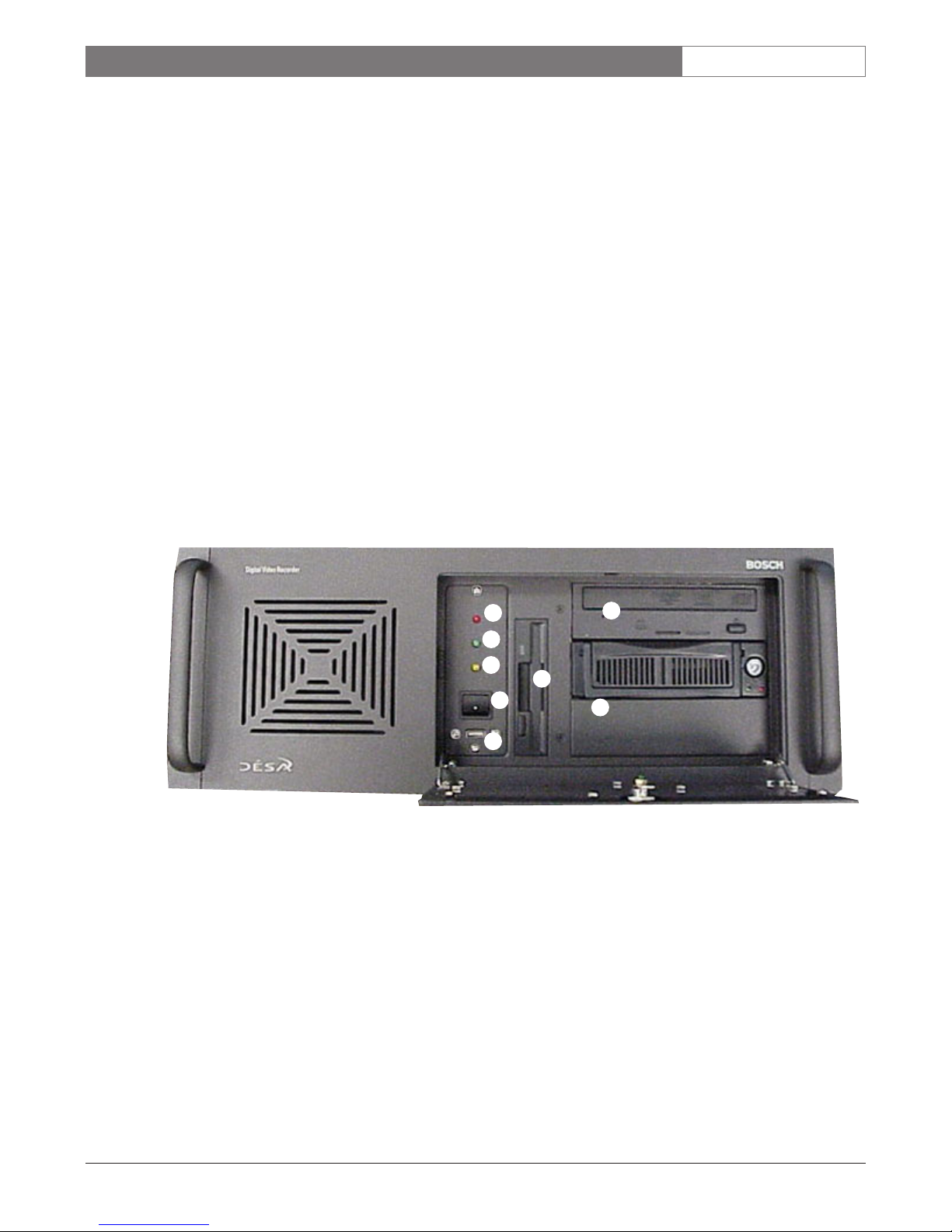
5.2 Front Panel (Inside the DÉSA
XL
door)
1System HDD LED
2 Run LED
3System Power LED
4Secondary Power Switch
5USB Port
6 Floppy Disk Drive
7 Removable OS Drive
8 DVD-writer
8
6
4
7
3
1
5
2
EN|11
Bosch Security Systems | November 17, 2004
DÉSAXL| Instruction Manual | Installation
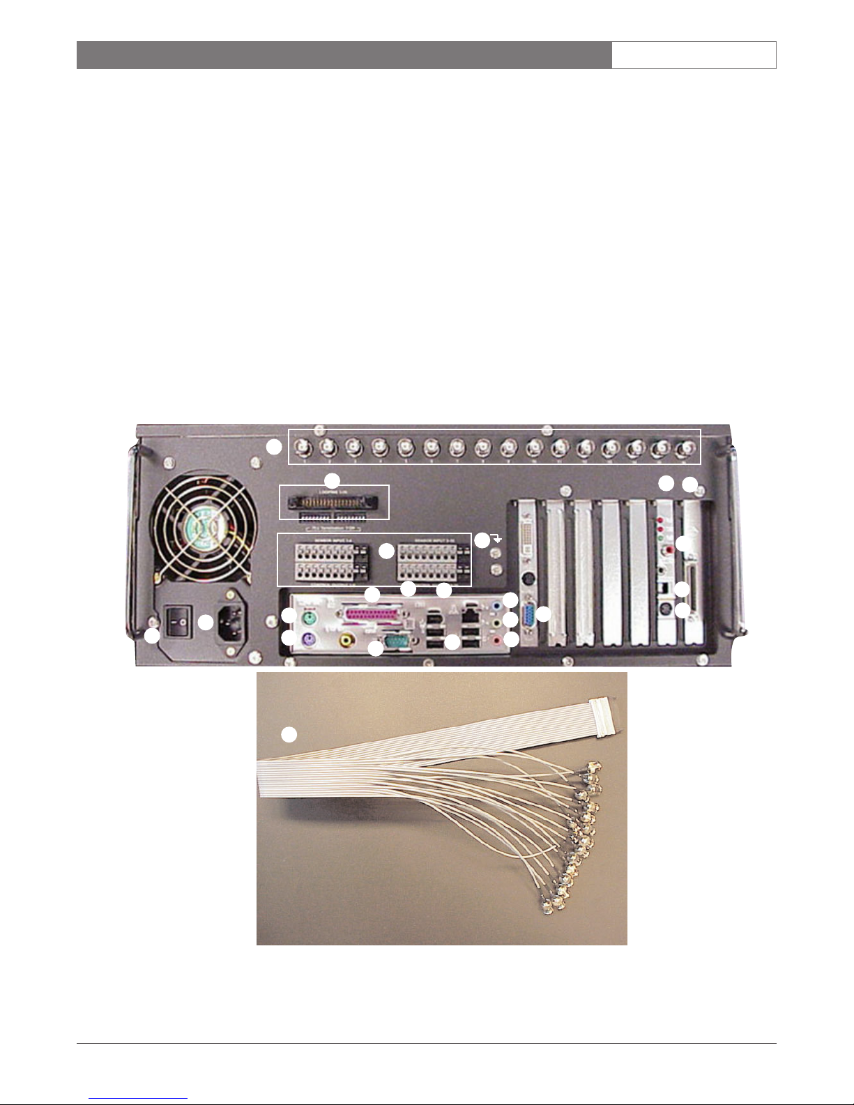
5.3 Rear Panel
1 Camera BNC Inputs (1-16)
2 Looping Port and Termination Switches
3Watchdog Card
A. External Monitor Output
B. RS-422 Output
C. DIN Connector (Connect to COM 1 with
Watchdog/PTZ Cable)
4SCSI Port
5Sensor and Control Connector Blocks
6Printer Port (Pink DB-25)
7IEEE-1394 Port
8Ethernet Port
9 Audio In (Light Blue)
10 Primary Power Disconnect Switch
11 P ower Cord Receptacle
12 Mouse Port (Green)
13 Keyboard Port (Purple)
14 C OM 1
15 U SB Ports
16 Audio Out (Light Green)
17 PC Monitor Port (Blue)
18 Microphone In (Pink)
19 LT C 8508/01 Looping Cable
20 Grounding Shield Lug*
*NOTE: Twisted shielded cable is required for all
sensor inputs and auxiliary outputs.
12
13
16
18
9
17
10
11
15
14
3
4
C
B
A
1
5
19
2
6
7
8
20
Shield
EN|12
Bosch Security Systems | November 17, 2004
DÉSAXL| Instruction Manual | Installation
5.4 Basic Connections
5.4.1Connect cameras to BNC inputs labeled
1-16 or 1-8.
5.4.2 Connect the power cord (Ensure that the
Primary Disconnect Switch is in the OFF
(O) position).
5.4.3Connect Ethernet cable (if used; not supplied).
5.4.4 Connect Speakers (if used; not supplied).
5.4.5 Connect Microphone (if used; not supplied).
5.4.6 Connect Audio Source (if used).
5.4.7 Connect External Monitor (requires
BNC-RCA adapter; not supplied).
5.4.8 Connect PC Monitor (not supplied).
5.4.9 Connect Grounding Shield Lug*
*NOTE: Twisted shielded cable is required for all
sensor inputs and auxiliary outputs.
5.5 Connecting Bosch AutoDomes
5.5.1 Requires the Bosch LTC 8786 to convert
from RS-232 to Biphase (if used; not
supplied).
5.5.2 Connect the supplied Watchdog/PTZ
control cable to the RS-232 input, on
the LTC 8786.
5.5.3 Connect the 2-conductor shielded biphase
wire from the AutoDomes to the biphase
output on the LTC 8786. The connections
are polarity-sensitive; (+) positive, (-)
negative, (S) shield. Use 18 - 2 twisted
shielded Belden 8760 or equivalent.
5.5.4 The LTC 8786 is recommended for use in
most cases, and supports 16 biphase outputs.
Control of AutoDomes should only be done
from an LTC 5136 or the GUI interface at a
time (not to be used simultaneously).
NOTE: The LTC 8786 DOES NOT need to be
reconfigured from the factory.
5.6 Connecting Other Manufacturer’s
Domes
The DÉSAXLprovides two types of PTZ output:
•RS-232 (typically connected to a converter)
•RS-422
1. Top Pin (+) positive
2. Middle Pin (GND) ground
3. Bottom Pin (-) negative
NOTE: The Watchdog cable must be properly
connected to COM 1 and the DIN connector on
the Watchdog Card.
5.7 Connecting Sensor Inputs
•Connect one of the two conductors to the
proper sensor input 1-16 or 1-8.
•Connect the other conductor to the (GND)
ground input of the sensor input.
5.8 Connecting Control Outputs
•Connect one of the two conductors to the
proper control output 1-16 or 1-8.
•Connect the other conductor to the (GND)
ground input of the Control.
EN|13
Bosch Security Systems | November 17, 2004
DÉSAXL| Instruction Manual | Installation
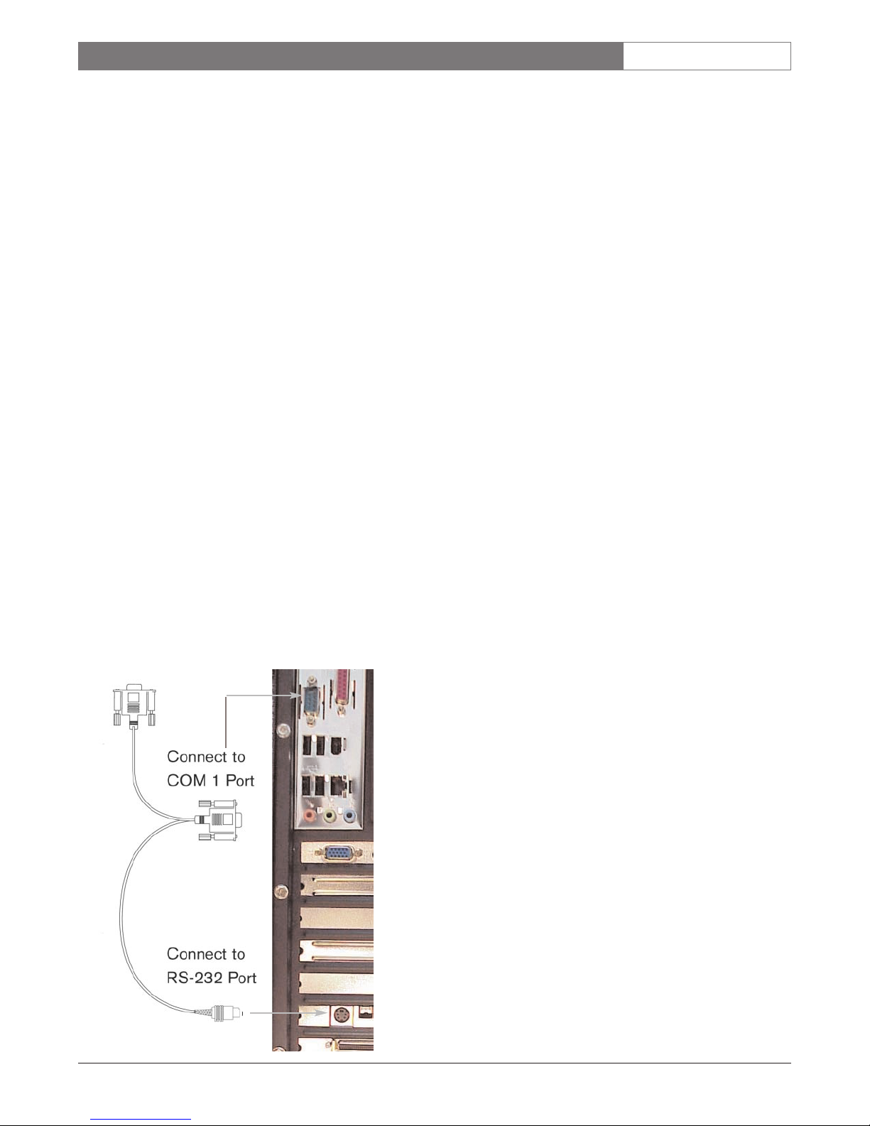
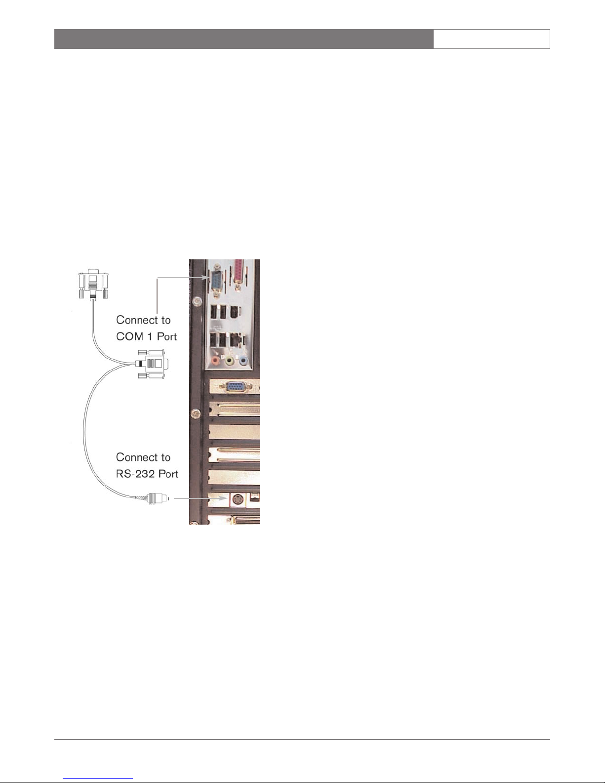
5.9 Connecting the Watchdog Cable
The purpose of the Watchdog cable and card is to
provide:
•Sensor Input Functions
•Control Output Functions
•PTZ Control
•Watchdog Monitoring Functions
•Remote Event Status
NOTE: The Watchdog cable must always be used so
the system functions properly.
5.9.1 Locate the supplied cable with the two DB-9
connectors, and one DIN connector end.
5.9.2 Connect the DB-9 connector end (that has two
cables going into it) to COM 1.
5.9.3 Connect the DIN (barrel connector) to the
receiver on the Watchdog Card.
5.9.4 Connect the DB-9 connector (with a single
cable) to a PTZ converter box (if used).
EN|14
Bosch Security Systems | November 17, 2004
DÉSAXL| Instruction Manual | Initial DÉSAXLPower-up
6INITIAL DÉSA
XL
POWER-UP
Once all appropriate connections to the DÉSAXLhave been made, begin the power up process:
•Turn on the Primary Power Switch on the rear panel of the DÉSA
XL
.
• Briefly push and release the Secondary Power Switch on the front panel of the
DÉSA
XL
.
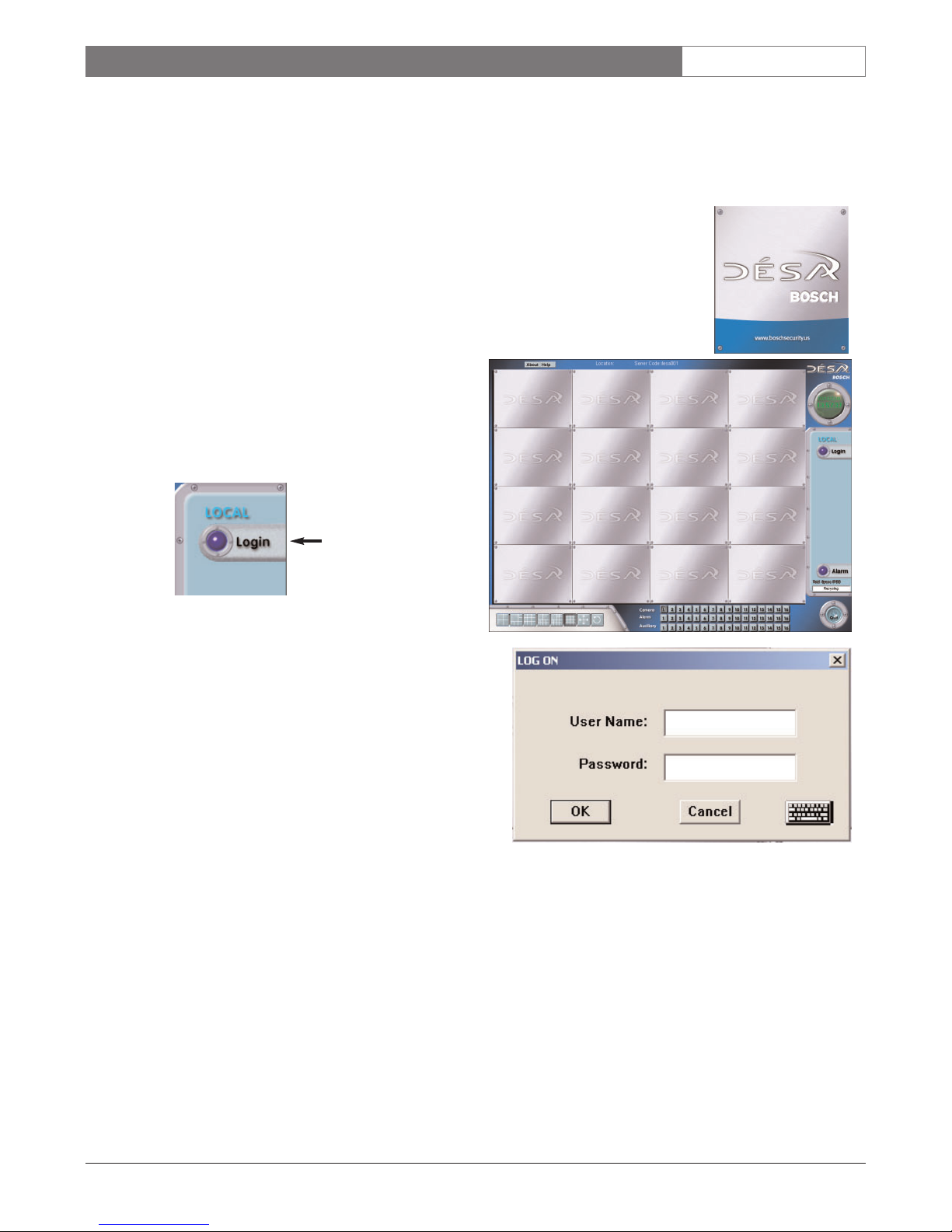
6.1 DÉSAXLLaunch Screen
• The DÉSAXLwill immediately start and launch the DÉSAXLapplication.
• The following screens appear while the DÉSA
XL
application is loading.
6.2 First Time Login
6.2.1 Once the DÉSAXLapplication has launched,
login to operate the system.
6.2.2 Click Login.
6.2.3 The default User Name and Password for
Administrator is ‘desa’ / ‘desa’ (lowercase letters).
6.2.4 The DÉSA
XL
application login button now
displays logout.
6.2.5 Click Setup and select the Passwords Tab. Enter a
new DÉSA
XL
User Password immediately. This is
covered in SECTION 8.9.
NOTE: DO NOT leave the DÉSAXLpassword as the default.

EN|15
Bosch Security Systems | November 17, 2004
DÉSAXL| Instruction Manual | Initial DÉSAXLPower-up
6.3 Initial Power-up Administrative Access
Initial Power-up: The DÉSAXLruns on a Windows XP Professional Platform, and starts up under the DÉSA
XL
User. In order to make any changes to the operating system, including the IP Address, you must logoff, and
login as the Administrator.
To Login as the Windows ADMINISTRATOR:
6.3.1 Login to the DÉSA Application as the Administrator.
6.3.2 Exit the DÉSA Application as follows:
Push and hold CTRL/ALT/SHIFT, and then F4 to exit the DÉSA Application only if
you are the Administrator.
6.3.3 Click START and logoff. When promted, if you are sure, click logoff and IMMEDIATELY hold down
the left SHIFT key.
6.3.4 The logon to Windows dialog appears.
6.3.5 The Username and Password are as follows:
a. Username: administrator
b. Password: desa
6.3.6 Windows will logon as the Administrator and immediately prompt for a new password. This is
recommended for security reasons.
a. Username: Administrator
b. New Password:
WARNING: If you forget your Windows password, a recovery procedure will be required to reset the
default password.
EN|16
Bosch Security Systems | November 17, 2004
DÉSAXL| Instruction Manual | Main Screen
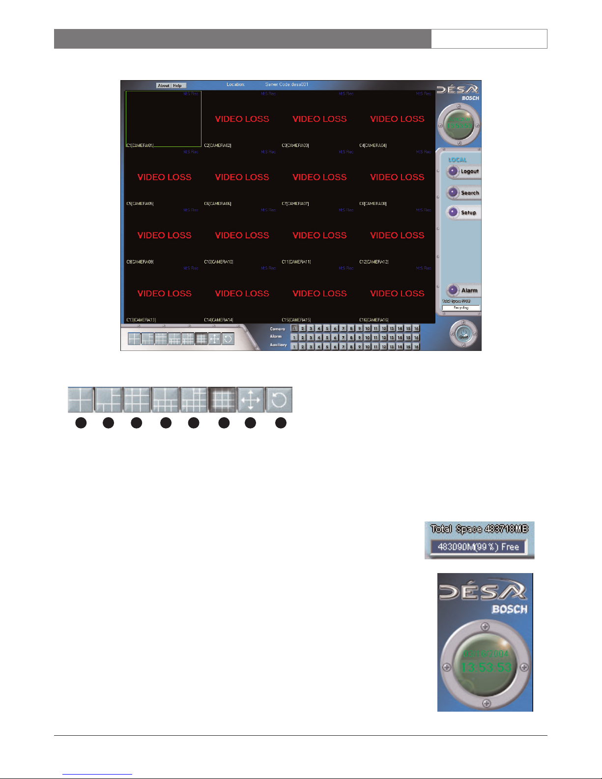
7 MAIN SCREEN
7. 1 Live Display Buttons
7. 2Storage Indicator
There are two parts to the Storage Indicator:
1. Total Space is the total amount of storage available on the system.
2. Free is the amount of free space available before the video starts to
Recycle (Overwrite).
7. 3Time and Date Display
Displays the current time and date of the Server.
NOTE: Do not change the time and date of the server while the DÉSA
XL
application
is running. Close the DÉSA
XL
application before making any changes. (Refer to
SECTION 6.3)
1. Quad
2. Five Plus One
3. Three By Three
4. Eight Plus Two
5. Twelve Plus One
6. Four By Four
7. Full Screen
8. Sequence
1 2 3 4 5 6 7 8
EN|17
Bosch Security Systems | November 17, 2004
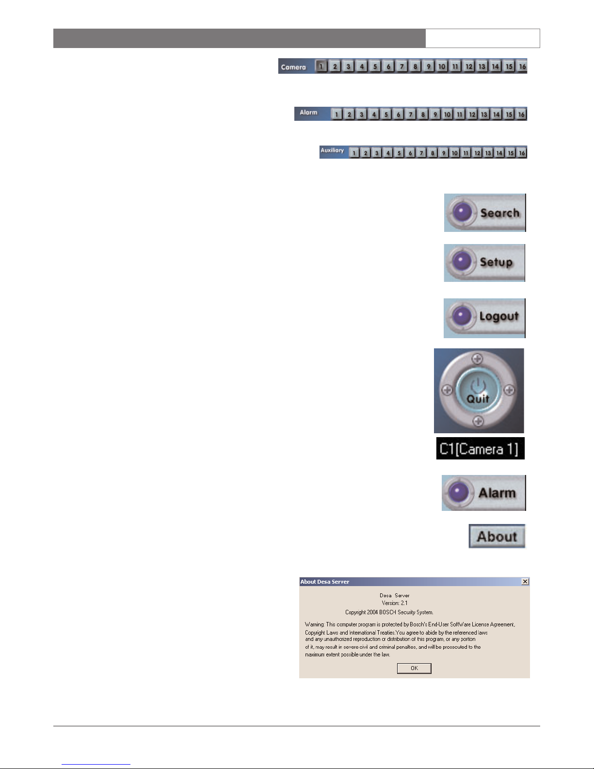
DÉSAXL| Instruction Manual | Main Screen
7. 4 Camera Indicators
When depressed, it indicates when the cameras are
recording.
7. 5 Alarm Sensor Indicators
When depressed, it indicates when a sensor input has been triggered.
7. 6 Auxiliary Control Indicators
When depressed, it indicates when the control output is
triggered (active). The auxiliary output can be manually activated by depressing the individual control button.
7. 7Search Button
This button opens the server Search screen.
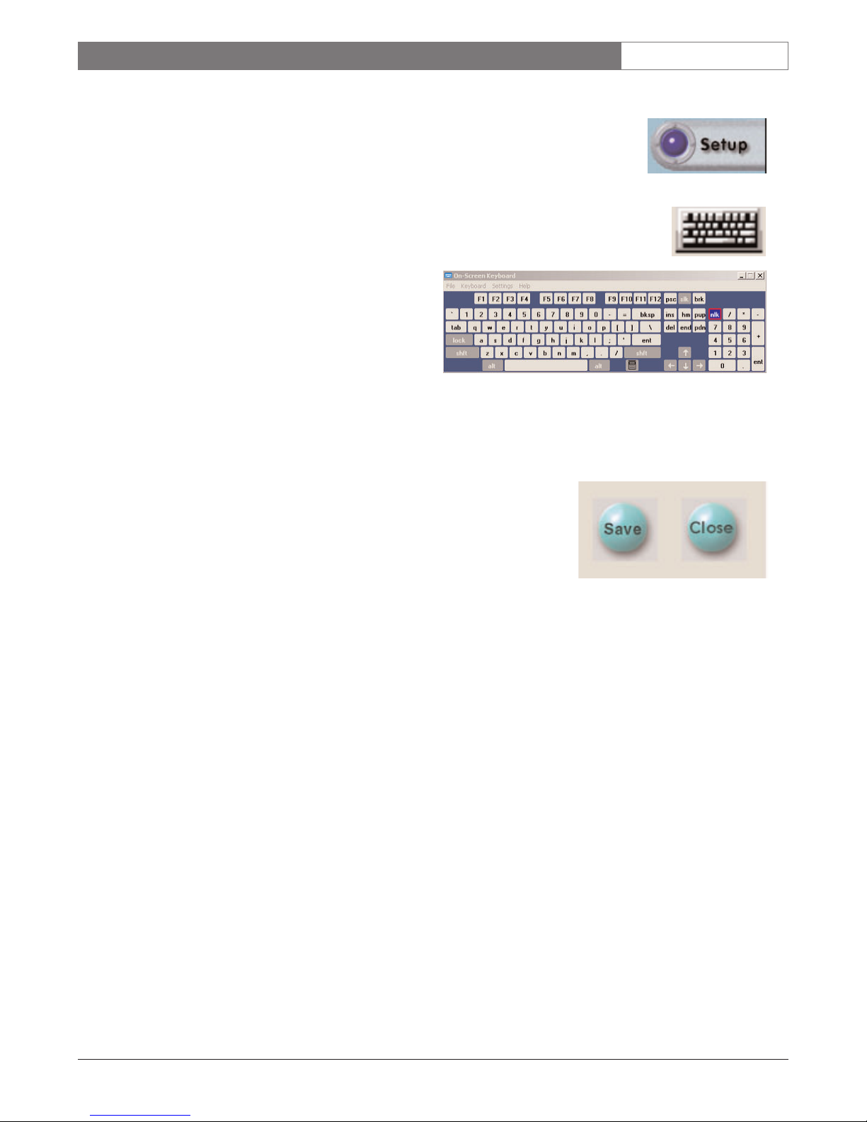
7. 8 S e t up Button
This button opens the Setup menus.
7. 9 Login / Logout Button
This button restricts access to the system functions, requiring a user name and
password to access the system. When logged out of the system, the functionality of
the system is restricted to the configuration of the Logout User.
7. 10 Quit Button
Quit can only be used if the system user has been given permission in the Password
Setup menu, (SECTION 8.9), to exit the system.
7. 11 Item Description In Cameos
C1, C2 etc. indicates the physical input on the system. The [ ] contains the
description of the Camera Setup, in the Hardware Setup menu.
7. 12 Event Alert Button
The Alarm button on the Main Display flashes when there’s an alarm. Click Alarm
to open Log Records and allow comments to be made for each event.
7. 13 About Button
This button displays the current version of DÉSA
XL
Server Software.
EN|18
Bosch Security Systems | November 17, 2004
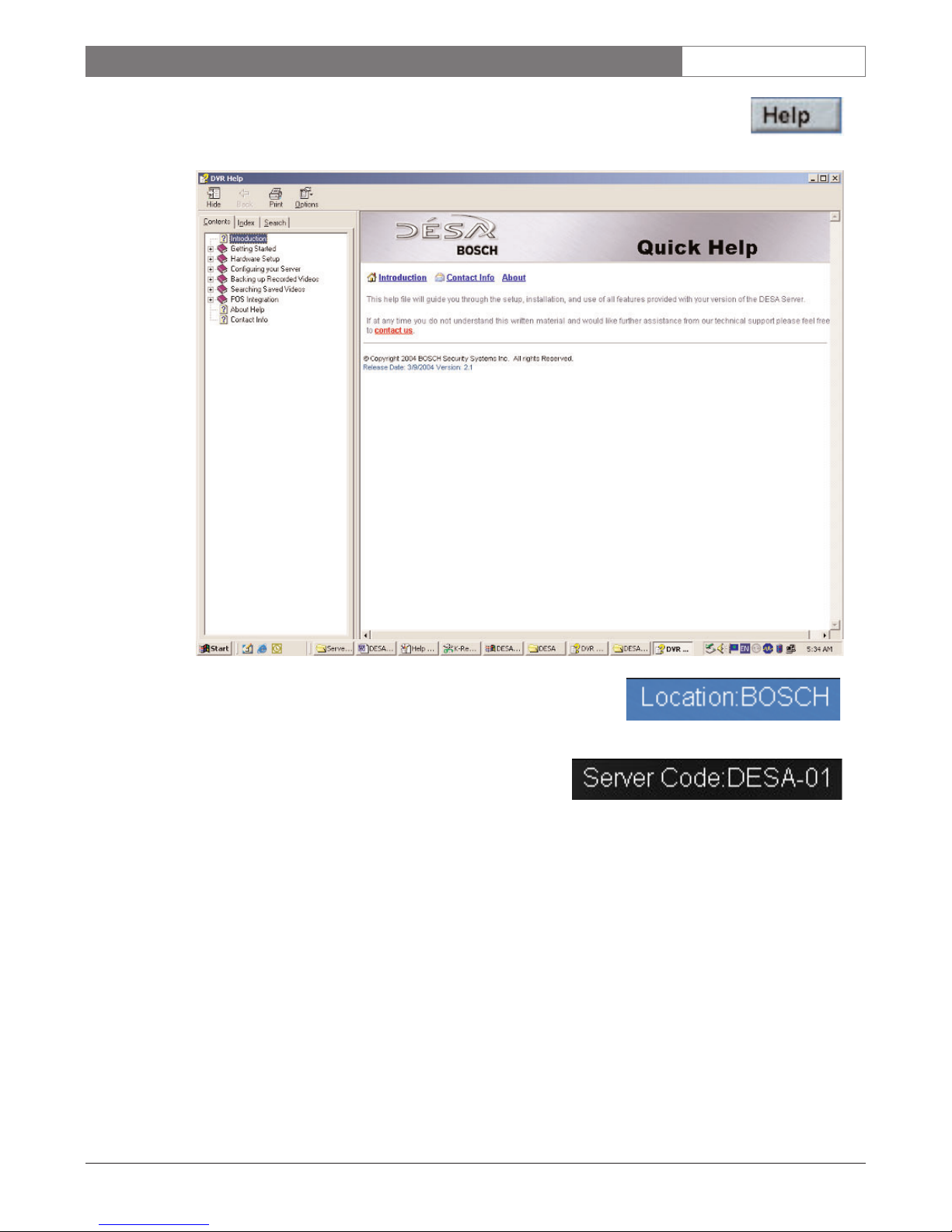
DÉSAXL| Instruction Manual | Main Screen
7. 14 Help Button
Click Help to open the Help window that contains basic user functions and
troubleshooting.
7. 15 Location
The Location is found in the top center of the DÉSAXL’s main screen,
and displays information about the unit.
7. 16 Server Code
The Server Code is found in the top center of the DÉSAXL’s
main screen, and is used by the remote software to identify
each DÉSA
XL
System. This code must be seven (7) characters
long, and unique for every unit.
EN|19
Bosch Security Systems | November 17, 2004
DÉSAXL| Instruction Manual | System Setup Options
8 DÉSAXLSYSTEM SETUP OPTIONS (Setup Button)
Click Setup to initiate System Setup.
8.1 Integrated Keyboard
8.1.1 The Integrated Keyboard icon is located at the
bottom of the Setup screens, and eliminates need
for a physically connected keyboard after initial
setup.
8.1.2 The Integrated Keyboard stays open while moving
between tabs. When finished, the Integrated
Keyboard must be closed.
NOTE: At times, a keyboard may need to be
reconnected to the system, so be sure the supplied
keyboard is available for advanced system
configuration.
8.2 Save and Close Buttons
8.2.1 Save is used to retain any changes made in
each of the Setup menu tabs.
8.2.2 To save your changes, press Save before moving between tabs, and
before pressing Close.
8.2.3 Close is used to close out of the Setup menus, exiting to the Main Display.
8.2.4 Closing the Setup menu without clicking Save results in no changes being made.
EN|20
Bosch Security Systems | November 17, 2004
DÉSAXL| Instruction Manual | System Setup Options
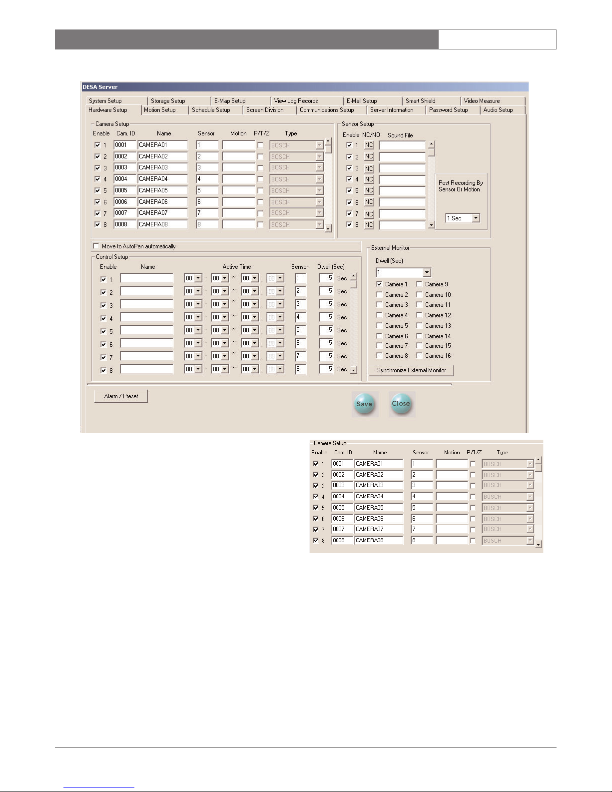
8.3 Hardware Setup Tab
8.3.1 Camera Setup
8.3.1.1 Use the Camera Setup section of the
Hardware Setup tab to Enable (Disable)
cameras connected to the system. Check
the box to enable camera input; uncheck
the box to disable camera input.
NOTE: Unchecking the box for a camera also disables
that camera in the Screen Division tab, and in the External Monitor section of the Hardware Setup tab. Re-enabling
the camera DOES NOT automatically re-enable these settings. The settings need to be manually restored.
8.3.1.2 Cam. ID enables logical numbering of every camera in the system; typically used when multiple
DÉSA
XL
comprise a large system. Cam. ID directly relates to AutoDomes connected to the DÉSA
XL
system for control. The Cam. ID must match the address of the connected AutoDome.
8.3.1.3 Name allows a camera description to be associated with each camera. Character length is limited to
13 uppercase characters or 14 lowercase characters.
8.3.1.4 Sensor associates the physical sensors (alarm inputs) to a specific camera. Multiple sensors can be
associated with multiple cameras by separating the sensor numbers by commas i.e. 1,2,3, etc.
EN|21
Bosch Security Systems | November 17, 2004
DÉSAXL| Instruction Manual | System Setup Options
8.3.1.5 Motion associates motion activity to other cameras in the system, to record based on another
camera’s motion. Multiple cameras can be associated to multiple other cameras’ motion.
(Example - 2, 3, 4).
8.3.1.6 PTZ: If checked, designates that the camera connected is a PTZ type camera.
8.3.1.7 Ty pe : If the PTZ box has been checked for any camera, the type of PTZ protocol to be used can be
selected. The default is Bosch biphase protocol. NOTE: Biphase and Pelco
®
protocols have been tested
and verified. All other protocols have yet to be tested.
8.3.1.8 The scroll bar on the right side of the display allows scrolling up or down to reveal additional
cameras.
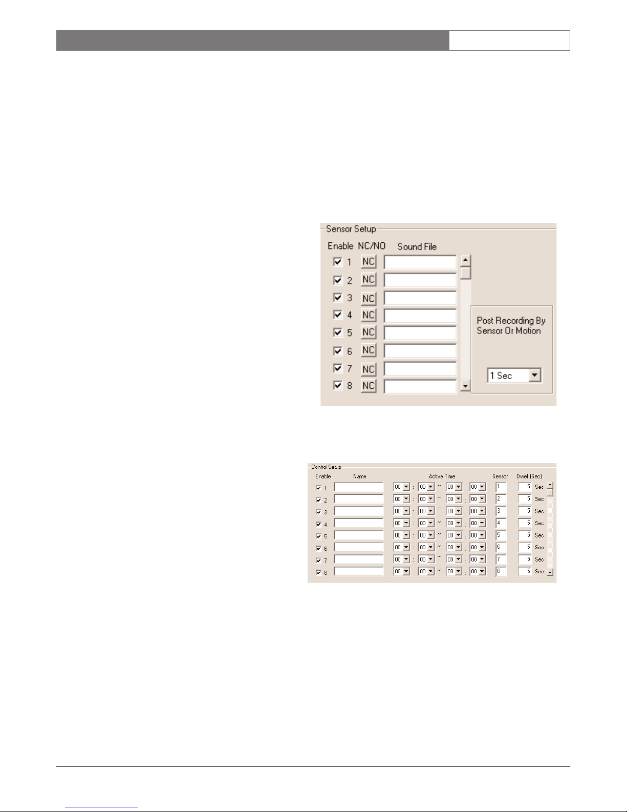
8.3.2 Sensor (Alarm) Setup
8.3.2.1 Enable (Disable): If checked, enables an
alarm input; remove the check to disable
the alarm input.
8.3.2.2 NC/NO: Press NC/NO to toggle between
normally closed or normally open alarm
input.
8.3.2.3 Sound File: Any .wav file can be loaded into
the Wave folder in the following directory:
C:\DESA\Wav.
This .wav file provides audible
indication that an alarm input has been
triggered (example - greeting.wav).
8.3.2.4 Recording Time By Sensor, Motion sets 1 to 60
seconds of global post-alarm recording once
an alarm has been triggered.
8.3.3 Control Setup
8.3.3.1 Enable (Disable) activates/deactivates the
designated Control Output.
8.3.3.2 Name designates a camera description to
be associated with each Control Output.
Length is limited to 13 uppercase
characters or 14 lowercase characters.
8.3.3.3 Auto ON/OFF Time: Setting an ON and
OFF time of day defines the period of
time (each day) during which the control
is activated.
8.3.3.4 Sensor (Alarm) associates the physical
sensor inputs to a specific Control
Output. Multiple sensors can be
associated with multiple auxiliaries, by
separating the alarm numbers by
commas i.e. 1,2,3, etc.
8.3.3.5 Dwell is the duration that the Control will be closed, once triggered by an sensor input. The
maximum is 9999 seconds, individually.
EN|22
Bosch Security Systems | November 17, 2004
DÉSAXL| Instruction Manual | System Setup Options
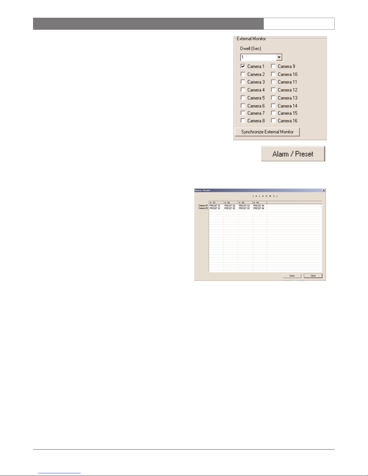
8.3.4 External Monitor
This screen is used to select cameras to be displayed on the analog monitor
output.
8.3.4.1 Dwell (Sec) is the time that each selected camera will be
displayed during sequence operation. Cameras are available
only if Enabled in Camera Setup.
Synchronize External Monitor: Once cameras have been added and
saved, press this button to reset the sequencing.
8.3.5 PTZ Camera Alarm/Preset Setup
8.3.5.1 This option can only be used if there is a camera with
PTZ selected in Camera Setup.
8.3.5.2 Press Alarm/Preset to display the Setup
screen.
8.3.5.3 Cameras with PTZ selected appear on the
left side of the chart, and across the top are
the sensors (alarm inputs).
8.3.5.4 Click the box intersecting the desired
camera with the appropriate alarm. A
dropdown box with 1-10 presets will appear.
Select the preset to be associated with that
alarm input.
8.3.5.5 The same preset can be assigned to as many
of the cameras or alarm inputs as desired.
EN|23
Bosch Security Systems | November 17, 2004
DÉSAXL| Instruction Manual | System Setup Options
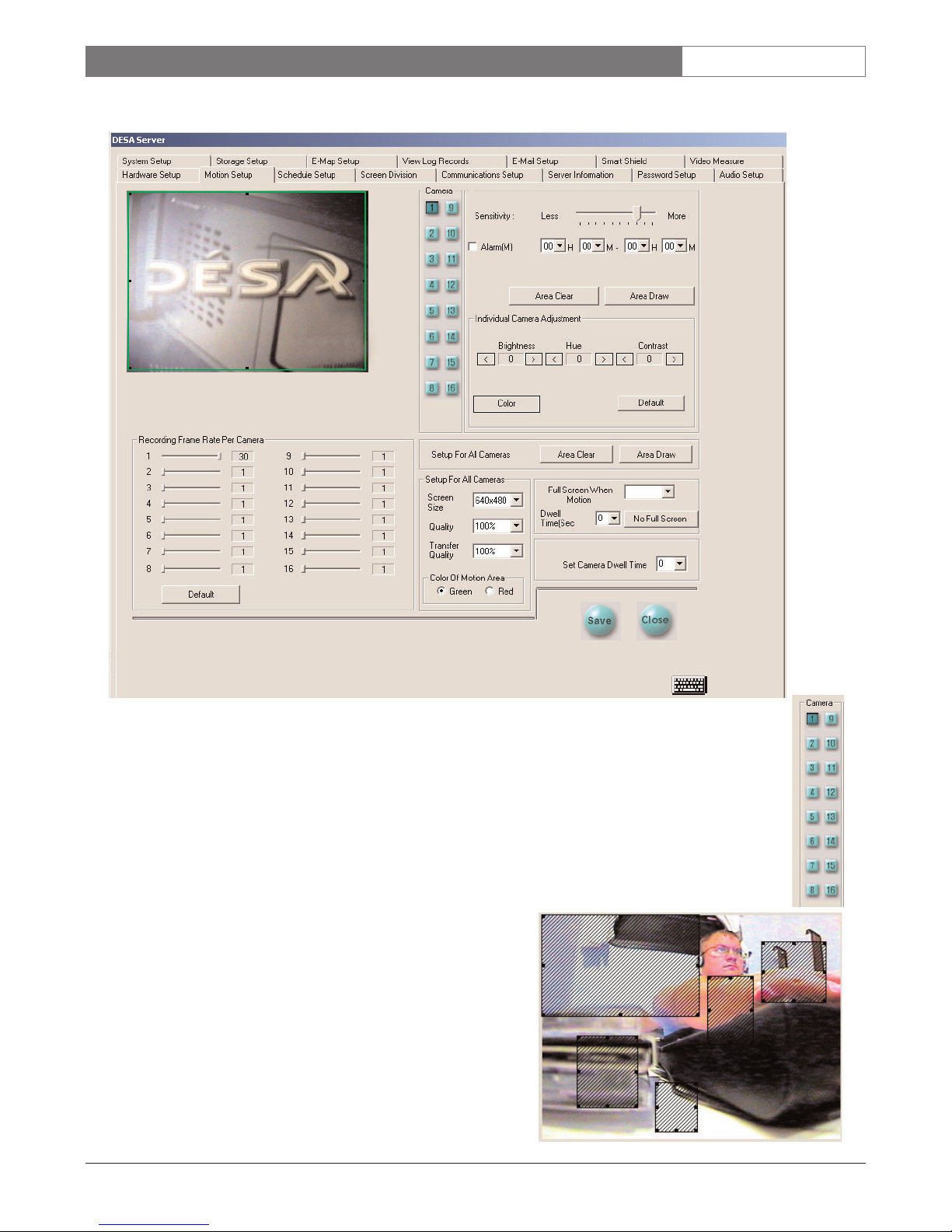
8.4 Motion Setup Tab
8.4.1 Camera Selection
Select the camera number to be set for motion detection, sensitivity, and individual camera adjustment.
8.4.2 Motion Detection Area
Use the mouse to draw the area in which activity is to be
detected. Up to five detection areas can be defined for each
camera.
 Loading...