


Bosch DDU S2 Plus User Manual
Display DDU S2 Plus
Manual
Version 1.0 9/16/2016

Table of contents
1 Preparation ........................................................................................................................................................... 4
2 Power Supply ....................................................................................................................................................... 5
3 Onboard Network Concept ................................................................................................................................ 6
4 Technical Data ...................................................................................................................................................... 7
5 Inputs and Outputs ........................................................................................................................................... 11
5.1 Input channels ................................................................................................................................................................................ 11
5.2 Output channels ............................................................................................................................................................................ 11
5.3 Communication channels .......................................................................................................................................................... 11
6 Mechanical Drawing .......................................................................................................................................... 13
7 Starting up ......................................................................................................................................................... 14
7.1 Before starting ................................................................................................................................................................................ 14
7.2 First display configuration (Quick Start) ............................................................................................................................... 18
8 Display Configuration ....................................................................................................................................... 22
8.1 Display page setup ....................................................................................................................................................................... 22
8.2 Display element configuration ................................................................................................................................................. 23
8.3 LEDs .................................................................................................................................................................................................... 32
8.4 Page select ....................................................................................................................................................................................... 37
8.5 Display + LED brightness ........................................................................................................................................................... 48
8.6 Math + condition channels ....................................................................................................................................................... 59
8.7 Condition channels ....................................................................................................................................................................... 63
9 CAN Bus .............................................................................................................................................................. 66
9.1 CAN bus trivia ................................................................................................................................................................................. 66
9.2 CAN input ......................................................................................................................................................................................... 67
9.3 CAN output ...................................................................................................................................................................................... 75
10 Analog and Frequency Inputs .......................................................................................................................... 79
10.1 Features ............................................................................................................................................................................................. 79
10.2 Analog inputs .................................................................................................................................................................................. 79
10.3 Configuring inputs ........................................................................................................................................................................ 80
10.4 Configuring computed sources ............................................................................................................................................... 92
10.5 Hysteresis ......................................................................................................................................................................................... 94
11 Online Measurement ......................................................................................................................................... 98
11.1 Achieving an online connection .............................................................................................................................................. 98
11.2 Setting up an online measurement ..................................................................................................................................... 100
11.3 Online calibration of measurement channels ................................................................................................................. 106
11.4 Group adjustment ...................................................................................................................................................................... 108
11.5 Online calibration of multipoint adjustment channels ................................................................................................ 110
12 Error Memory .................................................................................................................................................. 113
12.1 General note ................................................................................................................................................................................. 113
12.2 Error memory representation in RaceCon ........................................................................................................................ 113
12.3 Information on errors available from the error memory ............................................................................................ 115
12.4 Configuration ............................................................................................................................................................................... 119
Table of Contents
2 / 136 DDU S2 PLUS Manual Bosch Motorsport

13 Firmware .......................................................................................................................................................... 121
13.1 Firmware and configuration ................................................................................................................................................... 121
13.2 Firmware update ......................................................................................................................................................................... 121
14 Clone the Unit ................................................................................................................................................. 124
15 GPS Sensor ...................................................................................................................................................... 125
15.1 GPS (Global Positioning System) .......................................................................................................................................... 125
15.2 Protocol .......................................................................................................................................................................................... 125
15.3 Sensor recommendation ......................................................................................................................................................... 125
15.4 Measurement labels .................................................................................................................................................................. 128
15.5 GPS troubleshooting ................................................................................................................................................................. 129
16 Fuel Consumption Calculation ...................................................................................................................... 131
16.1 Setting up fuel consumption calculation and tank mangement ............................................................................. 131
16.2 Fuel consumption diagnosis/counter reset ..................................................................................................................... 132
16.3 Example .......................................................................................................................................................................................... 133
17 RaceCon Shortcuts ......................................................................................................................................... 134
Table of Contents
Bosch Motorsport DDU S2 PLUS Manual 3 / 136

Preparation
Use the DDU 8 only as intended in this manual. Any maintenance or repair must
be performed by authorized and qualified personnel approved by Bosch Motor‐
sport.
Operation of the DDU 8 is only certified with the combinations and accessories
that are specified in this manual. The use of variant combinations, accessories,
and other devices outside the scope of this manual are only permitted when they
have been determined to be compliant from a performance and safety stand‐
point by a representative from Bosch Motorsport.
Read the manual carefully and follow the application hints step by step. Don’t
hesitate to contact us, contact data can be found on the last page of this docu‐
ment.
Disclaimer:
Due to continuous enhancements we reserve the rights to change any illustra‐
tions, photos and technical data within this manual.
Please retain this manual for your records.
In this document all screenshots are created by way of example for other dis‐
plays.
Please consider this and replace the product names with the name of your prod‐
uct.
Notice
In this document all screenshots are created by way of example
for other displays.
Please consider this and replace the product names with the
name of your product.
1
1 | Preparation
4 / 136 DDU S2 PLUS Manual Bosch Motorsport

Power Supply
Bosch Motorsport software is developed for Windows system software. Connect
the Ethernet line to your computer and install the driver. Read the manual care‐
fully and follow the application hints step by step.
Please ensure that you have a good ground installation. That means:
▪ A ground that has a solid, low resistance connection to the negative battery
terminal
▪ Connection should be free from dirt, grease, paint, anodizing, etc..
▪ Use large diameter wire
▪ More metal‐to‐metal contact is better!
The following notations for power signals are used:
▪ KL 15 is a switched battery rail controlled by the IGN‐switch
▪ KL 30 is an unswitched battery positive rail (same as battery positive terminal)
▪ KL 31 is an unswitched ground rail (same as battery negative terminal)
Be careful to observe current limits of wires and connector pins!
2
Power Supply | 2
Bosch Motorsport DDU S2 PLUS Manual 5 / 136
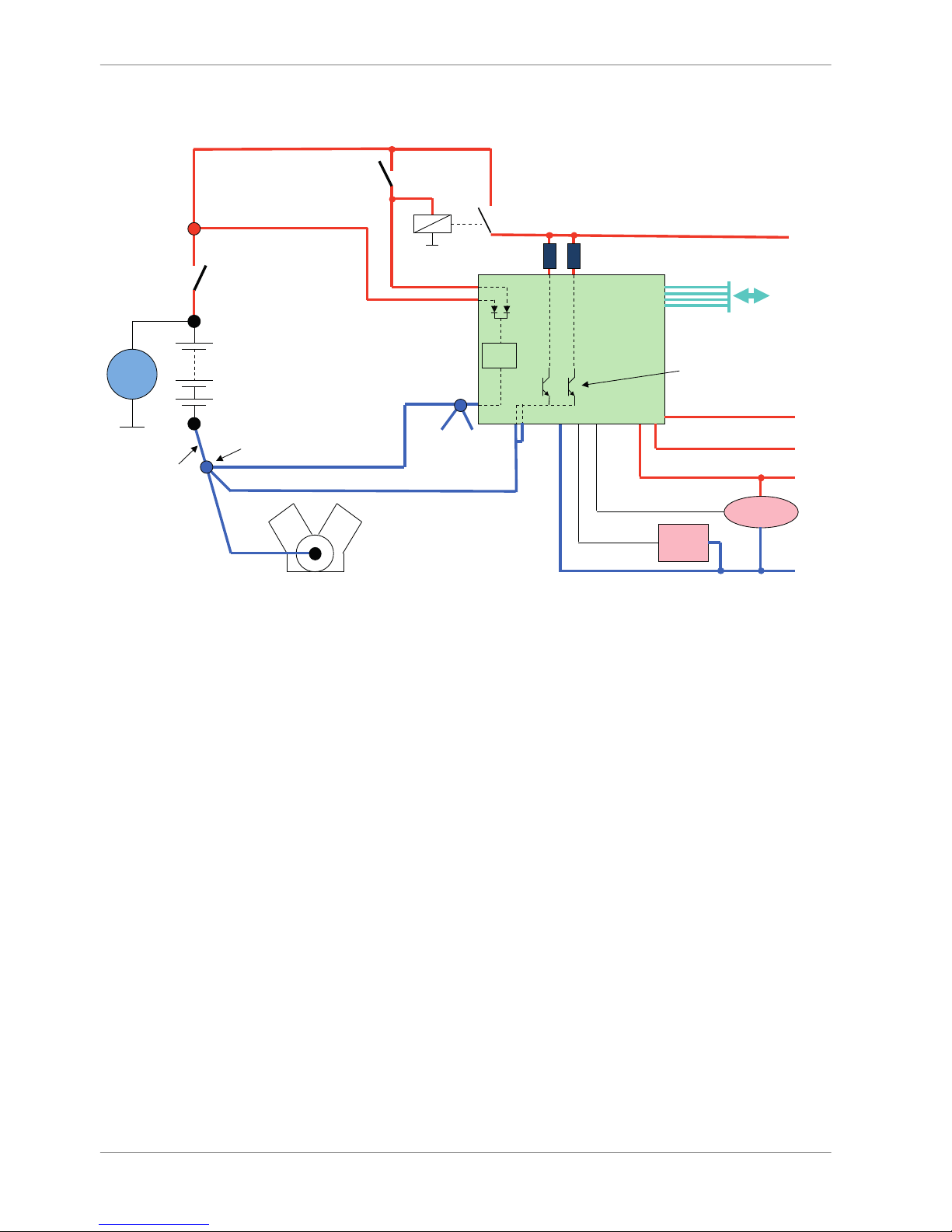
Onboard Network Concept
G
Engine_GND
GND_Starpoint
Chassis
KL31
LS_GND_1
LS_GND_2
Main
Switch
UBAT
Star connection
(term30)
positive terminal
Electric Loads
IGN-
Switch
KL15
SENSPWR5
SENSGND
active
Sensor
ANA_IN(xx)
NTC
Sensor
ANA_IN(xy)
switched pos. terminal
Star connection
dig. sensors
(e.g. wheelspeed)
µC
As short as
possible
SENSPWR10
UBATT_FUSE
KL30
LS_SWITCH1…4
Bosch Motorsport
diagnosis connector
PC
DDU
3
3 | Onboard Network Concept
6 / 136 DDU S2 PLUS Manual Bosch Motorsport
Technical Data
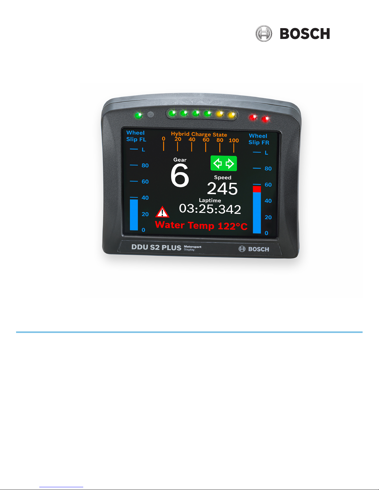
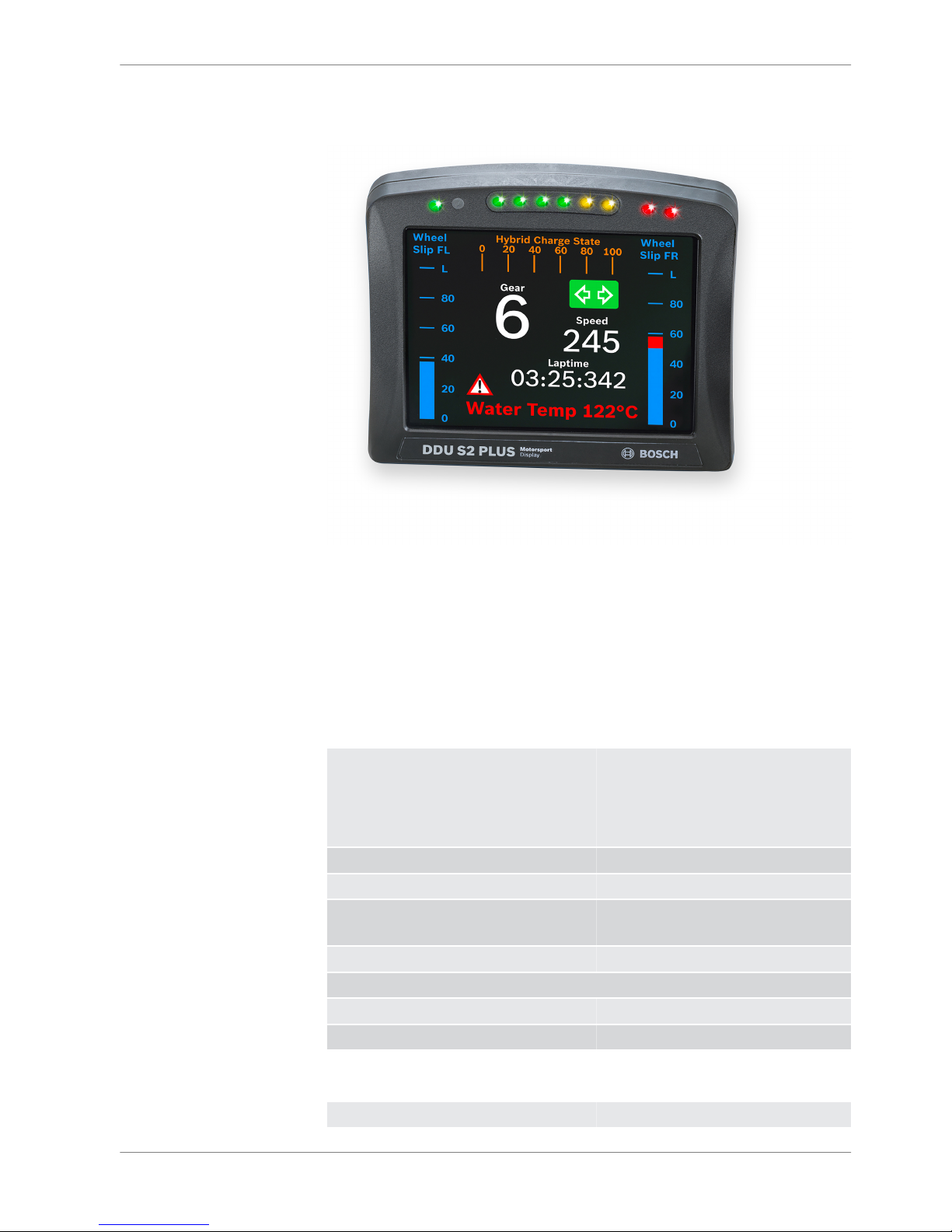
The display DDU S2 PLUS integrates a programmable full color TFT screen for
motorsport applications. It allows for synchronized acquisition and visualization
of analogue and digital input channels as well as input via CAN. The DDU S2
PLUS can be used as stand alone display or in combination with the Bosch ECU
family. It can be combined e.g. as copilot display with Bosch DDU 7 or DDU 8.
Additional devices can be connected via Ethernet and CAN buses. CAN in and
out is freely configurable.
Application
Display ▪ 5,7” graphic color display
▪ 12 user configurable display pages
▪ 10 multicolor freely configurable
(RGB) LEDs
Resolution 640 x 480 pixel
Supported image file formats bmp, gif, jpg, png, tif
Converters 8 kHz AD converters with digital low
pass filter
Configurable math channels
User configurable CAN in/out messages
Sampling rate Max. 1,000 Hz for all channels
RS232 GPS input
Mechanical Data
Size 148 x 126 x 32 mm
4
Technical Data | 4
Bosch Motorsport DDU S2 PLUS Manual 7 / 136

Weight 440 g
Protection Classification IP54 to DIN 40050, Section 9, Issue
2008
Operating temperature internal ‐20 to 85°C
Operating temperature Display ‐20 to 70°C
Max. vibration Vibration profile 1 (see Appendix or
www.bosch‐motorsport.com)
Electrical Data
Supply voltage 8 to 18 V
Max. power consumption (w/o loads) 14 W at 14 V
Inputs
Page/brightness selection Configurable
Analog channels 6
Speed inputs (Hall) 2
Input range 0 to 5 V
Resolution 12 bit
Switchable pull up resistor 3 kOhm
Outputs
Sensor supply 5 V ± 1 % (350 mA) 1
Sensor supply 10 V ± 1 % (350 mA) 1
Environment
External switch for page selection, 12
steps
B 261 209 658‐01
External switch for brightness adjust‐
ment or page selection, 6 steps
B 261 209 659‐01
Connectors and Wires
Motorsport connector
AS 2‐14‐35PN at DDU S2 PLUS
37 pins
Mating connector
AS 6‐14‐35SN
F 02U 000 453‐01
Communication
CAN interfaces 2
Ethernet 100BaseT 2
Sync 1
RS232 1 GPS
4 | Technical Data
8 / 136 DDU S2 PLUS Manual Bosch Motorsport

Configuration via RaceCon Over Ethernet or MSA‐Box II
Pin Assignment
1 Ethernet 2 RX ‐
2 Ethernet 2 RX +
3 Terminal 15
4 Ground
5 Unused
6 Unused
7 Unused
8 Unused
9 Ethernet 1 RX ‐
10 Ethernet 1 TX ‐
11 REV_IN
12 REV_IN
13 Sensor supply 10 V
14 Sensor supply 5 V
15 ANA_IN_1
16 ANA_IN_2
17 ANA_IN_3
18 ANA_IN_4
19 Ethernet 2 TX ‐
20 Ethernet 2 TX +
21 RS232 GPS TX
22 Screen Ethernet
23 ANA_IN_5
24 Ethernet 1 RX +
25 Ethernet 1 TX +
26 ANA_IN_6
27 Unused
28 Synchronization
29 CAN1_H
30 CAN1_L
31 RS232 GPS RX
32 Terminal 30
33 Unused
34 Unused
35 CAN2_H
36 CAN2_L
37 Sensor ground
Technical Data | 4
Bosch Motorsport DDU S2 PLUS Manual 9 / 136

Installation Notes
The required software (.pst file) for this device is available in the download area
of our homepage www.bosch‐motorsport.com.
4 | Technical Data
10 / 136 DDU S2 PLUS Manual Bosch Motorsport

Inputs and Outputs
Input channels
Analog inputs
The DDU 8 analog inputs accept an input signal of 0 to 5 V. A 3.01 kOhm pull‐up
resistor can be activated by software.
Digital inputs
The digital inputs of the DDU 8 accept 0 V to 5 V signals of Hall‐effect sensors by
default. Connect the output of the Hall‐effect sensor to the REVn.
Output channels
Sensor power supply
The DDU 8 has two types of sensor power supply: 5 V and 10 V regulated volt‐
age. The regulated 5 V and 10 V outputs can deliver 350 mA each. They are short
circuit protected to battery voltage and GND.
Communication channels
CAN bus
The DDU 8 has two CAN buses configurable as input and output. Different baud
rates are selectable. Please note that the DDU 8 does not contain any CAN termi‐
nation resistors. Thus the CAN termination resistors need to be integrated into
the wiring loom.
Ethernet channels
The DDU 8 has two 100 MBit full duplex Ethernet communication port. The port
is internally connected with an Ethernet switch. The Ethernet port has 'cable auto
crossover' functionality.
RS232 ports
The DDU 8 has one RS232 serial port. Baud rate for the port is programmable.
RS232 port is reserved for GPS receiver.
5
5.1
5.1.1
5.1.2
5.2
5.2.1
5.3
5.3.1
5.3.2
5.3.3
Inputs and Outputs | 5
Bosch Motorsport DDU S2 PLUS Manual 11 / 136

Vehicle diagnoses connector
The Bosch Motorsport vehicle diagnosis connector is used as a standard inter‐
face to connect the vehicle to a PC e.g. via a MSA‐Box II. Loom connector:
AS 0‐12‐35SN
Pin Name Description Used for DDU 8
Pin 1 Terminal 30 Permanent positive +
Pin 2 Terminal 15 Switched positive +
Pin 3 Terminal 31 GND +
Pin 4 CAN High Diagnostic CAN bus
Pin 16 CAN Low Diagnostic CAN bus
Pin 10 K‐Line ECU diagnosis
Pin 8 Ethernet RxD + Ethernet interface +
Pin 9 Ethernet RxD ‐ Ethernet interface +
Pin 11 Ethernet TxD + Ethernet interface +
Pin 12 Ethernet TxD ‐ Ethernet interface +
Pin 22 Screen Cable screen +
5.3.4
5 | Inputs and Outputs
12 / 136 DDU S2 PLUS Manual Bosch Motorsport
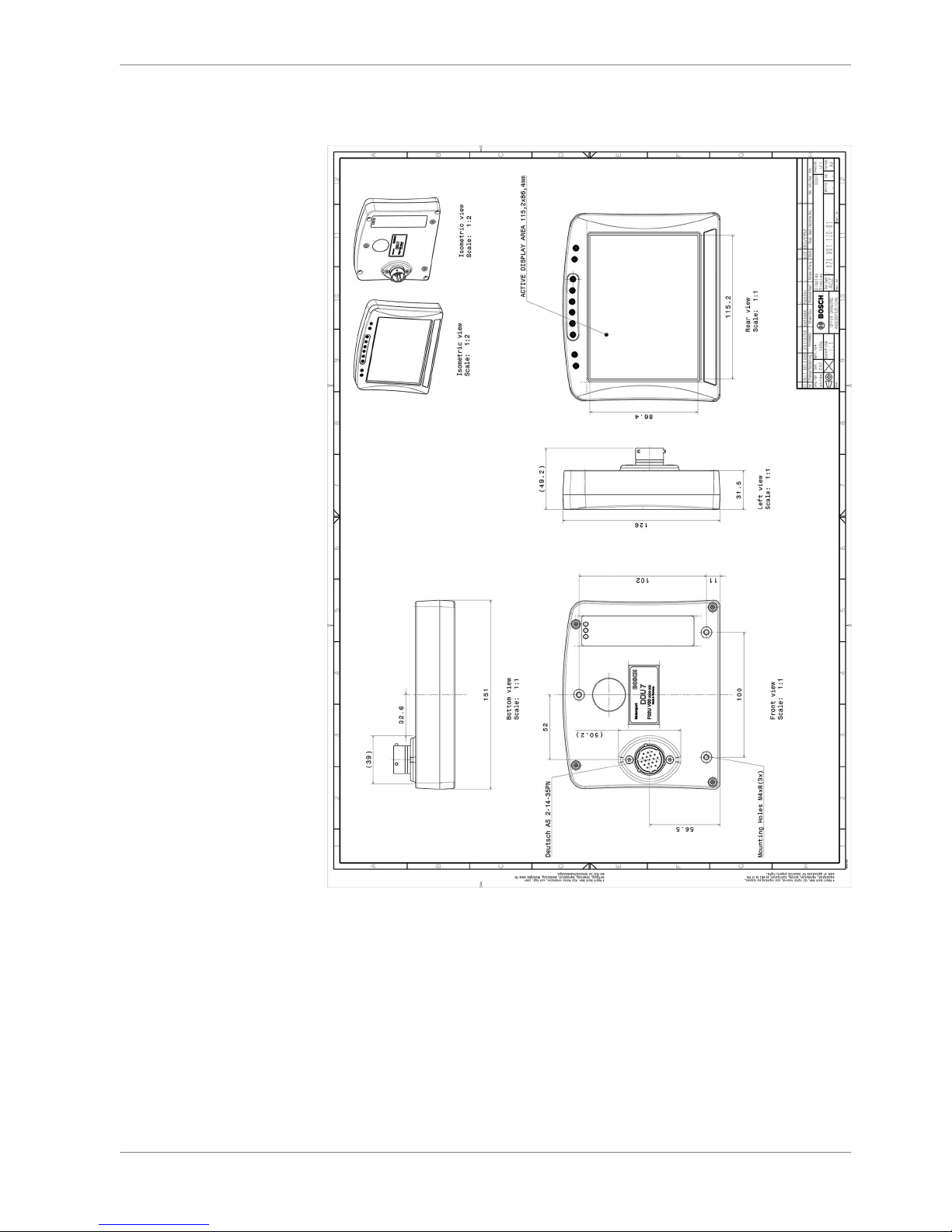
Mechanical Drawing
6
Mechanical Drawing | 6
Bosch Motorsport DDU S2 PLUS Manual 13 / 136
Starting up
Before starting
Install the software required DDU 8 operation. It is developed for Windows
2000/XP/Vista/7.
Following software versions are used in this manual:
▪ DDU 8 setup, configuration and calibration: RaceCon later than 2.5.0.400.
Set up the 100 Mbit Ethernet connection to the DDU 8.
▪ The Ethernet port has ‘cable auto crossover’ functionality
Minimum wiring loom of the Life connector (red):
Pin Description
Pin 1+2+3 12 V supply voltage
Pin 4+5 GND supply voltage
Pin 6 Ethernet Tx+
Pin 7 Ethernet Tx‐
Pin 8 Ethernet Rx+
Pin 9 Ethernet Rx‐
Pin 10 Ethernet Screen
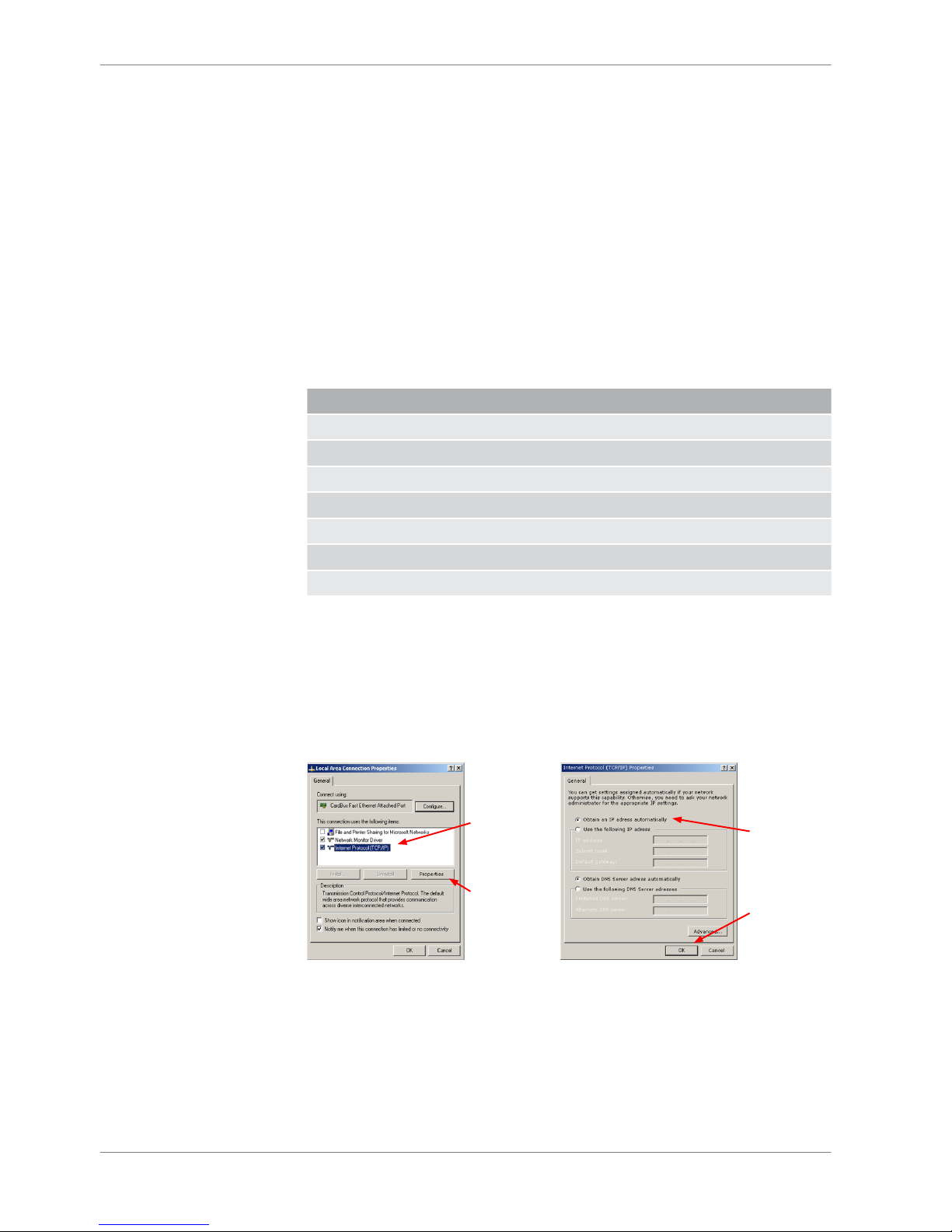
Setting up the network interface
The DDU 8 contains a DHCP server, network addresses can be assigned automat‐
ically to the configuration PC. The IP address of DDU 8 is 10.10.0.208.
1. Switch off the PC’s firewall.
2. Set up the PC’s network interface as shown in the screenshots.
Select
'Internet Protocol
(TCP/IP)'
Click
'Properties'
Select 'Obtain
an IP adress
automatically'
Click 'OK'
when done
Starting the unit
The DDU 8 powers up by turning on the ignition of the car. At startup the DDU 8
will display a Bosch logo.
7
7.1
7.1.1
7.1.2
7 | Starting up
14 / 136 DDU S2 PLUS Manual Bosch Motorsport
After a moment the DDU 8 shows a display element screen.
The ‘Link LED’ at the PC’s network adapter will illuminate. If the LED is off, check
the wiring harness.
About RaceCon
RaceCon is an all integrated software tool for configuration and calibration of
Bosch Motorsport hardware products. It is used to set up, configure and calibrate
the DDU 8.
For better understanding, Bosch Motorsport offers a video tutorial that explains
many functions of RaceCon. The video tutorial is available in the ‘Software Down‐
load’ section of www.bosch‐motorsport.com.
Connecting the Unit to RaceCon
The following screenshot shows an overview of the RaceCon Main Screen with its
areas. All (sub‐) windows are resizable and dockable.
7.1.3
7.1.4
Starting up | 7
Bosch Motorsport DDU S2 PLUS Manual 15 / 136
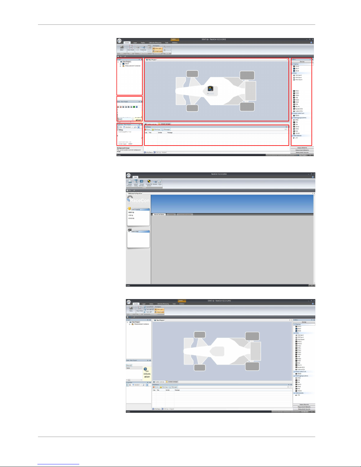
Project
Tree
Data Area
Properties Message Area
Main Area
Toolbox
1. Start the RaceCon software.
2. In the ‘File’ menu select ‘New’ to create a new project.
7 | Starting up
16 / 136 DDU S2 PLUS Manual Bosch Motorsport
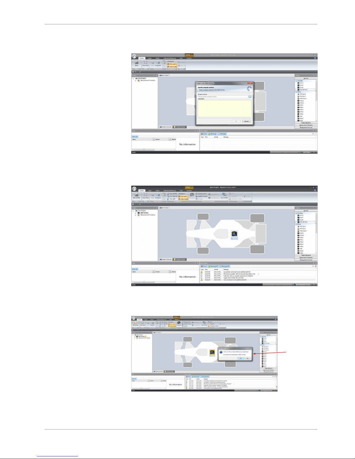
3. In the Toolbox select the DDU 8 and drag it into the Main Area. A pop up
window to specify the DDU 8 program archive appears.
An information shows that the archive is valid or not.
4. Select the program archive delivered with the DDU 8 (.PST file).
5. Click ‘OK’.
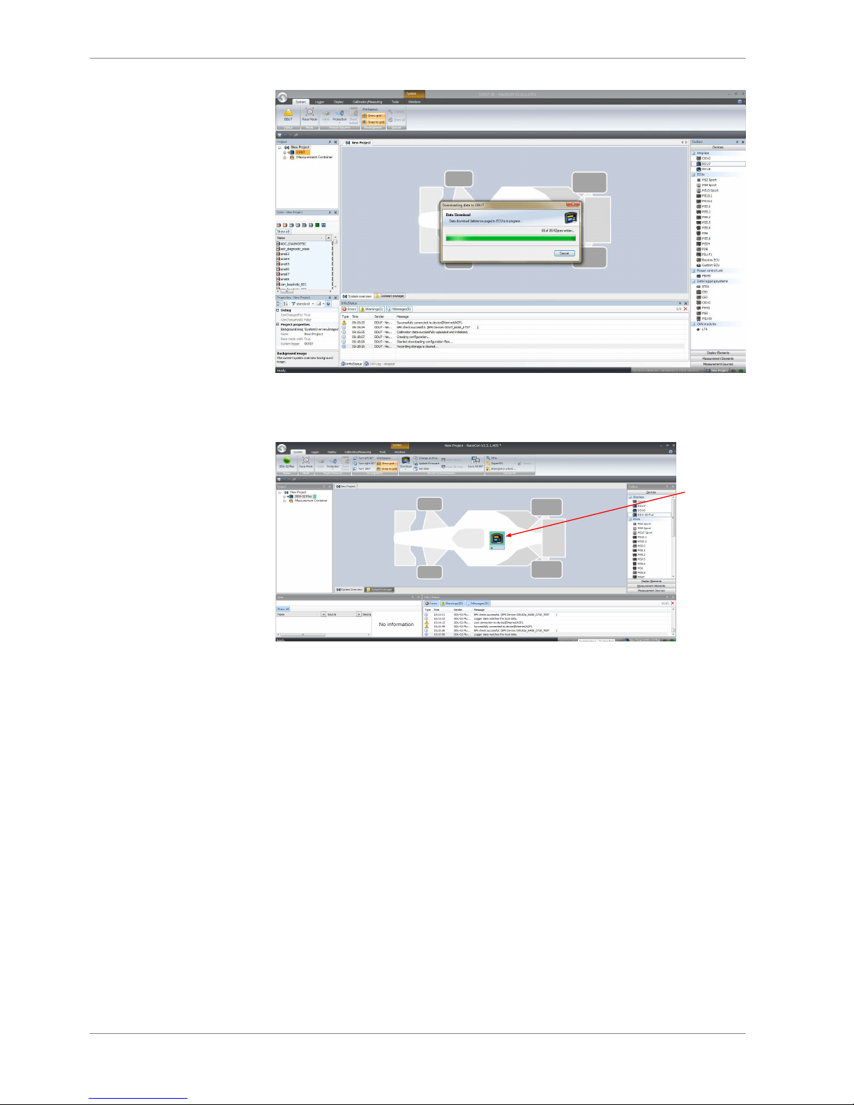
RaceCon detects configuration differences between the DDU 8 and the Race‐
Con project and asks for permission for data download.
6. Click ‘OK’ to proceed.
Successful Ethernet
connection,
DDU 'talks'
to PC
The download starts and the DDU 8 carries out a reset.
Starting up | 7
Bosch Motorsport DDU S2 PLUS Manual 17 / 136
After the reset RaceCon reconnects to the DDU 8. Local configuration on both
the PC and DDU 8 match (Indicated by green background and dot). The DDU 8 is
now connected to RaceCon.
Green background
and dot indicate
matching
configuration
First display configuration (Quick Start)
This chapter explains the configuration of a display element showing the battery
voltage.
See chapter ‘Display element configuration’ for a detailed instruction to config‐
ure display elements.
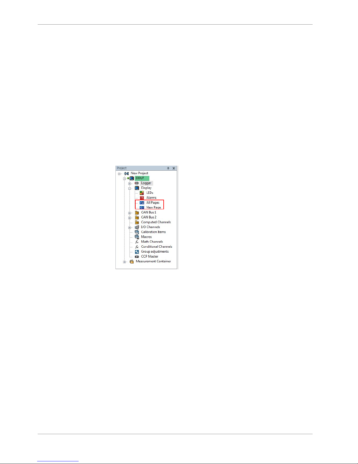
1. Expand the DDU 8 Project Tree by clicking ‘+’.
7.2
7 | Starting up
18 / 136 DDU S2 PLUS Manual Bosch Motorsport
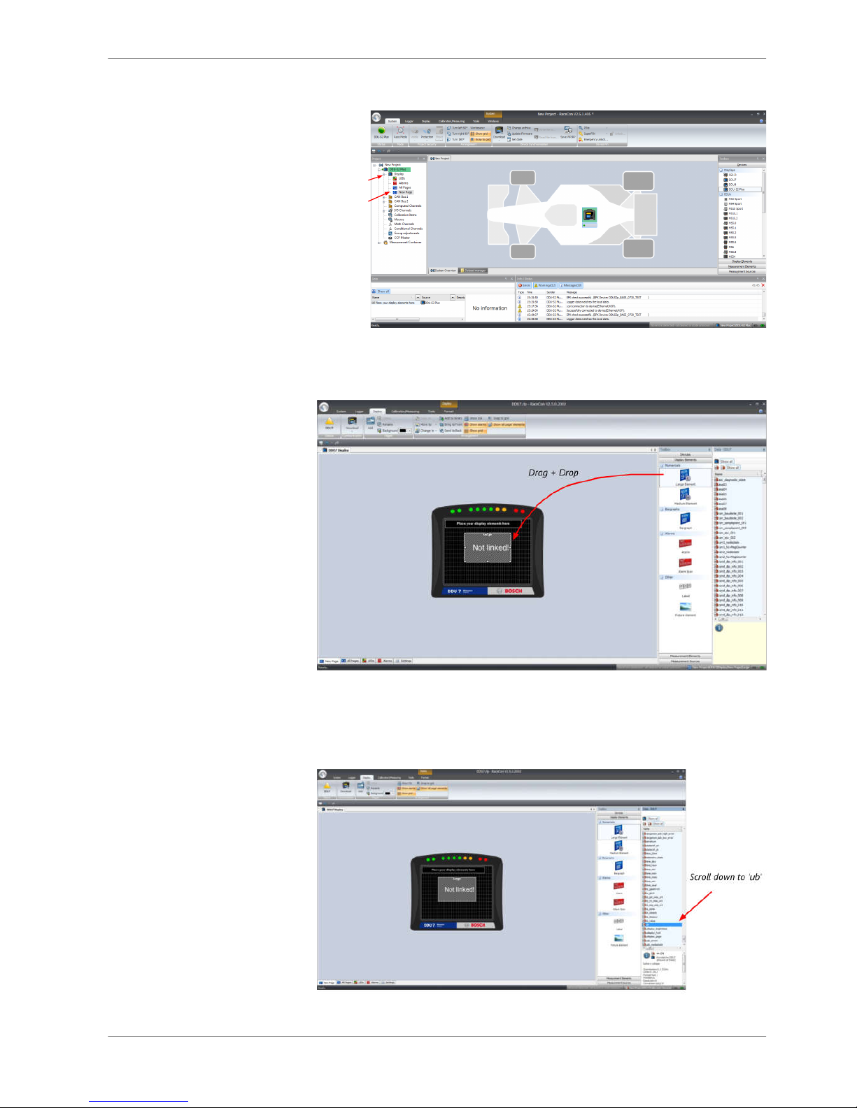
2. Double‐click on ‘New Page’. The DDU 8 display configuration area opens.
Click '+'
Double-click
'New Page'
3. Drag a ‘Large Element’ from the Toolbox and drop it on the display page. A
message in the ‘Large Element’ box shows that it is not linked to a measure‐
ment channel.
4. In the DDU 8 Project Tree, click on ‘DDU 8’ to display the available measure‐
ment channels.
5. In the data window, scroll down to ‘ub’ (measurement channel for battery
voltage).
Starting up | 7
Bosch Motorsport DDU S2 PLUS Manual 19 / 136
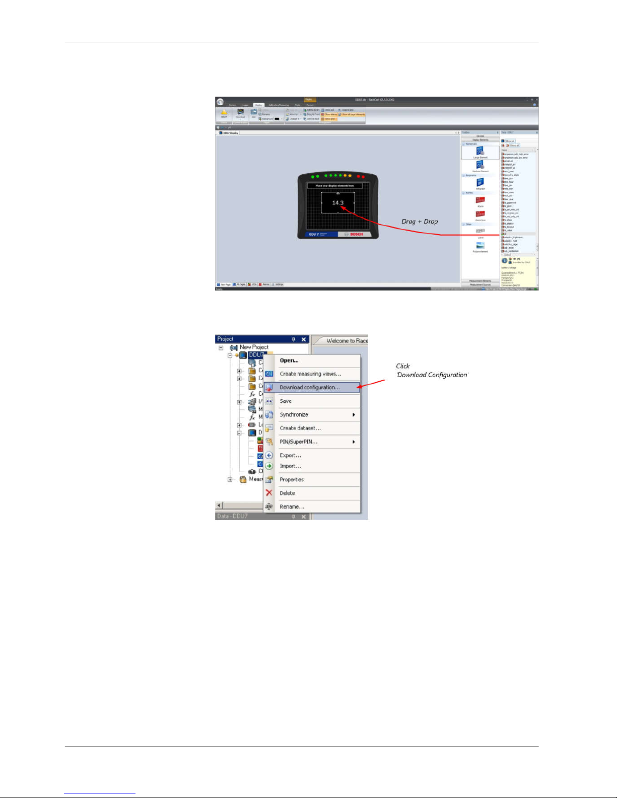
6. Drag the ‘ub’ measurement channel from the Data Area and drop it on the
‘Large Element’.
7. Right‐click on ‘DDU 8’ in the DDU 8 Project Tree and choose ‘Download Con‐
figuration’.
The configurations download starts and the DDU 8 carries out a reset.
7 | Starting up
20 / 136 DDU S2 PLUS Manual Bosch Motorsport
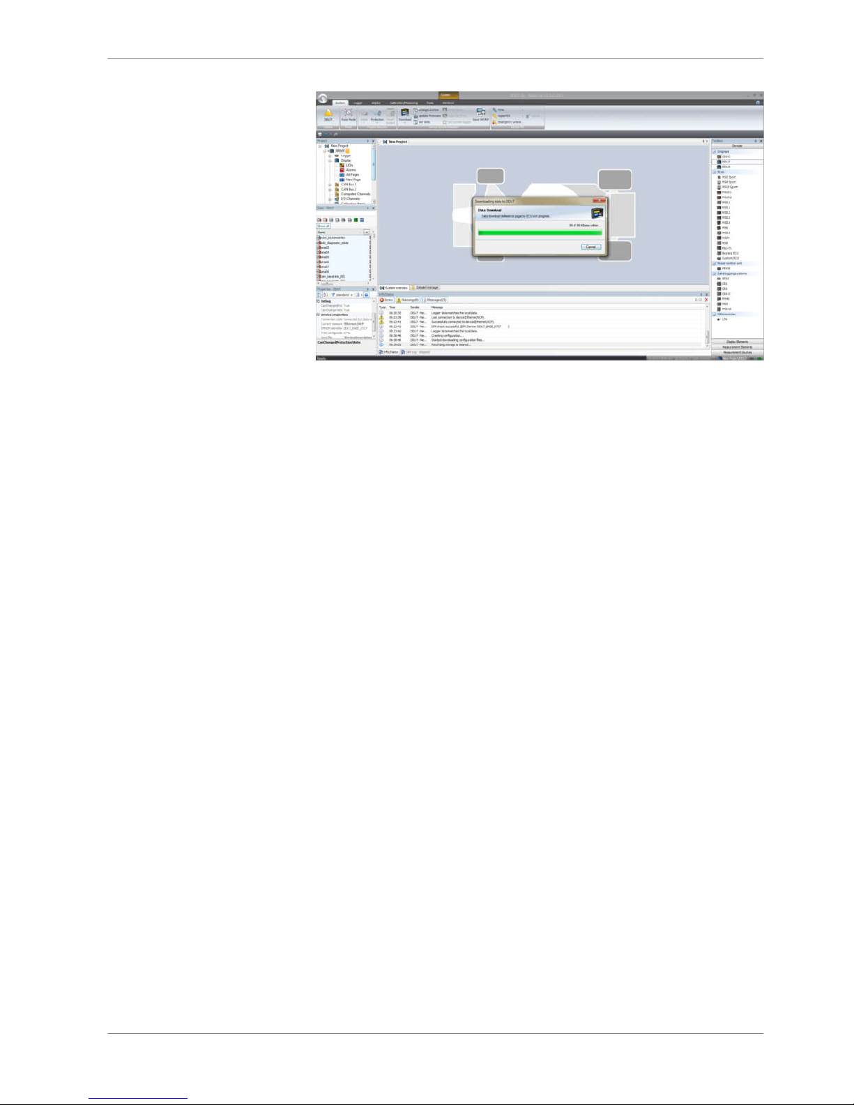
The value of the battery voltage is displayed on the DDU 8.
Starting up | 7
Bosch Motorsport DDU S2 PLUS Manual 21 / 136
Display Configuration
▪ DDU 8 features: 640 x 480 full color TFT display + 10 color LEDs
▪ Display and LEDs are fully configurable
▪ ECU channels, analog channels, and CAN channels can be displayed
▪ Display elements: large numeric, medium numeric, bar graph style, alarm
messages, static elements, image element
▪ DDU 8 supports up to 12 display pages, 6 brightness settings for display and
LEDs
Display page setup
Organizing display pages
▪ All Pages: Display elements placed on this page are displayed on all pages.
Recommended for ‘Alarm’ display elements.
▪ Single Page: Display elements placed on this page are displayed only on this
page.
The priority of display elements placed on ‘All Pages’ is higher than the priority
of display elements placed on single pages.
Example: An Alarm placed on ‘All Pages’ is displayed on all display pages and is
always in front of other display elements.
Adding a new display page
Right‐click on ‘Display’ and click ‘Add Page’ in the menu.
8
8.1
8.1.1
8.1.2
8 | Display Configuration
22 / 136 DDU S2 PLUS Manual Bosch Motorsport
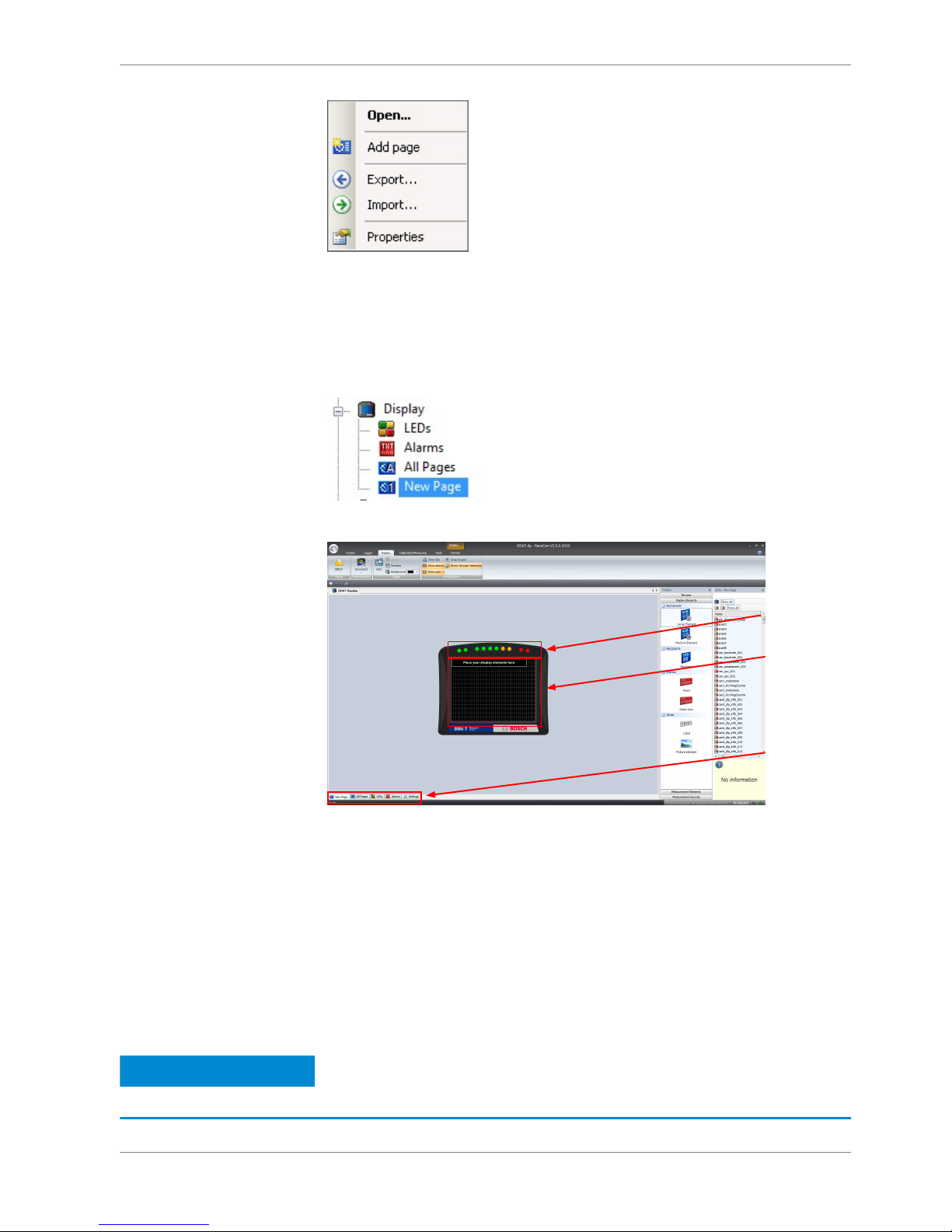
A new empty page opens.
Selecting display page
In the DDU 8 Project Tree, click on ‘DDU 8’, then on ‘Display’ and double‐click on
the page you want to select (example: ‘New Page’).
In the Main Area, a representation of the DDU 8 opens.
Tabs to switch
between different
items / pages
Configurable
LEDs
Display area
Display element configuration
Numeric display element
Adding a numeric display element to display page
The ‘Large Element’ and the ‘Medium Element’ numeric display elements differ in
element and font size. The element and font size can be changed using the Nu‐
meric Wizard.
Notice
In this view the displayed values are random values and do not
show the real values of the measurement channels.
8.1.3
8.2
8.2.1
Display Configuration | 8
Bosch Motorsport DDU S2 PLUS Manual 23 / 136
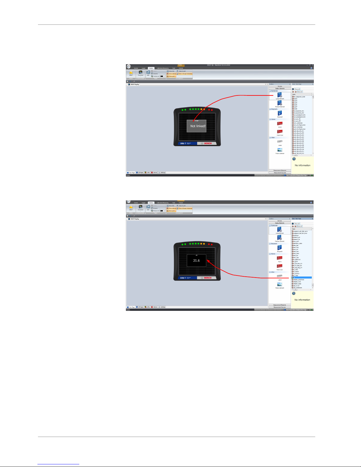
1. Drag a numeric display element from the Toolbox and drop it on the display
page. A message in the numeric element box shows that it is not linked to a
measurement channel.
Drag + Drop
2. Drag a measurement channel from the Data Area and drop it on the numeric
display element.
Drag + Drop
The measurement channel is linked to the numeric display element.
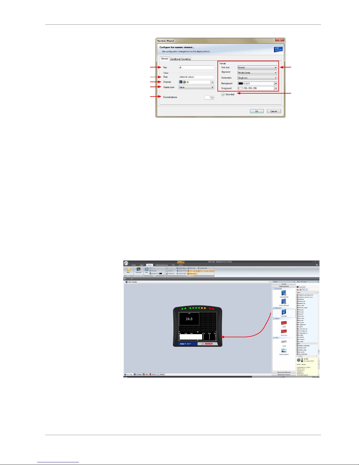
Configuring a numeric display element
1. Double‐click on the numeric display element. The Numeric Wizard window
opens.
8 | Display Configuration
24 / 136 DDU S2 PLUS Manual Bosch Motorsport
a)
b)
c)
d)
e)
f)
g)
a) Enter the title displayed on top of the numeric display element.
b) Enter the text displayed in the middle of the numeric display element. The variable
<channel value> displays the value of the measurement channel.
c) Choose the measurement channel.
d) Choose the type of input data:
- Value
- Gear
- Time (in different formats)
e) Enter the number of decimal places of the measurement channel.
f) Choose the font size, alignment, borderstyle, background and foreground color of the numeric
display element.
g) Click the Extended button to show further options to change the color of the title, border and text
individually.
2. Click ‘OK’ when done.
'Bargraph' display element
Adding a ‘Bargraph’ display element to display page
Drag the ‘Bargraph’ display element from the Toolbox and drop it on the display
page.
Drag + Drop
Configuring a ‘Bargraph’ display element
1. Double‐click on the ‘Bargraph’ display element. The Bargraph Wizard window
opens.
8.2.2
Display Configuration | 8
Bosch Motorsport DDU S2 PLUS Manual 25 / 136
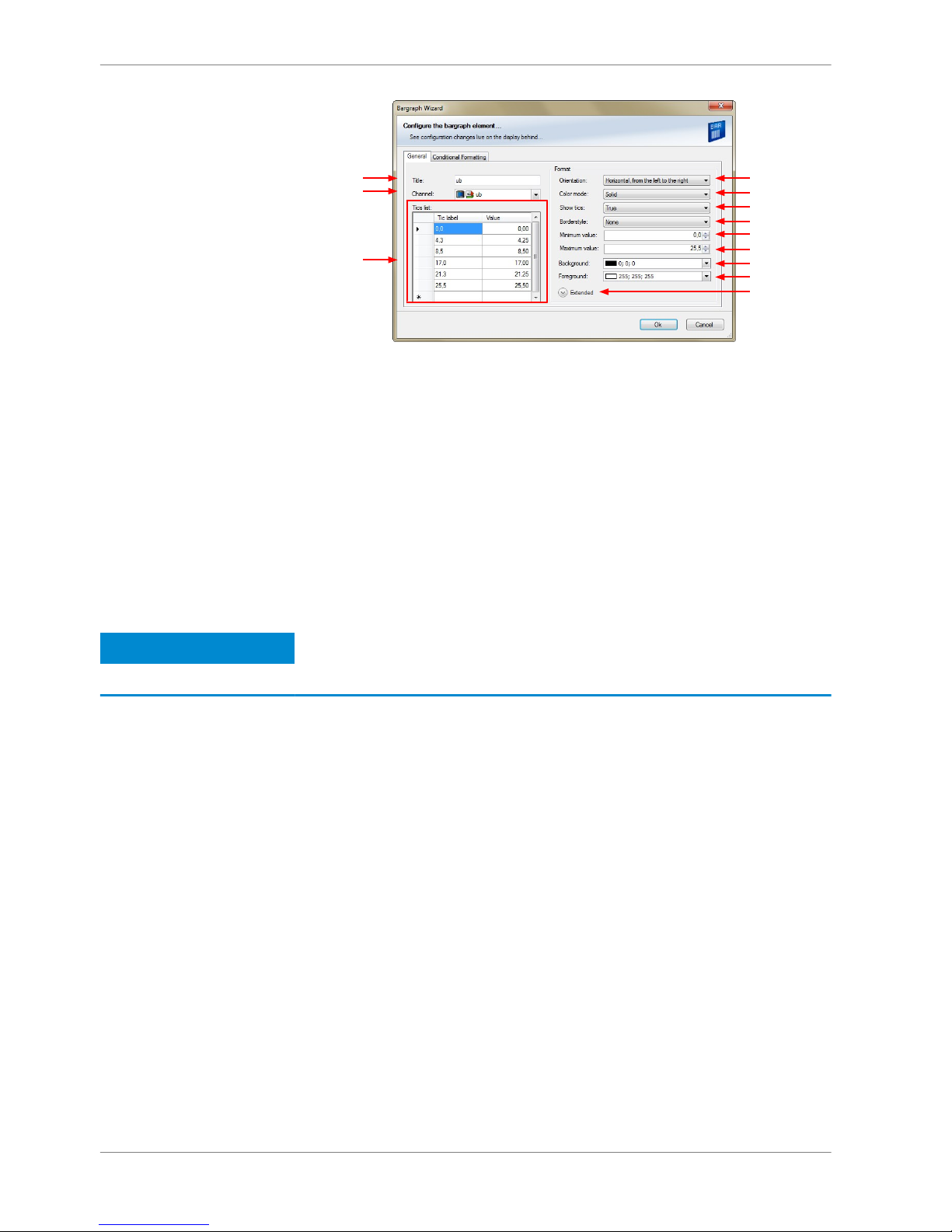
a)
b)
c)
d)
e)
f)
g)
h)
i)
j)
k)
l)
a) Enter the title displayed on top of the 'Bargraph' display element.
b) Choose the measurement channel.
c) Define the tick text corresponding with the physical value. You can add more tix labels by entering values
in the row labeled with *.
d) Choose the orientation of the Bargraph (horizontal or vertical).
e) Choose the color mode of the Bargraph:
- Solid: The whole Bargraph and tics are colored in one color
- Stacked: The Bargraph is subdivided in segments with different colors. The colors are set in the tab
'Conditional Formatting'. For details, see chapter 'Conditional Formatting'.
f) Define if ticks and numbers are shown.
g) Choose the style of the border lines.
h) Enter the physical value where the Bargraph begins.
i) Enter the physical value where the Bargraph ends.
j) Choose the background color of the Bargraph.
k) Choose the foreground color of the Bargraph.
l) Click the Extended button to show further options to change the color of the title, border and text
individually.
2. Click ‘OK’ when done.
Notice
The tab ‘Conditional Formatting’ is explained in chapter ‘Con‐
ditional formatting’.
'Alarm' display element
The ‘Alarm’ display element displays a warning message in case of a defined con‐
dition becoming ‘true’. In case of a condition becoming ‘false’, the ‘Alarm’ display
element is not shown.
Two types of ‘Alarm’ display elements are available:
▪ Alarm: An alarm displaying a defined text
▪ Alarm Icon: An alarm displaying a defined image (e.g. a warning triangle)
8.2.3
8 | Display Configuration
26 / 136 DDU S2 PLUS Manual Bosch Motorsport
Adding an ‘Alarm’ display element to display page
Drag an ‘Alarm’ element from the Toolbox and drop it on the display page.
Drag + Drop
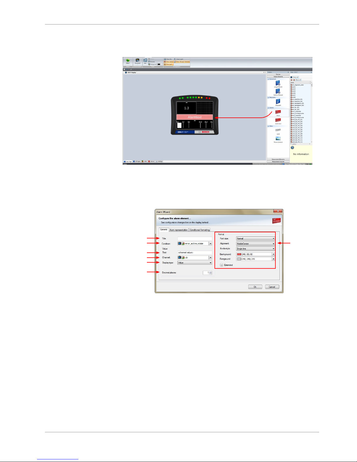
Configuring an ‘Alarm’ (text) display element
1. Double‐click on the ‘Alarm’ display element. The Alarm Wizard window
opens.
a)
b)
c)
d)
e)
f)
g)
a) Enter the title displayed on top of the 'Alarm' display element.
b) Choose the condition when the alarm will be activated:
- Create a condition using the Condition Creator. For more information see chapter 'Creating a new
condition channel'
- Choose an existing condition.
The Alarm is displayed if function is 'TRUE', i.e. result of the calculation is >0.
c) Enter the alarm message displayed in the middle of the 'Alarm' display element. Enter the variable
<channel value> to display the value of the measurement channel.
d) Choose the measurement channel.
e) Choose the type of input data:
- Value
- Gear
- Time (in different formats)
f) Enter the number of decimal places of the measurement channel.
g) Choose the font size, alignment, borderstyle, background and foreground color of the 'Alarm'
dislay element.
2. Switch to the tab ‘Alarm representation’.
Display Configuration | 8
Bosch Motorsport DDU S2 PLUS Manual 27 / 136
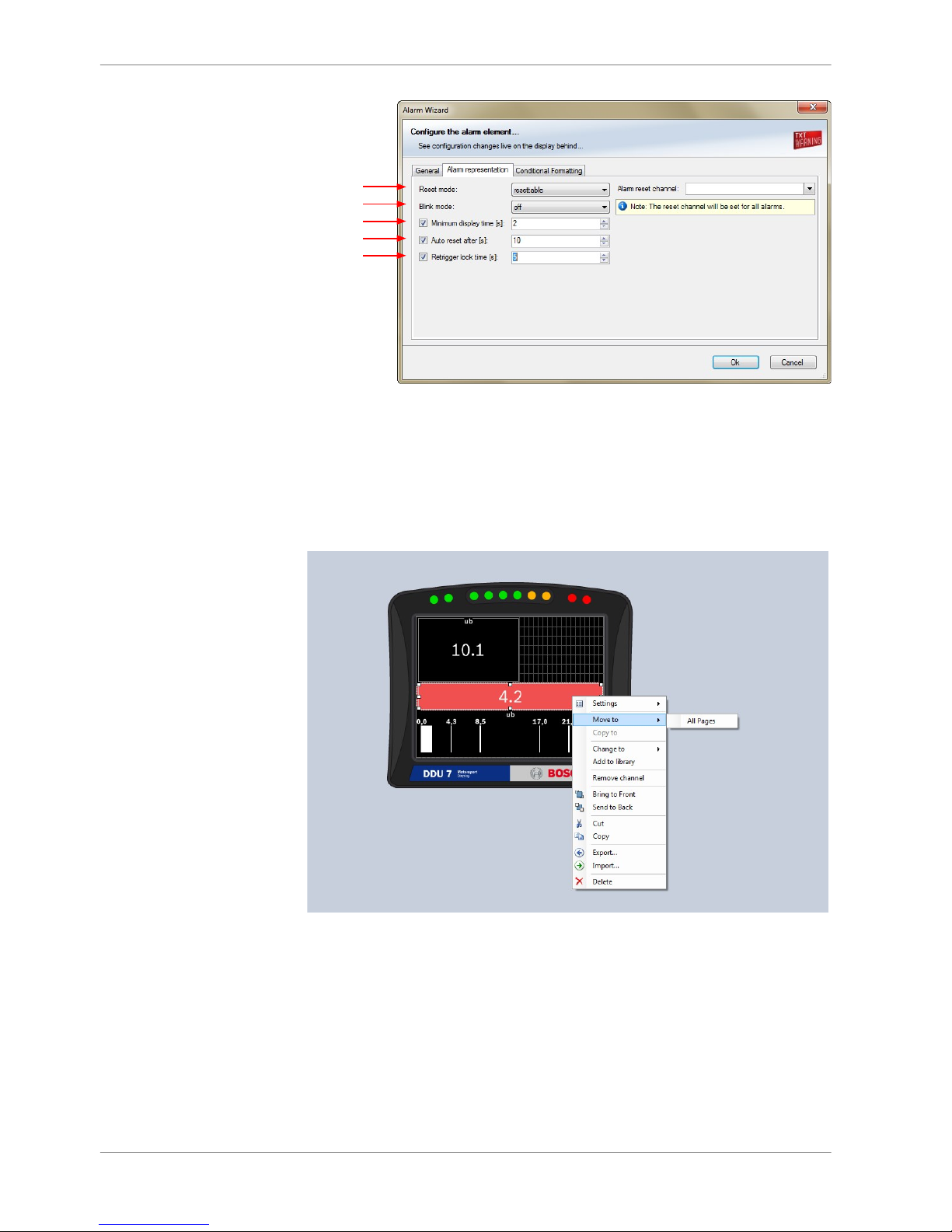
a)
b)
c)
d)
e)
a) Choose if the alarm can be reset or not.
b) Choose if the alarm blinks slowly, fast or does not blink.
c) Enter the minimum time the Alarm display element is displayed if an alarm is triggered.
d) Enter the time until the Alarm resets automatically after the minimum display time entered in c).
Only possible if Alarm is resettable.
e) Enter the time until the Alarm can appear again after a reset.
3. Click ‘OK’ when done.
4. Copy alarm to all display pages by clicking ‘Move to’ ‐> ‘All Pages’.
8 | Display Configuration
28 / 136 DDU S2 PLUS Manual Bosch Motorsport

Configuring an ‘Alarm Icon’ (image) display element
Drag + Drop
1. Double‐click on the ‘Alarm Icon’ display element.
The Alarm Icon Wizard window opens.
a)
b)
c)
d)
e)
a) Select the image from the hard drive that is shown in case of an alarm.
b) Choose the condition when the alarm will be activated:
- Create a condition using the Condition Creator. For more information see chapter
'Creating a new condition channel'
- Choose an existing condition
The 'Alarm Icon' is displayed if function is 'TRUE'; i.e. result of the calculation is >0.
c) Enable the checkbox if you want to define parts of the image as transparent.
d) Select the basic transparent color key. This means that any pixel of the amage near (depending of the
tolerance value) to this color gets transparent.
e) Select a tolerance in percent to define parts of the mage as transparent.
2. Switch to the tab ‘Alarm representation’. It is configured in the same way as
the ‘Alarm’ text display element.
3. Click ‘OK’ when done.
Notice
If several active alarms in the display overlap, each alarm is in
the foreground for 2 seconds.
Display Configuration | 8
Bosch Motorsport DDU S2 PLUS Manual 29 / 136
Other display elements
Two types of other display elements are available:
▪ Label: A label displaying a specified text
▪ Picture element: An element displaying a static picture (e.g. temperature
warning)
Adding a Label or picture display element to display page
Drag the Label or picture display element from the Toolbox and drop it on the
display page.
Drag + Drop
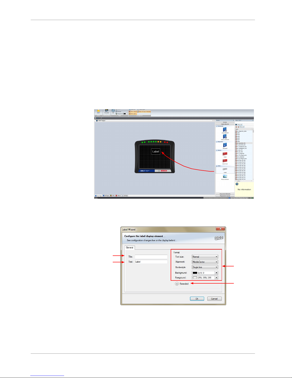
Configuring a Label display element
1. Double‐click on the Label display element. The Label Wizard window opens.
a)
b)
c)
d)
a) Enter the title displayed on top of the Label display element.
b) Enter the text displayed in the middle of the Label display element.
c) Choose the font size, alignment, borderstyle, background and foreground color of the Label
display element.
d) Click the Extended button to show further options to change the color of the title, border and
text individually.
2. Click ‘OK’ when done.
8.2.4
8 | Display Configuration
30 / 136 DDU S2 PLUS Manual Bosch Motorsport
 Loading...