

Bosch CS 200 Installation Instructions For Installers
6720850722 (2015/06)
Installation instructions for installers
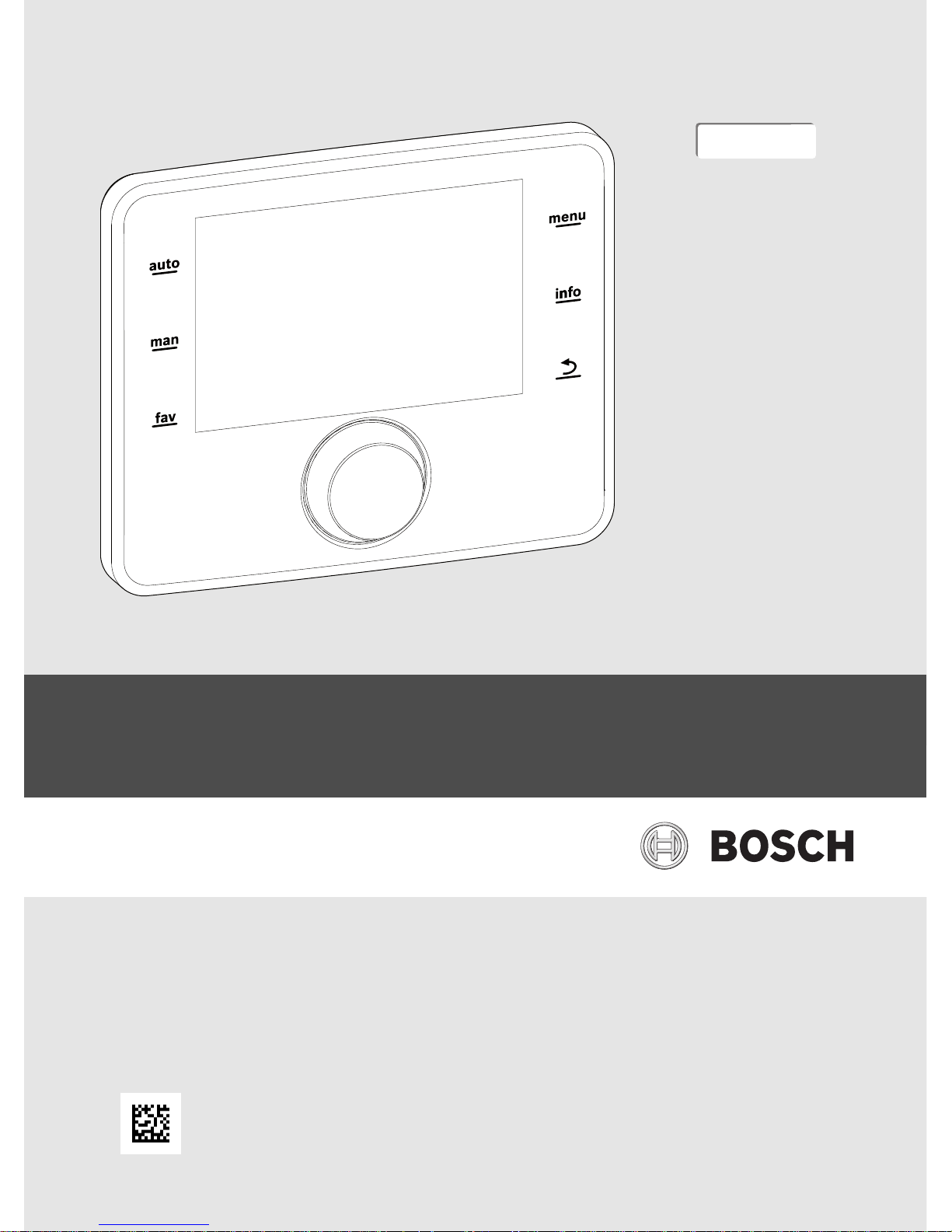
Solar controller
CS200
0010005426-001
EMS 2
6720850722 (2015/06) CS200
2 | Table of contents
Table of contents
1 Key to symbols and safety instructions . . . . . . . . . . . . 3
1.1 Explanation of symbols . . . . . . . . . . . . . . . . . . . . . . 3
1.2 General safety instructions . . . . . . . . . . . . . . . . . . . 3
2 Product Description . . . . . . . . . . . . . . . . . . . . . . . . . . . . 4
2.1 Product description . . . . . . . . . . . . . . . . . . . . . . . . . 4
2.2 Important information on use . . . . . . . . . . . . . . . . . 4
2.3 Declaration of Conformity . . . . . . . . . . . . . . . . . . . . 4
2.4 Scope of delivery . . . . . . . . . . . . . . . . . . . . . . . . . . . 4
2.5 Technical specifications . . . . . . . . . . . . . . . . . . . . . 4
2.6 Temperature sensor characteristics . . . . . . . . . . . . 5
2.7 Additional accessories. . . . . . . . . . . . . . . . . . . . . . . 5
2.8 Disposal . . . . . . . . . . . . . . . . . . . . . . . . . . . . . . . . . . 5
3 Installation . . . . . . . . . . . . . . . . . . . . . . . . . . . . . . . . . . . . 5
3.1 Types of installation . . . . . . . . . . . . . . . . . . . . . . . . . 5
3.2 Installation location of the solar controller. . . . . . . 5
3.3 Installation in the reference room . . . . . . . . . . . . . . 5
3.4 Electrical connection . . . . . . . . . . . . . . . . . . . . . . . . 6
3.5 Fitting/Removing the controller . . . . . . . . . . . . . . . 6
4 Basic principles of operation . . . . . . . . . . . . . . . . . . . . . 7
4.1 Overview of the control elements . . . . . . . . . . . . . . 7
4.2 Overview of the symbols in the display. . . . . . . . . . 7
4.3 Operating the service menu . . . . . . . . . . . . . . . . . . 8
4.4 Overview of the service menu . . . . . . . . . . . . . . . . . 8
5 Commissioning. . . . . . . . . . . . . . . . . . . . . . . . . . . . . . . . . 8
5.1 Overview of the commissioning steps . . . . . . . . . . 9
5.2 General commissioning of the solar controller. . . . 9
5.3 System commissioning with the configuration
wizard . . . . . . . . . . . . . . . . . . . . . . . . . . . . . . . . . . . . 9
5.3.1 Commissioning the solar heating system. . . . . . . . 9
5.3.2 Commissioning the freshwater system . . . . . . . . 10
5.3.3 Commissioning the transfer station . . . . . . . . . . . 11
5.4 Additional settings at commissioning. . . . . . . . . . 11
5.5 Performing function tests . . . . . . . . . . . . . . . . . . . 11
5.6 Check monitored values . . . . . . . . . . . . . . . . . . . . 11
5.7 System handover . . . . . . . . . . . . . . . . . . . . . . . . . . 11
6 Shutdown / switching off . . . . . . . . . . . . . . . . . . . . . . . 11
7 Service menu . . . . . . . . . . . . . . . . . . . . . . . . . . . . . . . . . 11
7.1 Solar system settings. . . . . . . . . . . . . . . . . . . . . . . 13
7.2 Settings for transfer systems . . . . . . . . . . . . . . . . 13
7.3 Settings for freshwater systems . . . . . . . . . . . . . . 13
7.4 Diagnosis . . . . . . . . . . . . . . . . . . . . . . . . . . . . . . . . 14
7.4.1 Function tests . . . . . . . . . . . . . . . . . . . . . . . . . . . . 14
7.4.2 Monitored values. . . . . . . . . . . . . . . . . . . . . . . . . . 14
7.4.3 Fault displays. . . . . . . . . . . . . . . . . . . . . . . . . . . . . 14
7.4.4 System information. . . . . . . . . . . . . . . . . . . . . . . . 14
7.4.5 Maintenance . . . . . . . . . . . . . . . . . . . . . . . . . . . . . 14
7.4.6 Reset . . . . . . . . . . . . . . . . . . . . . . . . . . . . . . . . . . . 15
7.4.7 Calibration . . . . . . . . . . . . . . . . . . . . . . . . . . . . . . . 15
8 Thermal disinfection . . . . . . . . . . . . . . . . . . . . . . . . . . . 15
9 Troubleshooting . . . . . . . . . . . . . . . . . . . . . . . . . . . . . . . 15
10 Environmental protection and disposal . . . . . . . . . . . 16
6720850722 (2015/06)CS200
Key to symbols and safety instructions | 3
1 Key to symbols and safety instructions
1.1 Explanation of symbols
Warning symbols
Keywords at the start of a warning indicate the type and
seriousness of the ensuing risk if measures to prevent the risk
are not taken.
The following keywords are defined and can be used in this
document:
DANGER:
DANGER indicates a situation that will result in severe injury or
death.
WARNING:
WARNING indicates a situation that could result in severe
injury or death.
CAUTION:
CAUTION indicates a situation that could result in minor to
medium injury.
NOTICE:
NOTICE indicates a situation that could result in damage to
property or equipment.
Important information
The info symbol indicates important information where there is
no risk to people or property.
Additional symbols
Table 1
1.2 General safety instructions
These installation instructions are intended for plumbers,
heating engineers and electricians.
▶ Read the installation instructions (heat sources, modules,
etc.) before installation.
▶ Observe the safety instructions and warnings.
▶ Observe national and regional regulations, technical rules
and guidelines.
▶ Record all work carried out.
H Determined use
▶ Only use the product to control solar heating systems in
domestic or light commercial applications.
Any other use is considered inappropriate. We take no
responsibility for damage caused through incorrect use.
H Installation, commissioning and maintenance
Installation, commissioning and maintenance must only be
carried out by a competent person.
▶ Never install the product in wet rooms.
▶ Only use genuine spare parts.
H Electrical work
Electrical work must only be carried out by a qualified
electrician.
▶ Before starting electrical work:
– Isolate the mains electrical supply and secure against
reconnection.
– Using suitable means, test that the mains voltage is
disconnected.
▶ Never connect the product to mains voltage.
▶ Also observe the connection diagrams of other system
components.
H Handover to the user
When handing over the solar heating system, instruct the user
in its operation and operating conditions.
▶ Explain the operation - with particular emphasis on all
safety-related actions.
▶ Explain that conversions and repairs must only be carried
out by a competent person.
▶ Point out the need for inspections and maintenance for safe
and optimal operation.
▶ The installation and operating instructions must be given to
the user for safekeeping.
H Damage caused by frost
The solar system can freeze if it is switched off:
▶ Observe the notices regarding frost protection.
Symbol Meaning
▶ a step in an action sequence
a reference to a related part in the document
• a list entry
– a list entry (second level)
6720850722 (2015/06) CS200
4 | Product Description
▶ Due to the additional functions, e.g. DHW heating or pump
anti-seizure protection, the system should always be left
on.
▶ Correct any faults immediately.
2 Product Description
2.1 Product description
• The CS 200 must be used in conjunction with the
MS 200 to control a Solar heating system, in certain
cases an MS 100 may also be combined.
• After operating for 90 minutes, the solar controller has a
power reserve of at least 8 hours. If the power failure lasts
longer than the power reserve, the time and date will be
deleted. All other settings are saved.
• The functional scope and thus the menu structure of the
solar controller are determined by the structure of the
system. These instructions describe the maximum
functional scope of the equipment. Your attention is drawn
to the importance of the system structure in the relevant
places. The adjustment ranges and default settings may
differ from the information in these instructions.
2.2 Important information on use
CAUTION:
Risk of injury through scalding!
If the DHW temperature is set to > 60 °C, discharging unmixed
domestic hot water can lead to serious scalding.
▶ Set the temperature for normal operation to < 60 °C.
▶ Do not discharge domestic hot water unmixed.
▶ Install a mixer.
• Only products from Bosch may be used within the BUS
system.
• The installation room must be appropriate for IP20 rating.
2.3 Declaration of Conformity
The design and operation of this product comply
with European Directives and the supplementary
national requirements. Conformity has been
demonstrated by the CE marking .
You can ask for a copy of the Declaration of Conformity for this
product. Please refer to the contact address on the back cover
of these instructions.
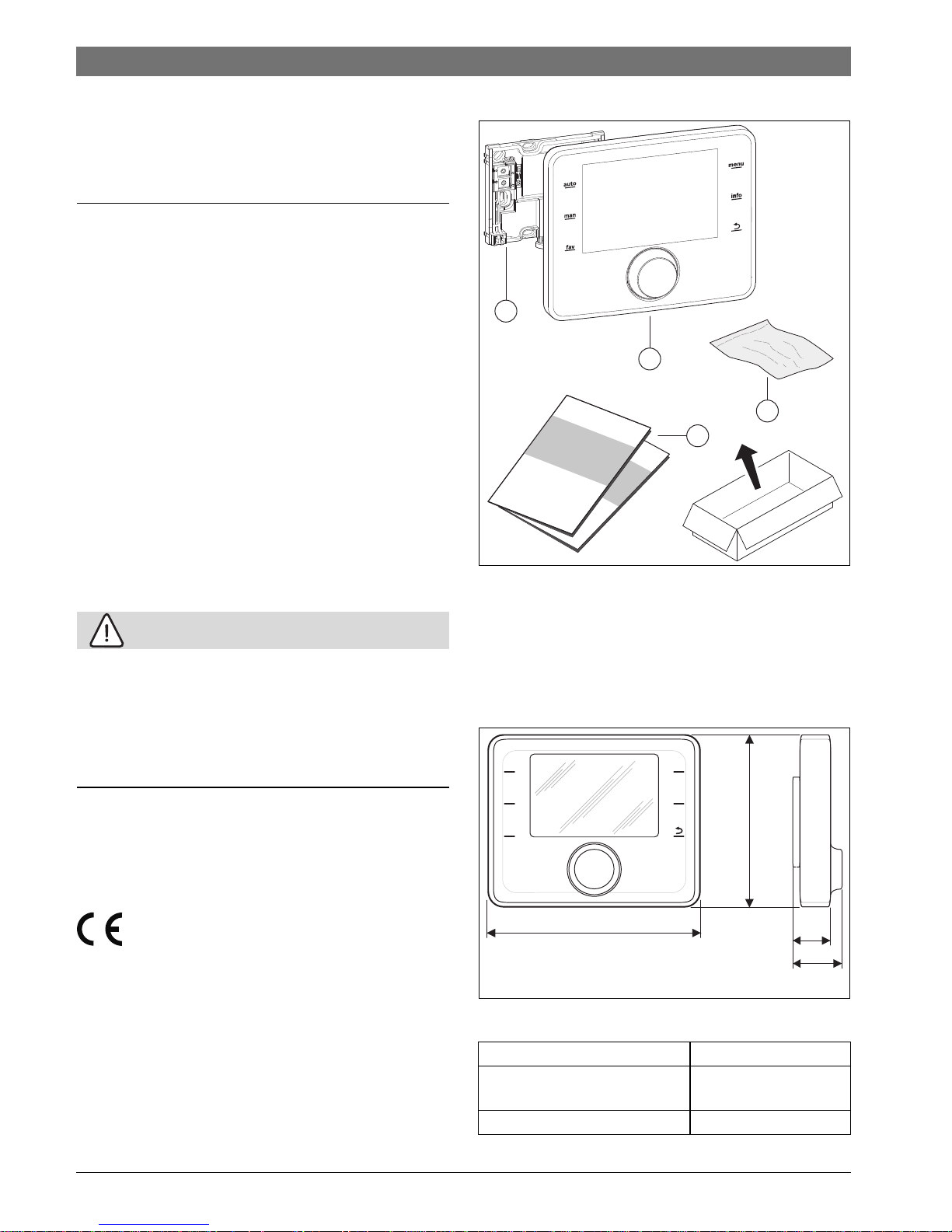
2.4 Scope of delivery
Fig. 1 Scope of delivery
[1] Wall-mounting plate
[2] Solar controller
[3] Installation material
[4] Technical documentation
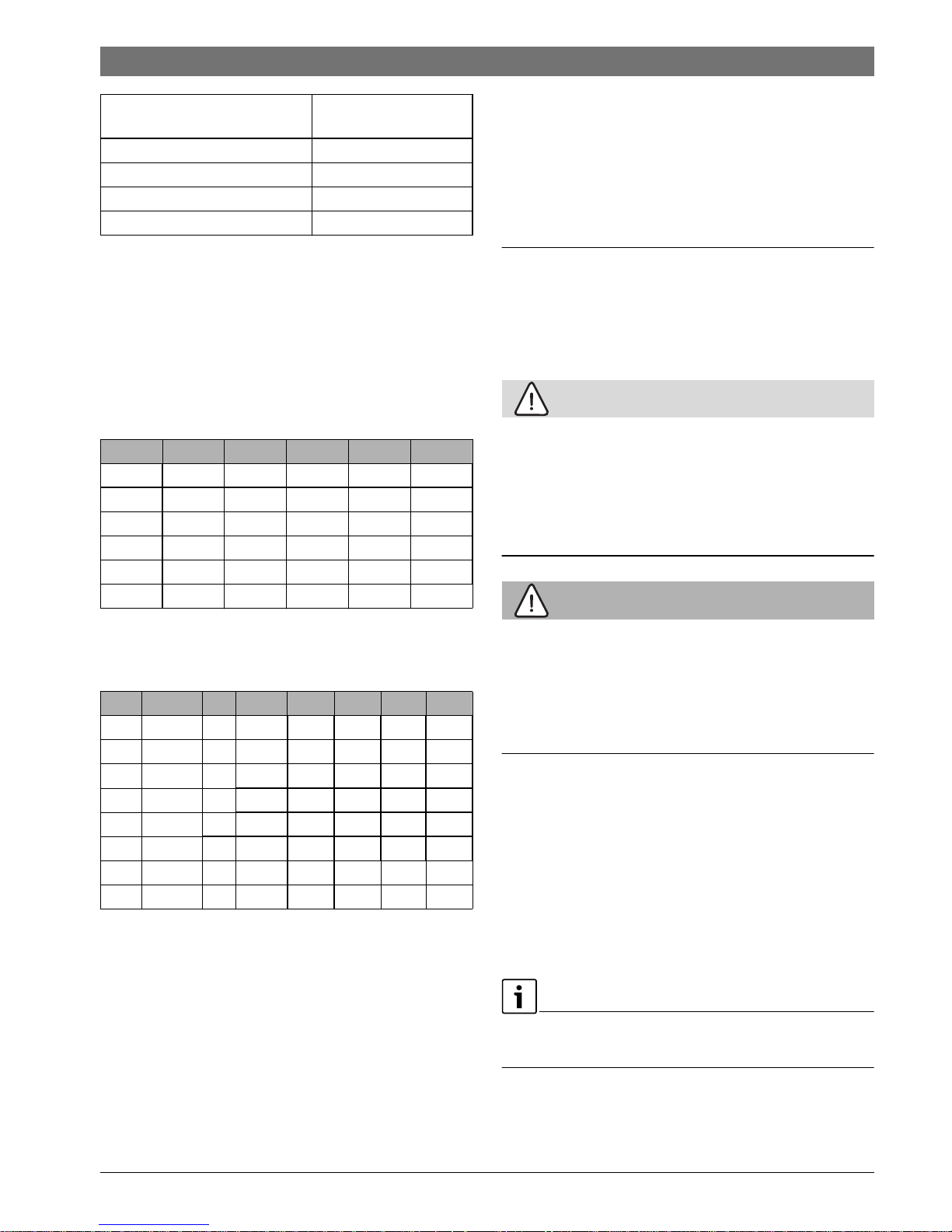
2.5 Technical specifications
Fig. 2 Dimensions in mm
Scope of delivery Chapter 2.4, page 4
Dimensions 150 × 90 × 25 mm
( Fig. 2)
Nominal voltage 10 - 24 V DC
0010005428-001
i
i
1
4
2
3
0010005429-001
auto
man
fav
menu
info
123
25
32
101
6720850722 (2015/06)CS200
Installation | 5
Table 2 Technical specifications
2.6 Temperature sensor characteristics
When measuring temperature sensors, observe the following
requirements:
• Isolate the system before measuring.
• Measure the resistance at the cable ends.
• The resistance values represent average values and are
subject to tolerances.
Table 3 Temperature sensor measurements (all temperature
sensors in solar system except collector temperature
sensors)
Table 4 Collector temperature sensor measurements
2.7 Additional accessories
For precise information regarding suitable accessories, refer to
the manufacturer's product literature.
Function modules and user interfaces of the control system
EMS 2:
• MS 100: Module for solar system or freshwater station
• MS 200: Module for extended solar systems or transfer
system.
2.8 Disposal
▶ Dispose of packaging in an environmentally responsible
manner.
▶ When replacing assemblies or components, dispose of the
old assemblies or components in an environmentally
responsible manner.
3 Installation
The detailed system schematics for installation of the hydraulic
assemblies and components and the associated control
devices can be found in the technical guides or tender
specifications.
CAUTION:
Risk of injury through scalding!
If the DHW temperature is set to > 60 °C, discharging unmixed
domestic hot water can lead to serious scalding.
▶ Set the temperature for normal operation to < 60 °C.
▶ Do not discharge domestic hot water unmixed.
▶ Install a mixer.
WARNING:
Risk to life from electric shock!
Touching live parts can result in an electric shock.
▶ Before installing accessories: Disconnect the power supply
to the heat source, building management system and any
other BUS nodes (all poles) and secure against
unauthorised or accidental reconnection.
3.1 Types of installation
The installation of the solar controller depends on its use and
the solar heating system design ( Chapter 2, page 4).
3.2 Installation location of the solar controller
For direct and easily accessible operation we recommend the
installation of the solar controller in the living space.
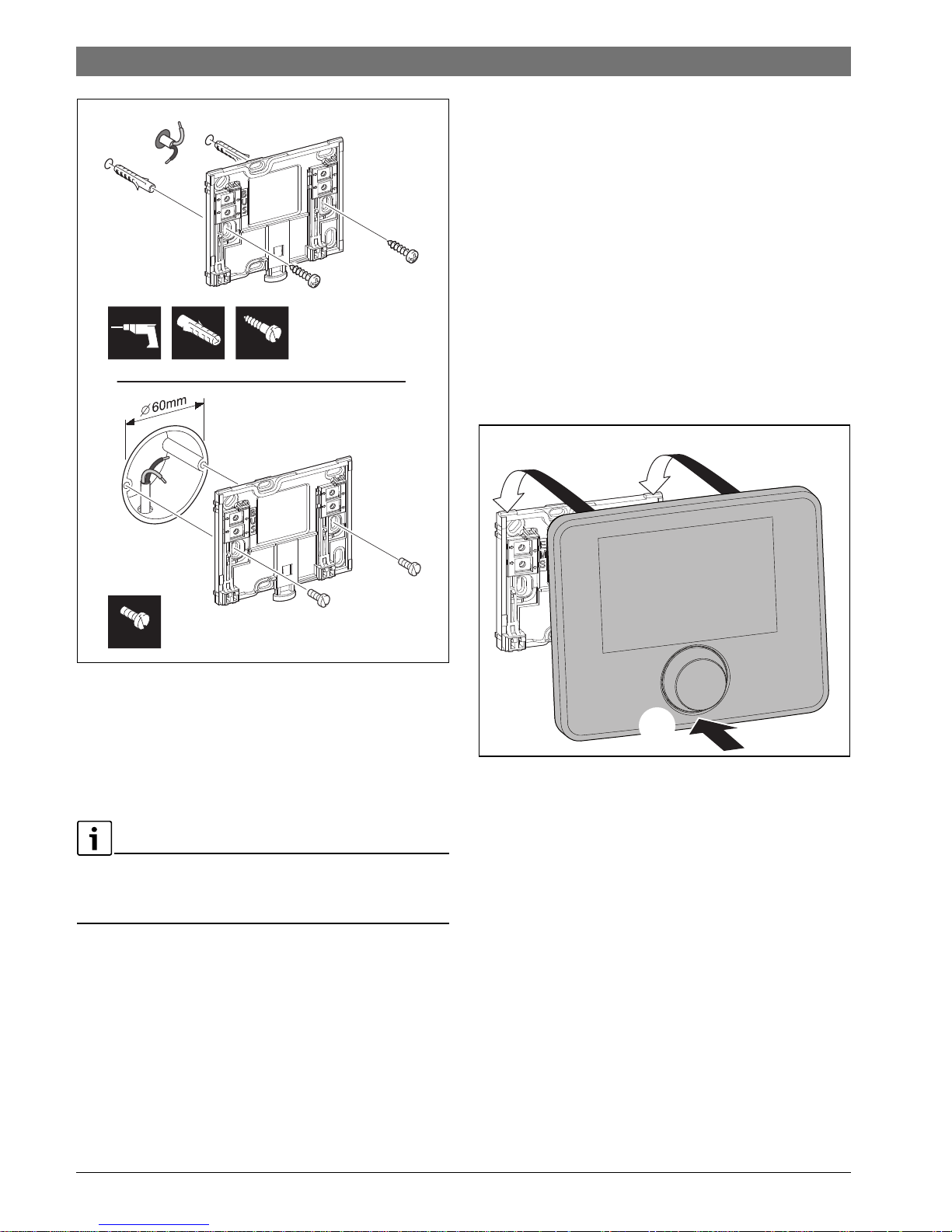
3.3 Installation in the reference room
The installation surface on the wall must be flat.
▶ Install wall-mounting plate ( Fig. 3).
Rated power (excluding
illumination)
9 mA
BUS interface EMS 2
Permitted ambient temp. 0 °C to 50 °C
Protection class III
IP rating IP20
°C °C °C
20 14772 50 4608 80 1704
25 12000 55 3856 85 1464
30 9786 60 3243 90 1262
35 8047 65 2744 95 1093
40 6653 70 2332 100 950
45 5523 75 1990 – –
°C °C °C °C
– 30 364900 25 20000 80 2492 150 364
– 20 198400 30 16090 90 1816 160 290
– 10 112400 35 12800 95 1500 170 233
0 66050 40 10610 100 1344 180 189
5 50000 50 7166 110 1009 190 155
10 40030 60 4943 120 768 200 127
15 32000 70 3478 130 592 – –
20 25030 75 2900 140 461 – –
6720850722 (2015/06) CS200
6 | Installation
Fig. 3 Installation of wall-mounting plate
BUS BUS interface connection
3.4 Electrical connection
Power is supplied to the solar controller via the BUS cable.
The wires are insensitive to polarity.
If the maximum total length of the BUS interfaces between all
BUS nodes is exceeded or the BUS system has a ring structure,
commissioning of the system is not possible.
Maximum total length of BUS interfaces:
• 100 m at 0.50 mm
2
conductor cross-section
• 300 m at 1.50 mm
2
conductor cross-section.
▶ If several BUS nodes are installed, maintain a minimum
clearance of 100 mm between the individual BUS nodes.
▶ If several BUS nodes are installed, connect the BUS nodes
in series or in a star pattern.
▶ To avoid inductive interference: Make sure all low-voltage
cables are routed separately from mains voltage cables
(min. clearance 100 mm).
▶ In the case of external inductive interferences (e.g. from
photovoltaic systems), use shielded cables (e.g. LIYCY)
and earth the shield on one side. The shield should be
connected to the building's earthing system, e.g. to a free
earth conductor terminal or water pipes, and not to the
grounded terminal in the module.
▶ Make a BUS interface to the solar module.
3.5 Fitting/Removing the controller
Fitting the solar controller
▶ Hook in the solar controller at the top.
▶ Click in the solar controller at the bottom.
Fig. 4 Fitting the solar controller
Removing the solar controller
▶ Press the button on the underside of the mounting plate.
▶ Pull the bottom of the solar controller away from the plate.
0010007506-001
6 mm 3.5 mm6 mm
3.5 mm
0010005430-002
1.
1.
2.
 Loading...