

Page 1
CS
550/150RC
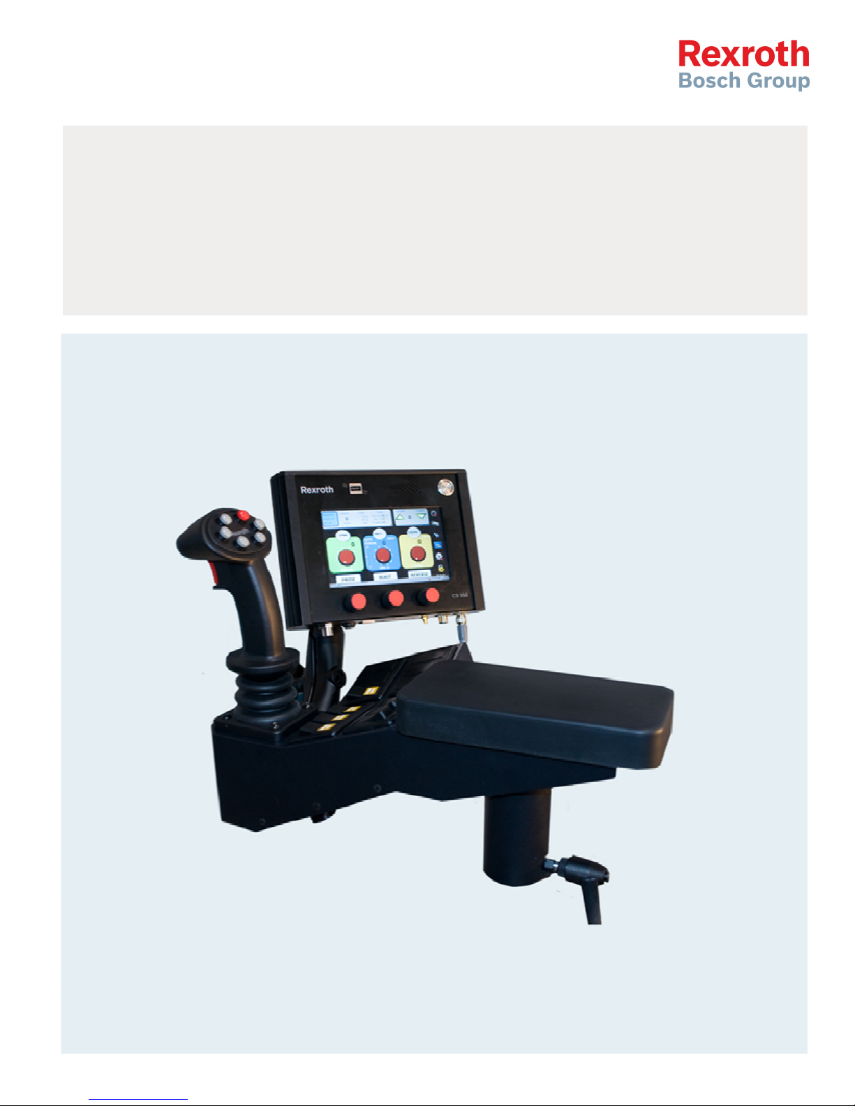
Spreader Joystick Controller Operator Manual
Page 2

2/18
Table o
Table of Content
Table oTable o
1111 Panel Controls
2222 Program
3333 Screen Controls
3.1 Pause 5
3.2 Blast 5
3.3 Reverse 5
3.4 Change Solid Material 6
3.5 Change Prewet Material 6
3.6 Manual Gate Adjustment 6
3.7 Error Messages 7
4444 Symbol Actions
4.1 Error Log/Diagnostic – Gear Symbol 7
4.2 Unloading – UNLOAD Symbol 8
4.3 Data Retrieval/Clear Trip Summary – USB Symbol 9
4.4 Brightness/Volume Adjustment – Backlight Symbol 9
4.5 Manual Hydraulic Gate Adjustment – Cylinder Symbol 10
4.6 Programming Mode – Lock Symbol 10
5555 Joystick Control
5.1 Button Status 11
5.2 Joystick Status 11
5.3 Joystick Screen 11
6666 Anti
7777 Pattern Mode
8888 Air Gate
9999 Liquid+
10
10 Cross Conveyor Mode
1010
11
11 Spinner Reverse
1111
11112222 Error Codes
11113333 Warning
f Contentssss
f Contentf Content
Panel Controls 3333
Panel ControlsPanel Controls
Program Screen Layout
Program Program
Screen Controls 5555
Screen ControlsScreen Controls
Symbol Actions 7
Symbol ActionsSymbol Actions
Joystick Control 11111111
Joystick Control Joystick Control
Anti----ice Mode
AntiAnti
Pattern Mode 11113333
Pattern Mode Pattern Mode
Air Gate Mode
Air GateAir Gate
Liquid+ Mode
Liquid+Liquid+
Cross Conveyor Mode 11114444
Cross Conveyor ModeCross Conveyor Mode
Spinner Reverse Mode
Spinner ReverseSpinner Reverse
Error Codes 11115555
Error CodesError Codes
Warning 11118888
WarningWarning
Screen Layout 4444
Screen LayoutScreen Layout
ice Mode 11112222
ice Modeice Mode
Mode 11113333
ModeMode
Mode 11114444
ModeMode
Mode 11115555
ModeMode
Bosch Rexroth Canada Corp. reserves the right to revise this information at any time and for
any reason and reserves the right to make changes at any time, without notice or obligation,
to any of the information contained in this piece of literature.
Please check for updates at: www.boschrexroth.ca/compu-spread
Bosch Rexroth Canada ı 07.22.2013 ı Revision 2.0
Page 3
3/18
1 Panel Controls
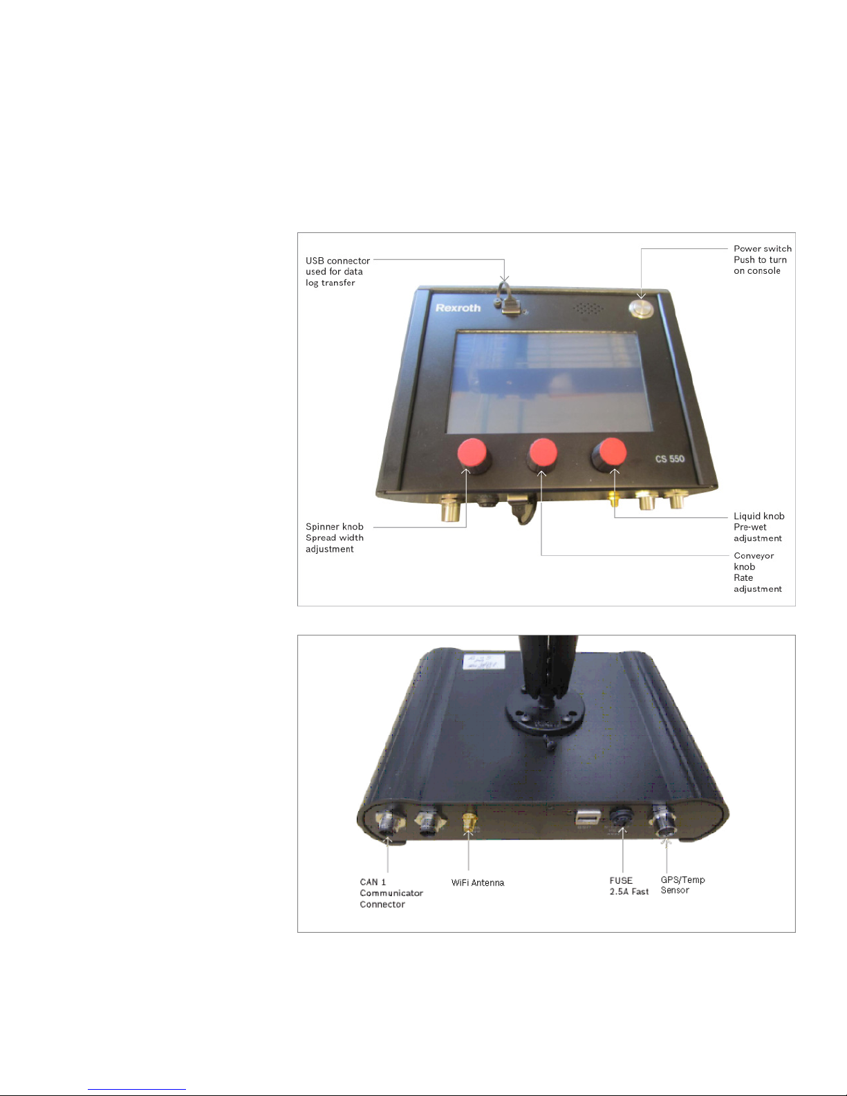
Turn knobs clockwise to increase.
Bosch Rexroth Canada ı 07.22.2013 ı Revision 2.0
Page 4
2 Program Screen Layout
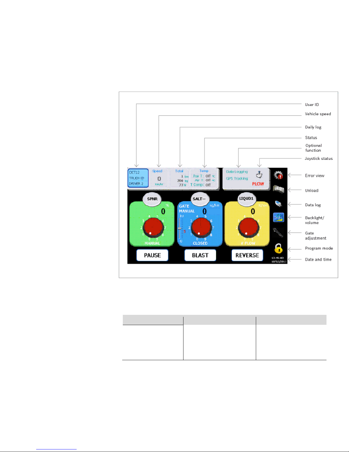
SPNR
SALT
- - LIQUID1
4/18
Spinner Label
Spread Width %
Spinner Setpoint
Spinner Mode
Pause Button
Solid Name
Gate Mode/Solid Rate
Gate Position/Conv Set.
Conveyor Mode
Blast Button
Bosch Rexroth Canada ı 07.22.2013 ı Revision 2.0
Liquid Name
Liquid Rate
Liquid Setpoint
Liquid Mode
Reverse Button
Page 5
5/18
3 Screen Controls
3.1 Pause
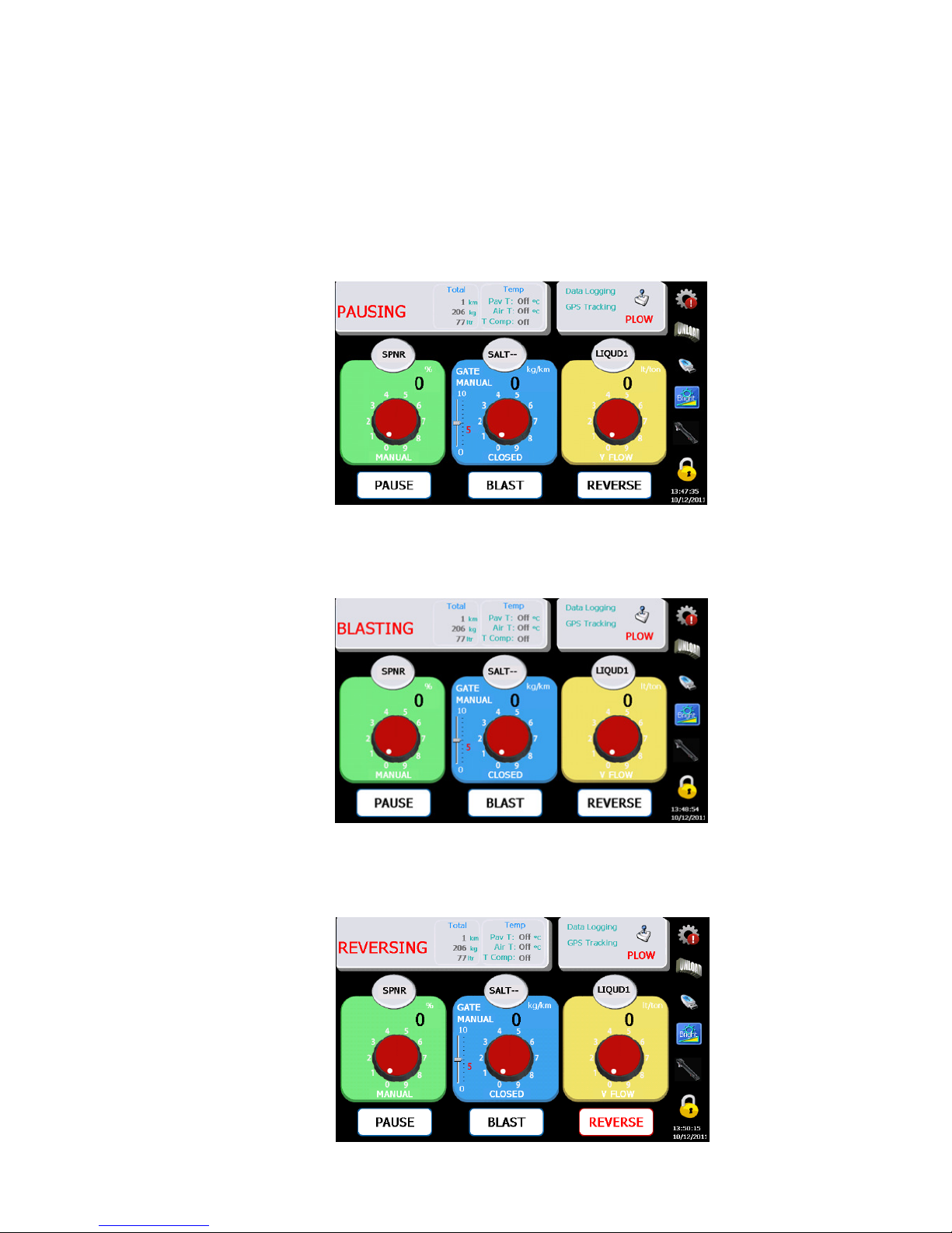
Press the Pause button to pause, and press again to resume spreading.
3.2 Blast
Press the Blast button to increase the spreading output, and press again to resume
regular rate.
3.3 Reverse
Press and hold the Reverse button to change the direction of the Auger (an optional
feature to dislodge obstructions). Release the button to resume spreading.
Bosch Rexroth Canada ı 07.22.2013 ı Revision 2.0
Page 6
6/18
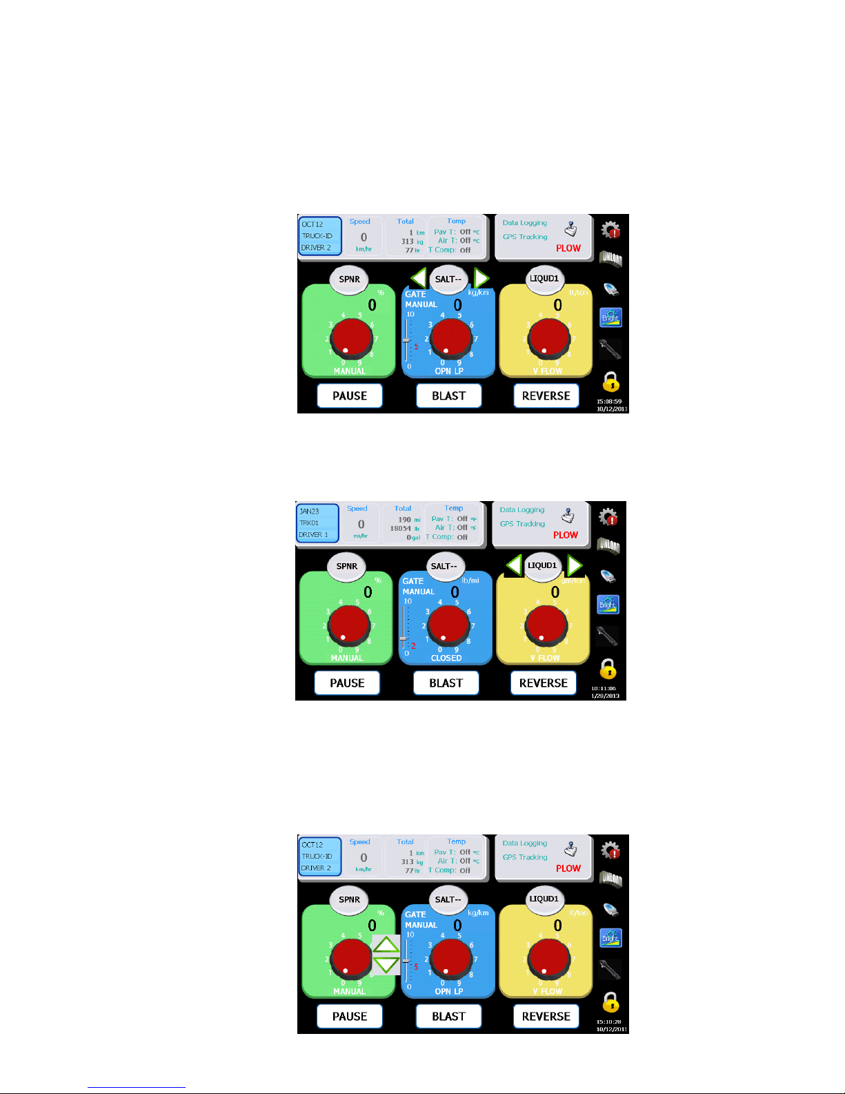
3.4 Change Solid Material
Press the oval button with “SALT- -” text on it to adjust material type. (Note: Vehicle
must be stationary) Use the left and right arrows to change.
Use the Left and Right to
adjust
Press the oval button
again to confirm and save
the selection.
3.5 Change Liquid Material
Press the oval button with the “LIQUID1” text to adjust the material type. (Note:
vehicle must be stationary)
Use the Left and Right
arrows to adjust.
Press the oval button again
to confirm and save the
selection.
3.6 Manual Gate Adjustment
For Manual Gate operation ONLY.
Press the Gate Position Number to select the gate adjustment mode.
Use the up and down
arrows to adjust.
Bosch Rexroth Canada ı 07.22.2013 ı Revision 2.0
Page 7
7/18
Err/Diag
Unload USB
Bright/Vol
Cylinder
Lock
Press the Gate Position again to verify the selection.
3.7 Error Messages
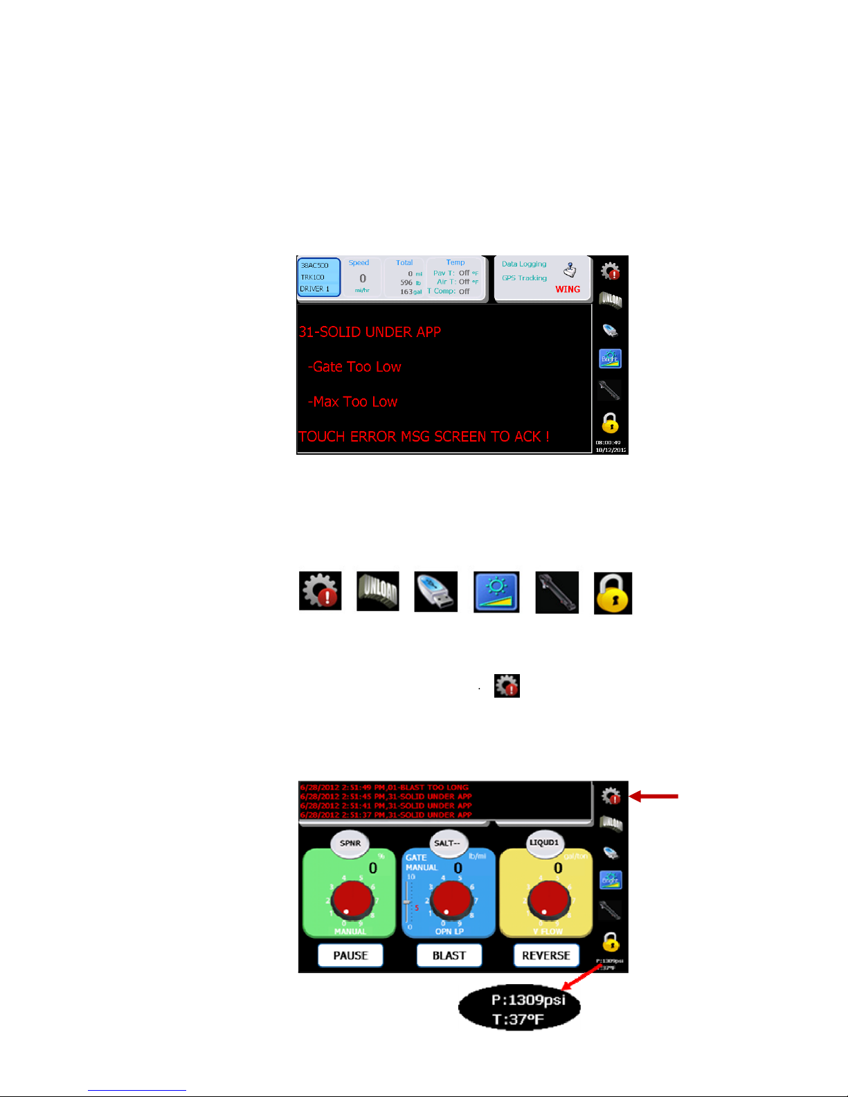
During the operation when an error occurs, a message will appear in the centre of
the screen. Tap anywhere on the message to clear the window.
4 Symbol Actions
All symbols on the right of the screen require a press and hold for >1 seconds.
4444.1
.1 Error
Error Log
Log/Diagnostic
.1 .1
Error Error
When the vehicle is stationary press the ‘Gear
messages. If a hydraulic pressure&temperature sensor is connected both readings
will be displayed on the bottom right of the screen.
/Diagnostic
LogLog
/Diagnostic/Diagnostic
‘Gear’’’’ symbol to display most recent error
‘Gear‘Gear
Bosch Rexroth Canada ı 07.22.2013 ı Revision 2.0
Page 8
A program key is required to clear the error log; hold the button for >5 seconds.
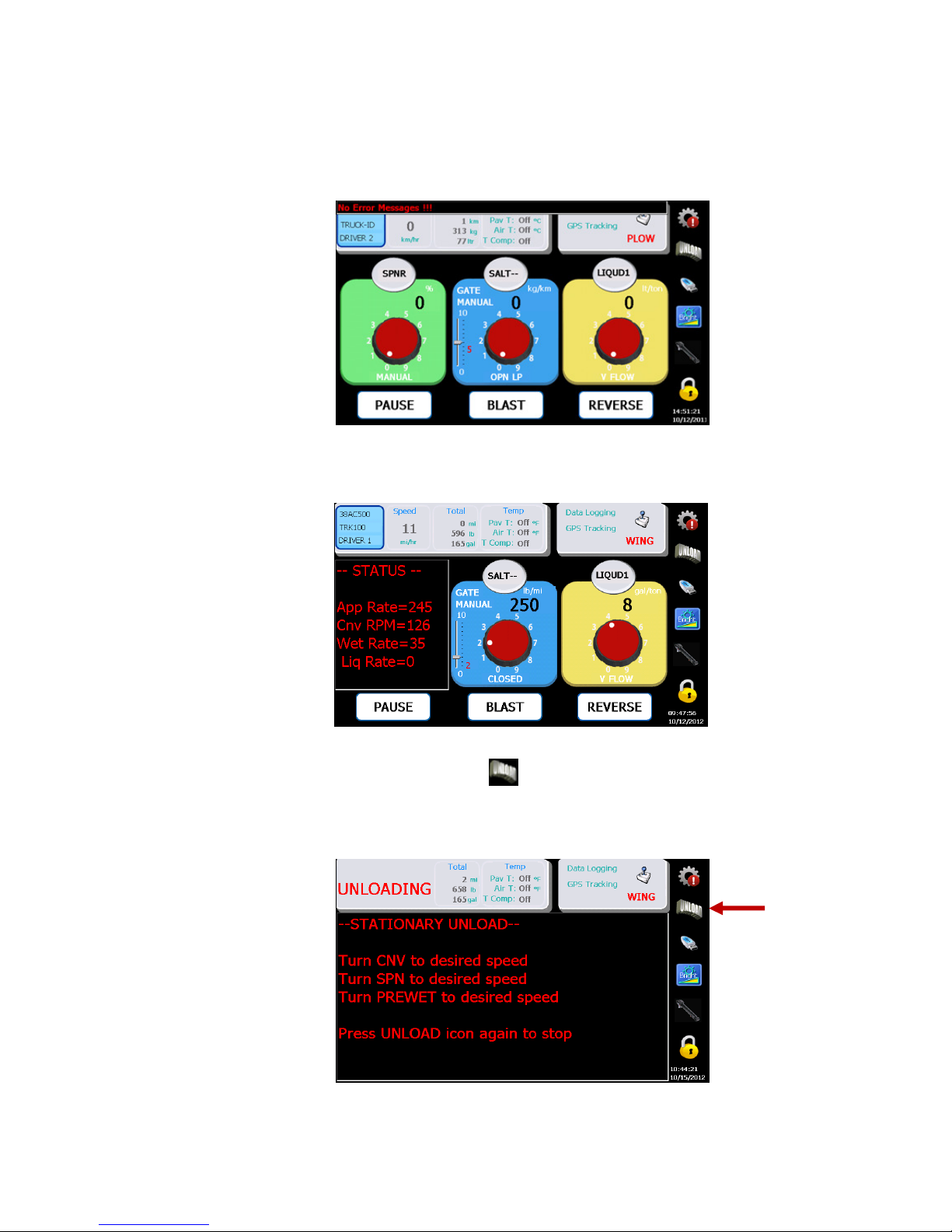
When a vehicle is moving press the ‘Gear’
spreading.
‘Gear’ symbol to display the real-time status of
‘Gear’‘Gear’
4444.2 UNLO
.2 UNLOAD
.2 UNLO.2 UNLO
Press the ‘‘‘‘Unload
stationary.)
ADING
ING
INGING
Turn the dials until the
desired speed is achieved.
Press the symbol again
ADAD
Unload’’’’ symbol to enter into unload mode. (Note: The vehicle must be
UnloadUnload
8/18
Bosch Rexroth Canada ı 07.22.2013 ı Revision 2.0
Page 9
9/18
and to exit unload mode. Moving the vehicle will suspend the unload process. It will
automatically resume when the truck is stopped again.
4444.3
.3
Data
Data Retrieval
.3.3
With a
With a ‘LOG DATA KEY’
With a With a
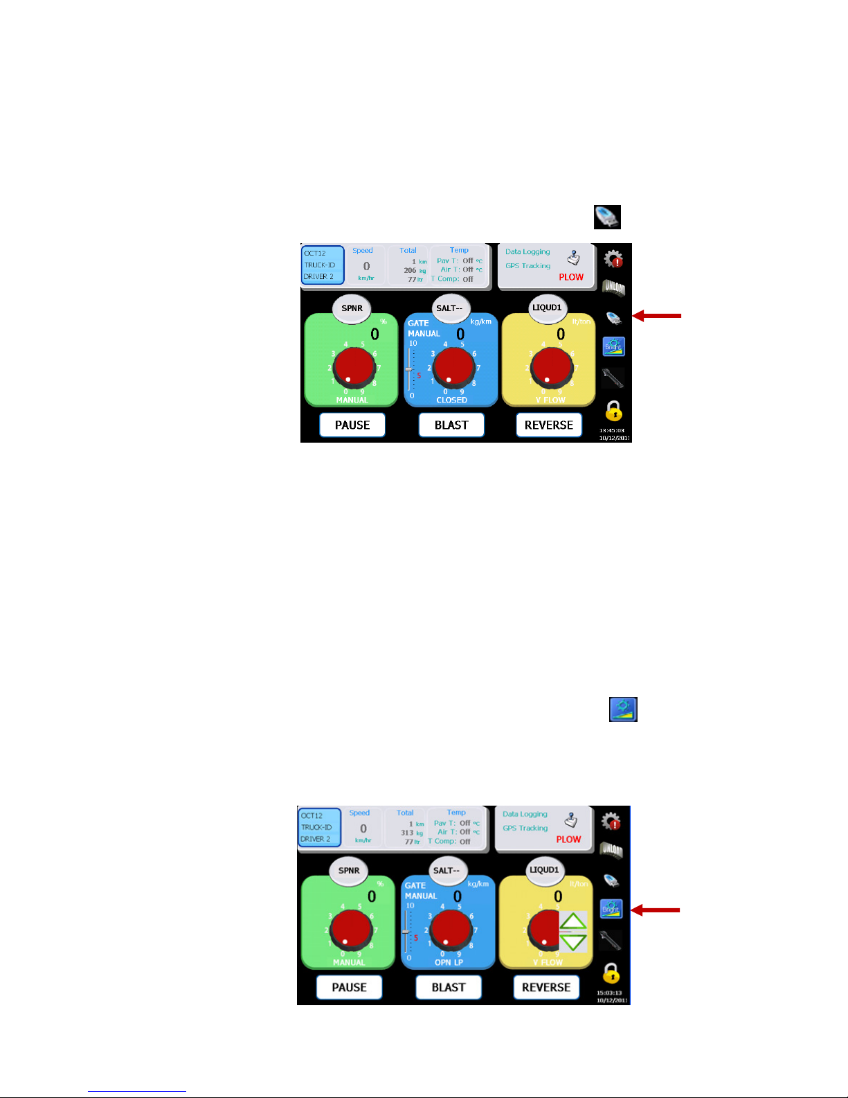
Press the ‘‘‘‘USB
With a
With a ‘PROGRAMMING KEY’
With a With a
Press the ‘‘‘‘USB
Successful” will appear on the screen momentarily when it finishes.
Without a key inserted
Without a key inserted
Without a key insertedWithout a key inserted
Press the ‘USB’
Note: ‘PROGRAMMING KEY’ is for programming and data log. ‘DATA LOG KEY’ is for
log data only.
Retrieval/Clear Trip Summary
Data Data
RetrievalRetrieval
‘LOG DATA KEY’ inserted
‘LOG DATA KEY’‘LOG DATA KEY’
USB’’’’ symbol to transfer the log data.
USBUSB
‘PROGRAMMING KEY’ inserted
‘PROGRAMMING KEY’‘PROGRAMMING KEY’
USB’’’’ symbol to transfer the log data and the parameter. “Transfer
USBUSB
‘USB’ symbol to clear trip summary.
‘USB’‘USB’
/Clear Trip Summary
/Clear Trip Summary /Clear Trip Summary
inserted
inserted inserted
inserted
insertedinserted
4.4 Brightness and Volume Adjustment
Press the ‘‘‘‘Bright/Vol
again to toggle the other mode.
Use the up and down arrows to adjust (only adjustable with vehicle stationary).
Bright/Vol’’’’ symbol to enter into adjustment mode, volume or bright. Press
Bright/VolBright/Vol
Bosch Rexroth Canada ı 07.22.2013 ı Revision 2.0
Page 10
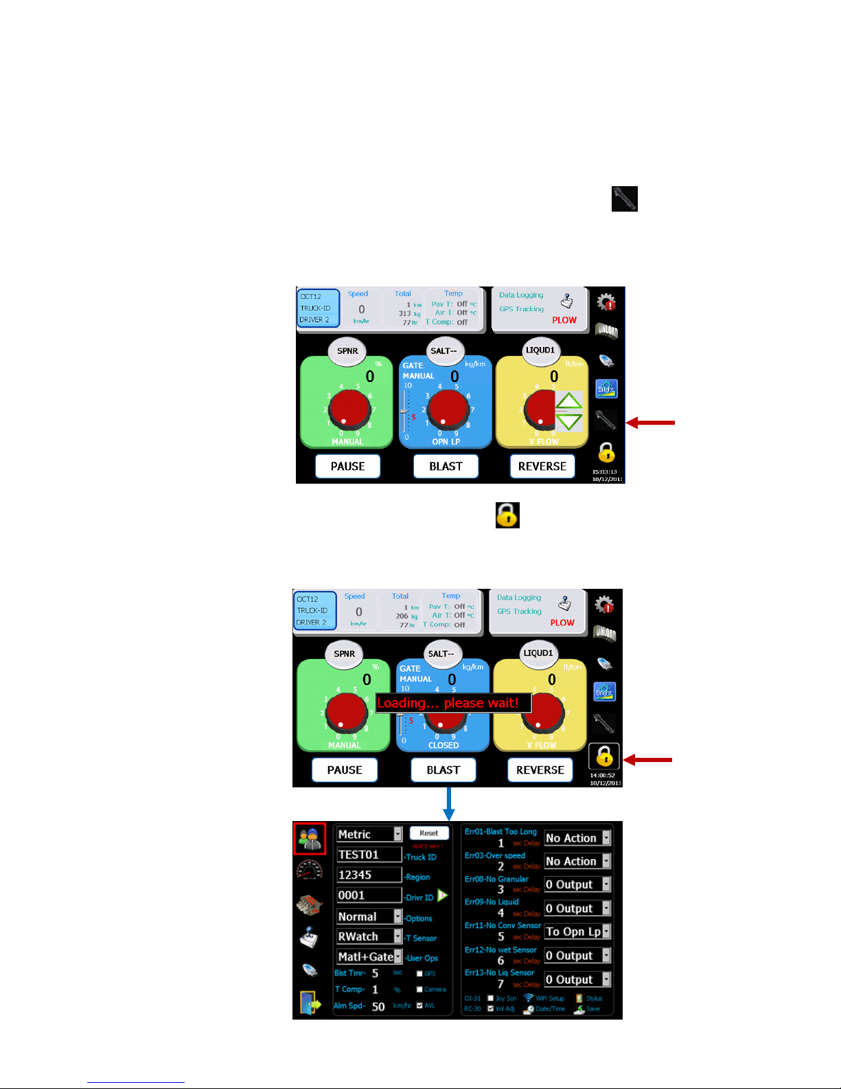
To adjust volume, the “Vol Adj” needs to be checked on setup user screen.
4.5 Manual Hydraulic Gate Adjustment
For hydraulic gate operation ONLY.
Press the ‘‘‘‘Cylinder
down arrows to adjust.
Cylinder’’’’ symbol to select the gate adjustment mode. Use the up and
CylinderCylinder
Press the ‘‘‘‘Cylinder
symbol again to end the
gate adjustment.
Cylinder’’’’
CylinderCylinder
4.6 Programming Mode
Press the ‘Lock’
‘PROGRAMMING KEY’ must be inserted into the USB port.)
‘Lock’ symbol to enter into programming mode. (Note: A valid
‘Lock’‘Lock’
10/18
See Calibration Manual for
programming details.
Bosch Rexroth Canada ı 07.22.2013 ı Revision 2.0
Page 11
11/18
5 Joystick Control
For systems equipped with Joystick Option ONLY.
5.1 Button Status
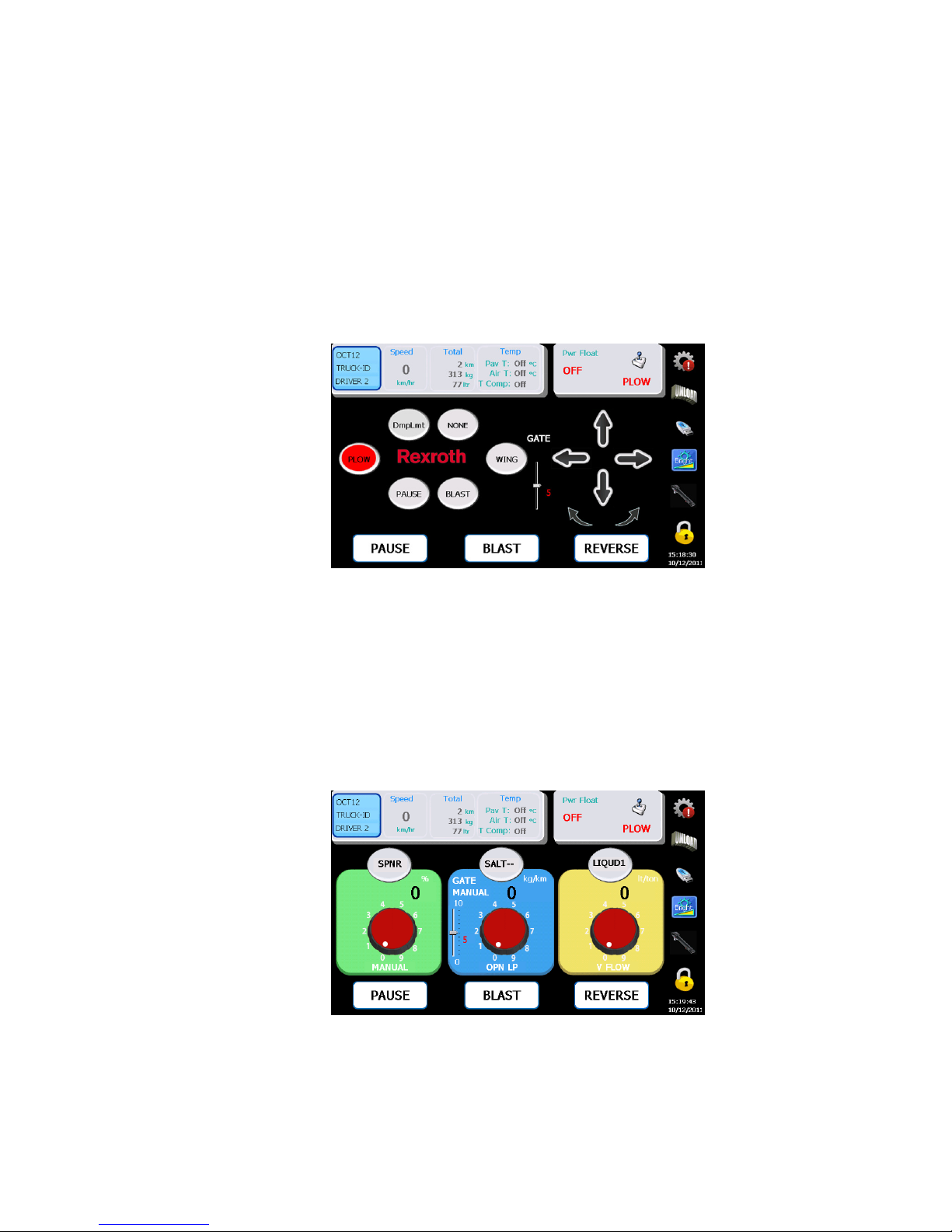
The oval buttons represent the push buttons on the handle of the joystick. When a
joystick button is pushed, the proper mode is illuminated in red.
5.2 Joystick Status
The arrow symbols represent the direction the joystick handle is being deflected.
The mode status is displayed in the top right of both spreader and joystick screens.
5.3 Joystick Screen
Available only when equipped with a CS-150 Armrest Console.
Screen flips when the Deadman Trigger is pressed. When the trigger is released, the
screen reverts back to the spreader layout.
Note: The joystick will only operate while the Deadman Trigger is pulled.
The default spreader or joystick screen is selectable on USER setup screen.
Bosch Rexroth Canada ı 07.22.2013 ı Revision 2.0
Page 12
12/18
6 Anti-ice Mode
6.1 3 Boom
Boom Selection
Boom Selection
Boom SelectionBoom Selection
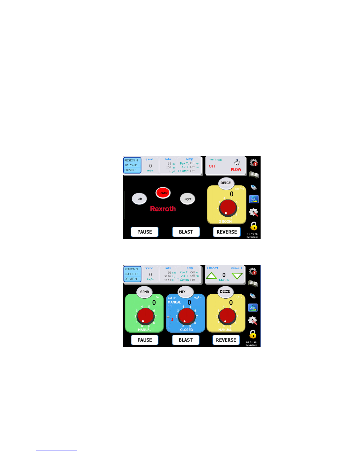
Press the oval buttons to select the desired boom. Pause and Blast operate the
same as a Granular Spreader.
Rate Selection
Rate Selection
Rate SelectionRate Selection
Use the dial on the right to select the desired liquid flow rate. The reverse button is
de-activated.
6.2 Single Boom
Use the upper right arrows to select the desired liquid flow rate.
Bosch Rexroth Canada ı 07.22.2013 ı Revision 2.0
Page 13
7 Pattern Mode
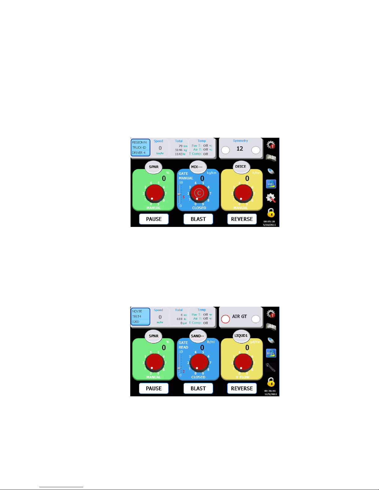
Use the controls on the top right of the screen to control the Chute.
Select left or right with the circular buttons.
Note: To calibrate the centre position you would need to click on the symmetry
reading while a program key is inserted.
13/18
8 Air Gate Mode
Use the controls on the top right of the screen to control the Air Gate.
When vehicle is stationary click on left or right button to toggle between two
materials, and automatically set the operation gate to the calibrated gate for the
material selected.
Bosch Rexroth Canada ı 07.22.2013 ı Revision 2.0
Page 14
14/18
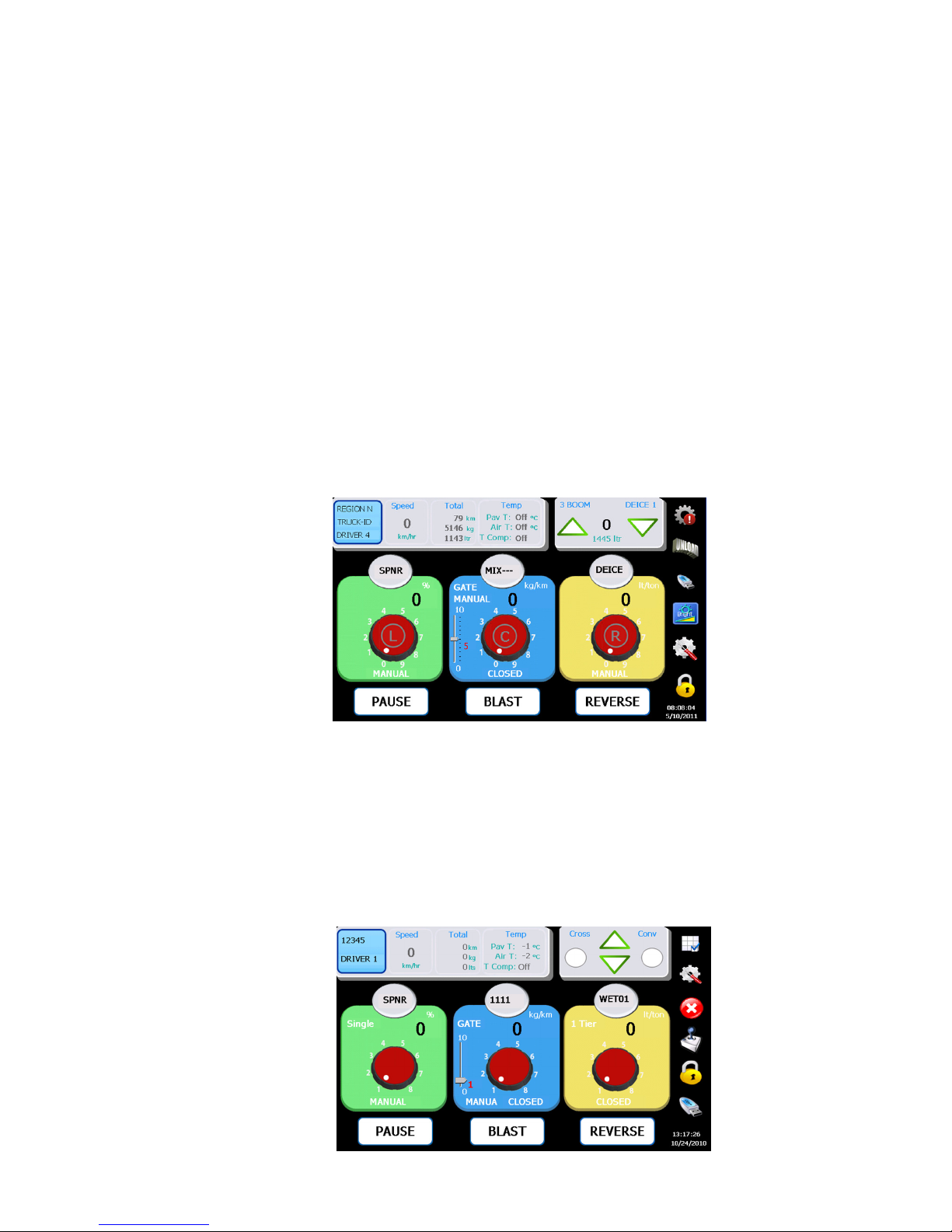
9 Liquid + Mode
This screen is only available when the LIQUID+ mode is selected in the programming
mode. (See Calibration Manual for details.)
Boom Selection
Boom Selection
Boom SelectionBoom Selection
Press the red dial buttons to select the desired Boom. Pause and Blast operate the
same as a Granular Spreader.
Rate Selection
Rate Selection
Rate SelectionRate Selection
Use the upper right arrows to select the desired liquid flow rate.
Solid and Pre
Solid and Pre----wet
Solid and PreSolid and Pre
All standard spreader functions perform as defined earlier in the manual
wet
wetwet
10 Cross Conveyor Mode
Use the controls on the top right of the screen to control the Cross Conveyors.
Select left or right with the circular buttons. Use the up and down arrows to adjust
the speed.
Bosch Rexroth Canada ı 07.22.2013 ı Revision 2.0
Page 15
15/18
E
rror Messages
#
Suggested Solution
11 Spinner Reverse Mode
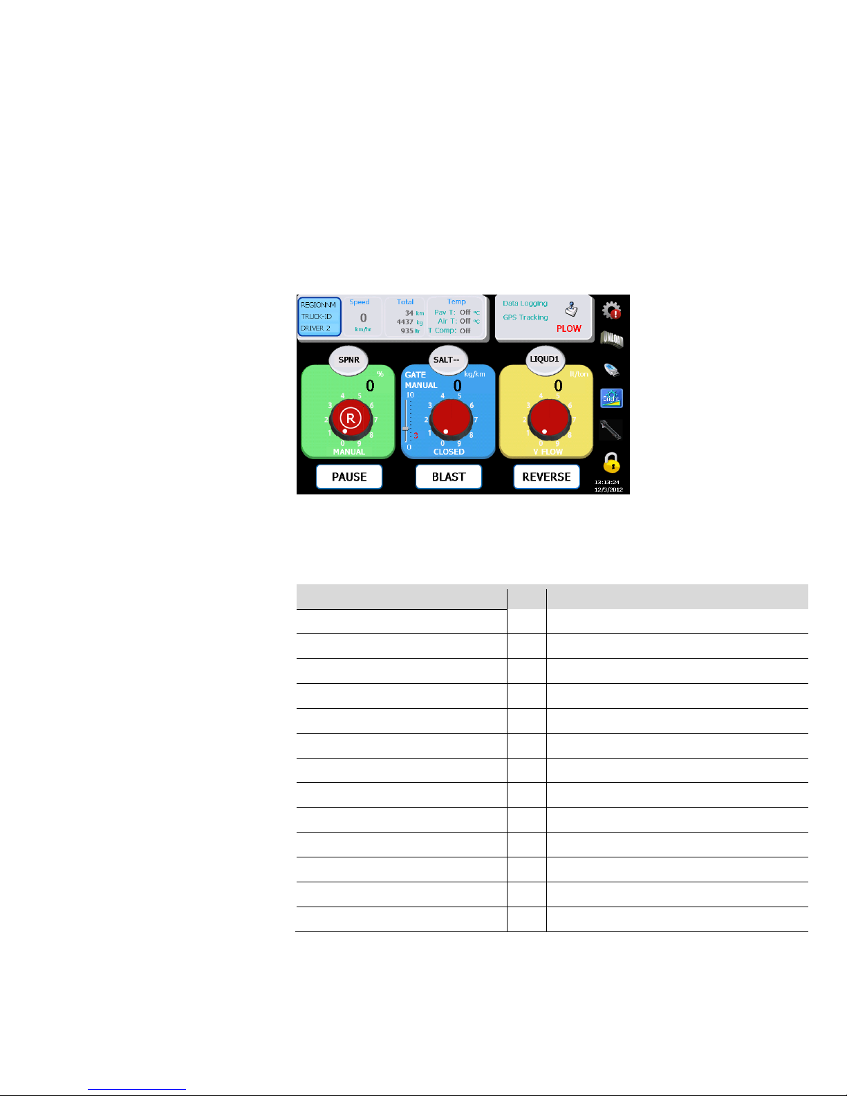
Click the “R” button of spinner knob on the screen to control spinner forward or
reverse.
When the “R” button is pressed the controller would ramp down the spinner from
the speed selected and ramp up to the opposite direction to the speed selected.
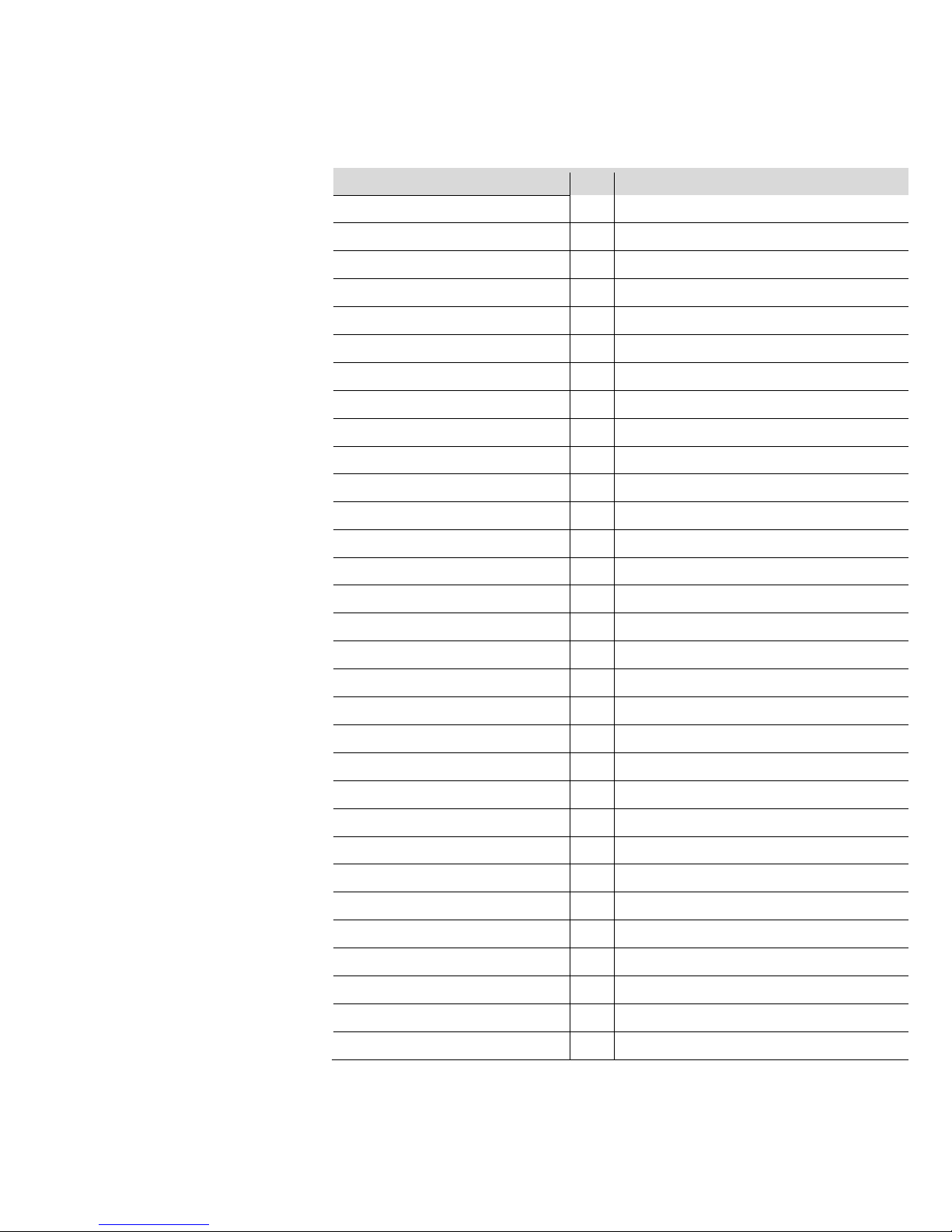
12 Error Codes
ERROR BLAST TOO LONG 1 Turn off blast, reset timer
ERROR DEICE BLST TOO LONG 2 Turn off blast, reset timer
ERROR OVERSPEED 3 Slow down, reset max speed
ERROR SPIN PROP 4 Check cables, replace coil
ERROR CONV PROP 5 Check cables, replace coil
ERROR CROSS1 PROP 6 Check cables, replace coil
ERROR CROSS2 PROP 7 Check cables, replace coil
ERROR NO MATL DETECT 8 Load material, check sensor
ERROR NO LIQ DETECT 9 Load material, check sensor
ERROR NO GROUNDSPEED 10 Check cable/sensor
ERROR NO CONVEYOR 11 Check cable/sensor
ERROR NO LIQUID 12 Check cable/sensor
ERROR NO DEICE 13 Check cable/sensor
Bosch Rexroth Canada ı 07.22.2013 ı Revision 2.0
Page 16
16/18
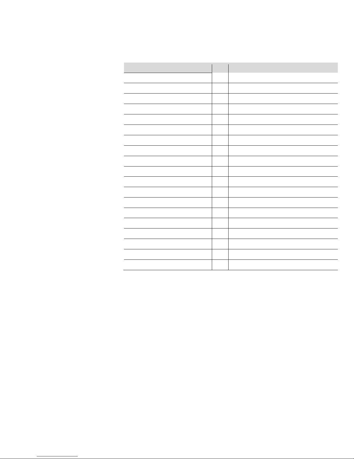
Warning Messages
#
Suggested
Solution
UNLOAD NOT ALLOWED 21 Vehicle needs to be stationary
BB3 SYSTEM ERROR 22 Check if RCE present, Reboot
RC COMMUNICATION ERROR 23 Comm failure between display and RC
RCE COMMUNICATION ERROR 24 Comm failure between RC and RCE
JOY 1 COMMUNICATION ERROR 25 Comm failure between RC and Joystick 1
JOY 2 COMMUNICATION ERROR 26 Comm failure between RC and Joystick 2
NO GATE SENSOR 27 Check gate sensor, cable break
GATE POSITION ZERO 28 Gate closed in READBACK mode
NO GROUND SPEED SIMULATION 29 Speed Simulation mode stopped
UNDER APPLICATION-SPINNER 30 Spinner not able to reach desired RPM
UNDER APPLICATION-CONVEYOR 31 Rate or speed too high, incorrect calibration
UNDER APPLICATION-PREWET 32 Rate or speed too high, incorrect calibration
UNDER APPLICATION-ANTI-ICING 33 Rate or speed too high, incorrect calibration
OVER APPLICATION-COVEYOR 34 Min null or gate too high,
OVER APPLICATION-PREWET 35 Min null too high, rate too low
OVER APPLICATION-ANTI-ICING 36 Min null too high, rate too low
CALIB:GND SPD PULSES TOO LOW 37 Too few or no pulses, recalibrate
SPINNER MAX RPM TOO LOW 38 Bad or no sensor
CONVEYOR MAX RPM TOO LOW 39 Bad or no sensor
PREWET MAX HZ TOO LOW 40 Too few pulses, or sensor failed
ANTI_ICING MAX HZ TOO LOW 41 Too few pulses, or sensor failed
WRONG SPINNER CONTROL MODE 42 Auto null not allowed for MANUAL mode
SPARE 43 Not used
WRONG PREWET CONTROL MODE 44 Auto-null or volume calibration not allowed
WRONG ANTI-ICING CONTROL MODE 45 Check Anti-icing or Cross-Conv modes
WRONG CROSS-CONVEYOR MODE 46 Check Cross-Conv mode setting
WT/REV TOO LOW 47 Check conveyor sensor, and calibrate again
WT/REV TOO HIGH 48 Check conveyor sensor, and calibrate again
PREWET PULSES/GAL TOO LOW 49 Check prewet sensor, and calibrate again
PREWET PULSES/GAL TOO HIGH 50 Check prewet sensor, and calibrate again
ANTI-ICING PULSES/GAL TOO LOW 51 Check anti-icing sensor, and calibrate again
Bosch Rexroth Canada ı 07.22.2013 ı Revision 2.0
Page 17
17/18
Warning Messages
#
Suggested Solution
ANTI-ICING PULSES/GAL TOO HIGH 52 Check anti-icing sensor, and recalibrate
SPNR WIDTH AT 0 RPM TOO LOW 53 Check spinner sensor, and recalibrate
SPNR WIDTH PER RPM TOO LOW 54 Check max width, and recalibrate
GATE MOVEMENT TOO LOW 55 Range too small (Low -> High)
GATE ZERO IN MANUAL 56 Manual Gate set to 0
GATE AT CALIBRATION TOO LOW 57 Calibrated gate needs tob a non-zero value
SPINNER SENSOR PULSES TOO LOW 58 Spinner sensor pulses 0 or too low
CONV SENSOR PULSES TOO LOW 59 Conv sensor pulses 0 or too low
SPINNER OUTPUT RANGE TOO LOW 60 Range between spn Min and Max too small
CONV OUTPUT RANGE TOO LOW 61 Range between Conv Min and Max too small
CROS CONV1 OUTPUT RANGE LOW 62 Range between Cros1 Min and Max too small
CROS CONV2 OUTPUT RANGE LOW 63 Range between Cros1 Min and Max too small
PREWET OUTPUT RANGE LOW 64 Range between prewet Min and Max too small
ANTI-ICING OUTPUT RANGE LOW 65 Range for anti-icing Min to Max too small
JOY1 OUTPUT RANGE TOO LOW 66 Range between Joy1 Min and Max too small
JOY2 OUTPUT RANGE TOO LOW 67 Range between Joy2 Min and Max too small
REQUIRED CONV RPM TOO HIGH 68 Setpoints too high, incorrect wt/rev
REQUIRED PREWET FLOW TOO HIGH 69 Setpoints too high, incorrect pulses/gallon
REQUIRED ANTI-ICING FLOW TOO HI 70 Setpoints too high, incorrect pulses/gallon
Bosch Rexroth Canada ı 07.22.2013 ı Revision 2.0
Page 18

18/18
13 Warning
This glass LCD touch screen display has been extensively tested and validated
against its intended use. This glass could crack and break if the display is dropped
on to a hard surface or receives a substantial impact. If the glass chips or cracks,
discontinue use and contact Bosch Rexroth Canada to have it replaced - do not
touch or attempt to remove the broken glass. Any misuse/abuse causing damage,
whether intended or not, will become the sole responsibility of the owner/buyer
which will render the warranty of this product, void.
Notes:
Bosch Rexroth Canada ı 07.22.2013 ı Revision 2.0
 Loading...