

Bosch CHP CE 400 NE, CHP CE 1200 NE, CHP CE 600 NE, CHP CE 800 NE, CHP CE 1287 NE Technical Manual
...Page 1
Technical guide
System solution
4-draught steam boiler and CHP
with MEC system
6 720 885 509 (2018/03) GB
Page 2

Contents
Systemlösung – 6 720 885 509 (2018/03)
2
Contents
1 System solution: 4-draught steam boiler with
combined heat and power (CHP) . . . . . . . . . . . . 3
1.1 Notice on technical guide . . . . . . . . . . . . . 3
1.2 System solution . . . . . . . . . . . . . . . . . . . . . 3
1.3 Features and benefits . . . . . . . . . . . . . . . . 4
2 System components . . . . . . . . . . . . . . . . . . . . . . 5
2.1 General . . . . . . . . . . . . . . . . . . . . . . . . . . . 5
2.2 Bosch CHP for external waste heat use . . 6
2.2.1 Description CHP CE ... NE . . . . . . . . . . . . . 6
2.2.2 Technical data . . . . . . . . . . . . . . . . . . . . . . 7
2.2.3 Operation conditions CHP . . . . . . . . . . . . 8
2.3 4-draught boiler system . . . . . . . . . . . . . . 9
2.3.1 Description of 4-draught boiler system . . . 9
2.3.2 Technical data . . . . . . . . . . . . . . . . . . . . . 10
2.3.3 Dimensions and connections . . . . . . . . . 11
2.4 MEC System – overview . . . . . . . . . . . . . 13
2.5 Further options for waste heat use/peak
load boiler . . . . . . . . . . . . . . . . . . . . . . . . 14
2.5.1 Waste heat boiler HRSB . . . . . . . . . . . . . 14
2.5.2 3-draught waste heat boiler for use
of waste heat only . . . . . . . . . . . . . . . . . . 15
2.5.3 System extension with peak load boiler . 15
3 Engineering information and sizing . . . . . . . . . 16
3.1 Basic principles . . . . . . . . . . . . . . . . . . . . 16
3.1.1 Economic viability . . . . . . . . . . . . . . . . . . 16
3.1.2 Economic general conditions . . . . . . . . . 16
3.1.3 Technical system data . . . . . . . . . . . . . . . 17
3.2 Pre-dimensioning . . . . . . . . . . . . . . . . . . 18
3.2.1 Estimate design of key components . . . . 18
3.2.2 Investment costs . . . . . . . . . . . . . . . . . . . 18
3.2.3 Evaluation of economic viability . . . . . . . 19
3.2.4 Integration of 4-draught steam boiler . . . 20
3.3 Sizing of key components . . . . . . . . . . . . 23
3.3.1 Sizing of 4-draught steam boiler . . . . . . . 23
3.3.2 Sizing of CHP module . . . . . . . . . . . . . . . 24
3.3.3 Steam amount/waste heat output
and CHP/boiler combinations . . . . . . . . . 24
3.3.4 Demand for useful energy for
make-up water preheating, heating
energy and DHW . . . . . . . . . . . . . . . . . . . 28
3.3.5 Safety equipment . . . . . . . . . . . . . . . . . . 30
3.3.6 System control . . . . . . . . . . . . . . . . . . . . 30
3.3.7 Flue system . . . . . . . . . . . . . . . . . . . . . . . 32
3.4 System design . . . . . . . . . . . . . . . . . . . . . 34
3.4.1 Hydraulics with bypass . . . . . . . . . . . . . 34
3.4.2 Hydraulics without bypass . . . . . . . . . . . 36
3.4.3 Installation . . . . . . . . . . . . . . . . . . . . . . . 38
4 Appendix . . . . . . . . . . . . . . . . . . . . . . . . . . . . . . 40
4.1 List of components . . . . . . . . . . . . . . . . . 40
4.2 Further technical documents . . . . . . . . . . 41
Keyword index . . . . . . . . . . . . . . . . . . . . . . . . . . 42
Page 3

System solution: 4-draught steam boiler with combined heat and power (CHP)
3
Systemlösung – 6 720 885 509 (2018/03)
1 System solution: 4-draught steam boiler with combined heat and power (CHP)
On the background of increasingly scarce natural
resources, sharp increases in energy prices over the last
few years and a turnaround in energy policy, it has
become indispensable, not only from an ecological, but
also from an economic point of view, to review and
reduce one's own energy consumption.
The industrial sector, the most energy-demanding of the
economic sectors, provides a large savings potential.
Often industrial applications require a steam supply
system. Such a system can be optimised concerning
energy consumption and economic viability by using
combined heat and power (CHP) in combination with a
CHP module. In the context of a turnaround in energy
policy, CHP plays a very important role. Its part in the
power generation mix in Germany will increase until
2020 to 25 %.
1.1 Notice on technical guide
The existing technical guide “4-draught boiler and CHP
with MEC system” can be used as information to simplify
the planning and sizing of 4-draught steam boiler system
in combination with combined heat and power unit by
Bosch.
The technical guide shall help you to understand the
basics for using flue gas heat for creating steam in 4draught steam boilers and for designing the components
of a boiler system in conjunction with a combined heat
and power unit (CHP).
The existing technical guide will show possible ways of
execution and respond to open questions concerning
planning, calculation, economic viability and quotation.
1.2 System solution
For commercial and industrial applications, the use of a
CHP system in conjunction with a steam boiler with
integrated waste heat use can be an efficient alternative.
Here, the CHP unit (design as CHP module for external
flue gas use) creates electrical current. A downstream
boiler system uses the hot flue gases of the CHP for
efficient creation of process vapour. The motor heat of
the CHP module can be used for make-up water
preheating, for heating or for DHW heating.
The steam boiler with waste heat utilisation is a
conventionally fired 3-draught steam boiler with
integrated additional fourth draught (4-draught steam
boiler). The hot flue gas of the CHP module is led
through the boiler to support steam production. Thanks
to the integrated combustion in 4-draught steam boilers,
steam peak load boilers are not necessary here that are
usually required with pure waste heat boilers.
Investment costs, space requirements and equipment
effort can be reduced significantly.
The use of a CHP in combination with a 4-draught steam
boiler is gently on the environment in more than one
respect.
The most important aspect is the considerably lower
consumption of primary energy compared to
conventional, separated production of current, steam
and heat. With a CHP, natural resources are saved and
the environment is protected from pollutants from other
combustion processes.
For the combination of a 4-draught steam boiler series
UL-S by Bosch Industriekessel GmbH and a CHP system
by Bosch KWK Systeme GmbH, different system
hydraulics are proposed in this document and their
planning and execution is described (Æ chapter 3.4,
page 34). These are suggestions that allow a simple
realisation.
Page 4

System solution: 4-draught steam boiler with combined heat and power (CHP)
Systemlösung – 6 720 885 509 (2018/03)
4
1.3 Features and benefits
A CHP module provides several benefits, besides saving
resources and reducing the environmental impact,
significant revenues can be achieved using the current
produced by the CHP module.
The revenue is composed of credits for created current
and credits for created heat. Here is must be
differentiated whether the current is produced for own
use of whether it is completely fed in the upstream
mains.
Benefits for end-customers/investors/plant users
• Low consumption of primary energy compared to
conventional, separated production of current, steam
and heat
• Is gentle on the environment: Saves CO
2
and
resources
• Remuneration for self-produced current in
accordance with corresponding national regulations,
e. g. Germany EEG/KWKG
• Amortisation time/ROI of less than 3 years possible
• Sustainable due to decentral energy generation
• Space-saving, no installation of additional peak load
boilers
• Modular system with all benefits of CHP operation
concerning supply reliability, efficiency and current
cost reduction at simultaneously reduced complexity
Benefits for planners/engineers
• Safe planning
– Boiler and CHP module, all from one source
– Functional system hydraulics and standardised
schematic diagrams
– Complete list of components, defined limits of
delivery
– Integration of higher-level control
(Bosch MEC system)
• System safety
– Tuned and certified safety equipment
– All flue gas temperatures from the Bosch CHP
module are securely attained, also in partial load
operation
– Optimised flue gas sound insulation – smoothed
flue gas pulsation, solutions for use in industry,
mixed and residential areas
– Tuned control with bypass dampers with safety
function
– Matched flue system, optimised to admissible flue
gas back pressure of CHP module with regard to
wear of system, maintenance and contamination
– Matched material pairs in flue gas path
• Excellent price/performance ratio/fast ROI/low TCO
– Meaningful, sustainable calculation of economic
viability
– Overall efficiency of CHP module > 70 % by using
waste heat in steam boiler and limiting the flue gas
temperature downstream of the fourth draught/
economiser and use of MEC system
– By using the MEC system, the runtime of the CHP
module is optimised by tuned control strategy.
Page 5
System components
5
Systemlösung – 6 720 885 509 (2018/03)
2 System components
2.1 General
The CHP system with waste heat use for steam
generation consists of 2 key components plus required
accessories.
The key components are:
• A CHP module, designed for flue gas heat utilisation
(without flue gas heat exchanger), consisting of
combustion engine and generator
• A steam boiler with combustion and integrated fourth
draught for waste heat use
• The superordinate control of the combination CHP
and 4-draught steam boiler should be effected by the
Bosch control system MEC system.
The combustion motor is intended for activating the
generator. The hot flue gas, that is created during the
combustion process, with temperatures above 400 °C is
used in the 4-draught steam boiler for steam production.
In addition, during operation of the CHP module, engine
coolant with a temperature of up to 85 °C is created.
Depending on the loss of condensate in the steam
network, this can be used for make-up water preheating
in the steam boiler or for space heating or DHW heating.
The system control “MEC system” controls the
combination of CHP module and 4-draught steam boiler
and optimally integrates is in the compete energy
production system on site.
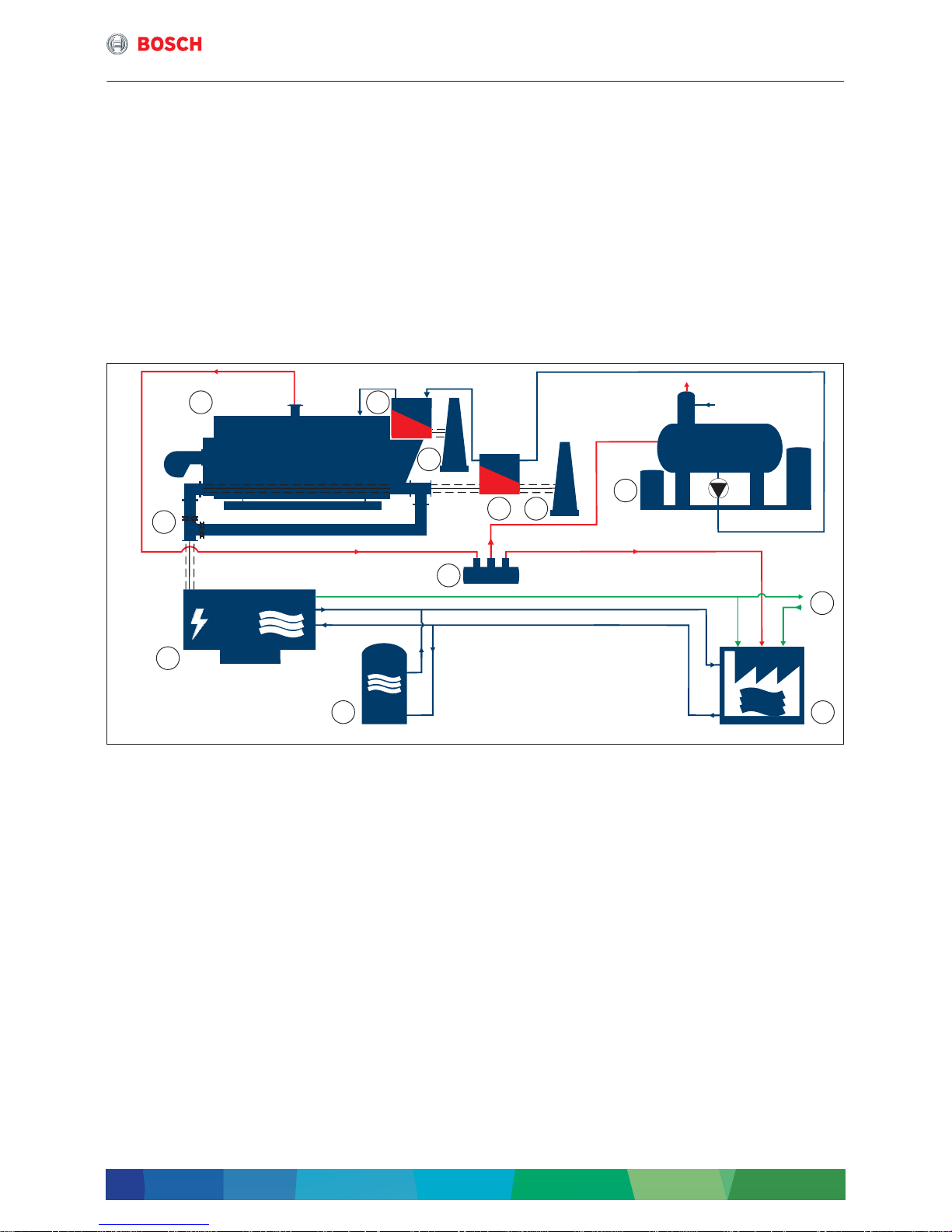
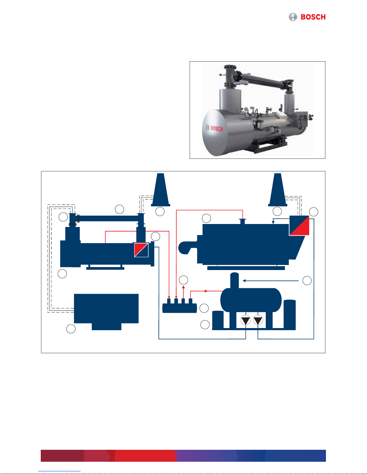
Fig. 1 Simplified function diagram 4-draught steam boiler and CHP module and CHP (simplified depiction)
[1] 4-draught steam boiler
[2] Economiser
[3] Chimney
[4] Flue gas heat exchanger
[5] Water service module
[6] Mains power supply
[7] Consumer
[8] Manifold
[9] Memory
[10] CHP
[11] Flue with bypass
Current
Water/condensate
Steam
Flue gas
If a replacement power supply is necessary, e.g. as in
hospitals or other safety-relevant facilities, a CHP
module can also be used as standby power generator.
6 720 819 535-01.1T
1 2
3
34
5
6
7
8
9
10
11
Page 6
System components
Systemlösung – 6 720 885 509 (2018/03)
6
2.2 Bosch CHP for external waste heat use
2.2.1 Description CHP CE ... NE
The modular construction system of CHP modules for
external waste heat use in the output range
240 kW
el
... 2000 kWel ensures an operation that
simplifies maintenance, commissioning and planning.
Bosch CHP modules care supplied for external waste
heat use in 2 different types and sizes:
• CHP CE ... NE with an output range to 400 kWel.
based on the approved Bosch CHP modules CHP CE
• CHP CE ... NE in the output range 600 ... 2000 kW
el
is a modular CHP module in the output range of
600 ... 2000 kW
el
.
The CHP module consists of a system module, that
can be extended in function via corresponding
accessory modules.
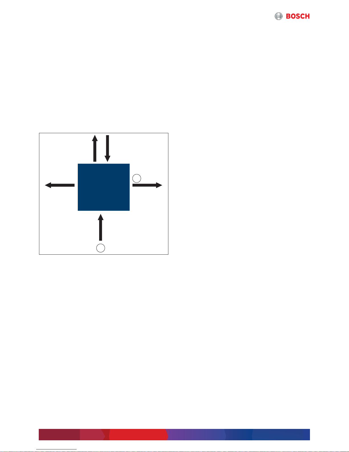
Fig. 2 Decoupling of heat of flue gas and cooling water
in a CHP module, example CHP module with
600 kW
el
performance
[1] Natural gas
[2] Waste heat performance (depending on
temperature change in steam boiler)
Electrical output 240 kW
el
and 400 kW
el
Both CHP modules with electrical output of 240 kWel
and 400 kW
el
are delivered as compact modules, ready
for connection. The components are integrated in the
soundproof cabinet. As ready-for-connection units, the
compact modules are equipped with an integrated
control cabinet. They further comprise a spark-ignited
gas engine (only for CHP CE 400 NE with flue gas
turbocharger) and a synchronous generator for
producing three-phase current (400 V, 50 Hz) and
heating energy. They are suitable for connection,
electrically and for control purposes, to the German lowvoltage network in accordance with VDE-AR-N 4105 or
the regulations of the Federal Association of the German
Energy and Water Industry (Bundesverband der
deutschen Energie- und Wasserwirtschaft, BDEW).
The variant described here spares the internal flue gas
heat exchanger, in consequence the flue gas heat is
available at a high temperature level for external use.
The catalytic converter is installed outside the closed
module frame for easy accessibility.
The flue gas silencers are designed for high
temperatures and a mounted downstream the catalytic
converter and upstream the external heat sink.
Electrical output 600 kW
el
... 2000 kW
el
Modular designed CHP modules are available in the
following output ranges:
• 600 kW
el
• 800 kW
el
• 854 kW
el
• 1200 kW
el
• 1287 kW
el
• 1560 kW
el
• 1718 kW
el
• 1999 kW
el
• 2000 kW
el
The core of the CHP consists of a perfectly tuned unit
with components such as a spark-ignited gas engine
with flue gas turbocharger and a synchronous generator
for producing three-phase current (400 V or 10.5 kV,
50 Hz).
The individual components, such as pumps, heat
exchangers or sensors are combined in modules, wired
and integrated electrotechnically in a terminal box. The
spatial arrangement of the modules can be adapted to
the existing spatial conditions. The options are
constructed in a way that they can be integrated in
existing modules without too much technical effort.
Independently of the ordered options, Bosch CHP
systems provide as standard a comprehensive safety
and fire prevention concept.
The 4-draught CHP modules fulfil, electrically and for
control purposes, the German grid connection
conditions in accordance with
VDE-AR-N 4105 low-voltage or the medium-voltage
regulation by the Federal Association of the German
Energy and Water Industry (Bundesverband der
deutschen Energie- und Wasserwirtschaft, BDEW).
In the variant described here, the CHP module is
designed for external heat utilisation and therefore
provides the flue gas heat for another system. The flue
system is designed for flue gas temperatures up to
550 °C.
Achievable performance of waste heat utilisation in
the steam boiler
The output of the utilised waste heat depends on the
cooling degree of the flue gases in the flue gas boiler. As
an estimate, this is at approx. 20 ... 25 % of natural gas
use in kW.
Bosch BHKW
CHP 600 NE
6 720 819 535-02.1T
1
2 453 °C
75 °C85 °C
333 kW
th
360 kW
th
600 kW
el
1438 kW
~
~
Page 7
System components
7
Systemlösung – 6 720 885 509 (2018/03)
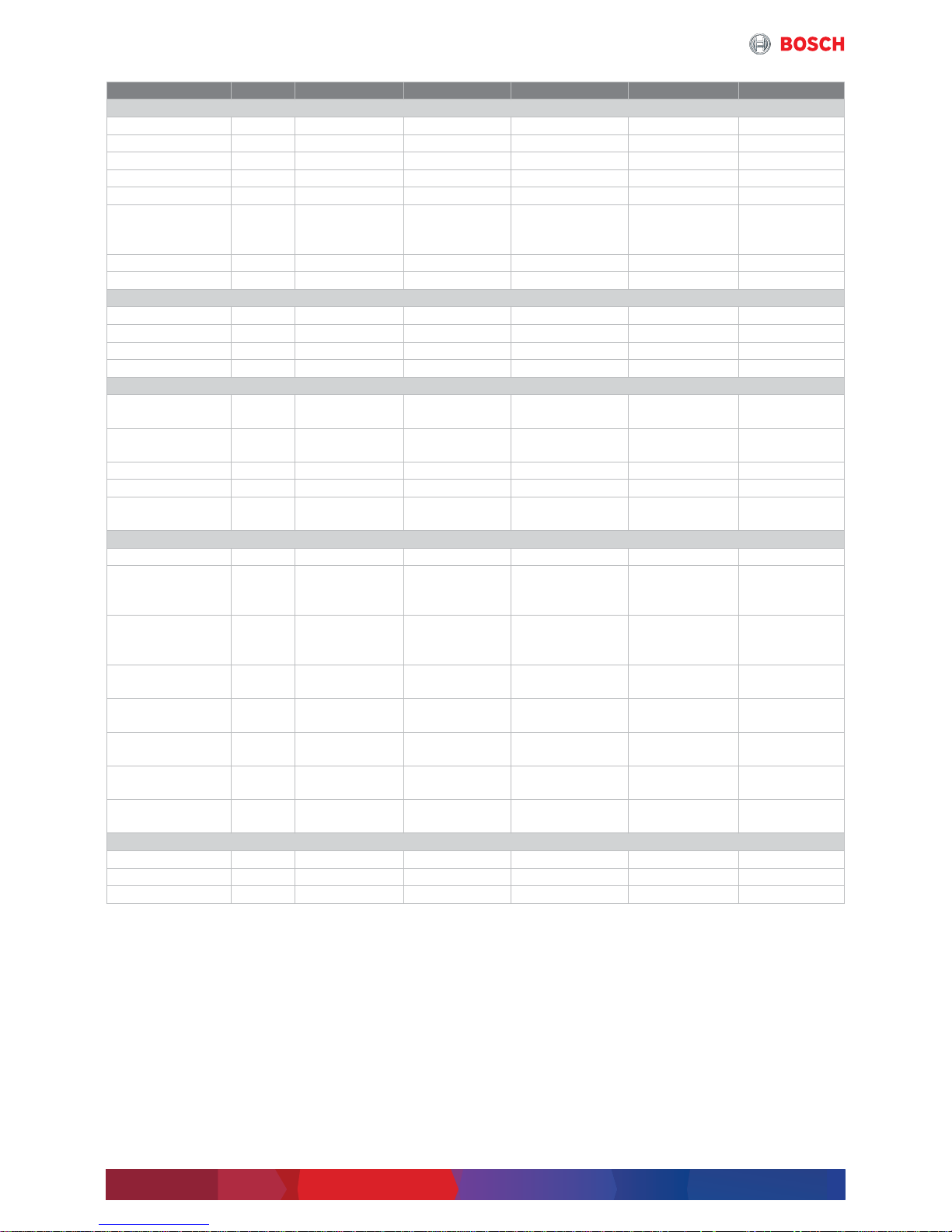
2.2.2 Technical data
Unit CHP CE 240 NECHP CE 400NECHP CE 600 NECHP CE 800
NE
CHP CE 854 NECHP CE 1200
NE
GenSet
Gas category – Natural gas Natural gas Natural gas Natural gas Natural gas Natural gas
Power
consumption
kW 668 1034 1438 1898 1993 2750
Electrical output kW 240 400 600 800 854 1200
Thermal output kW 236 288 333 431 443 625
Electrical
efficiency
% 35.9 38.7 41.7 42.1 42.8 43.6
Type – Design
external flue
gas heat
utilisation
Design
external flue gas
heat utilisation
Design
external flue gas
heat utilisation
Design
external flue gas
heat utilisation
Design
external flue
gas heat
utilisation
Design
external flue
gas heat
utilisation
Engine
manufacturer
– MAN MAN MWM MWM MTU MWM
Engine model – E2842 E 312 E2842 LE 322 TCG 2016 V12 C TCG 2016 V16 C 8V4000 L33 TCG 2020 V12
Dimensions
Length mm 4380 5300 3900 4057 4200 3900
Width mm 1510 1660 2400 1467 2000 2400
Height mm 1980 2472 2260 2190 2300 2260
Weight (empty) kg 4400 6950 6670 7550 10000 11730
Generation of electricity
Generator
manufacturer
– Leroy Somer Leroy Somer Marelli Marelli Stamford Marelli
Generator type – LSA 47.2
M7/4P
LSA 47.2 M7/4P
LSA 49.1 S4/4P
MJB 400 LC4 MJB 450 MB4 PE734C MJB 500 MB4
Voltage/Frequency V/Hz 400/50 400/50 400/50 400/50 400/50 400/50
Speed 1/min 1500 1500 1500 1500 1500 1500
Efficiency of
generator
% 96.1 96.2 96.8 97.1 95.9 97.3
Temperature levels
LT mixture circuit °C – 47.5/45 44/40 46/40 42/40 43/40
Heating water
without flue gas
heat exchanger
°C 83/70 82/72 85/75 85/75 85/75 85/75
Flue gas
temperature
without flue gas
heat exchanger
°C 570 440 453 452 443 414
Maximum flue gas
temperature
°C 650 650 550 550 550 550
Flue gas tube
dimension (KAT)
– DN 200/PN 10 DN 200/PN 10 DN 250/PN 10 DN 300/PN 10 DN 300/PN 10 DN 350/PN 10
Flue gas mass flow
rate (wet)
kg/h 877 2102 3343 4418 4524 6551
Available flue gas
back pressure
mbar 15 17 25 25 25 25
Flue gas back
pressure boiler
mbar 10 10 15 15 15 15
Flue gas limit values
CO mg/m
3
i.N.
d300 d300 d300 d300 d300 d300
NOx mg/m
3
i.N.
d250 d500 d250 d250 d250 d250
NMHC mg/m
3
i.N.
d150 d150 d150 d150 d150 d150
Table 1 Specifications CHP CE 240 NE ... CHP CE 1200 NE
Page 8
System components
Systemlösung – 6 720 885 509 (2018/03)
8
2.2.3 Operation conditions CHP
The following operating conditions are required to
maintain the warranty:
• Ensure dust and halogen-free cooling and
combustion air
• Ensure that the exhaust air and exhaust gas lines are
correctly dimensioned, and run them separately
• Maximum setup height without a drop in
performance: depending on model used 100 ... 500
meters above zero
• Ratio of starting/operating hours: 1 start to 6
operating hours averaged over the year
• Methane count: 80
• Natural gas Hi = 10 kWh/m
3
• Maximum exhaust gas counterpressure depending on
GenSet motor manufacturer 40 ... 60 mbar
• Module only suitable for setup within a building
• The condensate and flue gas line are pressurized and
must be appropriately designed, and the operating
pressure must be demonstrated in a pressure test.
Unit CHP CE 1287 NE CHP CE 1560 NE CHP CE 1718 NE CHP CE 1999 NE CHP CE 2000 NE
GenSet
Gas category – Natural gas Natural gas Natural gas Natural gas Natural gas
Power consumption kW 2974 3629 3991 4666 4588
Electrical output kW 1287 1560 1718 1999 2000
Thermal output kW 664 819 974 1076 1053
Electrical efficiency % 43.3 43 43 42.8 43.6
Type – Design
external flue gas
heat utilisation
Design
external flue gas
heat utilisation
Design
external flue gas
heat utilisation
Design
external flue gas
heat utilisation
Design
external flue gas
heat utilisation
Engine manufacturer – MTU MWM MTU MTU MWM
Engine model – 12V4000 L33 TCG 2020 V16 16V4000 L33 20V4000 L33 TCG 2020 V20
Dimensions
Length mm 4800 6300 5500 5900 7820
Width mm 2000 1800 2000 2000 1800
Height mm 2300 2500 2300 2400 2680
Weight (empty) kg 12000 13400 15000 19000 18100
Generation of electricity
Generator
manufacturer
– Stamford Marelli Leroy-Somer Stamford Marelli
Generator type – PE734F MJB 500 LA4 LSA 51.2
VL95 C6S/4P
LV804T MJB 560 LB4
Voltage/Frequency V/Hz 400/50 400/50 400/50 400/50 400/50
Speed 1/min 1500 1500 1500 1500 1500
Efficiency
generator
% 96.5 97.1 96.5 96.3 97.4
Temperature levels
LT mixture circuit °C 43/40 44/40 43/40 43/40 45/38
Heating water
without flue gas heat
exchanger
°C 85/75 85/75 85/75 85/75 85/75
Flue gas temperature
without flue gas heat
exchanger
°C 440 426 426 449 410
Maximum flue gas
temperature
°C 550 550 550 550 550
Flue gas tube
dimension (KAT)
– DN 350/PN 10 DN 400/PN 10 DN 400/PN 10 DN 450/PN 10 DN 450/PN 10
Flue gas mass flow
rate (wet)
kg/h 6700 8665 8940 10458 10983
Available flue gas
back pressure
mbar 25 25 25 25 25
Flue gas back
pressure boiler
mbar 15 15 15 15 15
Flue gas limit values
CO mg/m
3
i.N.
d300 d300 d300 d300 d300
NOx mg/m
3
i.N.
d250 d250 d250 d250 d250
NMHC mg/m
3
i.N.
d150 d150 d150 d150 d150
Table 2 Specifications CHP CE 1287 NE ... CHP CE 2000 NE
Page 9
System components
9
Systemlösung – 6 720 885 509 (2018/03)
2.3 4-draught boiler system
2.3.1 Description of 4-draught boiler system
The basis of a 4-draught steam boiler is a 3-draught
boiler from which a part of the smoke tubes is
separated. The hot flue gases of the CHP module
(in the design for external flue gas utilisation) are lead
through this separate smoke tube field, the so-called
fourth draught, and are used for steam generation.
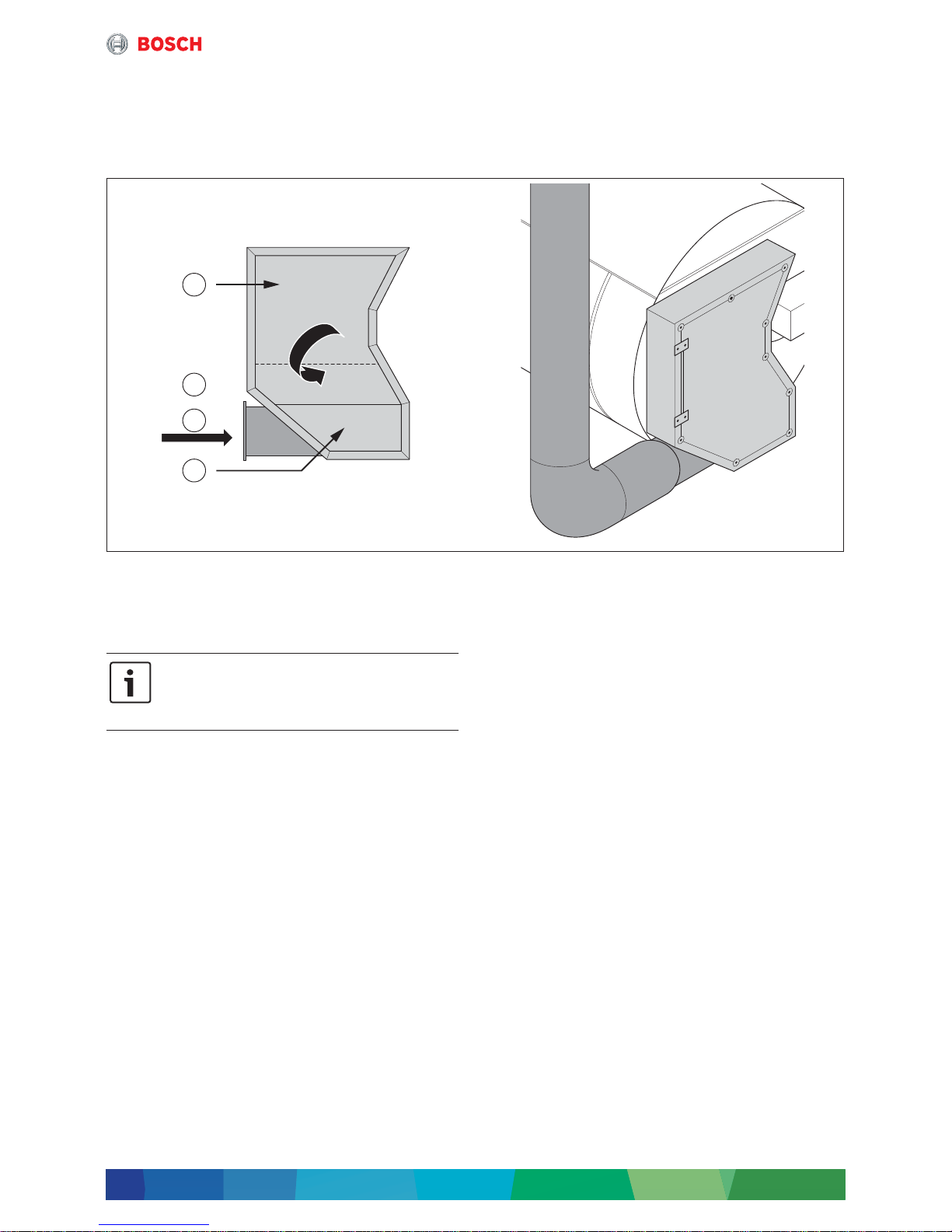
Fig. 3 Positioning of fourth draught in reversing chamber
[1] Second draught
[2] Third draught
[3] Flue gas
[4] Fourth draught
Due to different pressure ratios on burner and waste
heat side, and for avoiding back coupling, both flue gas
paths have to be clearly separated on the flue gas side.
This separation concerns, besides the boiler and
possibly existing economisers, also the flue gas routing
via 2 separate chimneys.
The auxiliary units required for a 4-draught steam boiler,
such as e.g. water treatment, feed water degassing
system, fuel supply, pumps etc. will not be treated
further in this document, because their requirements
concerning sizing and installation do not differ from a
conventional boiler system.
Especially, it has to be observed that the installation
location of the feed water control valve is between the
two economisers, in order to increase economic viability
and to save steam for heating up the feed water. In
addition, it is recommended to equip the feed water
container with an overflow device.
This ensures that an unwanted activation of the pressure
relief valve at the feed water container is prevented
during waste heat recovery of the CHP module in the flue
gas heat exchanger (ECO2) with at the same time very
low to no steam generation. Both points are shown in
the hydraulics (Æ chapter 3.4, page 34).
6 720 819 535-03.1T
1
2
3
4
By dividing the third draught, the amount of
steam generated by waste heat is limited for
the total output of the boiler
(Æ chapter 3.3.3, page 24).
Page 10
System components
Systemlösung – 6 720 885 509 (2018/03)
10
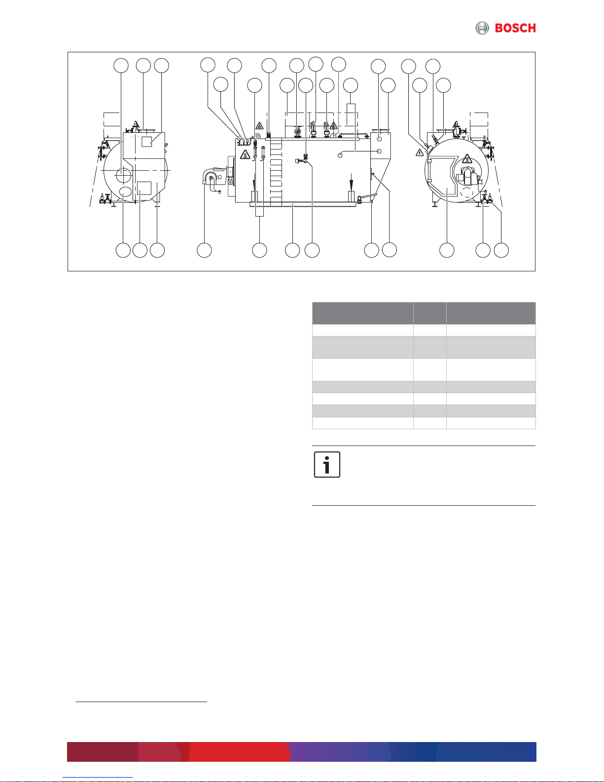
Fig. 4 Overview UNIVERSAL steam boiler
[1] Inspection aperture on the flue gas side
[2] Flue gas connecting branch
[3] Inspection aperture on the flue gas side
[4] Pressure indicator (with test function)
[5] Pressure transducer
[6] Pressure limiter
[7] Shut-off valve
[8] Vent shut-off valve (optional)
[9] Maintenance platform (optional)
[10] Steam shut-off valve
[11] Desalination shut-off valve
1)
[12] Positive pressure safety valve 2 (optional)
[13] Positive pressure safety valve 1
[14] Lifting lug
[15] Connection pipework
[16] Connection economiser
[17] Flue gas heat exchanger
[18] Conductivity transducer
[19] Terminal box
[20] Level measurement transformer
[21] Level limiter
[22] Mud quick action stop valve
[23] Outlet shut-off valve
[24] Reversing chamber door
[25] Flame inspection hole
[26] Connection for flue gas condensate
drainage system
[27] Desalination control valve
[28] Base frame
[29] Level indicator 1
Level indicator 2 (optional)
[30] Burner
[31] Flue gas chamber
[32] Inspection aperture on the flue gas side
[33] Inspection aperture water-side
2.3.2 Technical data
6 720 819 535-04.1T
1 2 3 8710
912111413 17
222324
25
26272830313233 29
19
16 182120
15
6
5
4
1) For boiler type UL-S 28000 there are 2 desalination
connections.
Unit UNIVERSAL
steam boiler
Type – UL-S
Heat transfer medium – High pressure
saturated steam
Type – 4-draught flue tube
technology
Performance kg/h 1250 ... 28000
Safety pressure bar d30
Maximum temperature °C 235
Fuel – Oil, gas
Table 3 Specifications UNIVERSAL steam boiler
The 4 ... 5-digit number in the boiler name
corresponds to the respective steam output
in kg/h.
1 kg/h corresponds to 0.65 kW burner
output.
Page 11
System components
11
Systemlösung – 6 720 885 509 (2018/03)
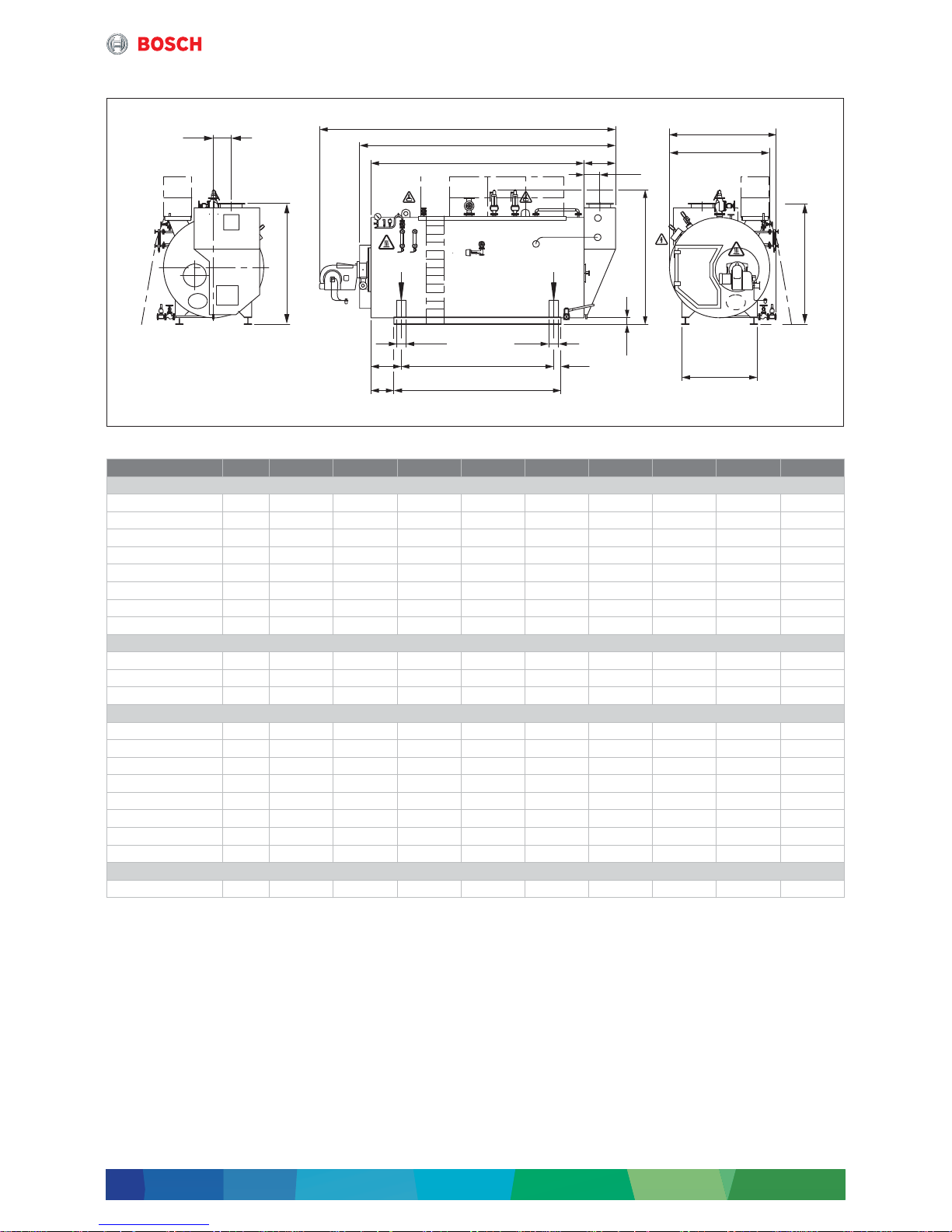
2.3.3 Dimensions and connections
Fig. 5 Dimensions and connections UNIVERSAL steam boiler UL-S
Unit UL-S 1250 UL-S 2000 UL-S 2600 UL-S 3200 UL-S 4000 UL-S 5000 UL-S 6000 UL-S 7000 UL-S 8000
Dimensions
L1
1)
1) The dimension L1 is a recommended dimension and is subject to the burner manufacturer, type and the actual steam output.
mm 4850 4653 4972 5927 6615 6615 7255 7255 7845
L2
2)3)
2) Minimum transport dimensions when valves, burner and terminal box have been removed
(without cable conduit; with cable conduit + 75 mm on the right).
3) Dimension increases depending on dimension of flue of CHP.
mm 3280 3820 4260 4760 5450 5450 6210 6210 6800
L3 mm 2620 2970 3270 3770 4600 4600 5100 5100 5550
L6 mm 500 640 780 780 640 640 780 780 920
B1 mm 1929 2102 2187 2182 2439 2634 2674 2774 2874
B2
2)
mm 1652 1825 1910 1905 2165 2360 2400 2500 2600
H1
4)
4) The dimension H1 varies depending on the valve manufacturer.
mm 2262 2512 2557 2642 2947 3177 3222 3312 3562
H2
2)5)6)
5) Dimension depending on selected flue gas temperature (influenced by number of tubes in height of economiser).
6) For boiler type UL-S 28000 there are 2 desalination connections.
mm 2150 2232 2210 2210 2575 2765 2975 2958 3178
Flue gas connection
L11 mm 233 303 373 373 303 303 373 373 443
B4 mm 170 270 290 290 318 273 119 153 85
H3
5)
mm 2150 2232 2210 2210 2575 2765 2975 2958 3178
Base frame
L4 mm 2270 2570 2120 2625 3750 3500 4000 4000 4450
L5 mm 1890 2150 1770 2175 3400 3150 3650 3650 3950
L7 mm 385 425 750 798 600 775 675 675 800
L8 mm 175 215 575 573 425 600 500 500 550
L9 mm 170 210 175 225 175 175 175 175 250
L10 mm 80 80 150 150 225 225 225 225 275
B3 mm 1060 1100 1360 1360 1655 1785 1820 1890 1950
H4 mm 200 190 135 135 190 165 160 150 170
Wide-flange beam
IPB/HEB – DIN1025 mm – – – – 180 180 180 180 200
Table 4 Dimensions and connections UNIVERSAL steam boiler UL-S 1250 ... UL-S 8000
6 720 819 535-05.1T
L1
L2
L3
L10 L10
L7 L5 L9
L8
L4
L6
L11
B4
H3
H2
H1
H4
B3
B1
B2
Page 12

System components
Systemlösung – 6 720 885 509 (2018/03)
12
• For information and instructions regarding the
requirements for the boiler installation room
Æ Technical information TI024
(Æ chapter 4.2, page 41)
• Equipment and complete dimensions according to
project-specific technical datasheet
• Measure the maximum weight at the front and back
feet of the foundation.
• Dimensions given with r1 % tolerance
• These dimensions are designed for standard
insulation
– 150 mm thick on floors
– 100 mm thick on casing
• The boiler types UL-S 1250/2000/2600/3200 have
inspection apertures on the right side, instead of the
bottom.
• For boiler types UL-S 1250 ... UL-S 3200, the outlet
shut-off valve and the mud quick action stop valve are
mounted in the boiler axis to the back to ensure
accessibility of the inspection aperture on the
water side.
• The boiler type UL-S 4000 has additional inspection
apertures on the side at the bottom.
• Sizing for the entrance
– Transport height: additional clearance of at least
100 mm from dimension H1 or dimension H2
(valves fitted/not fitted)
– Minimum door clearance: additional clearance of at
least 200 mm from dimension B1 or dimension B2
(valves fitted/not fitted)
• The height of the boiler room is determined by the
system equipment. The clearance above the
maintenance platform should be at least 2 m.
• For boiler types UL-S 1250 ... UL-S 3200 optionally a
shaft extension is available for the steam shut-off
valve.
• Level measurement transformer and level limiter
(image 4, [20] and [21], page 10) are positioned for
boiler type UL-S 1250 and UL-S 2000 on the top of the
boiler.
Unit UL-S
10000
UL-S
12000
UL-S
13000
UL-S
14000
UL-S
16000
UL-S
17000
UL-S
18000
UL-S
22000
UL-S
28000
Dimensions
L1
1)
1) The dimension L1 is a recommended dimension and is subject to the burner manufacturer, type and the actual steam output.
mm 8369 9007 9008 8674 9854 9920 9944 9610 9868
L2
2)3)
2) Minimum transport dimensions when valves, burner and terminal box have been removed
(without cable conduit; with cable conduit + 75 mm on the right).
3) Dimension increases depending on dimension of flue of CHP.
mm 6860 7265 7446 7456 8286 8286 8286 8705 8955
L3 mm 5550 5800 5800 5800 6630 6630 6630 7050 7050
L6 mm 980 1135 1136 1146 1146 1146 1146 1145 1395
B1 mm 3074 3224 3474 3474 3474 3669 3674 3874 4199
B2
2)
mm 2800 2950 3200 3200 3200 3400 3400 3600 4000
H1
4)
4) The dimension H1 varies depending on the valve manufacturer.
mm 3732 3867 4222 4222 4222 4467 4467 4747 5212
H2
2)5)6)
5) Dimension depending on selected flue gas temperature (influenced by number of tubes in height of economiser).
6) For boiler type UL-S 28000 there are 2 desalination connections.
mm 3065 3200 3465 3465 3465 3710 3685 3835 4302
Flue gas connection
L11 mm 503 588 588 598 598 598 598 598 778
B4 mm 240 240 380 380 380 380 380 635 600
H3
5)
mm 2923 2990 3270 3270 3270 3415 3415 3420 3585
Base frame
L4 mm 4450 4450 4700 4700 5500 5500 5500 5800 5800
L5 mm 3950 3950 4200 4200 5000 5000 5000 5200 5200
L7 mm 800 800 775 800 800 800 800 925 925
L8 mm 550 550 525 550 550 550 550 625 625
L9 mm 250 250 250 250 250 250 250 300 300
L10 mm 275 275 275 275 275 325 325 325 325
B3 mm 2080 2180 2340 2340 2340 2365 2365 2500 2700
H4 mm 140 125 140 140 140 185 185 160 225
Wide-flange beam
IPB/HEB – DIN1025 mm 200 200 240 240 240 260 260 260 300
Table 5 Dimensions and connections UNIVERSAL steam boiler UL-S 10000 ... UL-S 28000
Page 13

System components
13
Systemlösung – 6 720 885 509 (2018/03)
2.4 MEC System – overview
Transparent, efficient, smart
The MEC System (Master Energy Control) is a platform
for planning individual and customer-specific energy
supply systems. With the MEC system, you can combine
and control different plant types and field devices to
achieve an efficient energy system via user interface. The
MEC system is used in commercial, industrial and
communal sectors and is sold as system solution with
Bosch heat sources.
Activation
The MEC system controls different plant types
(e. g. boilers, CHPs) and the required system field
devices (e. g. pumps, valves). For this purpose, it
provides a large range of interfaces and, besides
integration of Bosch devices, it allows for integration
of existing and third-party products.
System control
The system control is the core know-how of the MEC
systems. As manufacturer of energy generation plants,
Bosch used its entire expert knowledge for developing
control and allows in consequence for optimum system
control with adherence to the system's operating
conditions.
Control for energy generation
The MEC system integrates for energy generation as
standard the following plant types:
• Warm water boiler
• Hot water boiler
• Steam boiler
• Biomass boiler
• CHP modules
• Solar
• Heat pumps
• Buffer storage tanks
• External heat
Further systems and plants are available on request.
Control for heat distribution
The range of functions for control of heat distribution
comprises:
• Local heat network
• Heating circuits
• Fans
• Heating circuits
• DHW heating
Further functions and control of systems and devices are
available on request.
System access
The MEC system gives humans and machines access to
the entire system:
• Via an integrated local web server, the user can
access the system using any terminal device
(such as PC, notebook or tablet) in the network with
a standard web browser.
• With the modern and intuitive user interface, the user
can access the complete system and each individual
plant.
• Having a large number of interfaces, the MEC system
allows for integration in super-ordinate systems, such
as building control systems, process control systems,
energy management and virtual power plant systems.
• Using MEC remote, the user has the opportunity to
access the local system from the Internet via a safe
connection.
Web and IP technologies
Web and IP technology have the following benefits:
• HMI scalable to different screen sizes
• Mouse and touch screen operation
• Unlimited number of terminal devices for visualisation
• Location-independent for terminal devices and
controller
• Simple network building with standard components
for large factory sites
• Easy integration in corporate networks
Comprehensive HMI functionality
The modern and intuitive HMI of the MEC system has
many benefits:
• Coloured, clear visualisation of states, temperatures
and performance
• Visualisation of device, system and operation
• User management
• Alarm management with alarm history
• Appliance configuration via HMI system
• Search
• Dashboard function
• Energy monitoring
• Diagram displays
• Export and print-out of graphs
• Transmission of alarms via e-mail, text message, fax
• Run time prognosis of CHP module
New HMI standards
The MEC system uses new standards for visualisation:
• The concept of operation is tuned to the end
customer's requirements
• Intuitive and new operation
• Structured and clear design
• Modern design
Page 14
System components
Systemlösung – 6 720 885 509 (2018/03)
14
2.5 Further options for waste heat use/peak load boiler
As an option, for waste heat use only of a CHP, further
Bosch industrial boilers can be used.
2.5.1 Waste heat boiler HRSB
As alternative to a 4-draught industrial steam boiler, a
pure waste heat boiler can be used. This variant should
be preferred in case of retrofitting (existing boiler
system). A bypass already exists in the waste heat boiler.
Fig. 6 Bosch waste heat boiler HRSB
Fig. 7 Simplified function diagram Bosch waste heat boiler HRSB and CHP (simplified depiction)
[1] Flue CHP module
[2] Flue bypass
[3] Chimney
[4] Economiser
[5] Peak load steam boiler
[6] Make-up water
[7] Water service module WSM-V
[8] Manifold
[9] Consumer
[10] CHP
[11] Waste heat boiler
Water/condensate
Steam
Flue gas
6 720 819 535-11.1T
6 720 819 535-12.1T
1
2
3
3
4
4
6
7
8
9
10
11
5
Page 15

System components
15
Systemlösung – 6 720 885 509 (2018/03)
2.5.2 3-draught waste heat boiler for use of waste heat only
If, due to very high waste heat mass flow or very high flue
gas temperatures, the limits of use of the waste heat
boiler HRSB should not be sufficient, a
3-draught waste heat boiler can be used for waste heat
utilisation only.
Fig. 8 Bosch 3-draught waste heat boiler
2.5.3 System extension with peak load boiler
If the motor waste heat provided by the CHP module is
not sufficient for the heating water supply or if it shall be
supply also redundantly to the CHP module, the system
can be extended by a boiler for covering these loads.
Fig. 9 Function diagram: System extension via peak load boiler (strongly simplified depiction)
[1] 4-draught steam boiler
[2] Economiser
[3] Chimney
[4] Flue gas heat exchanger
[5] Water service module
[6] Mains power supply
[7] Consumer
[8] Boiler
[9] Manifold
[10] Memory
[11] CHP
[12] Flue gas bypass
Current
Water/condensate
Steam
Flue gas
6 720 819 535-13.1T
6 720 819 535-14.1T
1
2
3
3
5
6
7
8
10
9
11
12
4
Page 16

Engineering information and sizing
Systemlösung – 6 720 885 509 (2018/03)
16
3 Engineering information and sizing
3.1 Basic principles
3.1.1 Economic viability
The economic viability of a system combined of CHP
with waste heat use in a 4-draught steam boiler is an
important criterion for making decisions on investment
and should therefore be made already during the basic
evaluation of the project.
In the following, important general conditions are shown
for the use of the described system combinations. These
general conditions are preconditions for an economic
use and allow for a first evaluation of economic
efficiency.
On this basis, the system can be dimensioned.
3.1.2 Economic general conditions
Creation of steam
Basic condition is a demand as continuous as possible of
water vapour for effecting thermal processes with a
required temperature level clearly above 100 °C. In
general, this is industrial process vapour.
When using the vapour, it has to be differentiated
between direct and indirect heating.
For indirect heating, the steam dispenses its
evaporation enthalpy (energy that is set free in the boiler
during water evaporation) via a heat exchanger to the
medium to be heated. The thus produces condensate is
led back to the steam boiler.
For direct heating, steam is directly lead to the medium
to be heated, the medium absorbs the steam in general
and no condensate forms, or the condensate cannot be
supplied to the process without additional measures.
A complete or partial direct heating requires an
increased additional amount of water. Energy required
for preheating can be supplied by motor waste heat of
the CHP module and can lead to an increased runtime of
the CHP module.
Internal power consumption
A CHP module creates high-temperature heat, lowtemperature heat and current.
The current of the CHP system can be used for internal
power consumption or can be supplied to the public
power network.
The infeed of current to the public network can be
promoted depending on CHP size in acc. with KWKG
(CHP Act, Germany).
For the economic viability of a CHP module, it is crucial
to clearly define the currently valid subsidy conditions.
If the created power is used internally, the economic
efficiency of the CHP module increases with the price
difference between electricity tariff and gas price.
LT heat (low-temperature heat)
In order to efficiently operate a CHP module, a high
amount of annual operating hours is required. Main task
is here the use of motor waste heat (temperature level
of approx. 85/70 °C).
The motor waste heat can be used for process heat,
for DHW heating, for heating or for make-up water
preheating for steam production. Here a heat transfer as
continuous as possible is important.
HT heat (high temperature heat)
For a CHP module with external waste heat use, the
motor flue is used for steam production at temperatures
above 110 °C in an external steam generator
(Æ chapter 2).
Summary
The used fuels and resulting energy flow should be
known.
Only if you know the energy consumption and energy
costs, you can optimally plan a system.
For designing and operation of an economically efficient
system, a use as continuous as possible of lowtemperature heat, steam and also internal current is
crucial.
The larger the margin between the energy price for gas
and the energy price for current, the higher the
efficiency of a CHP system.
At ... hours of
operation per year
a cost-efficient use of a CHP
module is ...
2000 very unlikely
3000 unlikely
4000 possible
5000 likely
6000 very likely
Table 6 Economic viability of a CHP module in relation to
the number of hours of operation in a year
For system reasons, current, LT heat and HT
heat are always created simultaneously. To
ensure a high annual efficiency, during CHP
operation a performance assessments by
the corresponding generators in the steam
boiler should be effected.
Page 17

Engineering information and sizing
17
Systemlösung – 6 720 885 509 (2018/03)
3.1.3 Technical system data
In the following, the maximum and minimum system
parameters are summarised in an clearly arranged table.
Using the table, you will get a quick overview whether
from a technical point of view a 4-draught steam boiler
or a CHP module should be used.
Medium System parameters Unit Within system limits
Yes No
Steam Performance Min. 1250 kg/h
Max. 28000 kg/h
4-draught
steam boiler
Part of fourth
draught
(waste heat)
Max. 20 %
Positive pressure Max. 30 bar
Steam
temperature
Max. 235 °C
Current Performance Min. 240 kW
el.
Max. 2000 kW
el.
Voltage Min. 230 V
Max. 400 V
Heating
water
Performance Min. 230 kW
th.
CHP Max. 1100 kW
th.
Pressure rating Max. 6 bar
Temperature Flow 83 ... 85 °C
Return d70 °C
Waste heat Performance Min. 120 kW
th.
Max. 1300 kW
th.
Waste heat
temperature
Ø 450 °C
Max. 650 °C
Table 7 Technical system data
Page 18

Engineering information and sizing
Systemlösung – 6 720 885 509 (2018/03)
18
3.2 Pre-dimensioning
During a first planning phase, an estimate design of the
important system parts, a cost estimate and a
preliminary consideration of economic efficiency are
crucial.Important functional principles have to be
explained with schematic diagrams.
3.2.1 Estimate design of key components
Estimate sizing of 4-draught steam boiler
The size of the steam boiler can approximately be
calculated from the total of the individual steam
consumers plus an addition of approx. 10 % as own
steam consumption. If consumption times of individual
consumers are already defined, coincidence factors can
possibly be taken into consideration.
Estimate sizing of CHP module
The waste heat performance in the steam boiler from the
CHP module must not exceed maximum 20 %.
Estimate of elapsed time
To achieve an informative profitability assessment, the
theoretic runtimes of steam boiler and CHP module have
to be determined, by means of the existing load profiles
or operating specifications for sufficiently precisely
defined load profiles.
3.2.2 Investment costs
As a sound basis for an investment decision and for
evaluation of the investment costs and preliminary
consideration of economic efficiency, the system with
4-draught steam boiler and CHP module with MEC has to
be compared with the construction of a 3-draught boiler
system.
The shown cost estimate is based on the following
framework conditions:
• Output steam boiler, 2000 kg/h each
• Output BHKW 400 kW
el.
• Peak load boiler for heating and DHW production
700 kW
th.
• The costs have been determined incl. installation and
incidental expenses. The height of this share of costs
strongly depends on the particular local conditions of
the project. The following cost estimate is therefore
exemplary.
Position Size Unit Investment costs 4-
draught steam boiler and
CHP with MEC system
Investment costs steam
boiler
[€] [€]
Steam boiler 2000 kg/h – 110 000
Steam boiler, 4-draught steam design 2000 kg/h 130 000 –
CHP module 400 kW
el.
350 000 –
Waste heat line incl. silencer – – 15 000 –
Flue gas line/chimney – – 30 000 20 000
MSR technology – – 35 000 25 000
Floor standing condensing boiler, peak
load for heating
700 kW
th.
20 000 20 000
Installation costs – – 120 000 100 000
Required building measures – – 50 000 40 000
Other services – – 50 000 50 000
Planning costs 10 % 100 000 45 000
Safety margin/contingencies 5 % 50 000 25 000
Total –– 950 000 435 000
Table 8 Investment costs
Page 19

Engineering information and sizing
19
Systemlösung – 6 720 885 509 (2018/03)
3.2.3 Evaluation of economic viability
In the following assessment of economic viability, the
calculation is based on a runtime of approx. 5,300 h/a
for steam boiler and CHP module. The calculation is
carried out conservatively, e. g. statically, with regard to
the basic year and without consideration of energy price
increase. The costs are individually calculated for fuel,
current, cost allocation and refunds as well as for
occurring service costs. The additional investment costs
and the savings during operation result in an
amortisation time (ROI) for investment.
Energy costs
Running costs
Summary
The increased investment costs in this example pay off within 3 years.
Position Rate Unit Annual
consumpti
on
Unit Annual consumption
costs 4-draught steam
boiler and CHP with
MEC system
Annual
consumption costs
steam boiler
[€] [€]
Fuel demand steam boiler 35 €/MWh 5800 MWh – 203 000
Fuel demand steam boiler, 4-
draught steam design
35 €/MWh 5000 MWh 175 000 –
Fuel demand CHP module 35 €/MWh 5300 MWh 186 900
Fuel demand floor standing
condensing boiler
35 €/MWh 2700 MWh – 94 500
700 MWh 25 700 –
Power drawn 150 €/MWh 1600 MWh 246 900 –
3500 MWh – 525 000
Cost allocation, internal power
consumption
– – – – 45 300 –
Reduction peak load 90 €/kW 400 kW – 36 000 –
Reimbursement of petroleum tax – – – – – 29 400 –
Total of consumption costs 614 000 822 500
Table 9 Energy costs
Position Annual service costs 4-draught steam
boiler and CHP with MEC system
Annual service costs
steam boiler
[€] [€]
Service costs floor standing
condensing boiler
500 500
Annual service costs steam boiler 4500 4500
Service costs CHP module 35 000 –
Total of running costs 40 000 5 000
Table 10 Running costs
Costs €/a Annual running costs 4-draught steam
boiler and CHP with MEC system
Unit Annual running costs
steam boiler
Unit
Investment 950 000 € 435 000 €
Additional investment costs 515 000 € – –
Consumption 614 000 € 822 500 €
Appliance operation 40 000 € 5000 €
Total of consumption costs 654 400 €/a 827 500 €/a
Additional consumption
costs
– 173 100 €/a
ROI 3.0
Table 11 Summary
Page 20

Engineering information and sizing
Systemlösung – 6 720 885 509 (2018/03)
20
3.2.4 Integration of 4-draught steam boiler
The integration of a 4-draught steam boiler is effected
via the flue of the CHP module. Here, 2 versions have to
be distinguished.
4-draught steam boiler with bypass
By installing a bypass, an operation independently of the
CHP module is possible. Instead of shutting down the
CHP module in case of a boiler fault or after achieving
the boiler target pressure, the bypass mode is activated,
thus current and LT heat continue to be produced.
Also during maintenance on the steam boiler, the CHP
module can be operated in bypass mode, but is has to
be observed that all inspection apertures on the flue gas
side are closed during operation of the CHP module to
prevent reverse flow of fuel.
Fig. 10 4-draught steam boiler with bypass
Changing from normal to bypass operation is effected
via pneumatically controlled flaps in the flue gas line of
the CHP module. Here one of the bypass flaps is opened
and subsequently the flue gas line leading to the fourth
draught of the boiler is closed. The flue flows unused
directly to the chimney, and passes the boiler and
possibly existing economisers. It has to be observed that
always one flue gas path is open and that both flue gas
paths are never closed at the same time. The flap control
is monitored with regard to safety, so that at eventual
faults, the system is securely shut down.
The bypass operation should only be used
for a limited time.
Otherwise all heat contained in the flue is
lost, because no flue gas heat exchanger is
connected to the bypass. In consequence,
the efficiency of the total plant is
considerably reduced.
6 720 819 535-06.1T
Page 21

Engineering information and sizing
21
Systemlösung – 6 720 885 509 (2018/03)
4-draught steam boiler without bypass
If a system is installed without bypass, the entire flue gas
mass flow rate of the CHP module is led via the fourth
draught of the steam boiler. In consequence, when the
boiler target pressure is achieved, not only the boiler but
also the CHP module have to be shut down, to prevent
further increase of the boiler pressure. Due to this fact,
at times of low steam consumption, pulsing of the CHP
module can occur.
Fig. 11 4-draught steam boiler without bypass
6 720 819 535-07.1T
Page 22

Engineering information and sizing
Systemlösung – 6 720 885 509 (2018/03)
22
Additional Economiser (ECO)
Due to the precise separation on the steam gas side
between burner side and waste heat side, a further
increase in efficiency can be obtained with the 4-draught
steam boiler by implementing a second economiser. On
the burner side, usually an integrated economiser is
used. The Economiser for the CHP module however is
installed as “Stand-Alone” version behind the fourth
draught of the boiler.
The connection of the economisers is effected in parallel
on the flue gas side and in rows on the water side,
whereby ECO of the fourth draught in flow direction is
always passed through first. Due to the feed water
control valve with pump freewheel function between
both economisers, part of the feed water can be led
back to the feed water container and the container can
be used as heat reservoir. In consequence, runtimes of
the CHP module as well as the efficiency of the system
can be increased. For this, the feed water container
must be equipped with an overflow device.
At factory, the economisers are designed to the currently
valid temperature limits and are protected from
evaporation of feed water.
Fig. 12 Boiler with fourth draught, integrated economiser for boiler side and “Stand-Alone” economiser for fourth draught
side
6 720 819 535-08.1T
Page 23

Engineering information and sizing
23
Systemlösung – 6 720 885 509 (2018/03)
3.3 Sizing of key components
With the customer-specific requirements concerning
steam, LT heat and current demand, the optimum
system combination is selected. The occurring
temperatures, pressures and mass flow rates of the
individual components must be optimally matched.
3.3.1 Sizing of 4-draught steam boiler
For sizing the steam boiler, it is important in a first step,
to determine together with the user the most important
design criteria:
• Fuel
• Vapour pressure
• Vapour demand
The amount of steam required by the customer, results
from the total of the steam amounts that are used for the
respective processes. To which extent different
concurrences have to be considered here, has to be
determined together with the user.
To determine the amount of steam that the boiler has to
provide, simply the customer steam amount and the
internal consumption (for feed water heating, heat
losses etc.) have to be added.
As an estimate, this internal steam amount can be
assumed as a value between 5 % ... 15 % of the
customer steam amount, depending on portion and
temperature of the reusable condensate. For optimum
waste heat use of the CHP flue gases by the steam
boiler, a base load requirement as continuous as
possible is decisive.
IMPORTANT: If the maximum steam amount must be
available at any time, e.g. also if the CHP module is idle
due to missing LT heat utilisation or maintenance, the
output of the fourth draught must not be considered for
sizing.
Fig. 13 Ratio boiler output/required steam amount for
system
[1] Required steam amount for system
[2] Required boiler output with consideration of waste
heat part
[3] Required boiler output without consideration of
waste heat part
Performance of fourth draught
(waste heat, CHP module)
Performance first ... third draught
The higher the waste hear performance, i.e. the flue gas
mass flow rate of the CHP module, the more flue pipes
are required in the steam boiler for the fourth draught.
Because these flue pipes “miss” in the third draught, the
maximum steam output in the boiler is reduced. Possibly
a larger boiler, with correspondingly higher costs, is
required.
Therefor it makes sense to set the output of the fourth
draught in relation to the total output with d20 % of the
total output.
Higher performance of the fourth draught is
possible, but must be checked precisely by
Bosch Industriekessel GmbH.
In this case please contact the responsible
sales person.
6 720 819 535-15.1T
[%]
120
100
80
60
40
20
0
3
1
2
Page 24

Engineering information and sizing
Systemlösung – 6 720 885 509 (2018/03)
24
3.3.2 Sizing of CHP module
A Bosch CHP module for waste heat use generally
consists of a gas engine, a three-phase generator and a
heat exchanger system.
The engine drives the generator for power generation.
Depending on the operating conditions, synchronous
generators are used for power generation. They
generate three-phase current with a frequency of 50 Hz
and a voltage of 400 V.
The three-phase current generated by the generator is
fed into the main low-voltage distribution board on-site
(LVDB = 0.4 kV level). The power is used according to
the current demand in the connected building, excess
power can be fed into the network of the electricity
operator.
Waste heat is generated during this energy conversion,
as it is in all combustion engines.
The heat from the lubricating oil and the engine coolant
is transferred via a heat exchanger system to a closed
DHW/heating system.
The heated water can be used for:
• Building heating
• DHW heating
• LT process heat
• Make-up water treatment in steam process
The reduction of the low temperature must be ensured
for operation of the CHP module and is thus a restriction
for sizing the combination.
The hot motor flue gases are used in the fourth draught
of the downstream 4-draught steam boiler for creating
steam. The energy utilisation of the CHP module is,
including waste heat utilisation in the steam boiler, up to
approx. 94 %.
The energy is provided as high-quality electrical energy,
LT and HT energy for steam generation.
For a planned waste heat utilisation, the sizing of the
CHP module should be oriented towards the maximum
output of the fourth draught of the steam boiler.
3.3.3 Steam amount/waste heat output and CHP/boiler combinations
As already described in chapter 3.3.1, page 23, this
results in general in a technically sensible factor of the
waste heat utilisation in the steam boiler of < 20 %.
A possible allocation of CHP/steam boiler is given in
table 14, üage 27 and table 15, page 28.
The steam amount that can be created from HT waste
heat in a 4-draught steam boiler with the selected
combination CHP/steam boiler is given in % and kg/h.
Reference value is the given total steam output of the
boiler.
The hot flue gases produced by the CHP are directly
used for steam generation in the fourth draught of the
steam boiler. A decoupling in time by temporary storage
of the flue gases is not possible for technical reasons.
The runtime of a CHP therefore mainly depends on the
useful life of the boiler system. For correct
determination of the runtime of the CHP module during
planning, is makes sense to create a sorted annual load
duration curve for steam demand, in analogy to the LT
heat energy demand.
If the CHP shall be operated for a longer time or not in
parallel with the boiler, a bypass must be available in the
flue gas line for bypassing the boiler system
(Æ page 20).
For covering the LT heat required in the
system, an additional peak load boiler can
be necessary.
Page 25

Engineering information and sizing
25
Systemlösung – 6 720 885 509 (2018/03)
Overview Steam amount/waste heat performance – boiler type/CHP
1250 kg/h ... 12000 kg/h
Amount of steam incl. own use of boiler (burner + waste heat performance) in [kg/h]
CHP Unit 1250 2000 2600 3200 4000 5000 6000 7000 8000 10000 12000
CHP CE
240 NE
Waste heat
performance
kg/h
126 109 123 129 129 129 137 139 129 140 134
Waste heat,
proportional
% 10.1 5.5 4.7 4.0 3.2 2.6 2.3 2.0 1.6 1.4 1.1
CHP CE
400 NE
Waste heat
performance
kg/h
168 168 176 188 188 187 198 191 174 205 183
Waste heat,
proportional
% 13.4 8.4 6.8 5.9 4.7 3.7 3.3 2.7 2.2 2.1 1.5
CHP CE
600 NE
Waste heat
performance
kg/h
273 273 296 296 296 293 312 319 296 325 286
Waste heat,
proportional
% 21.8 13.7 11.4 9.3 7.4 5.9 5.2 4.6 3.7 3.3 2.4
CHP CE
800 NE
Waste heat
performance
kg/h
358 395 395 395 393 393 408 408 376 437 394
Waste heat,
proportional
% 28.6 19.8 15.2 12.3 9.8 7.9 6.8 5.8 4.7 4.4 3.3
CHP CE
854 NE
Waste heat
performance
kg/h
347 383 383 383 381 381 396 396 365 424 382
Waste heat,
proportional
% 27.8 19.2 14.7 12.0 9.5 7.6 6.6 5.7 4.6 4.2 3.2
CHP CE
1200 NE
Waste heat
performance
kg/h
478 478 478 478 508 501 501 462 462 533 459
Waste heat,
proportional
% 38.2 23.9 18.4 14.9 12.7 10.0 8.4 6.6 5.8 5.3 3.8
CHP CE
1287 NE
Waste heat
performance
kg/h
551 551 551 551 586 598 532 532 532 614 529
Waste heat,
proportional
% 44.1 27.6 21.2 17.2 14.7 12.0 8.9 7.6 6.7 6.1 4.4
CHP CE
1560 NE
Waste heat
performance
kg/h
670 670 670 707 707 707 626 626 626 655 655
Waste heat,
proportional
% 53.6 33.5 25.8 22.1 17.7 14.1 10.4 8.9 7.8 6.6 5.5
CHP CE
1718 NE
Waste heat
performance
kg/h
688 688 688 727 727 727 674 771 771 673 673
Waste heat,
proportional
% 55.0 34.4 26.5 22.7 18.2 14.5 11.2 11.0 9.6 6.7 5.6
CHP CE
1999 NE
Waste heat
performance
kg/h
994 994 994 994 893 893 893 1053 932 932 932
Waste heat,
proportional
% 79.5 49.7 38.2 31.1 22.3 17.9 14.9 15.0 11.7 9.3 7.8
CHP CE
2000 NE
Waste heat
performance
kg/h
837 837 837 837 752 752 752 887 785 785 785
Waste heat,
proportional
% 67.0 41.9 32.2 26.2 18.8 15.0 12.5 12.7 9.8 7.9 6.5
Table 12 Steam amount/waste heat performance – boiler type/CHP (1250 kg/h ... 12000 kg/h)
The boiler type corresponds to the
colour of the respective cell
UL-S
1250
UL-S
2000
UL-S
2600
UL-S
3200
UL-S
4000
UL-S
5000
UL-S
6000
UL-S
7000
UL-S
8000
UL-S
10000
UL-S
12000
Page 26

Engineering information and sizing
Systemlösung – 6 720 885 509 (2018/03)
26
13000 kg/h ... 28000 kg/h
Amount of steam incl. own use of boiler (burner + waste heat performance) in [kg/
h]
CHP Unit 13000 14000 16000 17000 18000 22000 28000
CHP CE 240 NE Waste heat
performance
kg/h
131 133 140 142 143 144 –
Waste heat,
proportional
% 1.0 1.0 0.9 0.8 0.8 0.7 0.0
CHP CE 400 NE Waste heat
performance
kg/h
178 181 193 197 199 201 –
Waste heat,
proportional
% 1.4 1.3 1.2 1.2 1.1 0.9 0.0
CHP CE 600 NE Waste heat
performance
kg/h
302 283 304 310 313 317 –
Waste heat,
proportional
% 2.3 2.0 1.9 1.8 1.7 1.4 0.0
CHP CE 800 NE Waste heat
performance
kg/h
385 391 418 423 400 435 –
Waste heat,
proportional
% 3.0 2.8 2.6 2.5 2.2 2.0 0.0
CHP CE 854 NE Waste heat
performance
kg/h
374 379 406 410 388 422 –
Waste heat,
proportional
% 2.9 2.7 2.5 2.4 2.2 1.9 0.0
CHP CE 1200 NE Waste heat
performance
kg/h
476 456 491 497 499 512 –
Waste heat,
proportional
% 3.7 3.3 3.1 2.9 2.8 2.3 0.0
CHP CE 1287 NE Waste heat
performance
kg/h
548 525 565 572 575 590 –
Waste heat,
proportional
% 4.2 3.8 3.5 3.4 3.2 2.7 0.0
CHP CE 1560 NE Waste heat
performance
kg/h
646 655 704 709 714 736 –
Waste heat,
proportional
% 5.0 4.7 4.4 4.2 4.0 3.3 0.0
CHP CE 1718 NE Waste heat
performance
kg/h
663 673 723 728 734 756 –
Waste heat,
proportional
% 5.1 4.8 4.5 4.3 4.1 3.4 0.0
CHP CE 1999 NE Waste heat
performance
kg/h
919 932 976 976 976 1007 –
Waste heat,
proportional
% 7.1 6.7 6.1 5.7 5.4 4.6 0.0
CHP CE 2000 NE Waste heat
performance
kg/h
774 785 822 822 822 848 –
Waste heat,
proportional
% 6.0 5.6 5.1 4.8 4.6 3.9 0.0
Table 13 Steam amount/waste heat performance – boiler type/CHP (13000 kg/h ... 28000 kg/h)
The boiler type corresponds to the
colour of the respective cell
UL-S 13000 UL-S 14000 UL-S 16000 UL-S 17000 UL-S 18000 UL-S 22000 UL-S 28000
Page 27

Engineering information and sizing
27
Systemlösung – 6 720 885 509 (2018/03)
Overview CHP/boiler combinations
1250 kg/h ... 12000 kg/h
Amount of steam incl. own use of boiler (burner + waste heat performance) in [kg/h]
1250 2000 2600 3200 4000 5000 6000 7000 8000 10000 12000
CHP CHP CE ...
240 NE 240 NE 240 NE 240 NE 240 NE 240 NE 240 NE 240 NE 240 NE 240 NE 240 NE
steam boiler UL-S ...
1250 2000 2600 4000 4000 5000 6000 7000 8000 10000 12000
CHP CHP CE ... 400 NE 400 NE 400 NE 400 NE 400 NE 400 NE 400 NE 400 NE 400 NE 400 NE 400 NE
steam boiler UL-S ... 2000 2000 2600 4000 4000 5000 6000 7000 8000 10000 12000
CHP CHP CE ...
600 NE 600 NE 600 NE 600 NE 600 NE 600 NE 600 NE 600 NE 600 NE 600 NE 600 NE
steam boiler UL-S ...
2000 2000 4000 4000 4000 5000 6000 7000 8000 10000 12000
CHP CHP CE ... 800 NE 800 NE 800 NE 800 NE 800 NE 800 NE 800 NE 800 NE 800 NE 800 NE 800 NE
steam boiler UL-S ... 2000 4000 4000 4000 5000 5000 7000 7000 8000 10000 12000
CHP CHP CE ...
854 NE 854 NE 854 NE 854 NE 854 NE 854 NE 854 NE 854 NE 854 NE 854 NE 854 NE
steam boiler UL-S ...
2000 4000 5000 4000 5000 5000 7000 7000 8000 10000 12000
CHP CHP CE ... 1200 NE 1200 NE 1200 NE 1200 NE 1200 NE 1200 NE 1200 NE 1200 NE 1200 NE 1200 NE 1200 NE
steam boiler UL-S ... 4000 4000 5000 5000 6000 7000 7000 8000 8000 10000 12000
CHP CHP CE ...
1287 NE 1287 NE 1287 NE 1287 NE 1287 NE 1287 NE 1287 NE 1287 NE 1287 NE 1287 NE 1287 NE
steam boiler UL-S ...
4000 4000 5000 5000 6000 7000 8000 8000 8000 10000 12000
CHP CHP CE ... 1560 NE 1560 NE 1560 NE 1560 NE 1560 NE 1560 NE 1560 NE 1560 NE 1560 NE 1560 NE 1560 NE
steam boiler UL-S ... 5000 5000 5000 7000 7000 7000 8000 8000 8000 12000 12000
CHP CHP CE ...
1718 NE 1718 NE 1718 NE 1718 NE 1718 NE 1718 NE 1718 NE 1718 NE 1718 NE 1718 NE 1718 NE
steam boiler UL-S ...
5000 5000 5000 7000 7000 7000 8000 10000 10000 12000 12000
CHP CHP CE ... 1999 NE 1999 NE 1999 NE 1999 NE 1999 NE 1999 NE 1999 NE 1999 NE 1999 NE 1999 NE 1999 NE
steam boiler UL-S ... 7000 7000 7000 7000 8000 8000 8000 10000 12000 12000 12000
CHP CHP CE ...
2000 NE 2000 NE 2000 NE 2000 NE 2000 NE 2000 NE 2000 NE 2000 NE 2000 NE 2000 NE 2000 NE
steam boiler UL-S ...
7000 7000 7000 7000 8000 8000 8000 10000 12000 12000 12000
Table 14 CHP/boiler combinations (1250 kg/h ... 12000 kg/h)
+ 0 boiler sizes Recommended
+1 boiler size Recommended
+ 2 boiler sizes Check economic viability
More than +2 boiler sizes Not recommended
Page 28

Engineering information and sizing
Systemlösung – 6 720 885 509 (2018/03)
28
13000 kg/h ... 28000 kg/h
3.3.4 Demand for useful energy for make-up water
preheating, heating energy and DHW
The motor waste heat that occurs in the CHP should
primarily be used for heating the make-up water
required for the steam boiler.
Besides the boiler size, the amount of make-up water is
dependent on the form of heating (directly or indirectly),
on the existing or planned condensate management in
the object and on water quality.
The required make-up ware amount has to be
determined depending on the corresponding standards.
The make-up water is heated up here as much as
possible. Then the make-up water is heated up further in
the feed water container with steam to approx. 103 °C
and is led to the boiler via the two economisers.
In doing so, internal steam for make-up water treatment
is saved and the make-up water heating is used as heat
sink for the motor waste heat of the CHP to increase its
runtime.
Graph 14 shows the possible content of make-up water
preheating (heating from 10 °C to 75 °C) with regard to
boiler output in kg/h and the required additional water
amount in %.
If the occurring motor heat output is larger than the
required heat for make-up water preheating, the excess
heat can be used for covering the heat load or for DHW
heating.
Amount of steam incl. own use of boiler (burner + waste heat performance) in [kg/h]
13000 14000 16000 17000 18000 22000 28000
CHP CHP CE ...
240 NE 240 NE 240 NE 240 NE 240 NE 240 NE 240 NE
steam boiler UL-S ...
13000 14000 16000 17000 18000 22000 28000
CHP CHP CE ... 400 NE 400 NE 400 NE 400 NE 400 NE 400 NE 400 NE
steam boiler UL-S ... 13000 14000 16000 17000 18000 22000 28000
CHP CHP CE ...
600 NE 600 NE 600 NE 600 NE 600 NE 600 NE 600 NE
steam boiler UL-S ...
13000 14000 16000 17000 18000 22000 28000
CHP CHP CE ... 800 NE 800 NE 800 NE 800 NE 800 NE 800 NE 800 NE
steam boiler UL-S ... 13000 14000 16000 17000 18000 22000 28000
CHP CHP CE ...
854 NE 854 NE 854 NE 854 NE 854 NE 854 NE 854 NE
steam boiler UL-S ...
13000 14000 16000 17000 18000 22000 28000
CHP CHP CE ... 1200 NE 1200 NE 1200 NE 1200 NE 1200 NE 1200 NE 1200 NE
steam boiler UL-S ... 13000 14000 16000 17000 18000 22000 28000
CHP CHP CE ...
1287 NE 1287 NE 1287 NE 1287 NE 1287 NE 1287 NE 1287 NE
steam boiler UL-S ...
13000 14000 16000 17000 18000 22000 28000
CHP CHP CE ... 1560 NE 1560 NE 1560 NE 1560 NE 1560 NE 1560 NE 1560 NE
steam boiler UL-S ... 13000 14000 16000 17000 18000 22000 28000
CHP CHP CE ...
1718 NE 1718 NE 1718 NE 1718 NE 1718 NE 1718 NE 1718 NE
steam boiler UL-S ...
13000 14000 16000 17000 18000 22000 28000
CHP CHP CE ... 1999 NE 1999 NE 1999 NE 1999 NE 1999 NE 1999 NE 1999 NE
steam boiler UL-S ... 13000 14000 18000 18000 18000 22000 28000
CHP CHP CE ...
2000 NE 2000 NE 2000 NE 2000 NE 2000 NE 2000 NE 2000 NE
steam boiler UL-S ... 13000 14000 18000 18000 18000 22000 28000
Table 15 CHP/boiler combinations (13000 kg/h ... 28000 kg/h)
+ 0 boiler sizes Recommended
+1 boiler size Recommended
+ 2 boiler sizes Check economic viability
Page 29

Engineering information and sizing
29
Systemlösung – 6 720 885 509 (2018/03)
Fig. 14 Make-up water preheating
A Make-up water preheating
B Ratio make-up water/steam amount
C Performance steam boiler
[1] CHP 240 NE
[2] CHP 400 NE
[3] CHP 600 NE
[4] CHP 800 NE
[5] CHP 854 NE
[6] CHP 1200 NE
[7] CHP 1287 NE
[8] CHP 1560 NE
[9] CHP 1718 NE
[10] CHP 1999 NE/CHP 2000 NE
6 720 819 535-17.1T
0
10
20
30
40
50
60
70
80
90
100
0
5 000
5 000
10 000
10 000
15 000
15 000
20 000
20 000
C [kg/h]
A [l/h] B [%]
10
9
8
7
6
5
4
3
2
1
Page 30

Engineering information and sizing
Systemlösung – 6 720 885 509 (2018/03)
30
3.3.5 Safety equipment
In correspondence with the statutory and normative
rules, the key components CHP and 4-draught boiler are
equipped with the required safety equipment.
For connecting the bypass function (Æ chapter 3.4.1,
page 34) a functionality has been defined by the German
Technical Control Board TÜV that is described in the
Technical Paper TI 041: “Requirements to the waste heat
generating power unit in conjunction with a downstream
waste heat steam generator for waste heat utilisation”
(Æ Chapter 4.2, Page 41).
All documents and licences required for receiving a TÜV
certification exist and are provided by Bosch. Bosch
provides during quotation phase a P&ID (piping and
instrumentation diagram) that is released for external
use, exemplary installation drawings in PDF and DXF as
well as comprehensive quotation texts.
3.3.6 System control
The superordinate control of the combination CHP and
4-draught steam boiler should be mainly effected by the
Bosch control system MEC system.
A control with MEC system is possible, but the system
benefits generated by MEC, that are presented in the
following chapters, cannot be achieved.
MEC System
The system control MEC System is a possibility for
intelligently controlling the combinaton CHP with
4-draught steam boiler. MEC System controls the
subsystem CHP and 4-draught steam boiler and
optimally integrates it in the overall energy generation
system on site.
Benefits of the control are among others:
• Optimum activation of devices while maintaining the
operating conditions
• Integration of device controller via Modbus interface.
The amount of transferred data points allows for
optimum control and visualisation.
Fig. 15 Visualisation
6 720 819 535-09 .1T
Page 31

Engineering information and sizing
31
Systemlösung – 6 720 885 509 (2018/03)
• Modulating or step CHP control depends on steam
demand of a 4-draught steam boiler and heat
requirement of the DHW system
Fig. 16 Control behaviour CHP – 4-draught steam boiler
• Calculation of used CHP flue gas performance in the
steam boiler is possible without expensive additional
measuring devices. The obtained value is used in the
control and visualised in the HMI
1)
.
• Visualisation of CHP runtime for monitoring and
adherence to CHP subsidy with runtime prognosis
function
• Bar chart for created vapour, DHW and current for the
corresponding CHP section
• CHP control with adherence to CHP subsidy: With
bypass operation, as described in
on page
20
, it is
possible to achieve certain benefits, such as a longer
CHP runtime and the reduction or prevention of CHP
pulsing. In this operating condition, the CHP annual
efficiency is reduced due to not used flue gas energy
which leads to problems for obtaining public subsidy
programmes. For this reason, the customer has the
possibility to enter the limit corresponding to the
subsidy regulations for the minimum annual efficiency.
MEC System continously controls the annual efficiency
and prevents a falling below the entered limit. In
consequence, the maximum CHP runtime without
falling below the required annual efficiency is possible.
All required sensors and actuators, with exception of 2
meters, are used for MEC system functionality. The 2
meters are the gas flow meter and the current flow
meter of the current generated in the CHP. For this
purpose, usually calibrated meters of energy
corporations are installed. For planning it has to be
observed that these meters have an M-Bus interface or
optionally an impulse outlet for connecting them to the
MEC system.
In the quotation phase of the CHP and the steam boiler,
it has to be known that a MEC system is also ordered so
the corresponding interfaces and configurations can be
planned for the unit controller.
Due to safety regulations, the CHP and the steam boiler
always have their own unit controller. For steam boilers
this corresponds to BCO. If further components are
required, such as e.g. water treatment for the steam
boiler, automatically an SCO is planned for activating
these components.
The interfaces between MEC system and the unit
controllers are automatically configured by Bosch.
-
Boiler pressure
CHP behaviour
Normal status
100 %
96 %
90 %
83 %
75 %
83 %
0 %
94 %
92 %
Behaviour 4-draught steam boiler
Excess pressure for pressure relief valve,
4-draught steam boiler
Shutdown pressure via pressure limiter
(Safety chain)
Shutdown CHP module
CHP at min. load position
CHP at full load position
Shutdown pressure combustion
(guardian function)
Startup pressure combustion
(guardian function)
Pressure setpoint for output control
of combustion
1) Human Machine Interface
Page 32

Engineering information and sizing
Systemlösung – 6 720 885 509 (2018/03)
32
Interfaces
BACnet IP – System interface
• BTL Certification
• BACnet Standard ISO 16484-5:2010
• Optional AMEV certificate
Modbus TCP – System interface
Analog/Digital
• Central fault message via relay with volt-free contact
• Temperature or output target value above 0 ... 10-V
input
Further possible interfaces and protocols are e.g.:
• Modbus ASCII, RTU
• Mbus
• BACnet MS/TP
• Profibus
• LON
• KNX
• SNMP
• oBIX or
• Analogue/digital inputs and outputs
All data points in the system can be provided via the
interface. The available data points depend on the
controlled devices and control functions. In the standard
version, 20 data points are given. A higher amount of
data points is available upon request.
Via the interface, all messages and faults are
transmitted.
3.3.7 Flue system
Flue system behind CHP
The flue gas line must be pressure-tight and condensateresistant and suitable for flue gas temperatures to
650 °C.
Inspection apertures must be provided in accordance
with DIN V 18160-5. The flue gases from CHP modules in
buildings must be dissipated through suitable, airtight
pipework above the roof in accordance with the German
Firing Installations Order.
It is only permitted for flue gases to enter chimneys or
flues if it can be proven that the flue gases can be
dissipated effectively, even while combustion
equipment is connected.
This flue can be routed within buildings in ducts and
channels that are ventilated from the rear. Outside
buildings, the flue can be routed on the façade and up to
the top of the roof. If one or more flue gas silencers are
planned, the condensate drains must be individually
equipped with the correct seal siphons or condensate
valves.
Bosch supplies system flues which are tailored to CHP
modules. For CHP modules, a state-of-the-art flue
system suitable for pressure class H1 (test pressure
5000 Pa, permissible leakage rate < 0.006 l/s m
2
) must
be installed. The pressure class is specified by the
manufacturer of the CHP flue gas line as part of the
certificate of conformity.
The tightness tests are to be repeated at regular
intervals. In the case of conversions and visible leaks,
the tightness tests must be carried out immediately.
Flue system behind 4-draught steam boiler
For detailed technical information see Technical
Information TI024 (Æ chapter 4.2, page 41).
Page 33

Engineering information and sizing
33
Systemlösung – 6 720 885 509 (2018/03)
Sizing of key flue system from CHP
The total resistance of the flue system is the total of the
individual resistances in the pipework. Any rear silencers
planned (secondary exhaust gas silencer, accessories)
should also be taken into consideration.
The most important parameter for sizing the flue system,
apart from the flue gas mass flow rate and the flue gas
temperature, is the permissible flue gas back pressure.
• Exceeding the permissible flue gas back pressure has
a significant effect on components, output, fuel
consumption and thermal load of the engine.
• Chart 16 contains the available pressure drops for
flue system from/downstream of sound insulation of
the CHP.
• The pressure drop for the 4-draught steam boiler and
the downstream flue gas heat exchanger (ECO2) is
also given.
• The available pressure drop for flue gas system sizing
comprises the line from/downstream of the silencers
of the CHP to entry of the 4-draught system and
downstream of flue gas heat exchanger (ECO2) to
chimney outlet.
Sound insulation on the flue gas side CHP
The sound pressure levels of a flue system depend on a
wide variety of factors. The materials used, the diameter,
the height of the flue system and, not least, the number
of deflections present are just some of the factors which
influence the sound pressure level.
The most reliable method is to specifically design the
flue gas silencers once the CHP module has been
commissioned. If this is not possible, plan from the
outset to leave at least enough space for silencers to be
installed later on.
The project requirements must be considered with
respect to the noise emissions. These requirements
usually make the use of sound-isolated installations and
secondary or tertiary silencers necessary.
The following must be provided for every individual flue
gas pipe:
• Mating flange for CHP module outlet flange
• Axial expansion joint to separate structure-borne
noise and absorb thermal stresses (flexible
connection accessory construction set page)
• Pipework and fittings
• Secondary flue gas silencers and possibly tertiary
silencers designed for special ignition frequency
requirements (option, accessories)
• Cleaning and drainage connections and test nipples
• If applicable, a wall outlet from the installation room
outside to the chimney
• Insulation suitable for flue gas temperatures up to
650 °C
• Certificate confirming that the system is safe to use
(pressure test; pressure log)
Unit Electrical output CHP
240 400 600 800 1200 1560 2000 854 1287 1718 1999
[kW] [kW] [kW] [kW] [kW] [kW] [kW] [kW] [kW] [kW] [kW]
Flue gas temperature without
flue gas heat exchanger
°C 570 440 453 452 414 426 410 443 440 426 455
Maximum flue gas temperature °C 650 650 550 550 550 550 550 550 550 550 550
Flue gas tube dimension – DN 150 DN 200 DN 300 DN 400 DN 400 DN 500 DN 500 DN 300 DN 400 DN 500 DN 500
Flue gas mass flow rate (wet) kg/h 921 2083 3343 4418 6551 8665 10983 4524 6700 8940 10832
Available flue gas back
pressure for flue downstream
of silencer
mbar 15 17 25 25 25 25 25 25 25 25 25
Flue gas counter pressure,
reserved from this, for boiler
(incl. flue gas damper for
variant with bypass)
mbar 10 10 15 15 15 15 15 15 15 15 15
Available pressure drop for
sizing of flue system
mbar 5 7 10 10 10 10 10 10 10 10 10
Table 16 Specifications for sizing the flue
The flue system has to be planned in acc.
with the local conditions concerning
required pipe length and deflections with
the maximally available pressure drop.
Page 34

Engineering information and sizing
Systemlösung – 6 720 885 509 (2018/03)
34
3.4 System design
In the following 2 hydraulics, possible systems are
shown that comply with the operating conditions of the
required components.
The component pattern of the hydraulics is only
symbolic and can be adapted as required by the
individual system. For the following variants, the scope
of delivery is precisely defined. This shall simplify design
and planning of these system solutions.
Furthermore, it is possible, when using the MEC system,
to adhere to a seasonal efficiency of minimum 70 % of
the CHP system if the system user wishes to obtain
compensations in acc. with the KWKG
(CHP Act, Germany).
These and other reasons, such as use of LT heat, lead to
the following design variants with or without bypass as
system solution.
The described system solutions are matched to the
controls of the CHP and to the 4-draught boiler by
Bosch.
In the standardised hydraulics the required sensors,
pumps and valves are already marked. A super-ordinated
building control system is not mandatory for
standardised hydraulics.
3.4.1 Hydraulics with bypass
Fig. 17 System hydraulics 4-draught steam boiler and CHP module with bypass
[1] CHP module without internal flue gas heat
exchanger
[2] 4-draught boiler system with burner
[3] Water service module
[4] Buffer cylinder for waste heat of engine coolant
ECO1 Flue gas heat exchanger first ... third draught
ECO2 Flue gas heat exchanger fourth draught
FPO Buffer cylinder top temperature sensor
FPU Buffer cylinder bottom temperature sensor
FTA Temperature sensor flue gas temperature
FTR Return temperature sensor
FTS Feed water temperature sensor
FTV Flow temperature sensor
G Natural gas
K Expansion joint
KAT Catalytic converter for reducing emissions
PSD Primary silencer (up to 240 kW
el
installed in
the module)
SSD Secondary silencer (always outside the module)
Flue gas path first ... third draught
Flue gas path fourth draught
Feed water
Hot water system, flow
Hot water system, return
G
G
FTA
FTA
FTA
FTA
FTS FTS
SSD
PSD
KAT
K
K
K
FTV
FTR
M
AAB
B
ECO1 ECO2
M
M
FPO
FPU
6 720 819 535-18.1T
1
2
3
4
Page 35

Engineering information and sizing
35
Systemlösung – 6 720 885 509 (2018/03)
Functional description for system hydraulics with
bypass
Priority for designing a CHP, is always the low
temperature side. If the CHP shall be operated, is has to
be ensured that also the waste heat from the motor
coolant circuit on the low temperature level can be used
or that an emergency cooling is integrated in the CHP.
For this purpose, the buffer cylinder has to be
dimensioned such that it has a water volume to assure
at least one hour CHP runtime without interruption.
It has to be determined individually with the customer
for which process the heat from the buffer cylinder can
be used. It can be be integrated in the heating network
or it can be used for make-up water preheating, DHW
heating or for special processes.
The commonly in the CHP integrated flue gas heat
exchanger is superfluous, because the hot flue gas is
used as waste heat for the fourth draught of the steam
boiler. Furthermore, the flue gas components are
adapted to the uncooled flue gas temperatures.
The flue gas first flues through a catalytic converter,
before it attains the primary and secondary silencers.
These serve, besides reducing the flue gas sound
pressure level of the module, as prevention against a
propagation of a possible pulsation of the flue gas to the
fourth draught.
The pneumatic driven flue gas damper combination is
decides whether flue gas is led through the fourth
draught of the steam boiler or passes it.
The bypass has several functions:
If designed for this purpose, at idle state of the steam
boiler, the CHP module can continue to be operated via
bypass if required. For this, it has to be assured that the
heat can be taken from the low temperature side and
that in addition the generated current can be used
efficiently via the German Renewable Energies Law.
In order to bypass the fourth draught, the hot flue is led
directly via the bypass to the chimney. This however
should be no permanent condition, because the bypass
operation has a negative effect on the annual efficiency
of the overall system. This value should not fall below
70 %, because otherwise not CHP subsidy is granted.
The flue gas chimney for the steam boiler solution of the
CHP must be designed for 650 °C (T650) and must be
pressure-tight for at least for 1 bar overpressure.
If the flue gases of the CHP are led through the fourth
draught of the steam boiler, these ensure the generation
a certain amount of steam and thus reduce the
frequency of burner starts and thus protect the burner.
Behind the fourth draught is a flue gas heat exchanger
that uses the residual heat of the flue gas for make-up
water preheating. To prevent evaporation, the
temperature of the make-up water is monitored. The flue
gas can also be led past the flue gas heat exchanger via
a second bypass.
The feed water can be heated via the flue gas heat
exchanger (ECO2) and can be led back to the feed water
container via the feed water control valve with pump
freewheel function if no feed water is required in the
steam boiler.
If feed water is required, it is first heated up by the ECO2
and subsequently by the ECO1 and finally provided for
the steam boiler.
Page 36

Engineering information and sizing
Systemlösung – 6 720 885 509 (2018/03)
36
3.4.2 Hydraulics without bypass
Fig. 18 System hydraulics 4-draught steam boiler and CHP module without bypass
[1] CHP module without internal flue gas heat
exchanger
[2] 4-draught boiler system with burner
[3] Water service module
[4] Buffer cylinder for waste heat of engine coolant
ECO1 Flue gas heat exchanger first ... third draught
ECO2 Flue gas heat exchanger fourth draught
FPO Buffer cylinder top temperature sensor
FPU Buffer cylinder bottom temperature sensor
FTA Temperature sensor flue gas temperature
FTR Return temperature sensor
FTS Feed water temperature sensor
FTV Flow temperature sensor
G Natural gas
K Expansion joint
KAT Catalytic converter for reducing emissions
PSD Primary silencer (up to 240 kW
el
installed in
the module)
SSD Secondary silencer (always outside the module)
Flue gas path first ... third draught
Flue gas path fourth draught
Feed water
Hot water system, flow
Hot water system, return
FTA
FTS
ECO2
ECO1
FTA
FTA
SSD
PSD
KAT
G
K
K
G
FTV
FPO
FPU
FTR
FTS
M
M
M
A
AB
B
1
4
2
3
6 720 819 535-19.1T
Page 37

Engineering information and sizing
37
Systemlösung – 6 720 885 509 (2018/03)
Functional description for system hydraulics without
bypass
The main difference of the system in figure 18
compared to the system in figure 17, page 34 is that
there is not bypass parallel to the fourth draught.
The bypass can by omitted for certain power unit
constellations or on customer request.
This is beneficial for investment and especially makes
sense if it can be foreseen that the amount of operating
hours of the 4-draught boiler system and the resulting
steam demand of the customer is at least at 6000 h per
year.
For operation reasons, there are limits with this variant.
Thus a CHP module can be operated only in parallel with
steam boiler because it is not possible to bypass the
fourth draught.
There is no option of further operating the CHP when the
steam boiler is idle, if the low temperature side is
operated.
The reduction of motor coolant waste heat on the low
temperature side has to be provided, because only one
waste heat aggregate can be operated. For this purpose,
the buffer cylinder has to be dimensioned such that it
the water volume is sufficient to assure at least one hour
CHP runtime without interruption. It has to be
determined individually with the customer for which
process the heat from the buffer cylinder can be used. It
can be be integrated in the heating network or it can be
used for DHW heating or for special processes.
The commonly in the CHP module integrated flue gas
heat exchanger is superfluous, because the hot flue gas
is used as waste heat for the fourth draught of the steam
boiler.
The flue gas first flues through a catalytic converter,
before it attains the primary and secondary silencers.
These serve among others as prevention against a
propagation of a possible pulsation of the flue gas to the
fourth draught.
If the flue gases of the CHP are led through the fourth
draught of the steam boiler, they ensure the generation
a certain amount of steam and thus reduce the
frequency of burner starts and thus protect the burner.
Behind the fourth draught is a flue gas heat exchanger
that uses the residual heat of the flue gas for feed water
preheating. To prevent evaporation, the temperature of
the feed water is monitored. The flue gas can however
also be led past the flue gas heat exchanger via a second
bypass.
The feed water can be heated via the flue gas heat
exchanger (ECO2) and can be led back to the make-up
water container via the feed water control valve with
pump freewheel function if no feed water is required in
the steam boiler. If feed water is required, it is first
heated up by the ECO2 and subsequently by the ECO1
and finally provided for the steam boiler.
Page 38

Engineering information and sizing
Systemlösung – 6 720 885 509 (2018/03)
38
3.4.3 Installation
With a system combination of 4-draught boiler and CHP,
the requirements concerning installation location are
quite demanding. You can find details in the annex and/
or in the corresponding Bosch planning documents for
CHP and steam boilers. For steam boilers, read the
Technical Information TI 024 “Requirements of the
boiler installation room – Information for the installation
of boilers and boiler house components”
(Æ chapter 4.2, page 41).
Figure 19 shows a possible installation variant for the
components.
Installation example
Fig. 19 Installation example combination CHP CE 240 NE and UL-S 1250
6 720 819 535-20.1T
Page 39

Engineering information and sizing
39
Systemlösung – 6 720 885 509 (2018/03)
Fig. 20 Installation example, floor plan, views (dimensions in m)
6 720 819 535-21.1T
6,00
6,00
5,00
1,35
4,15
4,15
4,15
5,00
Page 40

Appendix
Systemlösung – 6 720 885 509 (2018/03)
40
4 Appendix
4.1 List of components
Supplier
Bosch
Item Description CHP Boiler External
1 Steam boiler (KG 420)
1.1 Boiler system
1.1.10 Steam boiler UL-S ..., 4-draught x
1.1.20 Flue gas heat exchanger ECO stand-alone with flue gas damper x
1.2 Pressure maintenance, backfeed, deaerating
1.2.10 Water service module x
1.2.20 Pump module (feed water) x
1.2.30 Safety equipment (Dbmax, water level measurement, Tabgas) x
1.3 Steam lines/Make-up water
1.3.10 Steam line x
1.3.20 Feed water supply line x
1.3.30 Desalination line x
1.3.40 Blow-down pipe x
1.4 Gas supply installation
1.4.10 Thermal safety valve x
1.4.20 Gas control module x
1.4.30 Gas shut-off valve x
1.4.40 Gas counter module x
2 Combined heat and power(KG 420)
2.1 CHP
2.1.10 CHP CE ... NE x
2.2 Heating pipes
2.2.10 Heating pipe x
2.2.20 Connection assembly with pump and valve (return temperature increase) x
2.2.30 Expansion joint x
2.2.40 Shut-off valves x
2.2.50 Safety equipment x
2.3 Flue gas lines (incl. insulation, suitable for temperatures to 650 °C)
2.3.10 Catalytic converter x
2.3.20 Primary silencer x
2.3.30 Secondary silencer x
2.3.40 Tertiary silencer x (opt.)
2.3.50 Flue gas damper bypass fourth draught: Ring sealing flap combination
combined with coupling rod for forced control of second flap
(only for variant with bypass)
x
2.3.60 Flue gas line x
2.3.70 Flue gas cleaning bend x
2.3.80 Flue gas measuring section for flue gas inspector in acc. with DIN 15259 x
2.3.90 Condensate lines x
2.3.100 Condensation trap x (opt.)
2.3.110 Siphon x (opt.)
2.4 Gas supply installation
2.4.10 Thermal safety valve x
2.4.20 Gas train x
2.4.30 Gas shut-off valve x
2.4.40 Gas compensator x
Table 17 List of components
Page 41

Appendix
41
Systemlösung – 6 720 885 509 (2018/03)
4.2 Further technical documents
Observe the following “Technical Information”:
• TI024: Requirements of the boiler installation room –
Information for the installation of boilers and boiler
house components
• TI041: Requirements to the waste heat generating
power unit in conjunction with a downstream waste
heat steam generator for waste heat utilisation
• TI074: Information on installation of CHP system with
external waste heat utilisation
2.5 Ventilation
2.5.10 Supply air duct x
2.5.20 Multi-leaf damper x (opt.)
2.5.30 Weather grille x (opt.)
2.5.40 Extract air fan x (opt.)
2.5.50 Exhaust air duct x
2.5.60 Multi-leaf damper x
2.5.70 Weather grille x
3 Electrical installation (KG 440)
3.1 Electrical installation
cable between boiler and CHP control cabinet and electrical
3.1.10 Components x
3.1.20 Cable route x
3.1.30 NS/MS infeed x
4 MSR (KG 480)
4.1 control cabinet
4.1.10 Control cabinet for all components x
4.1.20 Higher level control MEC Control x
4.1.30 Bosch CHP control x
4.1.40 Bosch steam boiler control x
4.1.50 Superordinate sequential control (further CHP or steam boilers) x x
4.1.60 Superordinate emergency stop chain x
5 Other
5.1 Extra works x
5.1.10 Commissioning x x
5.1.20 Initial filling, equipment x
5.1.30 Maintenance/service x x
Supplier
Bosch
Item Description CHP Boiler External
Table 17 List of components
Page 42

Keyword index
Systemlösung – 6 720 885 509 (2018/03)
42
Keyword index
Numerics
3-draught waste heat boiler....................................... 15
4-draught steam boiler
Description .............................................................. 9
Dimensions and connections................................. 11
Function diagram..................................................... 5
Integration with bypass ......................................... 20
Integration without bypass.................................... 21
Overview................................................................ 10
Sizing ..................................................................... 23
Technical data ....................................................... 10
A
Appendix.................................................................... 40
C
CHP
Description .............................................................. 6
Function diagram................................................ 5, 14
Operation conditions............................................... 8
Output ratings ......................................................... 6
Sizing ..................................................................... 24
Sound insulation.................................................... 33
Technical data ......................................................... 7
CHP CE...
See CHP module
D
Dimensions and connections
4-draught steam boiler .......................................... 11
E
Economic viability ...................................................... 16
Economiser ................................................................ 22
F
Flue system................................................................ 32
Sizing the flue........................................................ 33
Sound insulation.................................................... 33
Function diagram
4-draught steam boiler and CHP module................. 5
System extension via peak load boiler .................. 15
Waste heat boiler and CHP module....................... 14
H
Human Machine Interface (HMI)........................... 13, 31
Hydraulics
System hydraulics with bypass.............................. 34
System hydraulics without bypass ........................ 36
I
Installation ................................................................. 38
M
MEC System
See system control
O
Operation conditions................................................... 8
P
Peak load boiler......................................................... 14
Function diagram ............................................. 14–15
S
Sound insulation........................................................ 33
System control .......................................................... 30
Control behaviour key components ...................... 31
HMI................................................................... 13, 31
Interfaces .............................................................. 32
Overview................................................................ 13
System examples
See hydraulics
System solution
Benefits ................................................................... 4
Function diagram 4-draught steam boiler and
CHP module ............................................................ 5
Hydraulics with bypass.......................................... 34
Hydraulics without bypass .................................... 36
Installation............................................................. 38
Key components................................................. 5, 23
List of components ............................................... 40
System control ...................................................... 30
T
Technical data
4-draught steam boiler .......................................... 10
CHP ......................................................................... 7
Technical information
TI041 ..................................................................... 41
U
UL-S ...
See 4-draught steam boiler
UNIVERSAL steam boiler
See 4-draught steam boiler
W
Waste heat boiler HRSB ............................................ 14
Function diagram 14
Page 43

43Systemlösung – 6 720 885 509 (2018/03)
Notes
Page 44

Subject to technical modifications.
 Loading...