

Page 1

Control Unit
CFB 840
6 720 803 855-00.1T
Servicing instructions for heating contractors
6 720 802 836 (2012/05) GB/IE/AU
Page 2

2 | Table of contents
Table of contents
1 Key to symbols and safety instructions . . . . . . . . . . . . . . . . . . . 4
1.1 Key to symbols . . . . . . . . . . . . . . . . . . . . . . . . . . . . . . . . . 4
1.2 Safety regulations . . . . . . . . . . . . . . . . . . . . . . . . . . . . . . . 4
2 Product information . . . . . . . . . . . . . . . . . . . . . . . . . . . . . . . . . . . 4
2.1 Determined use . . . . . . . . . . . . . . . . . . . . . . . . . . . . . . . . 4
2.2 EU Declaration of Conformity . . . . . . . . . . . . . . . . . . . . . 4
2.3 Notes on commissioning . . . . . . . . . . . . . . . . . . . . . . . . . 5
2.4 Cleaning the control unit . . . . . . . . . . . . . . . . . . . . . . . . . 5
2.5 Product description . . . . . . . . . . . . . . . . . . . . . . . . . . . . . 5
2.6 Scope of supply . . . . . . . . . . . . . . . . . . . . . . . . . . . . . . . . 5
2.7 Technical data . . . . . . . . . . . . . . . . . . . . . . . . . . . . . . . . . . 5
2.7.1 Controller CFB 840 . . . . . . . . . . . . . . . . . . . . . . . . . . . . . 5
2.7.2 FM442/CMM 920 function module . . . . . . . . . . . . . . . . . 5
3 Setting instructions . . . . . . . . . . . . . . . . . . . . . . . . . . . . . . . . . . . 5
3.1 Setting instructions and replacement instructions
for high limit safety cut-out (STB) . . . . . . . . . . . . . . . . . . 5
3.1.1 Setting and installation of the high limit safety cut-out . 5
3.1.2 Adjusting the high limit safety cut-out . . . . . . . . . . . . . . . 6
3.2 Setting instructions for boiler water thermostat (TR) . . 6
4 Controls and programming unit . . . . . . . . . . . . . . . . . . . . . . . . . 7
4.1 Control unit controls . . . . . . . . . . . . . . . . . . . . . . . . . . . . . 7
4.2 Programmer programming unit . . . . . . . . . . . . . . . . . . . . 8
5 Modules and their function . . . . . . . . . . . . . . . . . . . . . . . . . . . . . 9
5.1 CM431 controller module . . . . . . . . . . . . . . . . . . . . . . . . 9
5.2 NM482 power supply module . . . . . . . . . . . . . . . . . . . . 10
5.3 Central module ZM422 . . . . . . . . . . . . . . . . . . . . . . . . . 10
5.3.1 Burner function . . . . . . . . . . . . . . . . . . . . . . . . . . . . . . . . 11
5.3.2 Heating circuit and DHW functions . . . . . . . . . . . . . . . . 11
5.4 FM442/CMM 920 function module (accessory) . . . . . 11
6 Commissioning . . . . . . . . . . . . . . . . . . . . . . . . . . . . . . . . . . . . . . 12
6.1 Commissioning the programming unit . . . . . . . . . . . . . 12
6.1.1 New Programmer installed in a control unit . . . . . . . . . 12
6.1.2 Programmer is installed in another control unit . . . . . . 12
6.1.3 Programmer with set parameters installed
in control unit . . . . . . . . . . . . . . . . . . . . . . . . . . . . . . . . . 12
6.2 Checking the high limit safety cut-out (STB) . . . . . . . . . 13
6.2.1 Triggering the high limit safety cut-out . . . . . . . . . . . . . 13
6.2.2 Terminating or cancelling the test . . . . . . . . . . . . . . . . . 13
6.2.3 Resetting the high limit safety cut-out . . . . . . . . . . . . . . 14
7 Settings . . . . . . . . . . . . . . . . . . . . . . . . . . . . . . . . . . . . . . . . . . . . 15
7.1 Adjustable parameters and display data . . . . . . . . . . . . 15
7.2 Calling up the service level . . . . . . . . . . . . . . . . . . . . . . . 16
7.2.1 Control system "Press and turn" . . . . . . . . . . . . . . . . . . 16
7.2.2 Calling up main menus . . . . . . . . . . . . . . . . . . . . . . . . . . 16
7.2.3 Calling up submenus . . . . . . . . . . . . . . . . . . . . . . . . . . . . 16
7.3 Calling up and modifying settings . . . . . . . . . . . . . . . . . 16
8 General specification data . . . . . . . . . . . . . . . . . . . . . . . . . . . . 16
8.1 Minimum outside temperature . . . . . . . . . . . . . . . . . . . 17
8.2 Type of building . . . . . . . . . . . . . . . . . . . . . . . . . . . . . . . 18
8.3 Summer/wintertime changeover . . . . . . . . . . . . . . . . . 18
8.4 Remote adjust . . . . . . . . . . . . . . . . . . . . . . . . . . . . . . . . . 19
8.5 Manual fault message control . . . . . . . . . . . . . . . . . . . . 19
8.6 Automatic maint. message . . . . . . . . . . . . . . . . . . . . . . 19
8.7 Module selection . . . . . . . . . . . . . . . . . . . . . . . . . . . . . . 20
9 Boiler parameters . . . . . . . . . . . . . . . . . . . . . . . . . . . . . . . . . . . . 20
9.1 Select boiler type . . . . . . . . . . . . . . . . . . . . . . . . . . . . . . 20
9.1.1 Low temperature boilers . . . . . . . . . . . . . . . . . . . . . . . . 20
9.1.2 Ecostream boilers . . . . . . . . . . . . . . . . . . . . . . . . . . . . . 21
9.1.3 Condensing boiler . . . . . . . . . . . . . . . . . . . . . . . . . . . . . 21
9.1.4 Low-temperature boilers with base temperature . . . . . 21
9.2 Setting the burner type . . . . . . . . . . . . . . . . . . . . . . . . . 22
9.2.1 Modulating burner . . . . . . . . . . . . . . . . . . . . . . . . . . . . . 22
9.2.2 2 x single stage burner . . . . . . . . . . . . . . . . . . . . . . . . . . 22
9.3 General settings regarding boiler parameters . . . . . . . 23
9.3.1 Set up the pump function . . . . . . . . . . . . . . . . . . . . . . . 23
9.3.2 Setting boiler pump run-on time . . . . . . . . . . . . . . . . . . 23
9.3.3 Setting the minimum burner runtime . . . . . . . . . . . . . . 23
9.3.4 Selecting the minimum start temperature . . . . . . . . . . 23
9.3.5 Selecting the maximum shutdown temperature . . . . . 24
9.3.6 Setting the maximum flue gas temperature limit . . . . . 24
10 Heating circuit data . . . . . . . . . . . . . . . . . . . . . . . . . . . . . . . . . . 24
10.1 Adjusting the heating system . . . . . . . . . . . . . . . . . . . . . 24
10.2 Rename the heating circuit . . . . . . . . . . . . . . . . . . . . . . 25
10.3 Setting the low end temperature . . . . . . . . . . . . . . . . . . 25
10.4 Setting the design temperature . . . . . . . . . . . . . . . . . . . 25
10.5 Setting the Minimum flow temperature . . . . . . . . . . . . 26
10.6 Setting the maximum flow temperature . . . . . . . . . . . . 26
10.7 Select the remote control . . . . . . . . . . . . . . . . . . . . . . . 26
10.8 Maximum room influence setting . . . . . . . . . . . . . . . . . 27
10.9 Select the type of setback . . . . . . . . . . . . . . . . . . . . . . . 27
10.10 Setting the outside stop temperature . . . . . . . . . . . . . . 28
10.11 Setting holiday mode . . . . . . . . . . . . . . . . . . . . . . . . . . . 28
10.12 Stopping setback at low outside temperatures . . . . . . 28
10.13 Setting flow setback . . . . . . . . . . . . . . . . . . . . . . . . . . . . 29
10.14 Setting the room temperature offset . . . . . . . . . . . . . . 29
10.15 Automatic adaptation setting . . . . . . . . . . . . . . . . . . . . 29
10.16 Setting switching optimisation . . . . . . . . . . . . . . . . . . . 30
10.17 Set switch off optimisation time . . . . . . . . . . . . . . . . . . 30
10.18 Setting frost protection temperature . . . . . . . . . . . . . . 31
10.19 Setting DHW priority . . . . . . . . . . . . . . . . . . . . . . . . . . . 31
10.20 Setting the heating circuit actuator . . . . . . . . . . . . . . . . 31
10.21 Set the actuator run-time . . . . . . . . . . . . . . . . . . . . . . . . 32
10.22 Setting the Boiler raising . . . . . . . . . . . . . . . . . . . . . . . . 32
10.23 Setting the external changeover . . . . . . . . . . . . . . . . . . 32
10.24 External fault message - pump . . . . . . . . . . . . . . . . . . . . 33
10.25 Screed drying . . . . . . . . . . . . . . . . . . . . . . . . . . . . . . . . . 33
10.25.1 Setting the temperature rise . . . . . . . . . . . . . . . . . . . . 34
10.25.2 Setting the heat-up time . . . . . . . . . . . . . . . . . . . . . . . . 34
10.25.3 Setting the maximum temperature . . . . . . . . . . . . . . . 34
10.25.4 Setting the hold time . . . . . . . . . . . . . . . . . . . . . . . . . . . 35
10.25.5 Setting the setback temperature . . . . . . . . . . . . . . . . . 35
10.25.6 Setting the setback time . . . . . . . . . . . . . . . . . . . . . . . . 35
CFB 8406 720 802 836 (2012/05)
Page 3

11 DHW data . . . . . . . . . . . . . . . . . . . . . . . . . . . . . . . . . . . . . . . . . . . 35
11.1 Select Domestic hot water . . . . . . . . . . . . . . . . . . . . . . . 35
11.2 Setting the temperature range . . . . . . . . . . . . . . . . . . . 35
11.3 Selecting switching optimisation . . . . . . . . . . . . . . . . . 36
11.4 Selecting residual heat use . . . . . . . . . . . . . . . . . . . . . . 36
11.5 Setting hysteresis . . . . . . . . . . . . . . . . . . . . . . . . . . . . . . 36
11.6 Raising the boiler temperature . . . . . . . . . . . . . . . . . . . 37
11.7 External fault indication (WF1/WF2) . . . . . . . . . . . . . . 37
11.8 External contact (WF1/WF3) . . . . . . . . . . . . . . . . . . . . 37
11.9 Thermal disinfection . . . . . . . . . . . . . . . . . . . . . . . . . . . 38
11.9.1 Setting thermal disinfection . . . . . . . . . . . . . . . . . . . . . 38
11.9.2 Setting the temperature . . . . . . . . . . . . . . . . . . . . . . . . 38
11.9.3 Setting the weekday . . . . . . . . . . . . . . . . . . . . . . . . . . . . 39
11.9.4 Setting the time . . . . . . . . . . . . . . . . . . . . . . . . . . . . . . . 39
11.10 Setting range Daily heat-up . . . . . . . . . . . . . . . . . . . . . . 39
11.11 DHW circulation pump . . . . . . . . . . . . . . . . . . . . . . . . . . 40
11.11.1 Selecting the DHW circulation pump . . . . . . . . . . . . . . 40
11.11.2 Setting intervals . . . . . . . . . . . . . . . . . . . . . . . . . . . . . . 40
12 Special parameter . . . . . . . . . . . . . . . . . . . . . . . . . . . . . . . . . . . 41
Table of contents | 3
13 Heating curve . . . . . . . . . . . . . . . . . . . . . . . . . . . . . . . . . . . . . . . 41
14 Relay test . . . . . . . . . . . . . . . . . . . . . . . . . . . . . . . . . . . . . . . . . . . 41
15 Carrying out an LCD test . . . . . . . . . . . . . . . . . . . . . . . . . . . . . . 41
16 Fault log . . . . . . . . . . . . . . . . . . . . . . . . . . . . . . . . . . . . . . . . . . . . 42
17 Monitor data . . . . . . . . . . . . . . . . . . . . . . . . . . . . . . . . . . . . . . . . 42
17.1 Boiler monitor data . . . . . . . . . . . . . . . . . . . . . . . . . . . . 42
17.2 Heating circuit monitor data . . . . . . . . . . . . . . . . . . . . . 43
17.3 DHW monitor data . . . . . . . . . . . . . . . . . . . . . . . . . . . . . 44
18 Display version . . . . . . . . . . . . . . . . . . . . . . . . . . . . . . . . . . . . . . 44
19 Selecting the control unit . . . . . . . . . . . . . . . . . . . . . . . . . . . . . 44
20 Reset . . . . . . . . . . . . . . . . . . . . . . . . . . . . . . . . . . . . . . . . . . . . . . 45
21 Environment / disposal . . . . . . . . . . . . . . . . . . . . . . . . . . . . . . . 45
22 Faults and fault remediation . . . . . . . . . . . . . . . . . . . . . . . . . . . 46
23 Appendix . . . . . . . . . . . . . . . . . . . . . . . . . . . . . . . . . . . . . . . . . . . 48
23.1 Sensor curves . . . . . . . . . . . . . . . . . . . . . . . . . . . . . . . . . 48
23.2 Setting specific boiler data . . . . . . . . . . . . . . . . . . . . . . 50
Keyword index . . . . . . . . . . . . . . . . . . . . . . . . . . . . . . . . . . . . . . 51
6 720 802 836 (2012/05)CFB 840
Page 4
4 | Key to symbols and safety instructions
1 Key to symbols and safety instructions
1.1 Key to symbols
Warnings
Warnings in this document are framed and identified by
a warning triangle printed against a grey background.
Keywords at the start of a warning indicate the type and severity of the
ensuing risk if measures to prevent the risk are not taken.
• NOTE indicates that material losses may occur.
• CAUTION indicates possible minor to medium personal injury.
• WARNING indicates possible severe injury.
• DANGER indicates that severe personal injury may occur.
Important information
Important information in cases where there is no risk of
personal injury or material losses is identified by the
symbol shown on the left. It is bordered by horizontal
lines above and below the text.
Additional symbols
Symbol Meaning
B a step in an action sequence
Æ a reference to a related part in the document or to other
related documents
• a list entry
– a list entry (second level)
Table 1
1.2 Safety regulations
General safety instructions
Failure to observe the safety instructions can result in serious injuries
and a risk to life as well as material losses and damage to the
environment.
B Ensure that only a qualified contractor carries out installation,
connection of exhaust system, commissioning, maintenance and
service.
B Carry out maintenance at least once a year. As part of this, check that
the entire system is working correctly. Immediately remedy all defec ts
found.
B Read the safety instructions carefully prior to commissioning the
system.
Original spare parts
Losses caused by the use of spare parts not supplied by the
manufacturer are excluded from the manufacturer's warranty.
B Use only original spare parts and accessories from the manufacturer.
Risk of scalding
There is a risk of scalding if the required DHW temperature is set higher
than 60 °C.
B Do not draw off DHW unmixed.
Damage due to operator error
Operator errors can result in injury and damage to property.
B Ensure that children never operate this appliance unsupervised or
play with it.
B Ensure that only personnel who can operate this appliance correctly
have access to it.
B Installation and commissioning as well as servicing and maintenance
must only be carried out by a qualified contractor.
B Before unpacking the device touch a radiator or an earthed metal
water pipe to discharge any electrostatic charge in your body.
Risk of death from electric shock
B Ensure that any electrical work is only carried out by an approved
electrician.
B Observe the relevant requirements when working on electrical
installations.
B Ensure that a circuit breaker in accordance with applicable standards
is present to disconnect all poles from the mains power supply. If
there is no circuit breaker, you will need to install one.
B Before opening the control unit, isolate all poles of the heating system
via the circuit breaker. Secure against unintentional reconnection.
System damage through frost
When the heating system is switched off, it can freeze up if there is frost.
B Protect your heating and water system against freezing by draining
the heating system and hot water pipes at the lowest point.
2 Product information
These service instructions contain important information on the safe and
appropriate commissioning and servicing of the CFB 840 control unit.
These service instructions are designed for heating contractors, who,
due to their vocational training and experience, –are knowledgeable in
handling heating systems and water installations. Only carry out
servicing if you have such specialist knowledge and skills.
Explain to the customer the function and operation of the appliance.
2.1 Determined use
The CFB 840 control unit is designed to control heating systems in
detached houses, apartment buildings, residential complexes and other
buildings.
2.2 EU Declaration of Conformity
The design and operation of this product conforms to the European
Directives and the supplementary national requirements. Its conformity
is confirmed by the CE designation.
You can view the Declaration of Conformity on the internet or request a
copy from your local office.
CFB 8406 720 802 836 (2012/05)
Page 5
Setting instructions | 5
2.3 Notes on commissioning
DANGER: Risk to life and of system damage through
excessively high temperatures.
All parts directly or indirectly subject to high
temperatures must be designed for use at such
temperatures.
B Ensure that wiring and other lines are routed at a safe
distance from hot boiler parts.
B Route wiring and other lines, in the wiring ducts
provided or above the boiler insulation.
B Before switching the control unit on, check that its manual switches
and those on the function modules are set to AUT.
B Enter the settings made during commissioning and the allocation of
the heating circuits into the commissioning report in the operating
instructions of the control unit.
B Switch on the control unit first and then the boiler.
B To shut down, switch off the boiler first and then the control unit.
B Ensure that there is sufficient heat load, otherwise the boiler will
switch off and generate a fault condition.
2.4 Cleaning the control unit
B Only clean the control unit with a damp cloth.
2.5 Product description
The digital CFB 840 control unit is suitable for regulating a floor-standing
oil/gas-fired boiler with single stage, two-stage or modulating burner.
As standard, the unit includes the DHW heating (cylinder system) and
heating circuit control (one heating circuit without actuator) functions. It
can be expanded by adding up to two function modules to suit the
requirements of the heating system.
2.6 Scope of supply
Included in the standard delivery:
• Digital CFB 840 control unit with programming unit
• FA outside temperature sensor
• Boiler water temperature sensor FK
2.7 Technical data
2.7.1 Controller CFB 840
Unit CFB 840
Dimensions B/H/L mm 460/240/230
Operating voltage (at 50 Hz ±4 %) V 230 ± 10 %
Power consumption VA 5
Control unit fuse A 10
Maximum switching current
• Burner output
• Boiler or heating circuit pump
output
Boiler circuit actuator control V 230
Servomotor runtime, burner
modulating
Type of controller - burner and
heating circuit actuator
Ambient temperatures
• Operation
• Transport
Table 2 Specification - CFB 840 control unit
A
sec 120
°C
8
5
(adjustable from 5 to
60)
Three-point stepper
controller (PI
characteristics)
+5...+50
–20...+55
smallest
lower fault
Sensor
FA –50 –40 50 > 70
FK < –5 0 > 108 > 125
FB < –5 099> 125
Table 3 Sensor measuring range
2.7.2 FM442/CMM 920 function module
Operating voltage (at 50 Hz ± 4%) V 230 ± 10 %
Power consumption VA 2
Maximum switching current - heating
circuit circulation pump output
Heating circuit actuator control V 230
Servomotor runtime sec 120 (adjustable
Type of controller – Three-point stepper
Table 4 Technical data for FM442/CMM 920 function module
Sensor
FV1 flow temp. HC
on left
FB flow temp. HC
on right
Table 5 Sensor measuring range
limit in °C
display value
in °C
lower
fault
limit
in °C
< –5 099125
< –5 099125
smallest
display
value
in °C
highest
display value
in °C
Unit Value
A 5
10 – 600)
controller (PI
characteristics)
highest
display
value
in °C
upper fault limit
in °C
upper fault
limit in °C
3 Setting instructions
3.1 Setting instructions and replacement instructions for high limit safety cut-out (STB)
3.1.1 Setting and installation of the high limit safety cut-out
DANGER: Risk to life from electric shock!
B Before opening the control unit, isolate all poles of the
control unit and secure against unauthorised reconnection.
To be able to set the temperatures, the high limit safety cut-out (STB)
must be removed from the control unit housing.
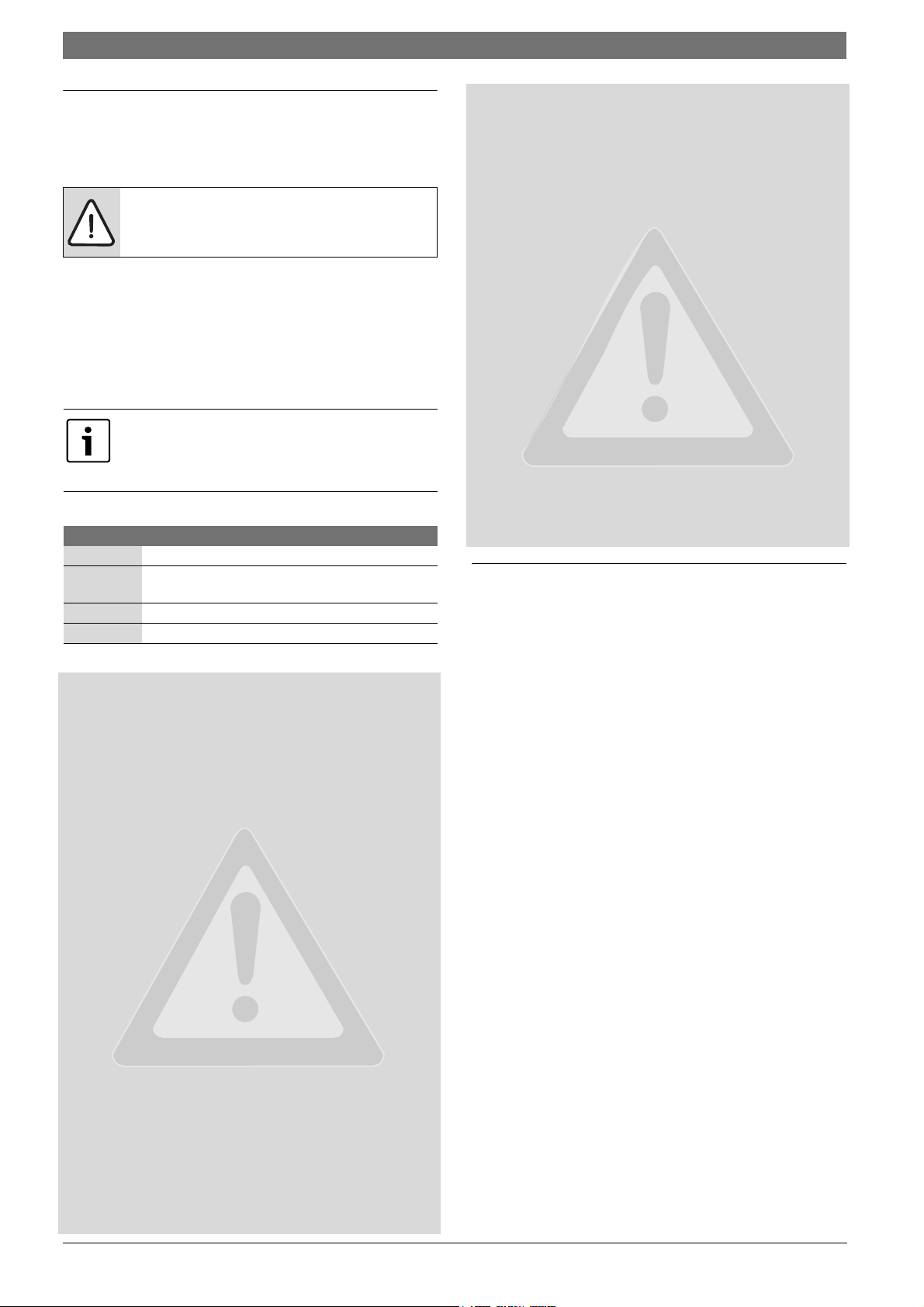
B Undo screws [1].
B Remove cover [2].
B Remove protective cap [3].
B Undo the screw connection.
B Remove the STB with its assembly plate and make the adjustments
(Æ chapter 3.1.2).
6 720 802 836 (2012/05)CFB 840
Page 6
6 | Setting instructions
1 1
2
3 2
Fig. 1 Remove the high limit safety cut-out
[1] Screws
[2] Cover
[3] STB protective cap
Set the high limit safety cut-out in accordance with local
regulations, applicable standards and the boiler
certificate to the maximum permissible heating system
temperature.
The factory setting is 110 °C.
3.1.2 Adjusting the high limit safety cut-out
CAUTION: System damage due to incorrect installation
of the STB at the boiler!
The sensor must be pushed into the sensor well as far as
possible to ensure a reliable and fast shutdown in case of
excesstemperature. Ensure an optimum heat transfer
from STB sensor to boiler. The sensors must be secured
in the sensor wells by means of the sensor locks
(standard delivery). The capillaries must not be
damaged or kinked.
B Verify the function of the STB before commissioning.
B Regular checks must be performed in accordance
with the boiler manufacturer's specifications.
DANGER: Risk to life and of system damage through
incorrect shutdown of the STB.
B Ensure that the STB is correctly shut down before
commissioning the boiler.
Special regulations and standards apply to boilers with
an STB setting of 120 °C. Boilers installed with an STB
setting higher than 110C have to meet specific
requirements.
Version A
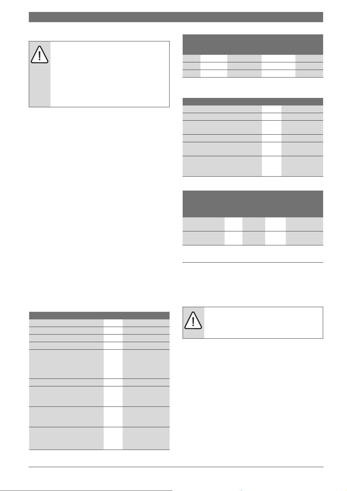
B Undo the screw [3].
B Adjust the temperature scale [2] to setting [1].
B Re-tighten screw [3].
6 720 803 704-03.1T
1
100
110
120
3
6 720 803 704-01.1T
Fig. 2 Adjusting the high limit safety cut-out (STB) - variant A
[1] Marking
[2] Temperature scale
[3] Screw
B Install STB into housing.
B Check the high limit safety cut-out (Æ chapter 6.2, page 13).
Version B
B Set the temperature using a screwdriver.
°C
100
110
120
6 720 803 704-12.1T
Fig. 3 Adjusting the high limit safety cut-out (STB) - variant B
B Install STB into housing.
B Check the high limit safety cut-out (Æ chapter 6.2, page 13).
3.2 Setting instructions for boiler water thermostat (TR)
Changing the boiler temperature controller from 90 °C to
105 °C (STB setting 120 °C only).
Control units may be operated with a maximum flow
temperature of 99 °C (Æ chapter 9.3.5, page 24).
For systems requiring a boiler water temperature higher than 90 °C
(observe the relevant notice), the boiler temperature controller setting
can be changed from 90 °C to 105 °C.
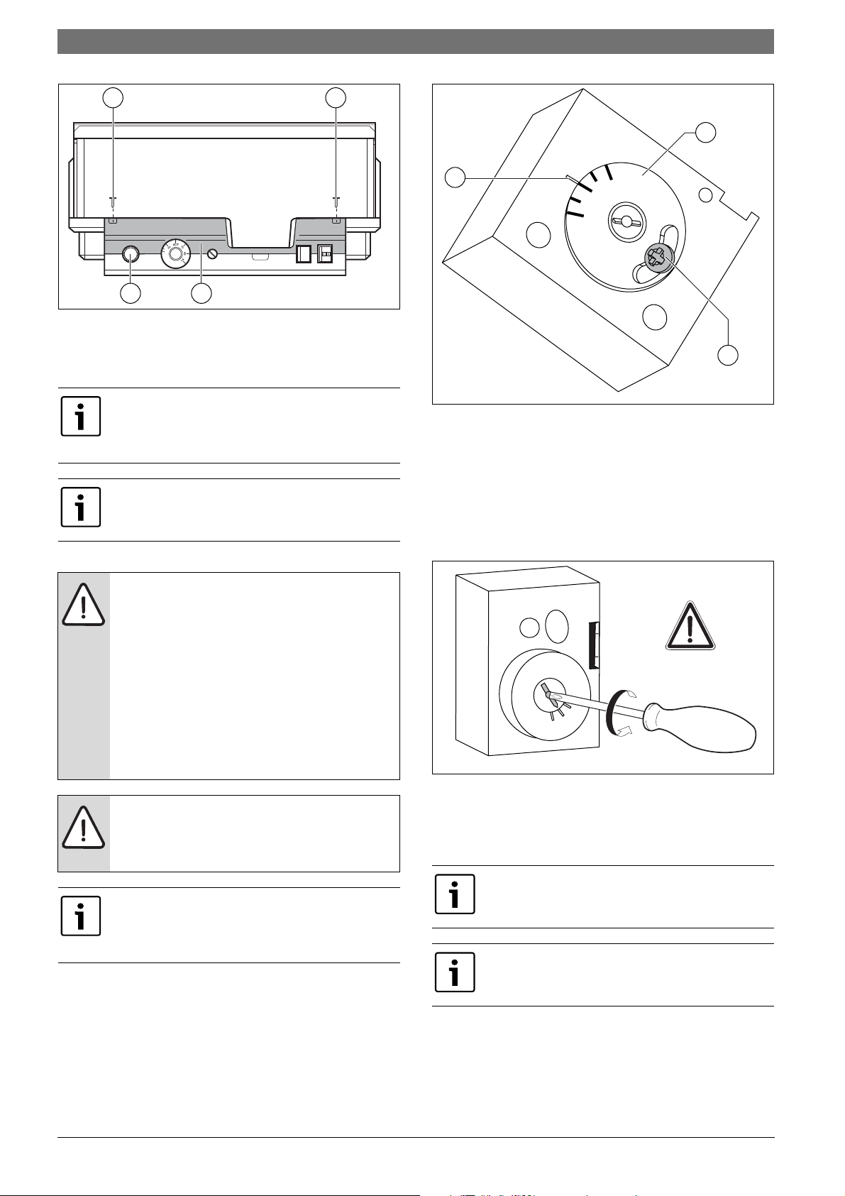
B Pull off rotary dial.
B Break off the end stop tabs [1].
CFB 8406 720 802 836 (2012/05)
Page 7
B Reposition rotary dial.
1
Fig. 4 Boiler water temperature controller
[1] End stop tabs
4 Controls and programming unit
4.1 Control unit controls
Controls and programming unit | 7
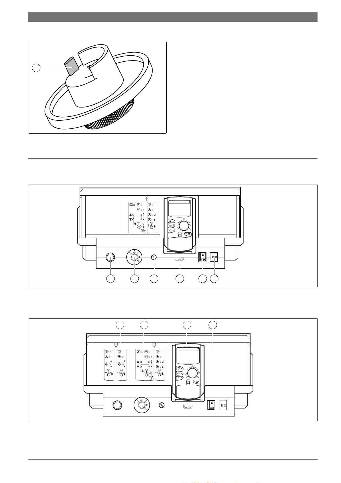
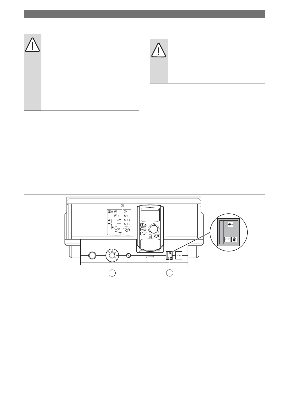
6 720 803 704-04.1T
1 2 3 4 5 6
Fig. 5 Control unit controls (delivered condition)
[1] High limit safety cut-out
[2] Boiler water temperature controller
[3] Fuse F1
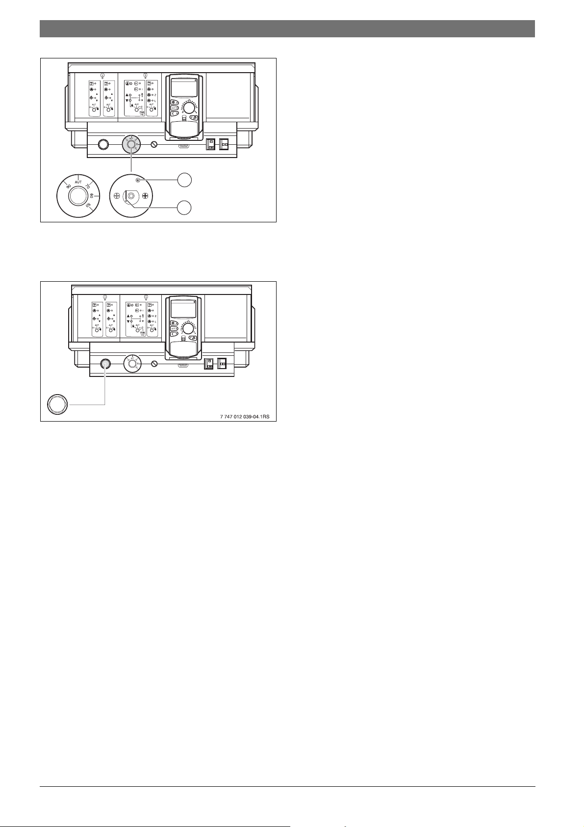
1 2 3 4
Fig. 6 Fitted modules
[1] Slot 1, e.g. FM442/CMM 920 - heating circuit 1, heating circuit 2
[2] Slot A: ZM422 - feed for external heat sources, heating circuit 0
6 720 803 704-05.1T
[4] Connection for external service equipment and programmer
[5] Burner emergency operation switch
[6] On/Off switch
6 720 803 704-06.1T
[3] Slot B: Programmer (CM431) - programming unit
[4] Slot 2, e.g. FM442/CMM 920 - heating circuit 3, heating circuit 4
6 720 802 836 (2012/05)CFB 840
Page 8

8 | Controls and programming unit
4.2 Programmer programming unit
17
16
1
15
14
13
12
11
10
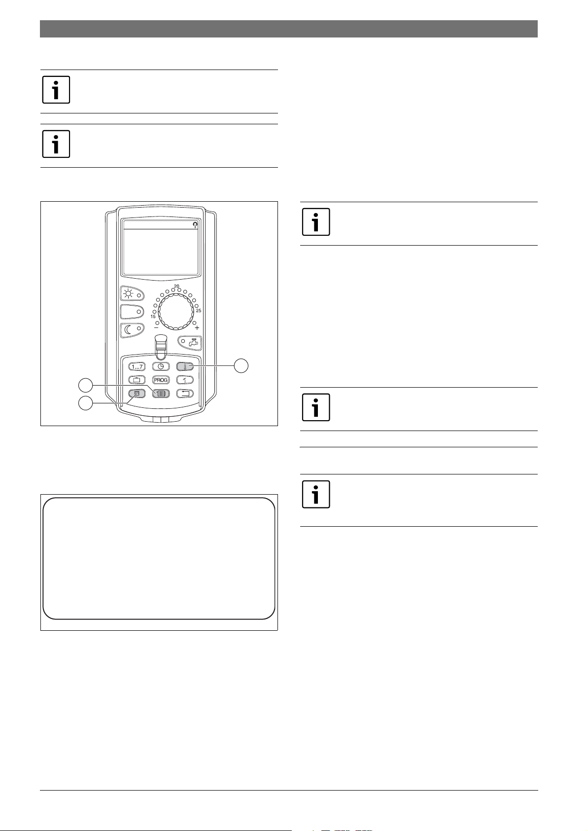
Fig. 7 Programmer programming unit
[1] Radio clock signal (only in Germany)
[2] Display for set room temperature
[3] Input DHW temperature/heating
[4] Setting the time
[5] Change temperature values
[6] Summer/wintertime changeover
[7] Back to the standard display
[8] Select a time switch program
[9] Selecting heating circuits/DHW circuit
9 8
2
3
4
5
6
7
6 720 803 703-04.1T
[10] Select standard display
[11] Enter holidays
[12] Enter the day of the week
[13] Constant setback mode
[14] Automatic heating mode in accordance with a time switch
[15] Constant heating mode
[16] Rotary dial
[17] Display
CFB 8406 720 802 836 (2012/05)
Page 9
Modules and their function | 9
5 Modules and their function
All modules which are or can be fitted into your CFB 840 control unit are
shown here.
The following pages contain information regarding the most important
modules you can use.
Module CFB 840
Programmer O
CM431 controller module O
Central module ZM422 – burner control,
1 heating circuit + 1 DHW circuit
Function module FM441/CMM 910 –
1 heating circuit + 1 DHW circuit
Function module FM442/CMM 920 - 2 DHW circuits X
Function module FM443/CMS 910 – solar circuit X
Function module FM444/CMG 910 –
alternative heat source
Function module FM445/CML 910 –
LAP/LSP (primary store system)
Function module FM448/CMB 930 –
central fault message
Expansion module ZM426/CME 920 – additional STB X
Function module FM458/CMC 930 – strategy module –
Table 6 Modules and their functions
O
–
X
X
X
Address Description
0 Stand-alone control unit:
Set the address to 0 if the control unit operates as standalone equipment (factory setting).
Each device must be given a different address if several
devices connected to the networked. A fault message is
displayed in the Programmer display if the same address is
allocated more than once.
1Master (lead control unit):
Address 1 is a special setting since the device with this
address acts as the master device. The master controls the
boiler.
The ambient temperature sensor must always be connected
to the master.
The master monitors the ECOCAN BUS, which links the
control units.
The master recognises if an address has been allocated
more than once. A fault message is displayed by the
Programmer display.
All networked control units transfer their set values to the
master, which uses them to formulate the overall
temperature setpoint.
Any network must only include one master.
2 – 15 Not applicable to CFB 840 control unit
Table 7 Control unit addresses
[O] Standard equipment
[X] Optional equipment
[ – ] Combination not possible
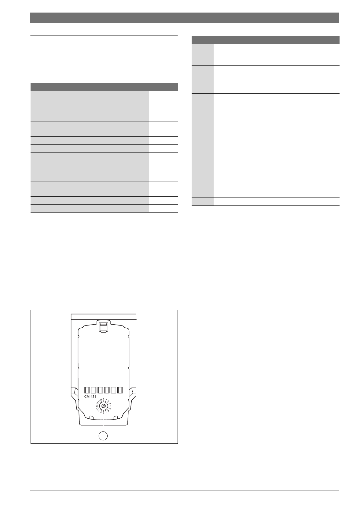
5.1 CM431 controller module
Setting the control unit address
The address settings [1] for the CFB 840 control unit are made on the
CM431 module (behind the programming unit).
B Remove the programming unit.
B You can now set th e control unit address using a screwdriver or similar
tool.
Fig. 8 Address setting
[1] Address setting
1
6 720 803 703-05.1T
6 720 802 836 (2012/05)CFB 840
Page 10
10 | Modules and their function
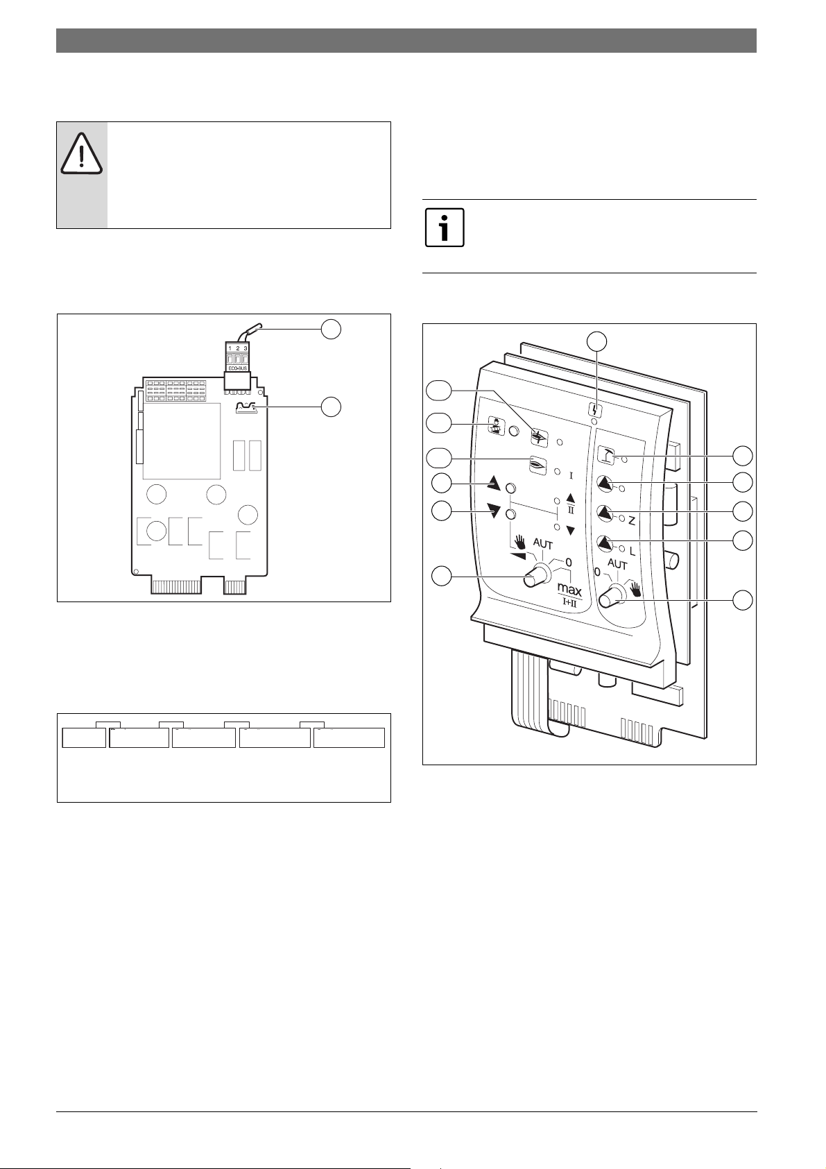
5.2 NM482 power supply module
End connection when networking several control units
DANGER: Risk to life from electric shock!
B Ensure that all electrical work is only carried out by a
competent person.
B Before opening the control unit, isolate all poles of the
control unit and secure against unauthorised reconnection.
To ensure fault free data transmission between several control units, fit
the end connections to the two control units which are furthest apart.
The end connection is fitted to the component side of the NM482 power
supply module, and is activated by the gravity switch (fig. 9, [2]).
1
2
5.3 Central module ZM422
The ZM422 module is part of the basic equipment of the CFB 840
control unit. The manual switches on the module are only provided for
service and maintenance functions.
If the manual switches are not set to automatic, a corresponding
message appears on the programming unit and the fault indicator
illuminates.
Never use the manual switch to shut down the heating
system during temporary absence. Use the holiday
function for this purpose (Æ operating instructions for
control unit).
The control functions remain operational in manual mode without any
restrictions.
1
12
11
10
9
2
3
6 720 803 703-06.1T
Fig. 9 NM482 power supply module
[1] ECOCAN BUS
[2] Gravity switch S1 (for end connection)
factory setting: open
The factory setting is: Gravity switch S1 open = end connection not
fitted.
Device
Device
Gerät
4...
4...
Fitting the
Widerstand
end connection
einlegen
Device
Gerät
4...
4...
4...
Device
Gerät
4...
4...
Device
Gerät
4...
4...
Device
Gerät
4...
4...
Fitting the
Widerstand
end connection
einlegen
6 720 803 703-07.1T
Fig. 10 Example of a fitted end connection, in case of several control
units
8
7
Fig. 11 ZM422
[1] General fault,
e.g. on-site faults, sensor faults, external faults, wiring faults,
internal module faults, manual mode. The error messages appear
as plain text in the programming unit.
[2] Boiler circuit 0 in summer mode
[3] Heating circuit 0 or boiler pump operational
[4] DHW circulation pump operational
[5] Cylinder primary pump operational
[6] Manual switch heating circuit and DHW
[7] Manual burner switch
[8] Modulating output is reduced
[9] Modulation output is increased/2nd stage operation
[10] Burner in operation
[11] "Flue gas test" button
[12] Burner fault
4
5
6
6 720 803 704-07.1T
CFB 8406 720 802 836 (2012/05)
Page 11
Modules and their function | 11
5.3.1 Burner function
Flue gas test
B Press and hold button Flue gas test (Æ fig. 11, [11], page 10) for a
few seconds.
The heating control unit operates for 30 minutes at a higher flow
temperature.
During the flue gas test, the indicators Fault and Summer mode flash
alternately.
To terminate the flue gas test:
B Press button Flue gas test again.
Manual burner switch
In normal operation, the manual switch is set to AUT.
Positions 0, Manual and max I + II of the burner's manual switch are
special settings (Æ fig. 11, [7], page 10) reserved for contractors.
The burner may be directly controlled with the manual switch.
Current functions are indicated by LEDs.
Position Function
AUT
0
max
I+II
As base load, only the first stage will be
enabled for single and two stage burners. The
second stage is at zero volts. The burner
servomotor cannot be reversed. For
modulating burners, the burner output can be
increased using S and reduced using T.
AUT
AUT
AUT
0
max
I+II
0
max
I+II
0
max
I+II
The burner operates in automatic mode.
The burner is switched OFF. Except when the
burner emergency switch is set to Manual.
The burner operates continuously at maximum
output.
Table 8 Burner functions ZM422
5.3.2 Heating circuit and DHW functions
Position Function
The heating circuit 0 pump or boiler pump and
the cylinder primary pump are switched on.
Heating circuit 0 pump or the boiler circuit and
DHW circuit operate in automatic mode.
Heating circuit 0 pump or boiler pump, the
cylinder primary pump and DHW circulation
pump are switched off. The control functions
remain active.
Table 9 Heating circuit and DHW functions ZM422
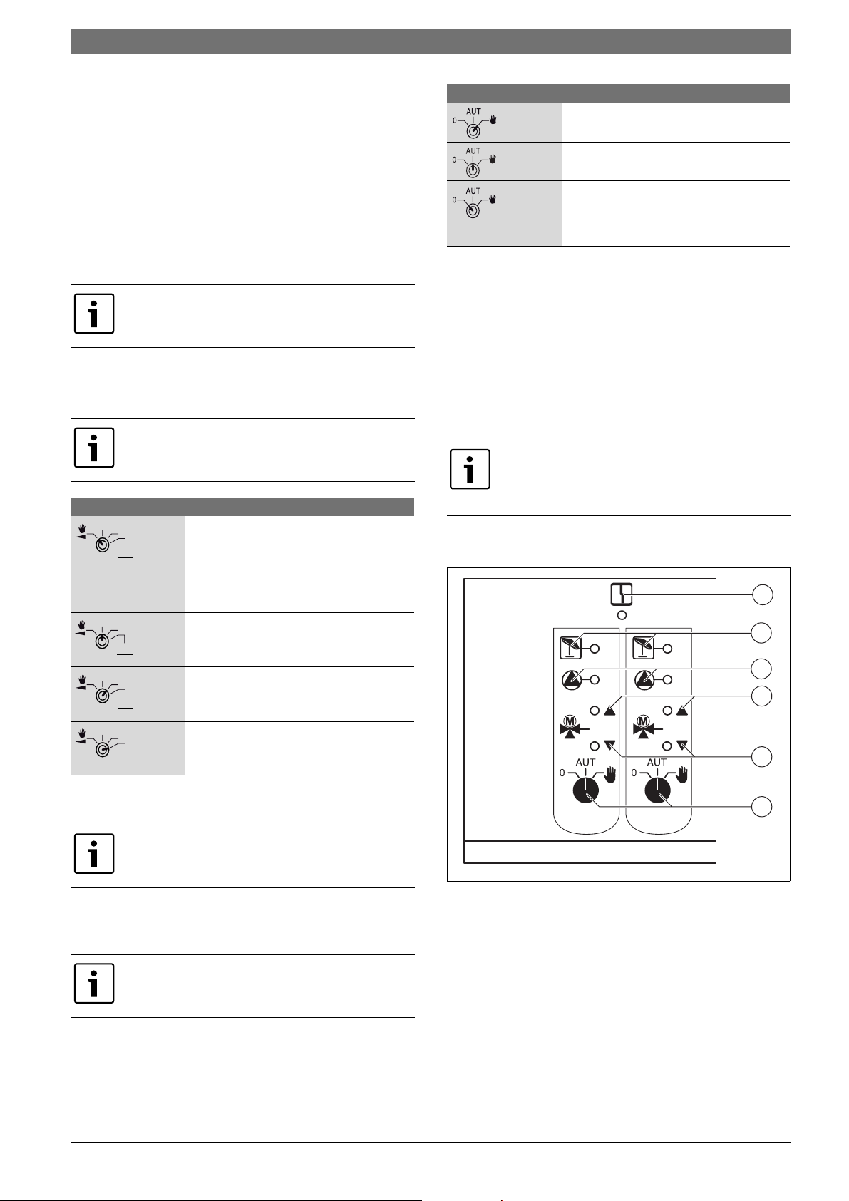
5.4 FM442/CMM 920 function module (accessory)
The FM442/CMM 920 module regulates two independent heating
circuits with optional mixing valves. Several of these modules can be
used in one control unit.
The manual switches on the module only have service and maintenance
functions and only affect 230 V outputs.
If the manual switches are not set to automatic, a corresponding
message appears on the programming unit, and the corresponding
indicator Fault illuminates.
Never use the manual switch to shut down the heating
system during temporary absence. Use the holiday
function for this purpose (Æ see operating instructions
for control units).
The control functions remain operational in manual mode without any
restrictions.
1
2
3
4
5
6
In normal operation, the manual switch is set to AUT.
Positions 0 and Manual are special settings of the manual switch for the
heating circuit and DHW (Æ fig. 11, [6], page 10) reserved to
contractors.
Current functions are indicated by LEDs.
6 720 803 703-13.1T
Fig. 12 FM442/CMM 920
[1] General fault,
e.g. on-site faults, sensor faults, external faults, wiring faults,
internal module faults, manual mode. The error messages appear
as plain text in the programming unit.
[2] Heating circuit in summer mode
[3] Heating circuit pump operational
[4] "Mixing valve opens" (hotter)
[5] "Mixing valve closes" (colder)
[6] Manual heating circuit switch
e.g. for heating circuit 1 and 2
6 720 802 836 (2012/05)CFB 840
Page 12
12 | Commissioning
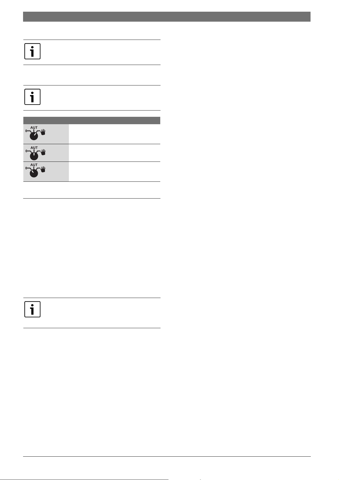
Heating circuit function
In normal operation the manual switch should be in the
AUT position.
Positions 0 and Manual are special settings of the manual switch for the
heating circuit (Æ fig. 12, page [6]) reserved to contractors.
Current functions are indicated by LEDs.
Position Function
The heating circuit pump is switched on. The
mixing valve is switched volt-free and can be
manually operated.
The central heating or the DHW circuit
operates in automatic mode.
The heating circuit pump is switched off. The
mixing valve is switched volt-free. The control
functions remain active.
Table 10 Heating circuit functions FM442/CMM 920
6 Commissioning
6.1 Commissioning the programming unit
The programming unit can be used with all control units of the series 7xx,
8xx and 9xx.
The programming unit can be used as follows:
• directly in the control unit
• wall-mounted as remote control unit or
• in an adapter with separate power source.
The Programmer starts the initialisation process as soon as supply
voltage is connected. The display shows MEC is initialised.
The control unit address is then briefly displayed.
The display shows Connection with ctrl. unit Address xx established.
If the Programmer is fitted in the control unit or wall
mounting plate, it automatically detects the control unit
to which it is connected (automatic detection). You do
not have to select the control unit.
Depending on the individual application, the display shows various
information:
6.1.2 Programmer is installed in another control unit
If the Programmer is programmed with a software version that is not able
to recognise this type of control unit, the display shows Unknown
control unit.
B Remove the Programmer from the control unit and replace by a
Programmer with a suitable software version.
6.1.3 Programmer with set parameters installed in control unit
After the Programmer has been installed in the control unit, the two
adjacent displays will initially be re-displayed. MEC is initialised or
Connection with ctrl. unit Address xx established.
Alternative control unit type
Initially, only data from the control unit can be downloaded, if the type of
control unit varies from that entered in the programming unit. The
display shows Other Ctrl. unit type, Night button receive.
B Press the Night mode button.
The display shows Data are from ctrl unit taken.
Alternative control unit of the same type
If the Programmer is connected to a different control unit of the same
type, the display will show the below message for approx. 3 seconds.
NB other control unit.
If the Programmer programming unit is separated from the control unit
and data is modified, the display shows Aut button transmit, Night
button receive, when the unit is reinstalled into a control unit of the
same type. The control unit scans whether the new data should be
accepted or whether the old data from the control unit should be used
again.
To adopt the new data:
B Press AUT.
The display shows Data are to ctrl unit sent.
To adopt the data from the control unit:
B Press the Night mode button.
The display shows Data are from ctrl unit taken.
Identical control unit
If the programming unit is separated from the control unit and data is
modified externally, the display shows
button receive, when the unit is reinstalled into a control unit of the
same type. The control unit scans whether the new data should be
accepted or whether the old data from the control unit should be used
again.
To adopt the new data:
B Press AUT.
The display shows Data are to ctrl unit sent.
To adopt the data from the control unit:
B Press the Night mode button.
The display shows Data are from ctrl unit taken.
Aut button transmit, Night
6.1.1 New Programmer installed in a control unit
If a brand new Programmer has been installed in the control unit and the
connections with the control unit have been established, data are
immediately downloaded from the control unit.
The display shows Monitor data will from ctrl unit taken.
CFB 8406 720 802 836 (2012/05)
Page 13
6.2 Checking the high limit safety cut-out (STB)
CAUTION: System damage due to incorrect installation
of the STB at the boiler!
The sensor must be pushed into the sensor well as far as
possible to ensure a reliable and fast shutdown in case of
excesstemperature.
B Ensure an optimum heat transfer from STB sensor to
boiler.
B The sensor must be secured in the sensor well by
means of the sensor locks (standard delivery).
B Ensure that capillaries are not damaged or kinked.
B Verify the function of the STB before commissioning.
B Regular checks must be performed in accordance
with the boiler manufacturer's specifications.
The boiler temperature must be monitored continuously at the
programmer or at the boiler display of the ZM435 or at suitable
measuring points while performing the STB check.
The burner must shut down automatically when the set cut-out
temperature (chapter 3) of the STB + 2K (example 110 °C + 2K =
112 °C) is reached. If the burner does not shut down at this point,
manually interrupt the checking procedure at once. To shut down,
release the lever of button and switch the emergency mode switch of the
burner to AUT.
After interrupting the checking procedure, check the correct routing of
the capillaries and the temperature sensor head as well as the assembly
and wiring of the boiler water temperature sensor. When in doubt,
assume the STB to be broken. In this case the broken high limit safety
cut-out must be replaced.
Commissioning | 13
6.2.1 Triggering the high limit safety cut-out
DANGER: Risk to life through boiler excesstemperature!
Never perform the STB test without supervision.
B Immediately interrupt the test if the set STB
temperature is exceeded.
B Release the lever or button (depending on controller
type) of the temperature controller.
B Set burner emergency switch to AUT.
B Set burner emergency switch [2] Manual.
The burner starts.
B Pull off the thermostat selector dial [1].
B Depending on the type of controller, push the lever or button
(Æ fig. 14) back with a screwdriver or similar tool and hold until
the high limit safety cut-out has triggered.
B Continuously monitor the boiler temperature, and interrupt the test,
if required.
6.2.2 Terminating or cancelling the test
B Set burner emergency switch (Æ fig. 13, [2]) to AUT.
B Depending on controller type, release the lever or button (Æ fig. 14,
page 14).
B Push on the button of the temperature controller (Æ fig. 13, [1]).
B Set controllers, switches and thermostats to the equipment-specific
conditions.
B Set the temperature controller to AUT.
1
Fig. 13 Checking the STB using the burner emergency operation switch
[1] Thermostat selector button
[2] Burner emergency operation switch
6 720 803 704-10.1T
2
6 720 802 836 (2012/05)CFB 840
Page 14
14 | Commissioning
1
2
Fig. 14 Triggering the high limit safety cut-out
[1] Key
[2] Lever
6.2.3 Resetting the high limit safety cut-out
Fig. 15 Resetting the high limit safety cut-out
B Undo the cap.
B Push the reset button underneath.
B Refit the cap.
6 720 803 704-09.1T
CFB 8406 720 802 836 (2012/05)
Page 15

7 Settings
7.1 Adjustable parameters and display data
Some options are only displayed subject to the installed modules and
prior settings.
General parameters External Day/Night/Aut
Minimum outside temperature External fault message - pump
Type of building Screed drying
Summer/winter time adjustment Screed temperature rise
Remote adjust. Screed heat-up time
Heat yield Maximum screed temperature xxxx
Level limit transducer Maximum screed time
Fault message manual control Screed setback temperature
Automatic maint. message Screed setback time
Module selection Heating circuit 0, 2, 3, 4 see heating circuit 1
Slot A DHW
Slot 1 DHW yes/no
Slot 2 DHW range to
Boiler param. Switching optimisation
Boiler type Residual heat use
Fuel Hysteresis
Ecostream control Boiler raising
Type of burner External fault message WF1/WF2
Sequence reversal after ... Hours External contact WF1/WF3
Minimum modulation output Thermal disinfection
Burner set motor runtime Thermal disinfection temperature
Load limit from outside temperature Thermal disinfection weekday
Boiler pump function Thermal disinfection time
Boiler pump run-on time Daily heat-up
Minimum burner runtime DHW circulation (start frequency pe
Pump logic temperature Special parameters
Minimum start temperature Heating characteristics
Maximum shutdown temperature Heating curve heating circ. 0
Flue gas temperature limit Heating curve heating circ. 1
Heating curve heating circ. 2Heating circ. 1
Heating system Heating curve heating circ. 3
Heat. circ. desig.
Low end temp. Relay test
Design temperature Boiler
Minimum flow temperature Heating circ. 0
Maximum flow temperature Heating circ. 1
Remote control Heating circ. 2
Maximum room infl Heating circ. 3
Setback type Heating circ. 4
Outside hold frm. DHW
Holiday setback type LCD test
No setback below ... Fault
Flow setback Monitor
Room temperature offset Boiler
Automatic adaptation Heating circ. 0
Switching optimisation Heating circ. 1
Stop optimisation Heating circ. 2
Frost prot from Heating circ. 3
DHW priority Heating circ. 4
Servomotor (not on heating circuit 0) DHW
Servomotor runtime Version
Boiler raising Control unit
Heating curve heating circ. 4
Reset
Control unit settings
Burner Hours run
Fault log
Maximum flue gas temperature
Heat yield
Maint. message
Settings | 15
r hour)
Fig. 16 Adjustable parameters and display data
6 720 802 836-08.1TL
6 720 802 836 (2012/05)CFB 840
Page 16
16 | General specification data
7.2 Calling up the service level
Access to the Service level is password protected. The
Service level is only intended for heating contractors.
Unauthorised access to the service level invalidates your
warranty.
B Press buttons Display, Heating circuit and Temp simultaneously and
release.
AUT
1
3
2
6 720 803 703-18.1T
Fig. 17 Calling up the service level
[1] Temperature key
[2] Display key
[3] Heating circuit key
The service level is enabled and the display shows:
• GENERAL PARAM.
• Module selection
• ...
• GENERAL PARAM.
7.2.3 Calling up submenus
B Turn the rotary dial until the main menu containing the submenu is
highlighted.
B Press button Display.
The submenu is shown.
B Turn the rotary dial to access all submenus of the main menu.
7.3 Calling up and modifying settings
The menus displayed on the programming unit of the
control unit depend on which modules are fitted and on
their settings.
B Calling up the service level (Æ chapter 7.2, page 16).
GENERAL PARAM. appears as the first main menu.
B Press Display to call up a submenu.
The display shows the selected submenu.
B Press and hold Display.
B Turn the rotary dial to the required value.
The display shows the set value.
B Release Display to save your input.
B Press Back to return to the next higher level.
To return to the standard display:
B Press Back several times.
The control unit automatically reverts to the standard
display if no key is pressed for some time or if the flap is
shut.
8 General specification data
In main menu GENERAL PARAM. values can be adjusted
for the submenus listed above and the building
characteristics. The following pages explain how to
adjust values relating to the submenus.
SERVICE LEVEL
Gen. Parameters
6 720 802 836-19.1TL
Fig. 18 Service level
7.2.1 Control system "Press and turn"
The control unit is controlled by pushing the buttons or turning the rotary
dial.
The Service level is split over several main menu levels. If the last line is
left blank (without value entry), there are further submenus connected
to the main menu selected.
7.2.2 Calling up main menus
The rotary dial is used to scroll through the main menu. The main menus
are structured as a loop and recommence after the last main menu.
B Call up the service level.
GENERAL PARAM. appears as the first main menu.
B Press Display to call up a submenu.
B Turn the rotary dial until the required submenu is shown.
Turn the rotary dial to scroll through the following submenus:
• Minimum outside temperature
• Type of building
• Summer/wintertime changeover
• Remote adjust.
• Amount of heat
• Manual fault message control
• Automatic maint. message
B Press button Display to call up a submenu.
The display shows the selected submenu, and settings can be made.
CFB 8406 720 802 836 (2012/05)
Page 17
General specification data | 17
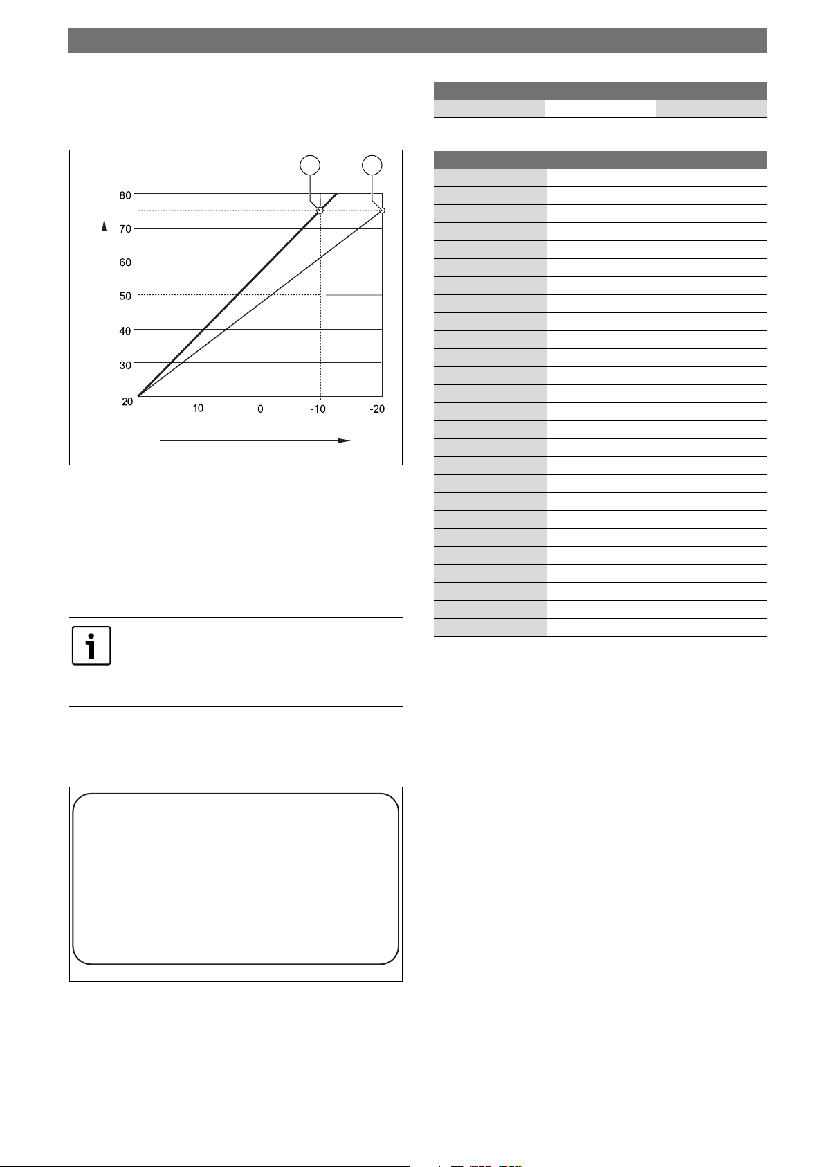
8.1 Minimum outside temperature
The minimum outdoor temperature is an average value of the lowest
outdoor temperatures of the past years and defines together with the
design temperature the end point of the heating curve.
1 2
[°C]
A
T
T
minA
Fig. 19 Heating curve adjustment: Adjustment of gradient via design
temperature and minimum outside temperature
] Minimum outside temperature
[T
minA
] Design temperature (flow temperature that should be achieved
[T
A
at min. outside temperature)
[1] Adjustment: Design temperature 75 °C, minimum outside
temperature –10 °C (standard curve)
[2] Adjustment: Design temperature 75 °C, minimum outside
temperature –20 °C
The minimum outside temperature for your region
(average value) is stated in tab. 12. If your particular
region is not shown in the table, set an average value
between the two cities closest to you or take the value
from the heat demand calculation for your building.
[°C]
6 720 803 703-21.1T
Input range Factory setting
Min outdoor temp -30 °C – 0 °C -10 °C
Table 11 Setting range Minimum outside temperature
Town Minimum outside temperature in °C
Athens –2
Berlin –15
Brussels –10
Budapest –12
Bucharest –20
Frankfurt/M –14
Hamburg –12
Helsinki –24
Istanbul –4
Copenhagen –13
Lisbon 0
London –1
Madrid –4
Marseilles –6
Moscow –30
Munich –16
Naples –2
Nice 0
Paris –10
Prague –16
Rome –1
Sevastopol –12
Stockholm –19
Valencia –1
Vienna –15
Zurich –16
Table 12 Minimum outside temperature in Europe
B Call up the service level.
GENERAL PARAM. appears as the first main menu.
B Press Display to call up a submenu.
B Turn the rotary dial until submenu Min outdoor temp is displayed.
GENERAL PARAM.
Min outdoor temp
o
-10
6 720 802 836-20.1TL
Fig. 20 Minimum outside temperature
B Hold down button Display and turn the rotary dial until the required
value is shown.
The display shows the set value.
B Release Display to save your input.
B Press Back to return to the next higher level.
C
6 720 802 836 (2012/05)CFB 840
Page 18

18 | General specification data
8.2 Type of building
In submenu Type of building the heat storage capacity of the building is
entered. Different types of construction have different heat storage
capacities. This function sets the heating system to the specified
construction type.
The heat storage capacity is divided into three categories.
Class Explanation
light heat storage capacity
e.g. prefabricated building, wood-frame
construction
medium medium heat storage capability,
e.g. house built with breeze blocks
heavy heat storage capacity
e.g. brick house
Table 13 Heat storage capacity
B Call up the service level.
GENERAL PARAM. appears as the first main menu.
B Press Display to call up a submenu.
B Turn the rotary dial until submenu Type of building is displayed.
B Hold down button Display and turn the rotary dial until the required
value is shown.
The display shows the set value.
B Release Display to save your input.
B Press Back to return to the next higher level.
When using the Programmer as remote control, the reception of the
radio clock signal depends on each location and position. Reception of
the radio clock signal is indicated by a symbol on the display (Æ fig. 7,
[1], page 8). Normally, reception is possible within a radius of approx.
1000 miles around Frankfurt/Main [Germany].
In case of reception problems, please observe the following:
• The radio reception is weaker in rooms surrounded by steelreinforced walls, cellars, high-rise buildings etc.
• Maintain a minimum distance of 1.5 m from sources of interference,
such as computer monitors and TV sets.
• The radio reception tends to be better at night than during the day.
B Call up the service level.
GENERAL PARAM. appears as the first main menu.
B Press Display to call up a submenu.
B Turn the rotary dial until submenu Summer / Winter
Time changeover is displayed.
B Hold down button Display and turn the rotary dial until the required
value is shown.
The display shows the set value.
GENERAL PARAM.
Summer / Winter
Input range Factory setting
Type of building medium
heavy
light
Table 14 Setting range Building type
medium
8.3 Summer/wintertime changeover
Three different date and time setting options are available for all
connected control units:
Setting
options
Radio clock The adjustment is made completely automatically by
Automatic Date and time input with keypad. The change from
Manual Single date and time input via keypad. There will be no
Table 15 Setting options Date and time
Explanation
the radio time signal.
summer to winter time and vice versa is made
automatically on the last weekend in March and
October.
automatic summer/wintertime adjustment.
The Programmer contains a radio receiver, which
constantly monitors and corrects the time switch inside
the control unit. You never need to set the time during
commissioning, after prolonged power failure, after the
heating system has been switched off for longer periods
on its mains electrical isolator or for changing from
summer to winter time and vice versa.
Well screened boiler rooms in cellars can restrict the
reception of the radio clock signal, which makes it
necessary for you to set the date and time manually.
Time changeover
Radio clock
Fig. 21 Summer/winter time changeover
B Release Display to save your input.
B Press Back to return to the next higher level.
If not Radio clock is selected, the reception of the
atomic clock signal will be turned off for all networked
control units. This also applies to the radio time signals of
the BFU/F remote control and other programming units
with radio clock reception. The last input at a control unit
in the network is valid.
Input range Factory setting
Summer/winter
Time changeover
Table 16 Setting range Summer/winter time changeover
Radio clock
automatic
manual
Automatic
6 720 802 836-22.1TL
Do not enable the "Radio clock" function outside
Germany.
CFB 8406 720 802 836 (2012/05)
Page 19

General specification data | 19
8.4 Remote adjust
The remote adjustment offers the option of external data entry and
adjustment via a remote system.
Setting
options
yes Optional remote adjustment via the telecontrol system
no Remote adjustment is not possible, but system data
Table 17 Setting options Remote adjustment
B Call up the service level.
GENERAL PARAM. appears as the first main menu.
B Press Display to call up a submenu.
B Turn the rotary dial until submenu Remote adjust. is displayed.
B Hold down button Display and turn the rotary dial until the required
value is shown.
The display shows the set value.
B Release Display to save your input.
B Press Back to return to the next higher level.
Remote adjust. yes
Table 18 Setting range Remote adjustment
Explanation
can be downloaded and monitored.
This parameter cannot be adjusted via the telecontrol
system; it is only intended to be changed in situ.
Input range Factory setting
yes
no
8.5 Manual fault message control
A fault message can be shown in the display of the programming unit
when the manual switch of the function module is set to Manual.
B Call up the service level.
GENERAL PARAM. appears as the first main menu.
B Press Display to call up a submenu.
B Turn the rotary dial until submenu Fault message manual control is
displayed.
B Hold down button Display and turn the rotary dial until the required
value is shown.
The display shows the set value.
If No is shown, a warning notice appears if the flap is
closed.
If Fault message is shown, an entry also appears in the
fault log. Automatic forwarding via the CFB 840
telecontrol system is then possible.
If cent. fault mess is shown, the out put of a central fault
message also appears via a volt free contact e.g. via the
FM448/CMB 900-0-10V function module.
Input range Factory setting
Fault message
manual control
Table 19 Setting range Manual switch fault message
No
Fault message
central fault message
no
8.6 Automatic maint. message
At the user level an automatic maintenance message to appear on the
programming unit display can be generated.
The following settings are possible:
• Maintenance message by date. Entry of the date of the next service
date (01.01.2000 – 31.12.2088).
• Maintenance after hours run (only for control units with direct boiler
control).
The maintenance message "after hours run" is not
possible with this control unit.
B Call up the service level.
GENERAL PARAM. appears as the first main menu.
B Press Display to call up a submenu.
B Turn the rotary dial until submenu automatic maint. message is
displayed.
B Hold down button Display and turn the rotary dial until the required
value is shown.
The display shows the set value.
GENERAL PARAM.
GENERAL PARAM.
Fault message
manual control
Fault message
Fig. 22 Manual fault message control
B Release Display to save your input.
B Press Back to return to the next higher level.
automatic
maint. message
Date
6 720 802 836-24.1TL
Fig. 23 Automatic maint. message
B Release Display to save your input.
B Turn the rotary dial one increment clockwise.
6 720 802 836-23.1TL
6 720 802 836 (2012/05)CFB 840
Page 20

20 | Boiler parameters
B Hold down button Display and turn the rotary dial until the required
value is shown.
The display shows the set value.
MODULE SELECTION
GENERAL PARAM.
maint. message
on
01.10.2012
6 720 802 836-25.1TL
Fig. 24 Setting the automatic service date
B Release Display to save your input.
B Press Back to return to the next higher level.
The maintenance message is recorded in the fault log
and can be transferred via the CFB 840 telecontrol
system.
The status of the maintenance message can be scanned in menu
Monitor. The maintenance message can be reset in menu Reset.
Input range Factory setting
automatic
maint. message
Table 20 Setting range Automatic maintenance message
8.7 Module selection
On starting the control units or after a system reset, the modules are
automatically recognised and their information downloaded.
Example:
• Slot 1: ZM424
• Slot 2: free
However, these modules can also be set manually if required.
B Call up the service level.
GENERAL PARAM. appears as the first main menu.
B Turn the rotary dial until main menu Module selection appears.
B Press Display to call up a submenu.
B Turn the rotary dial until submenu Pos. 1 is displayed.
B Hold down button Display and turn the rotary dial until the required
value is shown.
The display shows the set value.
Recommended setting: Function module none/auto.
The modules are automatically recognised and installed.
No
Operating hours
Date
no
Pos. 1
Function module
none/auto
6 720 802 836-29.1TL
Fig. 25 Module selection
B Release Display to save your input.
B Press Back to return to the next higher level.
9 Boiler parameters
9.1 Select boiler type
Subject to the selected boiler type, special setting options will be
displayed. For further information regarding the setting of boilerspecific parameters, see Æ chapter 23.2, page 50.
B Call up the service level.
GENERAL PARAM. appears as the first main menu.
B Turn the rotary dial until main menu Boiler param. appears.
B Press Display to call up a submenu.
Boiler type appears as the first main menu. The display shows the set
value.
B Hold down button Display and turn the rotary dial until the required
value is shown.
B Release Display to save your input.
B Press Back to return to the next higher level.
Input range Factory setting
Boiler type Low temperature
Ecostream
Condensing
LT/Base line
temperature
Table 21 Setting range Boiler type
9.1.1 Low temperature boilers
The low temperature boiler is operated with a factory-set pump logic,
which depends on the selected burner type.
Setting the pump logic temperature
The heating circuit circulation pumps and, if installed, the boiler circuit
pump are switched on and off to maintain the boiler operating conditions
subject to the pump logic temperature. The preset pump logic
temperature only needs to be changed in special cases and is only
adjustable in case of boiler type = low temperature.
The factory-set pump logic temperature is 5 K below the minimum
shutdown temperature of the boiler.
B Call up the service level.
GENERAL PARAM. appears as the first main menu.
B Turn the rotary dial until main menu Boiler param. appears.
B Press Display to call up a submenu.
B Turn the rotary dial until submenu Pump logic temperature appears.
B Hold down button Display and turn the rotary dial until the required
value is shown.
B Release Display to save your input.
B Press Back to return to the next higher level.
Low temperature
CFB 8406 720 802 836 (2012/05)
Page 21

Boiler parameters | 21
Input range Factory setting
Pump logic
temperature
15°C–60°C 1-stage: 40 °C
2-stage: 45 °C
modulating: 50 °C
Table 22 Setting range Pump logic temperature
9.1.2 Ecostream boilers
The boiler operating conditions for the Ecostream boilers are set at the
factory and are automatically taken into account. Menu item Ecostream
control via is used to ascertain how the boiler operating temperature
should be controlled.
The factory setting provides a boiler operating temperature of 50 °C. The
minimum set value for the boiler flow temperature is 4 K higher (54 °C).
With the setting Heating circuit actuator the heating circuit circulation
pump starts 5 K below the boiler operating temperature and stops 7 K
below.
Ecostream control via
This setting determines via what servomotor the preset operating flow
temperature should be regulated. The setting must be made in
accordance with the existing or planned hydraulic conditions. It affects
the control of the respective servomotor and the pre-determined set
values.
Select from the following options:
• Heat. circ. act.
must be selected if the Ecostream is to be regulated by superimposed
actuation of the heating circuit actuators (three-way mixing valves).
Heating circuits must be equipped with mixing valves that are
regulated by heating circuit modules of the same CFB series (no third
party-controllers). The control function is designed for an actuator
runtime of 120 s.
• Ext. control
must be selected if the Ecostream is to be regulated by an external
control unit, e.g. if the CFB 840 does not need to fulfil any operating
conditions, for example in dual-block boiler systems with integral
control unit for regulating the annular butterfly valves of the boiler
blocks.
Setting the Ecostream control
B Call up the service level.
GENERAL PARAM. appears as the first main menu.
B Turn the rotary dial until main menu Boiler param. appears.
B Press Display to call up a submenu.
B Turn the rotary dial until submenu Ecostream control via appears.
B Hold down button Display and turn the rotary dial until the required
value is shown.
B Release Display to save your input.
B Press Back to return to the next higher level.
Input range Factory setting
Ecostream control via Act. heat.circ..
Act. circ.act.
Ext. Control
Table 23 Setting range Ecostream control
Set the actuator run-time
The actuator runtime is preset and should generally not be changed.
Incorrect entries may lead to fluctuating flow
temperatures during operation.
B Call up the service level.
GENERAL PARAM. appears as the first main menu.
B Turn the rotary dial until main menu Boiler param. appears.
B Press Display to call up a submenu.
B Turn the rotary dial until submenu Actuator runtime appears.
B Hold down button
Display and turn the rotary dial until the required
value is shown.
B Release Display to save your input.
B Press Back to return to the next higher level.
The runtimes of the heating circuit actuators are entered separately
under parameter Heat.circuit. If the runtimes of the individual heating
circuit actuators are different, a representative value (average) must be
entered.
Input range Factory setting
Actuator runtime 10 s – 600 s 120 s
Table 24 Setting range Actuator runtime
9.1.3 Condensing boiler
Boiler type Condensing must be selected if a condensing boiler has
been installed. No operating conditions need to be maintained for this
type of boiler.
9.1.4 Low-temperature boilers with base temperature
The respective factory-set operating conditions selected in the control
unit automatically apply when selecting this boiler type. An actuator
regulates the boiler operating temperature in the boiler flow. These set
values always apply, if a load demand exists for the boiler via a
consumer, irrespective of whether the burner is switched on or off. To
support the operating temperature control, the heating circuit
circulation pumps and the boiler circuit pump are switched off, if the
actual temperature falls below the defined minimum temperature.
The LT/base point temp. must be controlled via the
heating circuit actuators.
Setting the fuel type
Set the fuel to be used in this parameter. This setting influences the set
value for the servomotor and burner control. Factory settings default
Gas lower set values for the low end temperature apply when changing
the setting to oil.
B Call up the service level.
GENERAL PARAM. appears as the first main menu.
B Turn the rotary dial until main menu Boiler param. appears.
B Press Display to call up a submenu.
B Turn the rotary dial until submenu Fuel appears.
B Hold down button Display and turn the rotary dial until the required
value is shown.
B Release Display to save your input.
B Press Back to return to the next higher level.
Input range Factory setting
Fuel Gas
Oil
Table 25 Setting range Fuel
Gas
6 720 802 836 (2012/05)CFB 840
Page 22

22 | Boiler parameters
9.2 Setting the burner type
Additional setting masks will be displayed subject to the selected burner
type.
Select from the following options:
• Single stage
• two-stage
• Modulating
• 2xSingle-stage
This setting must be used in the following cases:
– For a boiler sequence comprising two single stage boilers that are
operated with only one CFB 840 on the 1st boiler and a constant
control unit on the 2nd boiler.
– For certain dual block boilers, each equipped with two single stage
burners, which operate independently of each other.
B Call up the service level.
GENERAL PARAM. appears as the first main menu.
B Turn the rotary dial until main menu Boiler param. appears.
B Press Display to call up a submenu.
B Turn the rotary dial until submenu Type of burner appears.
B Hold down button Display and turn the rotary dial until the required
value is shown.
B Release Display to save your input.
B Press Back to return to the next higher level.
Input range Factory setting
Type of burner single-stage
two-stage
modulating
2xsingle-stage
Table 26 Setting range Burner type
9.2.1 Modulating burner
Minimum modulation output Setting
The Minimum modulation output is that part of the total output, down
to which the burner can be modulated. The burner will be completely
switched off if the demand falls below this set value. Incorrect settings
can lead to control fluctuations.
B Call up the service level.
GENERAL PARAM. appears as the first main menu.
B Turn the rotary dial until main menu Boiler param. appears.
B Press Display to call up a submenu.
B Turn the rotary dial until submenu Minimum Modulation appears.
B Hold down button Display and turn the rotary dial until the required
value is shown.
B Release Display to save your input.
Input range Factory setting
Minimum Modulation 10%...60% 30%
Table 27 Setting range Minimum modulation
Single stage
Burner set motor runtime setting
The setting Burner set motor runtime tells the control unit the time
required by the burner servomotor for the movement between "closed"
and "open".
B Turn the rotary dial until submenu Burner sett. motor runtime
appears.
B Hold down button Display and turn the rotary dial until the required
value is shown.
B Release Display to save your input.
B Press Back to return to the next higher level.
Input range Factory setting
Burner sett.
5s–60s 12 s
motor runtime
Table 28 Setting range Burner set motor runtime
9.2.2 2 x single stage burner
Lead-lag acc. to ... Set Hours
This options allow the selection of the number of hours after which the
sequence with the 2 x single stage boiler blocks is reversed.
B Call up the service level.
GENERAL PARAM. appears as the first main menu.
B Turn the rotary dial until main menu Boiler param. appears.
B Press Display to call up a submenu.
B Turn the rotary dial until submenu Lead-Lag acc. to appears.
B Hold down button Display and turn the rotary dial until the required
value is shown.
B Release Display to save your input.
Input range Factory setting
Lead-lag acc. to ...
Hours
00, 10, 20, ... 1000
hours
00 hours
Table 29 Setting range Lead-lag/rotat after ... hours
Load limit
If burner type 2 x single-stage is selected, an outside temperature can
be specified under parameter Load limit, from which stage 2 will be
automatically blocked.
Example: From a certain outside temperature upwards, operation will
be limited to one boiler stage or one boiler block.
B Turn the rotary dial until submenu Load limit from outside T.
appears.
B Hold down button Display and turn the rotary dial until the required
value is shown.
B Release Display to save your input.
B Press Back to return to the next higher level.
Input range Factory setting
Load limit
from outside T.
–31°C–30°C
none
17 °C
Table 30 Setting range Load limit from outside temperature
CFB 8406 720 802 836 (2012/05)
Page 23

Boiler parameters | 23
9.3 General settings regarding boiler parameters
9.3.1 Set up the pump function
The pump function can only be set when no heating
circuit 0 was chosen.
Subject to the hydraulic system or the operating conditions of certain
boilers, the boiler pumps will be utilised as feed, bypass or test point
pumps.
The following pump functions can be selected:
Pump function Explanation
Boiler pump The control logic and the boiler circuit pump
characteristics depend on the selected boiler
type, i.e. the possible boiler operating conditions
affect the boiler circulation pump control. In
exceptional cases the run-on time of the boiler
pump can be altered.
Sensor pump This pump is primarily used to flood the boiler
sensor in dual-boiler systems. The test point
pump always operates in parallel with the
operation of burner stage 1. The control of the
pump depends on the boiler type selected.
If you make this selection, the boiler or the test
point pump will not be subject to any boiler
operating conditions.
The operating conditions for the boiler according
to Code of Practice K6 must be fulfilled.
None –
Table 31 Pump function
B Call up the service level.
GENERAL PARAM. appears as the first main menu.
B Turn the rotary dial until main menu Boiler param. appears.
B Press Display to call up a submenu.
B Turn the rotary dial until submenu Pump function appears.
B Hold down button Display and turn the rotary dial until the required
value is shown.
B Release Display to save your input.
B Press Back to return to the next higher level.
9.3.2 Setting boiler pump run-on time
In order to maximise the use of the heat stored in the boiler, a time must
be specified for which the pump should continue to operate after the
burner has been shut down,
Change the factory-set value of 60 min. only in exceptional cases.
B Call up the service level.
GENERAL PARAM. appears as the first main menu.
B Turn the rotary dial until main menu Boiler param. appears.
B Press Display to call up a submenu.
B Turn the rotary dial until submenu Boiler pump overrun time
appears.
B Hold down button Display and turn the rotary dial until the required
value is shown.
B Release Display to save your input.
B Press Back to return to the next higher level.
Input range Factory setting
Boiler pump function Boiler pump
none
Test point pump
none
Boiler pump
overrun time
0min–60min
Constant operation
60 min
Table 32 Setting range Boiler pump run-on time
9.3.3 Setting the minimum burner runtime
This option determines the minimum burner runtime after a burner start.
The minimum burner operating time tells the system, for how long the
burner continues to operate after the burner has been switched on,
irrespective of the actual set value. This prevents the burner being
frequently cycled on and off under certain system conditions.
Change the factory setting only in exceptional cases.
B Call up the service level.
GENERAL PARAM. appears as the first main menu.
B Turn the rotary dial until main menu Boiler param. appears.
B Press Display to call up a submenu.
B Turn the rotary dial until submenu Minimum burner runtime
appears.
B Hold down button Display and turn the rotary dial until the required
value is shown.
B Release Display to save your input.
B Press Back to return to the next higher level.
Input range Factory setting
Minimum burner
0 s – 300 s 120 s
runtime
Table 33 Setting range Minimum burner runtime
9.3.4 Selecting the minimum start temperature
This setting determines the minimum limit for the cut-in temperature at
which the burner starts.
The burner will be switched ON again no later than when the boiler flow
temperature falls to the minimum start temperature when there is heat
demand.
Modify the minimum start temperature only if necessary.
B Call up the service level.
GENERAL PARAM. appears as the first main menu.
B Turn the rotary dial until main menu Boiler param. appears.
B Press Display to call up a submenu.
B Turn the rotary dial until submenu Minimum on Switch temp.
appears.
B Hold down button Display and turn the rotary dial until the required
value is shown.
B Release Display to save your input.
B Press Back to return to the next higher level.
Input range Factory setting
Minimum start
5°C–65°C 5°C
Switch temp.
Table 34 Setting range Minimum start temperature
6 720 802 836 (2012/05)CFB 840
Page 24

24 | Heating circuit data
9.3.5 Selecting the maximum shutdown temperature
The burner will be switched OFF no later than when the boiler flow
temperature reaches the maximum shutdown temperature.
Modify the maximum shutdown temperature only if necessary.
B Call up the service level.
GENERAL PARAM. appears as the first main menu.
B Turn the rotary dial until main menu Boiler param. appears.
B Press Display to call up a submenu.
B Turn the rotary dial until submenu Maximum shutdown temp
appears.
B Hold down button Display and turn the rotary dial until the required
value is shown.
B Release Display to save your input.
B Press Back to return to the next higher level.
At setting >75 °C the thermostat must be set to 90 °C
(Æ chapter 3.1.2, page 6).
Input range Factory setting
Maximum
shutdown temp
Table 35 Setting range Maximum shutdown temperature
9.3.6 Setting the maximum flue gas temperature limit
A flue gas temperature sensor must be installed to measure the flue gas
temperature. A service message may be issued via a telecontrol system
if the "maximum flue gas temperature" is exceeded. The boiler should
then be serviced.
A fault message is issued if the temperature limit at the flue gas sensor
(optional accessory) is exceeded.
B Call up the service level.
GENERAL PARAM. appears as the first main menu.
B Turn the rotary dial until main menu Boiler param. appears.
B Press Display to call up a submenu.
B Turn the rotary dial until submenu Maximum Flue gas temp. appears.
B Hold down button Display and turn the rotary dial until the required
value is shown.
B Release Display to save your input.
B Press Back to return to the next higher level.
Maximum
Flue gas temp.
Table 36 Setting range Maximum flue gas temperature
70 °C – 99 °C 85 °C
Input range Factory setting
none
50 °C – 250 °C
none
10 Heating circuit data
10.1 Adjusting the heating system
The following heating systems can be selected:
Heating
system
None The heating circuit function is not required. All
Radiator,
convector
heater
Underfloor A flatter heating curve is automatically calculated for
Base point The level of the flow temperature is a linear
Constant This system must be used for the controlling of a
Room
controller
Table 37 Heating systems
B Call up the service level.
GENERAL PARAM. appears as the first main menu.
B Turn the rotary dial until main menu Heat.circuit +No. is displayed.
B Press Display to call up a submenu.
Heating system is shown as first main menu.
B Hold down button Display and turn the rotary dial until the required
value is shown.
Explanation
subsequent submenu points relating to Heat circ.
data no longer apply.
The heating curve is automatically calculated for
radiators or convector heaters, subject to the required
curve.
lower design temperatures.
consequence of the outside temperature. The
resulting heating curve connects as a straight line the
low end with a second point that depends on the
design temperature.
swimming pool heating system or to pre-control
ventilation circuits, if the heating must always provide
the same, set flow temperature, independent from the
outside temperature. If this system is selected, it is
not possible to install a remote control for this heating
circuit.
The required CH flow temperature is dependent only
on the measured room temperature. For this, you
must install a remote control inside the room. The
heating system is switched off if the room becomes
too hot.
It is recommended to use the heating system Under-
floor only in conjunction with mixed heating circuits.
HEAT CIRC. DATA 2
Heating system
Underfloor
6 720 802 836-40.1TL
Fig. 26 Select the heating system
B Release Display to save your input.
B Press Back to return to the next higher level.
CFB 8406 720 802 836 (2012/05)
Page 25

Heating circuit data | 25
Input range Factory setting
Heating system none
Radiator
Convector
Underfloor
Constant
Low end
Room controller
Table 38 Setting range Heating system
10.2 Rename the heating circuit
Instead of the designation Heat.circuit + No. another name can be
selected from a list provided.
B Call up the service level.
GENERAL PARAM. appears as the first main menu.
B Turn the rotary dial until main menu Heat.circuit + No. is displayed.
B Press Display to call up a submenu.
B Turn the rotary dial until submenu Heating circ. desig. appears.
Radiator
HEAT CIRC. DATA 2
Heat circ desig.
B Turn the rotary dial until submenu Base point temp. appears.
B Hold down button Display and turn the rotary dial until the required
value is shown.
HEAT CIRC. DATA 2
Base point temp.
o
32
6 720 802 836-42.1TL
Fig. 28 Setting the low end temperature
B Release Display to save your input.
B Press Back to return to the next higher level.
Input range Factory setting
Base point temp. 20 °C – 80 °C 30 °C
Table 40 Setting range Low end temperature
10.4 Setting the design temperature
The design temperature is the flow temperature at the adjusted
minimum outside temperature.
C
Heating circ.
6 720 802 836-41.1TL
Fig. 27 Rename the heating circuit
B Hold down button Display and turn the rotary dial until the required
value is shown.
B Release Display to save your input.
B Press Back to return to the next higher level.
Input range Factory setting
Heat circ. desig Heating circ.
Apartment
Underfloor
Bathroom
Swimming pool
Floor
Cellar
Building
Table 39 Setting range Heating circuit name
10.3 Setting the low end temperature
This function will only be displayed for "Low end" heating systems.
By setting the heating system to Low end, the system is set to a straight
heating curve using the low end and design temperatures.
The base point [Low end] temperature determines the start of the
heating curve. The low end temperature is applicable for an outside
temperature of 20 °C.
B Call up the service level.
GENERAL PARAM. appears as the first main menu.
B Turn the rotary dial until main menu Heat.circuit + No. is displayed.
B Press Display to call up a submenu.
B Turn the rotary dial until submenu Heating system appears.
B Hold down button Display and turn the rotary dial until the required
value is shown.
B Release Display to save your input.
Heating circ.
Observe the information regarding setting the heating
curves.
For the heating system Low end the following applies:
• Set the design temperature at least 10 °C higher than the low end
temperature.
• Changing the design temperature allows the heating system to
operate with a flatter or steeper heating curve.
B Call up the service level.
GENERAL PARAM. appears as the first main menu.
B Turn the rotary dial until main menu Heat.circuit +No. is displayed.
B Press Display to call up a submenu.
B Turn the rotary dial until submenu Design temp. appears.
B Hold down button Display and turn the rotary dial until the required
value is shown.
HEAT CIRC. DATA 2
Design temp.
o
65
6 720 802 836-43.1TL
Fig. 29 Setting the design temperature
B Release Display to save your input.
B Press Back to return to the next higher level.
C
6 720 802 836 (2012/05)CFB 840
Page 26

26 | Heating circuit data
Input range Factory setting
Design temp. 30 °C – 90 °C 75 °C for radiator/
convector/low end/
constant
45 °C for underfloor
heating
Table 41 Setting range Design temperature
10.5 Setting the Minimum flow temperature
The minimum flow temperature limits the heating curve to a minimum
set value.
If the heating system Constant is selected, this
parameter cannot be adjusted.
Change value only if necessary.
B Call up the service level.
GENERAL PARAM. appears as the first main menu.
B Turn the rotary dial until main menu Heat.circuit + No. is displayed.
B Press Display to call up a submenu.
B Turn the rotary dial until submenu Minimum flow temp. appears.
B Hold down button Display and turn the rotary dial until the required
value is shown.
Change value only if necessary.
B Call up the service level.
GENERAL PARAM. appears as the first main menu.
B Turn the rotary dial until main menu Heat.circuit + No. is displayed.
B Press Display to call up a submenu.
B Turn the rotary dial until submenu Maximum flow temp. appears.
B Hold down button Display and turn the rotary dial until the required
value is shown.
HEAT CIRC. DATA 2
Maximum
Flow temp.
o
60
6 720 802 836-45.1TL
Fig. 31 Setting the maximum flow temperature
B Release Display to save your input.
B Press Back to return to the next higher level.
C
This value sets the temperature below which the flow
temperature must not drop.
HEAT CIRC. DATA 2
Minimum
Flow temp.
o
10
6 720 802 836-44.1TL
Fig. 30 Setting the Minimum flow temperature
B Release Display to save your input.
B Press Back to return to the next higher level.
Input range Factory setting
Minimum
Flow temp.
Table 42 Setting range Minimum flow temperature
10.6 Setting the maximum flow temperature
The maximum flow temperature limits the heating curve to a maximum
set value.
If the heating system Constant is selected, this
parameter cannot be adjusted.
5°C– 70°C 5°C
C
Input range Factory setting
Maximum
Flow temp. for
underfloor heating
Maximum
Flow temp. for
radiators, convector
heaters, base point
Table 43 Setting range Maximum flow temperature
This value sets the temperature above which the flow
temperature must not rise.
10.7 Select the remote control
Under this menu item, it can be determined whether a remote control
will be installed for the heating circuit concerned. Here you can select
the following:
• No remote control
• Remote control with display (Programmer) "MEC heat. circ."
• Remote control without display (BFU or BFU/F)
For the heating circuit system Constant or when
External changeover has been enabled, no remote
control unit may be installed.
A remote control unit must be installed to enable the following functions,
which monitor the room temperature:
• Night setback with hold room temperature
• Max. room influence
• Automatic adaptation
• Optimisation
• Heating system Room controller
30 °C – 60 °C 50 °C
30 °C – 90 °C 75 °C
CFB 8406 720 802 836 (2012/05)
Page 27

Heating circuit data | 27
Explanations relating to "MEC heating circuits"
With the Programmer, several heating circuits can be operated
simultaneously. These are grouped together under the term "MEC heat.
circ.".
The following functions can be carried out for "MEC heat circ":
• Changing the operating mode
• Adjusting the set value
• Summer/wintertime changeover
• holiday function
• Party function
• Pause function
The heating circuits grouped together under "MEC heat. circ." can, for
specific settings, also be selected as "Single heat circ".
The time program PROG is only available for each individual heating
circuit.
B Call up the service level.
GENERAL PARAM. appears as the first main menu.
B Turn the rotary dial until main menu Heat.circuit + No. is displayed.
B Press Display to call up a submenu.
B Turn the rotary dial until submenu Remote control appears.
B Hold down button Display and turn the rotary dial until the required
value is shown.
Turn the rotary dial to with display if the selected
heating circuit has been assigned to the Programmer.
Do not expose the programming unit or the BFU remote
control to external heat sources such as lamps, TV sets,
or any other heat sources.
B Call up the service level.
GENERAL PARAM. appears as the first main menu.
B Turn the rotary dial until main menu Heat.circuit +No. is displayed.
B Press Display to call up a submenu.
B Turn the rotary dial until submenu Max room infl appears.
B Hold down button Display and turn the rotary dial until the required
value is shown.
HEAT CIRC. DATA 2
Max room infl
5K
6 720 802 836-47.1TL
Fig. 33 Setting the Maximum room influence
B Release Display to save your input.
B Press Back to return to the next higher level.
HEAT CIRC. DATA 2
Remote control
with display
6 720 802 836-46.1TL
Fig. 32 Select the remote control
B Release Display to save your input.
B Press Back to return to the next higher level.
Input range Factory setting
Remote control none
without display
with display
Table 44 Setting range Remote control
10.8 Maximum room influence setting
This function will only appear if a remote control has
been selected, but will not be shown for heating system
Room thermostat.
The maximum room [ambient] influence limits the influence of the room
temperature (room temperature hook-up) on the set flow temperature.
The value determines the maximum room temperature setback for
rooms which are not equipped with remote controls.
none
Input range Factory setting
Max room infl 0 K – 10 K 3K
Table 45 Setting range Maximum room influence
10.9 Select the type of setback
The following functions are available for setback mode or night mode:
Reduction
mode Explanation
Outside
setback
Room setback Hold room temp determines a night temperature as
Off In Standby mode, the heating circuit is generally
Reduced In Reduced mode, the system heats to the set night
Room
thermostat
Table 46 Reduction modes
Outside setback determines the outside temperature
limit. The heating circuit is switched off when this
value is exceeded. Below this limit, the heating system
heats to the set night temperature.
the room temperature. The heating circuit is switched
off when this value is exceeded. Below this limit, the
heating system heats to the set night temperature. For
this function a remote control must be located in the
relevant room.
switched off in standby.
temperature if setback mode is selected. The heating
circuit pumps operate constantly.
Setting the heating system to Room controller and
setback type to Reduced achieves the same effect for
temperature setback as Hold room temp.
6 720 802 836 (2012/05)CFB 840
Page 28

28 | Heating circuit data
If in menu Heating system the option Constant is
selected, only the setback types Reduced, Outside
setback or Off can be selected.
B Call up the service level.
GENERAL PARAM. appears as the first main menu.
B Turn the rotary dial until main menu Heat.circuit + No. is displayed.
B Press Display to call up a submenu.
B Turn the rotary dial until submenu Setback type appears.
B Hold down button Display and turn the rotary dial until the required
value is shown.
HEAT CIRC. DATA 2
Setback type
off
6 720 802 836-48.1TL
Fig. 34 Select the type of setback
B Release Display to save your input.
B Press Back to return to the next higher level.
Input range Factory setting
Setback type Outside setback
Standby
Reduced
Hold room temp
Table 47 Setting range Reduction mode
10.10 Setting the outside stop temperature
If the setback mode Outside setback is selected, enter the outside
temperature at which the heating operation should change over from Off
and Reduced.
B Call up the service level.
GENERAL PARAM. appears as the first main menu.
B Turn the rotary dial until main menu Heat.circuit + No. is displayed.
B Press Display to call up a submenu.
B Turn the rotary dial until submenu Outside hold frm appears.
B Hold down button Display and turn the rotary dial until the required
value is shown.
Outside setback
Input range Factory setting
Outside hold frm –20 °C – 10 °C 5°C
Table 48 Setting range Reduction mode
10.11 Setting holiday mode
A separate setback type can be set for the duration of your holiday. (For
explanations of setting options see Æ chapter 10.9, page 27).
B Call up the service level.
GENERAL PARAM. appears as the first main menu.
B Turn the rotary dial until main menu Heat.circuit + No. is displayed.
B Press Display to call up a submenu.
B Turn the rotary dial until submenu Holiday Setback type appears.
B Hold down button Display and turn the rotary dial until the required
value is shown.
HEAT CIRC. DATA 2
Holiday
Setback type
off
6 720 802 836-50.1TL
Fig. 36 Setting holiday mode
B Release Display to save your input.
B Press Back to return to the next higher level.
Input range Factory setting
Holiday
Setback type
Table 49 Setting range Holiday reduction mode
1) In setting Holiday outside setback the rotary dial can be used to call the
additional menu the temperature setting (between –20 °C and 10 °C).
10.12 Stopping setback at low outside temperatures
EN 12831 enables stopping the setback when the actual temperature
falls below a selected adjusted outside temperature, to prevent the
living space cooling down excessively.
Setback will not be blocked in manual or in holiday
mode.
Hold room temp
Outside setback
Standby
reduced
1)
Room setback
HEAT CIRC. DATA 2
Outside hold frm
1
6 720 802 836-49.1TL
Fig. 35 Setting the outside stop temperature
B Release Display to save your input.
B Press Back to return to the next higher level.
B Call up the service level.
GENERAL PARAM. appears as the first main menu.
B Turn the rotary dial until main menu Heat.circuit + No. is displayed.
B Press Display to call up a submenu.
B Turn the rotary dial until submenu No setback below outside t.
o
C
appears.
B Hold down button Display and turn the rotary dial until the required
value is shown.
CFB 8406 720 802 836 (2012/05)
Page 29

HEAT CIRC. DATA 2
No setback
below outside t.
o
0
C
6 720 802 836-51.1TL
Fig. 37 Switching off the setback
B Release Display to save your input.
B Press Back to return to the next higher level.
Input range Factory setting
No setback below
outside t.
Table 50 Setting range No setback below outside t.
10.13 Setting flow setback
Since the heating system Constant does not allow the connection of a
remote control, at this menu item a setback value for the setback types
Reduced and Outside setback can be entered.
B Call up the service level.
GENERAL PARAM. appears as the first main menu.
B Turn the rotary dial until main menu Heat.circuit + No. is displayed.
B Press Display to call up a submenu.
B Turn the rotary dial until submenu Heating system appears.
B Hold down button Display and turn the rotary dial until the required
value is shown.
B Release Display to save your input.
B Turn the rotary dial until submenu Flow setback by appears.
B Hold down button Display and turn the rotary dial until the required
value is shown.
inactive
–30 °C – 10 °C
Inactive
Heating circuit data | 29
10.14 Setting the room temperature offset
This setting is only recommended if no remote control has been installed
inside the living space.
If the average actual temperature measured with a thermometer
deviates from the selected temperature, this function enables a
matching of both values.
This adjustment moves the heating curve in parallel.
Example:
Displayed set room temperature 22 °C
Actual room temperature 24 °C
Table 52 Example: room temperature offset
The set value lies 2 °C below the actual value.
B Call up the service level.
GENERAL PARAM. appears as the first main menu.
B Turn the rotary dial until main menu Heat.circuit +No. is displayed.
B Press Display to call up a submenu.
B Turn the rotary dial until submenu Room temperature offset
appears.
B Hold down button Display and turn the rotary dial until the required
value is shown.
HEAT CIRC. DATA 2
Room temperature
Offset
o
-2
6 720 802 836-53.1TL
Fig. 39 Setting the room temperature offset
B Release Display to save your input.
B Press Back to return to the next higher level.
C
HEAT CIRC. DATA 2
Flow
Setback by
25K
6 720 802 836-52.1TL
Fig. 38 Setting flow setback
B Release Display to save your input.
B Press Back to return to the next higher level.
Input range Factory setting
Flow setback 0 K – 40 K 30 K
Table 51 Setting range Flow setback
Input range Factory setting
Room temperature
offset
Table 53 Setting range Room temperature offset
10.15 Automatic adaptation setting
This function is only available if the heating system
Radiator/Convector heater/Under-floor is set.
The commissioning engineer uses the Autom
adaptation It is not activated in the factory.
Where a remote control is installed in the room, the heating curve is
automatically adjusted to the building by constantly monitoring the room
and flow temperatures.
Conditions are:
• A representative room with reference temperature.
• Fully opened thermostatic valves in the room.
• No constantly fluctuating external heat influence.
–5 °C – 5 °C 0°C
6 720 802 836 (2012/05)CFB 840
Page 30

30 | Heating circuit data
B Call up the service level.
GENERAL PARAM. appears as the first main menu.
B Turn the rotary dial until main menu Heat.circuit + No. is displayed.
B Press Display to call up a submenu.
B Turn the rotary dial until submenu Autom adaptation appears.
B Hold down button Display and turn the rotary dial until the required
value is shown.
HEAT CIRC. DATA 2
Autom adaptation
yes
6 720 802 836-54.1TL
Fig. 40 Activating Automatic adaptation
B Release Display to save your input.
B Press Back to return to the next higher level.
Input range Factory setting
Autom adaptation yes
no
Table 54 Setting range Automatic adaptation
10.16 Setting switching optimisation
The function Optimisation requires a remote control
with room temperature sensor to be installed.
The function Optimisation for It is not activated in the
factory.
The following variations are possible:
Optimisation Explanation
Start Up Heat-up commences before the actual switching time
if "Start" has been selected. The control calculates the
start-up time, so that the set room temperature is
achieved at the set switching point.
Switching off When "Switch OFF" has been enabled, the system
begins the setback, where possible, prior to the actual
setback time to save energy. If a room cools down
unexpectedly or suddenly, the stop optimisation is
terminated and heating continues normally up to the
programmed setback time.
Start/Stop Both optimisation versions are used when "Start/
Stop" has been enabled.
none Switching optimisation is not implemented if "none" is
selected.
Table 55 Switching optimisation
As the start optimisation is limited to 240 minutes, start
optimisation is not suitable for systems with a long heatup time.
no
B Call up the service level.
GENERAL PARAM. appears as the first main menu.
B Turn the rotary dial until main menu Heat.circuit + No. is displayed.
B Press Display to call up a submenu.
B Turn the rotary dial until submenu Optimisation for appears.
B Hold down button Display and turn the rotary dial until the required
value is shown.
HEAT CIRC. DATA 2
Optimisation
for
Stop
6 720 802 836-55.1TL
Fig. 41 Setting switching optimisation
B Release Display to save your input.
B Press Back to return to the next higher level.
Input range Factory setting
Optimisation none
Start
Stop
Start/Stop
Table 56 Setting range Optimisation
10.17 Set switch off optimisation time
If switching optimisation is set to Switching off or Start/Stop this
option allows the entry of the time when the anticipated setback mode
shall start. The setting must only be changed if so required.
B Call up the service level.
GENERAL PARAM. appears as the first main menu.
B Turn the rotary dial until main menu Heat.circuit + No. is displayed.
B Press Display to call up a submenu.
B Turn the rotary dial until submenu Stop optim. time appears.
B Hold down button Display and turn the rotary dial until the required
value is shown.
none
HEAT CIRC. DATA 2
Stop
optim. time
30min
6 720 802 836-56.1TL
Fig. 42 Set switch off optimisation time
B Release Display to save your input.
B Press Back to return to the next higher level.
Input range Factory setting
Stop optim. time 10 min – 60 min 60 min
Table 57 Setting range Stop optimisation time
CFB 8406 720 802 836 (2012/05)
Page 31

Heating circuit data | 31
10.18 Setting frost protection temperature
Only change the frost protection temperature in special circumstances.
The circulation pump is automatically switched on as soon as a set
outside temperature threshold is reached.
B Call up the service level.
GENERAL PARAM. appears as the first main menu.
B Turn the rotary dial until main menu Heat.circuit + No. is displayed.
B Press Display to call up a submenu.
B Turn the rotary dial until submenu Frost prot from appears.
B Hold down button Display and turn the rotary dial until the required
value is shown.
HEAT CIRC. DATA 2
Frost prot from
o
-2
6 720 802 836-57.1TL
Fig. 43 Setting frost protection temperature
B Release Display to save your input.
B Press Back to return to the next higher level.
Input range Factory setting
Frost prot. –20 °C – 1 °C 1°C
Table 58 Setting range Frost protection
C
Input range Factory setting
DHW priority yes
no
Table 59 Setting range DHW priority
10.20 Setting the heating circuit actuator
No actuator (mixing valve) can be entered for heating
circuit 0.
The function Actuator determines whether or not the system is
equipped with a heating circuit actuator (mixing valve).
The control unit drives the actuator if it is installed in the heating circuit
(mixing valve).
The heating circuit is regulated via the boiler flow temperature if no
heating circuit actuator is installed.
B Call up the service level.
GENERAL PARAM. appears as the first main menu.
B Turn the rotary dial until main menu Heat.circuit +No. is displayed.
B Press Display to call up a submenu.
B Turn the rotary dial until submenu Actuator appears.
B Hold down button Display and turn the rotary dial until the required
value is shown.
yes
HEAT CIRC. DATA 2
10.19 Setting DHW priority
When activating the function DHW prioritythe circulation pumps of all
heating circuits are switched off whilst DHW is being heated.
In mixed heating circuits, the mixing valve is moved towards "Mixer
closes" (colder).
B Call up the service level.
GENERAL PARAM. appears as the first main menu.
B Turn the rotary dial until main menu Heat.circuit + No. is displayed.
B Press Display to call up a submenu.
B Turn the rotary dial until submenu DHW priority appears.
B Hold down button Display and turn the rotary dial until the required
value is shown.
HEAT CIRC. DATA 2
DHW priority
no
6 720 802 836-58.1TL
Fig. 44 Setting DHW priority
B Release Display to save your input.
B Press Back to return to the next higher level.
Actuator
Fig. 45 Setting the heating circuit actuator
B Release Display to save your input.
B Press Back to return to the next higher level.
Input range Factory setting
Actuator yes
no
Table 60 Setting range Actuator
no
6 720 802 836-59.1TL
yes
6 720 802 836 (2012/05)CFB 840
Page 32

32 | Heating circuit data
10.21 Set the actuator run-time
This parameter determines the run-time of the existing actuators. Most
actuators have a runtime of 120 s.
If a constant oscillation of the mixing valve is noticeable,
slow down the control characteristics by reducing the
actuator runtime. Then the constant cycling of the mixing
valve should stop.
B Call up the service level.
GENERAL PARAM. appears as the first main menu.
B Turn the rotary dial until main menu Heat.circuit + No. is displayed.
B Press Display to call up a submenu.
B Turn the rotary dial until submenu Actuator run time appears.
B Hold down button Display and turn the rotary dial until the required
value is shown.
HEAT CIRC. DATA 2
Actuator
run time
90sec
6 720 802 836-60.1TL
Fig. 46 Set the actuator run-time
B Release Display to save your input.
B Press Back to return to the next higher level.
Input range Factory setting
Actuator run time 10 sec – 600 sec 120 s
Table 61 Setting range Actuator runtime
10.22 Setting the Boiler raising
If the temperature in a heating circuit is controlled with a mixing valve, a
higher set value should be set for the boiler, than the normal set value for
the heating circuit.
The value Boil. raising corresponds to the temperature differential
between the set boiler temperature and the set heating circuit
temperature.
B Call up the service level.
GENERAL PARAM. appears as the first main menu.
B Turn the rotary dial until main menu Heat.circuit + No. is displayed.
B Press Display to call up a submenu.
B Turn the rotary dial until submenu Boil. raising appears.
B Hold down button Display and turn the rotary dial until the required
value is shown.
HEAT CIRC. DATA 2
Boil.raising
o
10
6 720 802 836-61.1TL
Fig. 47 Setting the Boiler raising
B Release Display to save your input.
B Press Back to return to the next higher level.
Input range Factory setting
Boil. raising 0 °C – 20 °C 5°C
Table 62 Setting range Boiler raising
10.23 Setting the external changeover
Menu item External changeover is only displayed if
under menu option Remote control – none has been
selected and control unit CFB 840 is installed.
The menu item is also not shown if heating system Room
thermostat is selected since this requires a remote
control to be installed.
Terminals WF1 / 2 / 3 of the control unit can be used in
either of the areas DHW, heating circuit 1 or heating
circuit 2.
Either of the following two changeover functions can be selected:
• 1. changeover Day/night via the terminals WF1 and WF3
– Contact WF1 and WF3 closed = day mode
– Contact WF1 and WF3 open = night mode
• 2. changeover day/night/aut via terminals WF1, WF2, WF3
– Contact WF1 and WF3 closed = day mode
– Contact WF1 and WF2 closed = night mode
– all contacts open = automatic mode
Activation 2. Changeover is only possible if terminals
WF1 and WF2 via the External fault message - pump
are not allocated.
C
Day mode will run constantly if both contacts are
simultaneously closed.
B Call up the service level.
GENERAL PARAM. appears as the first main menu.
B Turn the rotary dial until main menu Heat.circuit + No. is displayed.
B Press Display to call up a submenu.
B Turn the rotary dial until submenu External day/night/aut appears.
CFB 8406 720 802 836 (2012/05)
Page 33

Heating circuit data | 33
B Hold down button Display and turn the rotary dial until the required
value is shown.
HEAT CIRC. DATA 2
External
Day/night/aut
via WF1/2/3
6 720 802 836-62.1TL
Fig. 48 Setting the external changeover
B Release Display to save your input.
B Press Back to return to the next higher level.
Input range Factory setting
External day/night/aut none
day via WF1/3
via WF1/2/3
Table 63 Setting range External changeover
10.24 External fault message - pump
This function is turned off at in factory setting.
This menu item determines whether fault messages relating to a pump
should be displayed.
You may connect an external volt free fault contact to terminals WF1 and
WF2. A fault message will be displayed if the contact is open.
Terminals WF1 / 2 / 3 of the control unit can be used in
either of the areas DHW, heating circuit 1 or heating
circuit 2.
If under menu option External day/night/aut via WF1/
2/3 has been entered, this menu item cannot be called
up since the input contact is already allocated
B Call up the service level.
GENERAL PARAM. appears as the first main menu.
B Turn the rotary dial until main menu Heat.circuit + No. is displayed.
B Press Display to call up a submenu.
B Turn the rotary dial until submenu External fault
message pump appears.
B Hold down button Display and turn the rotary dial until the required
value is shown.
none
B Release Display to save your input.
B Press Back to return to the next higher level.
Input range Factory setting
External fault
message pump
Table 64 Setting range External fault message - pump
10.25 Screed drying
If the heating system comprises underfloor heating, this control unit a
drying program for the screed can be entered. As heating system Under-
floor must be set.
Check with your screed contractor for special
requirements for screed drying prior to enabling this
function.
After a power failure, screed drying continues from where it was
interrupted.
Fig. 50 Screed drying
[x] Time (days)
[y] Temperature
[a] 3 days' hold time
[b] Temp increase by
[c] max. temperature
[d] Setback by
B Call up the service level.
GENERAL PARAM. appears as the first main menu.
B Turn the rotary dial until main menu Heat.circuit +No. is displayed.
B Press Display to call up a submenu.
B Turn the rotary dial until submenu Screed drying appears.
none
via WF1/2
none
6 720 803 703-64.1T
HEAT CIRC. DATA 2
External fault
message pump
via WF1/2
6 720 802 836-63.1TL
Fig. 49 External fault message - pump
6 720 802 836 (2012/05)CFB 840
Page 34

34 | Heating circuit data
B Hold down button Display and turn the rotary dial until the required
value is shown.
HEAT CIRC. DATA 2
Screed drying
yes
6 720 802 836-65.1TL
Fig. 51 Screed drying
B Release Display to save your input.
Input range Factory setting
Screed drying no
yes
Table 65 Setting range Screed drying
The menu options on the following pages enable the
selection of temperatures and settings for the drying
period. The setting reverts automatically to no as soon as
the drying process has been completed.
10.25.1 Setting the temperature rise
This option determines the steps in which the temperature should
increase to dry out the screed.
Temperature rise begins at 20 °C.
B Turn the rotary dial until submenu Screed drying Temp increase by
appears.
B Hold down button Display and turn the rotary dial until the required
value is shown.
no
HEAT CIRC. DATA 2
Screed drying
Temp increase by
10K
6 720 802 836-66.1TL
Fig. 52 Setting the temperature rise
B Release Display to save your input.
B Hold down button Display and turn the rotary dial until the required
value is shown.
HEAT CIRC. DATA 2
Screed drying
Increase
every 5th day
6 720 802 836-67.1TL
Fig. 53 Setting the heat-up time
B Release Display to save your input.
Input range Factory setting
Increase in
daily cycles
Table 67 Setting range Increase in daily cycles
10.25.3 Setting the maximum temperature
This setting determines the maximum temperature for screed drying.
B Turn the rotary dial until submenu Screed drying Max. temperature
appears.
B Hold down button Display and turn the rotary dial until the required
value is shown.
every day –
every 5th days
every day
HEAT CIRC. DATA 2
Screed drying
Max. temperature
o
25
6 720 802 836-68.1TL
Fig. 54 Setting the maximum temperature
B Release Display to save your input.
Input range Factory setting
Max. temperature 25 °C – 60 °C 45 °C
Table 68 Setting range Maximum temperature
C
Input range Factory setting
Screed drying
Temp increase by
Table 66 Setting range Temp increase by
10.25.2 Setting the heat-up time
Setting the parameter Increase in which daily cycle the temperature
should rise to dry out the screed.
B Turn the rotary dial until submenu Screed drying Temp increase
appears.
1 K – 10 K 5K
CFB 8406 720 802 836 (2012/05)
Page 35

DHW data | 35
10.25.4 Setting the hold time
This setting determines the holding period of the maximum temperature
for screed drying.
B Turn the rotary dial until submenu Screed drying Hold max temp
appears.
B Hold down button Display and turn the rotary dial until the required
value is shown.
HEAT CIRC. DATA 2
Screed drying
Hold max temp
20 Days
6 720 802 836-69.1TL
Fig. 55 Setting the hold time
B Release Display to save your input.
Input range Factory setting
Hold max temp 0 days – 20 days 4 days
Table 69 Setting range Hold max temp
10.25.5 Setting the setback temperature
This option determines the steps in which the temperature should
decrease to dry out the screed.
B Turn the rotary dial until submenu Screed drying Setback by
appears.
B Hold down button Display and turn the rotary dial until the required
value is shown.
HEAT CIRC. DATA 2
Screed drying
T. setback by
10K
6 720 802 836-70.1TL
Fig. 56 Setting the setback temperature
B Release Display to save your input.
Input range Factory setting
T. setback by 1 K – 10 K 5K
Table 70 Setting range Setback by
B Hold down button Display and turn the rotary dial until the required
value is shown.
HEAT CIRC. DATA 2
Screed drying
Setback
every 5th day
6 720 802 836-71.1TL
Fig. 57 Setting the setback time
B Release Display to save your input.
B Press Back to return to the next higher level.
With setting none the screed drying function terminates
at the end of the maximum hold period.
Input range Factory setting
Setback in
daily cycles
Table 71 Setting range Setback in daily cycles
11 DHW data
The function DHW is par t of the st andard equipment level of this control
unit.
11.1 Select Domestic hot water
B Call up the service level.
GENERAL PARAM. appears as the first main menu.
B Turn the rotary dial until main menu DHW (Domestic hot water)
appears.
B Press Display to call up a submenu.
DHW appears as the first main menu.
B Hold down button Display and turn the rotary dial until the required
value is shown.
B Release Display to save your input.
B Press Back to return to the next higher level.
DHW yes
Table 72 Setting range Domestic hot water
11.2 Setting the temperature range
This function determines the upper limit for the set DHW temperature.
none
every day – every 5th day
Input range Factory setting
no
every day
yes
10.25.6 Setting the setback time
This option determines in which daily cycle the temperature should fall
to dry out the screed.
B Turn the rotary dial until submenu Screed drying Setback appears.
WARNING: Risk of scalding through hot water.
Setting the temperature above 60 °C creates a risk of
scalding.
B Do not draw off DHW unmixed.
B Call up the service level.
GENERAL PARAM. appears as the first main menu.
B Turn the rotary dial until main menu DHW appears.
B Press Display to call up a submenu.
6 720 802 836 (2012/05)CFB 840
Page 36

36 | DHW data
B Turn the rotary dial until submenu Range to appears.
B Hold down button Display and turn the rotary dial until the required
value is shown.
DHW Data
Range to
o
80
6 720 802 836-73.1TL
Fig. 58 Setting the temperature range
B Release Display to save your input.
B Press Back to return to the next higher level.
Input range Factory setting
Range to 60 °C – 80 °C 60 °C
Table 73 Setting range Range to
11.3 Selecting switching optimisation
If the function Optimisation is selected, DHW heating will begin prior to
the actual start point. The control unit calculates the start time, taking
into consideration the residual heat within the cylinder and the lag of
heating for the heating circuits, so that the DHW temperature is reached
at the set time.
B Call up the service level.
GENERAL PARAM. appears as the first main menu.
B Turn the rotary dial until main menu DHW appears.
B Press Display to call up a submenu.
B Turn the rotary dial until submenu Optimisation
for starting appears.
B Hold down button Display and turn the rotary dial until the required
value is shown.
C
DHW Data
Optimisation
for starting
Residual
heat
utilisation Explanation
yes If "Resid. heat use yes" is selected, the control unit
calculates the shutdown temperature of the burner and
the runtime of the primary pump via the residual boiler
heat, until the cylinder is fully heated. The burner is
switched OFF before the set domestic hot water
temperature is reached. The cylinder primary pump
continues to operate. The control unit calculates the
runtime of the primary pump (between 3 and 30
minutes) to heat the cylinder.
no If "Resid. heat use no" is selected, only little residual
heat is used. The burner runs until the set DHW
temperature is reached. The cylinder primary pump
runs on for 3 minutes after the burner has been
switched off.
Table 75 Residual heat utilisation
B Call up the service level.
GENERAL PARAM. appears as the first main menu.
B Turn the rotary dial until main menu DHW appears.
B Press Display to call up a submenu.
B Turn the rotary dial until submenu Resid. heat use appears.
B Hold down button Display and turn the rotary dial until the required
value is shown.
DHW Data
Resid. heat use
no
6 720 802 836-75.1TL
Fig. 60 Selecting residual heat use
B Release Display to save your input.
B Press Back to return to the next higher level.
Input range Factory setting
Resid. heat use yes
no
Table 76 Setting range Residual heat utilisation
yes
yes
6 720 802 836-74.1TL
Fig. 59 Selecting switching optimisation
B Release Display to save your input.
B Press Back to return to the next higher level.
Input range Factory setting
Optimisation
for starting
Table 74 Setting range DHW optimisation
11.4 Selecting residual heat use
If the function Residual heat utilisation is selected, the residual boiler
heat can be used to charge the DHW cylinder
yes
no
no
11.5 Setting hysteresis
The function Hysteresis determines at how many Kelvin (K)drop below
the set DHW temperature the reheating of the cylinder begins.
This function is only possible, if function DHW
(Æ chapter 11.1, page 35) setting 4000-DHW Tank
has been selected.
B Call up the service level.
GENERAL PARAM. appears as the first main menu.
B Turn the rotary dial until main menu DHW appears.
B Press Display to call up a submenu.
B Turn the rotary dial until submenu Hysteresis appears.
B Hold down button Display and turn the rotary dial until the required
value is shown.
CFB 8406 720 802 836 (2012/05)
Page 37

DHW Data
DHW data | 37
11.7 External fault indication (WF1/WF2)
An external volt-free fault relay for a charging pump or inert anode can be
connected to terminals WF1 and WF2 of the control unit.
This function is only available if the WF inputs are not
used for heating circuit 0.
Hysteresis
-20K
6 720 802 836-76.1TL
Fig. 61 Setting hysteresis
B Release Display to save your input.
B Press Back to return to the next higher level.
Input range Factory setting
Hysteresis –20 K – 2 K –5 K
Table 77 Setting range Hysteresis
11.6 Raising the boiler temperature
The function Boiler temperature increase determines the boiler water
temperature during DHW heating.
The boiler water temperature raising value is added to the required DHW
temperature, and results in the required boiler flow temperature for
DHW heating.
The factory setting is best suited for quick DHW recovery.
B Call up the service level.
GENERAL PARAM. appears as the first main menu.
B Turn the rotary dial until main menu DHW appears.
B Press Display to call up a submenu.
B Turn the rotary dial until submenu Boiler t raising appears.
B Hold down button Display and turn the rotary dial until the required
value is shown.
DHW Data
• Contacts WF1 and WF2 closed = no fault
• Contacts WF1 and WF2 open = fault condition
B Call up the service level.
GENERAL PARAM. appears as the first main menu.
B Turn the rotary dial until main menu DHW appears.
B Press Display to call up a submenu.
B Turn the rotary dial until submenu External fault message WF1/2
appears.
B Hold down button Display and turn the rotary dial until the required
value is shown.
DHW Data
External fault
message WF1/2
Pump
6 720 802 836-83.1TL
Fig. 63 External fault message
B Release Display to save your input.
B Press Back to return to the next higher level.
Input range Factory setting
External fault message none
Inert anode
Pump
Table 79 Setting range External fault message - pump
none
Boiler t raising
Fig. 62 Raising the boiler temperature
B Release Display to save your input.
B Press Back to return to the next higher level.
Input range Factory setting
Boiler t raising 0 K – 40 K 20 K
Table 78 Setting range Boiler temperature raising
10K
6 720 802 836-82.1TL
11.8 External contact (WF1/WF3)
If a volt-free pushbutton is connected to terminals WF1 and WF3 in
module ZM424, then, depending on the setting, Single loading or
disinfection can be triggered.
This function is only available if the WF inputs are not
used for heating circuit 0.
Single loading
If DHW heating has been switched off according to the switching times of
the DHW program, Single loading can be started by pressing the
pushbutton. The DHW circulation pump starts simultaneously.
Unlike heating once via the programming unit, the "Heating once"
process cannot be cancelled.
Heating once will only be stopped once the cylinder has been fully
heated.
6 720 802 836 (2012/05)CFB 840
Page 38

38 | DHW data
Disinfection
If Thermal disinfection is enabled for the external contact, then the voltfree pushbutton stated above can be used to start thermal disinfection.
This disables any existing pasteurisation programs.
Setting the External contact
B Call up the service level.
GENERAL PARAM. appears as the first main menu.
B Turn the rotary dial until main menu DHW appears.
B Press Display to call up a submenu.
B Turn the rotary dial until submenu External contact WF1/3 appears.
B Hold down button Display and turn the rotary dial until the required
value is shown.
DHW Data
External contact
WF1/3
Heating once
6 720 802 836-84.1TL
Fig. 64 Setting the External contact
B Release Display to save your input.
B Press Back to return to the next higher level.
Input range Factory setting
External contact Heating once
Disinfection
none
Table 80 Setting range External contact
11.9 Thermal disinfection
If the Thermal disinfection function is selected, the DHW is brought to a
temperature (70 °C) once or several times a week which is high enough
to kill off bacteria within the DHW system (e.g. legionella bacteria).
Both the cylinder charging pump and the DHW circulation pump run
constantly during the thermal disinfection process.
If Therm. disinfect yes has been selected, disinfection commences
according to factory settings or the personal preferences.
Thermal disinfection is indicated by the LED Therm. disinfect active on
the module FM441/CMM 910.
The factory settings for thermal disinfection can be changed in further
menus.
none
11.9.1 Setting thermal disinfection
B Call up the service level.
GENERAL PARAM. appears as the first main menu.
B Turn the rotary dial until main menu DHW appears.
B Press Display to call up a submenu.
B Turn the rotary dial until submenuTherm. disinfect appears.
B Hold down button Display and turn the rotary dial until the required
value is shown.
DHW Data
Therm.
disinfect
yes
6 720 802 836-85.1TL
Fig. 65 Setting thermal disinfection
B Release Display to save your input.
B Press Back to return to the next higher level.
Input range Factory setting
Therm. disinfect yes
no
Table 81 Setting range Thermal disinfection
11.9.2 Setting the temperature
The function Temperature Therm. disinfect sets the disinfection
temperature (Æ chapter 11.9, page 38).
WARNING: Risk of scalding through hot water.
B If the DHW circuit is not equipped with a thermostatic
mixer, never open the hot water taps/valves (i.e.
without mixing in cold water) during or immediately
after thermal disinfection.
B Call up the service level.
GENERAL PARAM. appears as the first main menu.
B Turn the rotary dial until main menu DHW appears.
B Press Display to call up a submenu.
B Turn the rotary dial until submenu Temperature
Therm. disinfect appears.
no
The function Therm. disinfect is not displayed if the
thermal disinfection function via External contact
WF 1/3 is set.
The system tries to reach the set pasteurisation temperature for three
hours. If this fails, fault message Therm. disinfect failed.
The thermal disinfection function can also be set via a separate control
programme.
CFB 8406 720 802 836 (2012/05)
Page 39

DHW data | 39
B Hold down button Display and turn the rotary dial until the required
value is shown.
DHW Data
Temperature
Therm. disinfect
o
75
6 720 802 836-86.1TL
Fig. 66 Setting the pasteurisation temperature
B Release Display to save your input.
B Press Back to return to the next higher level.
Input range Factory setting
Temperature
Therm. disinfect
Table 82 Setting range Thermal disinfection temperature
11.9.3 Setting the weekday
The function Weekday Therm. disinfect determines the day at which
thermal disinfection is performed.
The function Weekday Therm. disinfect is not
displayed if the thermal disinfection function via
External contact WF 1/3 is set.
B Call up the service level.
GENERAL PARAM. appears as the first main menu.
B Turn the rotary dial until main menu DHW appears.
B Press Display to call up a submenu.
B Turn the rotary dial until submenu Weekday Therm. disinfect
appears.
B Hold down button Display and turn the rotary dial until the required
value is shown.
65 °C – 75 °C 70 °C
C
DHW Data
Weekday
Therm. disinfect
11.9.4 Setting the time
The function Time of disinfection determines the time at which thermal
disinfection is performed.
The function Time of disinfection is not displayed if the
thermal disinfection function via External contact
WF 1/3 is set.
B Call up the service level.
GENERAL PARAM. appears as the first main menu.
B Turn the rotary dial until main menu DHW appears.
B Press Display to call up a submenu.
B Turn the rotary dial until submenu time Therm. disinfect appears.
B Hold down button Display and turn the rotary dial until the required
value is shown.
DHW Data
time
Therm. disinfect
18:00
6 720 802 836-88.1TL
Fig. 68 Setting the time
B Release Display to save your input.
B Press Back to return to the next higher level.
Input range Factory setting
time Therm. disinfect 00:00 – 23:00 hours 01:00 hours
Table 84 Setting range Time of disinfection
11.10 Setting range Daily heat-up
When daily heat-up is set, the DHW (which may include a solar cylinder,
if installed) is heated to 60 °C once a day to prevent legionella bacteria
from developing in the DHW system.
The time when the cylinder is heated can be adjusted.
B Call up the service level.
GENERAL PARAM. appears as the first main menu.
B Turn the rotary dial until main menu DHW appears.
B Press Display to call up a submenu.
B Turn the rotary dial until submenu Daily Heat-up appears.
B Hold down button Display and turn the rotary dial until the required
value is shown.
Sunday
Fig. 67 Setting the weekday
B Release Display to save your input.
B Press Back to return to the next higher level.
Input range Factory setting
Weekday
Therm. disinfect
Table 83 Setting range Weekday Thermal disinfection
Monday – Sunday
daily
Tuesday
6 720 802 836-87.1TL
6 720 802 836 (2012/05)CFB 840
Page 40

40 | DHW data
DHW Data
Daily
Heat-up
18:00
6 720 802 836-89.1TL
Fig. 69 Setting range Daily heat-up
B Release Display to save your input.
B Press Back to return to the next higher level.
If the DHW was heated to 60 °C within the last 12 hours,
it is not heated at the specified time.
Input range Factory setting
Daily Heat-up inactive
00:00 – 23:00 hours
Table 85 Setting range Daily heat-up
11.11 DHW circulation pump
11.11.1 Selecting the DHW circulation pump
The function DHW circulat. ensures that DHW is immediately available
at the draw-off points.
B Call up the service level.
GENERAL PARAM. appears as the first main menu.
B Turn the rotary dial until main menu DHW appears.
B Press Display to call up a submenu.
B Turn the rotary dial until submenu DHW Circulat. appears.
B Hold down button Display and turn the rotary dial until the required
value is shown.
Inactive
11.11.2 Setting intervals
Operation in intervals saves operating costs for the circulation pump.
The function DHW circulation per hour ensures that DHW is
immediately available at the draw-off points.
The set interval applies during the period when the time program
enables the DHW circulation pump. This comprises:
• The factory-set DHW circulation pump program
• Your own DHW circulation pump program
• A connection to the heating circuit switching times.
In constant mode the DHW circulation pump operates continuously
when in day mode, and is switched off in night mode.
Example
A proprietary time programme was entered that, within the period of
05:30 hours – 22:00 hours and when setting DHW circulation is
enabled, turns on the circulation pump 2 times per hour.
The circulation pump is enabled in cycles:
• at 05:30 h for 3 minutes
• at 06:00 h for 3 minutes
• at 06:30 h for 3 minutes
• etc., until 22:00 hours
Setting intervals
B Call up the service level.
GENERAL PARAM. appears as the first main menu.
B Turn the rotary dial until main menu DHW appears.
B Press Display to call up a submenu.
B Turn the rotary dial until submenu DHW Circulat. per hour appears.
B Hold down button Display and turn the rotary dial until the required
value is shown.
DHW Data
DHW Circulat.
per hour
DHW Data
DHW Circulat.
Fig. 70 Selecting the DHW circulation pump
B Release Display to save your input.
B Press Back to return to the next higher level.
Input range Factory setting
DHW Circulat. yes
no
Table 86 Setting range DHW circulation
yes
no
6 720 802 836-90.1TL
Fig. 71 Setting intervals
B Release Display
B Press Back to return to the next higher level.
DHW Circulat.
per hour
Table 87 Setting range DHW circulation per hour
to save your input.
Input range Factory setting
Off
1 time on
2 times on
3 times on
4 times on
5 times on
6 times on
Const. operation
off
6 720 802 836-91.1TL
2 times on
CFB 8406 720 802 836 (2012/05)
Page 41

12 Special parameter
This parameter enables Bosch service engineers to optimise the system
beyond the standard parameters by fine-tuning the sub-parameters.
This level is reserved for Bosch service engineers. Therefore, settings
are not made in plain text but in code. These are explained in a separate
document.
13 Heating curve
With menu Heating curves the current heating curves of all heating
circuits can be displayed.
The flow temperatures (VL), which depend on the outside temperature
(AT), are displayed.
B Call up the service level.
GENERAL PARAM. appears as the first main menu.
B Turn the rotary dial until main menu HEATING CURVE appears.
B Press Display to call up a submenu.
B Turn the rotary dial to display the heating curves of all heating circuits.
Special parameter | 41
With the modules used most commonly in the control units, the following
relays can be called up:
• Boiler
– Burner
– Actuator
– Boiler pump (if enabled)
• Heating circuit 0 – 4
– Circulation pump
– Actuator (not on heating circuit 0)
• Domestic hot water
– Cylinder primary pump
– DHW circulation pump
Relay test example
B Call up the service level.
GENERAL PARAM. appears as the first main menu.
B Turn the rotary dial until main menu Relay test appears.
B Press Display to call up a submenu.
B Turn the rotary dial until submenu Heating circ. 2 appears.
B Press Display to call up a submenu.
B Turn the rotary dial until submenu Actuator appears.
B Hold down button Display and turn the rotary dial until the required
value is shown.
HEATING CURVE
Heating circ. 2
OT: 10 / 0 / -10
VL: 45 / 62 / 75
6 720 802 836-93.1TL
Fig. 72 Heating curve
B Press Back to return to the next higher level.
14 Relay test
Menu Relay test provides a check whether the external components
(e.g. pumps) are working correctly.
The display depends on which modules are installed. Depending on the
current operating conditions, there may be a time delay between
demand and display.
CAUTION: System damage through disabled functions!
The supply of heat to the heating system is not
guaranteed during the relay test. The control system
disables all functions.
B Function Relay test must be stopped at the end of the
test to prevent damage to the system.
RELAY TEST 2
Heating circ. 2
Actuator
closed
6 720 802 836-94.1TL
Fig. 73 Relay test
B Release Display to save your input.
B Press Back twice to return to the next higher level.
The relay test is terminated.
At the end of the Relay test, all settings are cancelled.
15 Carrying out an LCD test
With menu LCD test it can be checked whether all signs and symbols are
fully displayed.
B Call up the service level.
GENERAL PARAM. appears as the first main menu.
B Turn the rotary dial until main menu LCD test appears.
B Press button Display.
The LCD is OK, when all symbols are correctly displayed.
B Press Back to return to the next higher level.
6 720 802 836 (2012/05)CFB 840
Page 42

42 | Fault log
16 Fault log
Menu Fault log displays the last four fault messages relating to the
heating system. The Programmer can only display the fault messages of
the control unit with which it is connected.
B Call up the service level.
GENERAL PARAM. appears as the first main menu.
B Turn the rotary dial until main menu Fault log appears.
B Press button Display.
The fault message is displayed.
Fault messages recorded by the control unit will be displayed together
with the beginning and end times of the fault.
Message No faults is displayed if the connected control unit has not
recorded any faults.
Fault
Supply sensor 2
From 23:20 13.10
To 23:45 13.10
6 720 802 836-95.1TL
Fig. 74 Displaying the fault log
B Turn the rotary dial and scroll through recent fault messages.
B Press Back to return to the next higher level.
Fault displays
The control unit can display the following faults, if in addition to ZM424
the most frequently used function module FM442/CMM 920 is
installed.
• Outs.temp.sensor
• Flow sensor x
• DHW temp. sensor
• DHW cold
• DHW warning
• Therm. disinfect
• Remote control x
• Communicat. HCx
• ECO BUS receive
• No master
• BUS Addr confl
• Addr conflict x
• Incorr module x
• Unknown module x
• Inert anode
• ext. fault input
• Manual mode HCX
• Maint. date
17 Monitor data
Menu Monitor displays the target and actual values. The display
depends on which modules are installed. The menus described in these
instructions relate exclusively to the control unit with the most
commonly used module FM442/CMM 920.
Some display values are separated by a slash. The number in front of the
slash specifies the set value of each corresponding parameter and the
figure after the slash is the actual value.
The data for the following components (if installed) is displayed:
• Boiler
• heating circuits
• Domestic hot water
• Monitor data of other installed modules
17.1 Boiler monitor data
The monitor menu Boiler displays the data for boilers.
B Call up the service level.
GENERAL PARAM. appears as the first main menu.
B Turn the rotary dial until main menu Monitor appears.
B Press Display to call up a submenu.
B Turn the rotary dial until submenu Boiler appears.
MONITOR
Flow
Boiler
B starts
Fig. 75 Displaying monitor boiler data
B Press Display to call up a submenu.
The display shows the data for the monitor.
Value Adjusted describes the outside temperature, taking the
specified type of building into consideration, with which the heating
curve is calculated.
60/59
62
1000
6 720 802 836-11.1TL
BOILER MONITOR
Outisde
Adjusted
Flue gas 0
Fig. 76 Boiler monitor data
B Turn the rotary dial to scroll through the boiler monitor data.
Max 0
10
12
6 720 802 836-13.1TL
CFB 8406 720 802 836 (2012/05)
Page 43

The displays are subject to the burner type selected in Boiler param..
The following are displayed:
• Burner ON/OFF
• 2nd stage
• Modulation
• Burner 1
• Burner 2
B Press Back to return to the next higher level.
Example: Modulating burner
The modulation data is displayed.
Meaning of the display "Modulation...%"
• 0%
no demand
• 20%
Actuator of modulating burner is regulated in a cycle of 40 seconds for
8 seconds towards S (modulation output is increased).
• 50%
Actuator of modulating burner is regulated in a cycle of 40 seconds for
20 seconds towards T (modulation output is decreased).
Example: Maintenance message according to hours run (or according to date)
The maintenance message appears on the display.
17.2 Heating circuit monitor data
The monitor menu Heat.circuit displays the data for a heating circuit.
B Call up the service level.
GENERAL PARAM. appears as the first main menu.
B Turn the rotary dial until main menu Monitor appears.
B Press Display to call up a submenu.
B Turn the rotary dial until submenu Heating circ. 2 appears.
B Press Display to call up a submenu.
The set and actual values for the flow and room temperatures are
displayed.
The last line displays one of the following operating modes:
• Constant night
• Constant day
• Automatic night
• Automatic day
• Holiday
• Summer
• Start optimising
• Stop optimising
• Screed
• DHW Priority
• No setback
B Turn the rotary dial to scroll through the heating circuit monitor data.
B Press Back to return to the next higher level.
Design temperature adaptation
This value displays the design temperature calculated by adaptation.
Monitor data | 43
MONITOR HC2
Flow
Room
60/59
20/19
Constant night
6 720 802 836-98.1TL
Fig. 77 Heating circuit monitor data
Start optimisation
A calculated period, by which the heating system starts its heating
operation prior to the actual switching point, so that the set room
temperature is reached by the actual start time.
Stop optimisation
A calculated period to commence an early setback to save energy.
MONITOR
Design adapter
On opt.
Off opt.
Fig. 78 Design temperature adaptation
Actuator
• 0%
no control
• 50%
Actuator is regulated in a cycle of 10 seconds for 5 seconds towards
S "Mixer closes" (hotter).
• 100%
Actuator is constantly regulated in a cycle of 10 seconds for
10 seconds towards T "Mixer closes" (colder).
Circulation pump
Indicates the operating state of the circulation pump.
MONITOR
Actuator
HC2
75
15Min
30Min
6 720 802 836-99.1TL
HC2
50%
Circ. pump
Fig. 79 Actuator
off
6 720 802 836-100.1TL
6 720 802 836 (2012/05)CFB 840
Page 44

44 | Display version
17.3 DHW monitor data
The monitor menu DHW shows the data for the DHW settings.
The displays depend on the settings selected under DHW
(Æ chapter 11, page 35ff.).
B Call up the service level.
GENERAL PARAM. appears as the first main menu.
B Turn the rotary dial until main menu Monitor appears.
B Press Display to call up a submenu.
B Turn the rotary dial until submenu DHW appears.
B Press Display to call up a submenu.
The calculated set value and the actual value for the
DHW temperature are displayed.
B Turn the rotary dial to scroll through the DHW monitor data.
B Press Back to return to the next higher level.
B Turn the rotary dial to scroll through the substation monitor data.
18 Display version
Menu Version displays the Programmer programming unit version as
well as that of the selected control unit.
B Call up the service level.
GENERAL PARAM. appears as the first main menu.
B Turn the rotary dial until main menu Version appears.
B Press Display to call up a submenu.
The versions for the programming unit and the control unit are
displayed.
VERSION
DHW monitor
Temperature
Automatic
Optimise
Fig. 80 DHW monitor data
• Possible operating modes:
– Off
– Constant operation
– Automatic night
– Automatic day
– Holiday
– Optimisation
– Disinfection
– Reheating
– Daily heat-up
Optimisation
Indicates the period during which the system commences DHW heating
before the actual switching point, to achieve the set DHW temperature in
sufficient time.
DHW Pump
Indicates the operating condition of the cylinder primary pump.
60/57
Day
120min
6 720 802 836-101.1TL
MEC
Control unit
Fig. 82 Display version
B Press Back to return to the next higher level.
8.xx
8.xx
6 720 802 836-103.1TL
19 Selecting the control unit
Menu Control Unit allows the selection of a control unit if the
Programmer is operated offline i.e. without a connected control unit or
with a separate power supply.
B Call up the service level.
GENERAL PARAM. appears as the first main menu.
B Turn the rotary dial until main menu Control Unit appears.
B Press Display to call up a submenu.
The display shows the selected submenu.
B Press Back to return to the next higher level.
DHW circulat.
Indicates the operating condition of the DHW circulation pump.
DHW monitor
DHW Pump
DHW circulat.
Fig. 81 DHW monitor data
off
on
6 720 802 836-102.1TL
CFB 8406 720 802 836 (2012/05)
Page 45

Reset | 45
20 Reset
Menu Reset is used to reset all values on the operator or
service level to the factory settings.
Exception: The timer programme remains in place.
Possible resets:
• Control unit setting
• Burner hours run
• Fault log
• Maximum exhaust gas temperature*
• Amount of heat
• Maint. message
After servicing has been completed, reset the
maintenance messages. This means that the
maintenance message no longer appears if the flap
is closed.
Resetting the maintenance message restarts the
maintenance interval. Note that with maintenance
messages set according to date, the next maintenance
date will be fixed one year in the future.
Resetting all adjustments
All values are automatically reset.
B Call up the service level.
GENERAL PARAM. appears as the first main menu.
B Turn the rotary dial until main menu Reset appears.
B Press Display briefly to call up a submenu.
Factory settings Control unit is shown as first submenu.
21 Environment / disposal
Environmental protection is a fundamental corporate strategy of the
Bosch Group.
The quality of our products, their econ omy and environmental safety are
all of equal importance to us and all environmental protection legislation
and regulations are strictly observed.
We use the best possible technology and materials for protecting the
environment taking account of economic considerations.
Packaging
We participate in the recycling programmes of the countries in which our
products are sold to ensure optimum recycling.
All of our packaging materials are environmentally compatible and can
be recycled.
Used appliances
Used appliances contain valuable materials that should be recycled.
The various assemblies can be easily dismantled and synthetic materials
are marked accordingly. Assemblies can therefore be sorted by
composition and passed on for recycling or disposal.
All settings may be lost if you press for too long.
B Press and hold button Display.
The blocks in the last line disappear one after the other. The settings
are reset when no further blocks are displayed. If the button is
released while a block is still being displayed, then the reset will be
terminated. After implementing a reset, the display automatically
reverts to the next level up.
RESET
Factory settings
Control unit
6 720 802 836-105.1TL
Fig. 83 Resetting all adjustments
B Press Back to terminate the reset procedure and return to the next
higher level.
6 720 802 836 (2012/05)CFB 840
Page 46

46 | Faults and fault remediation
22 Faults and fault remediation
Fault Effect on control characteristics Cause Remedy
Outs.temp.
sensor
Flow sensor x Mixing valve is no longer being
DHW temp.
sensor
DHW warning • There is a constant attempt at
DHW cold DHW heating was interrupted. Current
Therm.
disinfect
Remote control xBecause no actual room temperature is
Table 88 fault overview
The minimum outside temperature is
applied.
controlled.
DHW heating has stopped. • Sensor faulty or not connected.
charging the DHW cylinder with hot
water.
• DHW priority is switched off after this
fault message is displayed.
DHW temperature is below 40 °C.
Thermal disinfection was interrupted. • Too much water drawn during thermal
available, the effect of the following
features is disabled: Room influence,
start and stop optimisation, and
automatic adaptation.
• The outside temperature sensor is either
incorrectly connected, e.g. not to the
control unit with address 1 in a multiboiler system, is not connected at all, or is
faulty.
• Central module or control unit faulty.
• Communication to control unit with
address 1 is interrupted.
• Sensor is faulty or not connected.
• An actuator (mixing valve) was selected
for the heating circuit.
• DHW has been selected.
• Module or control unit faulty.
• Sensor faulty or not connected.
• Constant drawing or system leak.
• Manual switch not set to AUT.
• Incorrect sensor arrangement.
• Primary pump incorrectly connected or
faulty.
• Module or control unit faulty.
• Primary pump faulty.
• More DHW is removed than newly heated.
disinfection.
• Boiler output is temporarily insufficient
due to heat drawn by other consumers
(e.g. heating circuits).
• Sensor faulty or not correctly connected,
or primary pump faulty.
• Module or control unit faulty.
• The remote control unit is incorrectly
connected or faulty.
• Incorrect address allocated to remote
control.
• Remote control cable damaged or
broken.
B Check whether the outside temperature
sensor has been connected to the correct
control unit (in multi-boiler systems to the
control unit with address 1).
B Check communication with address 1.
B Replace outside temperature sensor or
central module.
B Check sensor connection.
B If the heating circuit with a fault should be
operated as an unmixed heating circuit,
check on the Programmer/service level/
heating circuit whether Actuator no is
selected (Æ chapter 10.20, page 31).
B Check sensor connection.
B Replace sensor or module.
B Check sensor connection on DHW
cylinder.
B Deselect DHW in the Programmer under
parameter DHW data if DHW heating is no
longer required (Æ chapter 11, page
35ff.).
B Check sensor connection and values.
B Fix any leakages.
B Check whether the manual switch is to
AUT.
B Check primary pump function (e.g. with a
relay test Æ chapter 14, page 41).
B Replace sensor or module.
B Check whether the temperature
controller is set to a sufficiently high value
(e.g. factory setting: 90 °C) or whether
the manual switch is set to AUT.
B Check function of sensor and cylinder
primary pump.
B Check sensor connection on DHW
cylinder.
B Select pasteurisation at a time when no
other heat demand is made.
B Check sensor and primary pump function
and replace if necessary. (Æ chapter 14,
page 41, chapter 2.7, page 5).
B Replace module or control unit if
required.
B Check function/connection of remote
control. Also check the address of the
remote control.
B Replace remote control/function module.
B Also check the address of the remote
control.
B Check connecting cables.
CFB 8406 720 802 836 (2012/05)
Page 47

Fault Effect on control characteristics Cause Remedy
Communicat.
HCx
ECO BUS
receive
Because no actual room temperature is
available, the effect of the following
features is disabled: Room influence,
start and stop optimisation, and
automatic adaptation.
• Remote control incorrectly connected or
defective.
• Neither a BFU remote control nor a
Programmer was selected for this heating
circuit in the Programmer.
• Incorrect address allocated to remote
control.
• Remote control or associated module is
faulty.
No effect on control characteristics. • The rotary encoder behind the
Programmer in the control unit has an
incorrect address.
• Gravity switch on NM482 is incorrectly
B Check function/connection of remote
control. Also check the address of the
remote control.
B Select the correct remote control in the
Programmer under Remote control
(Æ chapter 10.7, page 26).
B Check remote control address (see
remote control documentation).
B Replace remote control or module.
B Check rotary encoder position
(Æ chapter 5.1, page 9).
B Check gravity switch (Æ chapter 5.2,
page 10).
positioned.
No master System operates with minimum outside
temperature.
• There is no master control unit (address
1) in the network.
• Connecting cable to master control unit
broken.
• Master control unit (address 1) is
switched off or faulty.
B Check all BUS subscriber addresses.
Address 1 must be allocated to the
master control unit (rotary encoder
behind the Programmer).
B Check function of connecting cable.
B Check master control unit and replace if
required.
BUS Addr confl • BUS communication no longer
possible.
• All control functions requiring data
• Multiple identical addresses are present.
• Each address must only be assigned once
in the ECOCAN BUS network.
B Check the addresses of all BUS
subscribers (address settings,
Æ chapter 5.1, page 9).
exchange via the ECOCAN BUS can
no longer be implemented.
Addr conflict x The functions of the module with the
address conflict can no longer be
carried out. However, communication of
• Module is installed in wrong slot. B Check wether the module may be
used with this type of control unit
(Æ chapter 3.2, page 6).
all other modules and control units via
the ECOCAN BUS is still possible.
Incorr module x Module switches all outputs off and
corresponding fault LED on.
Unknown
module x
Module switches all outputs off and
corresponding fault LED on.
• A different module type is installed in one
slot of the control unit (e.g. FM442/
CMM 920 was replaced by FM441/
CMM 910).
• The Programmer, the corresponding
module or the control unit is faulty.
• The controller software is too old to
recognise the module.
• The module or the control unit is faulty.
B Insert new module into the programming
unit (Æ chapter 8.7, page 20).
B Check the module selected in the
programming unit (Æ chapter 8.7,
page 20).
B Replace Programmer or module.
B Check the version of the control unit in
the Programmer (Æ chapter 8.7,
page 20).
B Replace CM431 and MEC if required.
B Replace module or control unit if
required.
Inert anode No effects on control characteristics. • Inert anode incorrectly connected or
faulty.
• Module is faulty.
ext. fault input • An external component is incorrectly
connected or faulty.
• The module or the control unit is faulty.
B Check connection.
B Replace inert anode.
B Replace module.
B Check connection.
B Check connection and function of
external components (cylinder primary
and DHW circulation pumps).
B Replace module if required.
Manual mode
HCX
Maint. date No effect on control characteristics. • The specified period before the next
Control unit operates in manual mode. • It is possible that the manual switch of a
function module has not been set to AUT.
service has expired.
B Set the corresponding function module
manual control to AUT.
B Perform maintenance and then reset
maintenance message.
Table 88 fault overview
Faults and fault remediation | 47
6 720 802 836 (2012/05)CFB 840
Page 48

48 | Appendix
23 Appendix
23.1 Sensor curves
DANGER: Danger to life from electric shock!
B Before opening the appliance, isolate all poles of the
mains power supply and secure against unauthorised
re-connection.
Fault checking (without room temperature sensor)
B Remove sensor terminals.
B Check the resistance at the sensor lead ends using an multi-meter.
B Check the temperature of the sensor with a thermometer.
Using the diagram, determine whether temperature and resistance
correlate.
The sensor tolerance for all curves is
± 3%/25°C.
Fig. 84 Outside temperature sensor and boiler water, flow, and DHW temperature sensors
[1] Outside temperature sensor curve
[2] Sensor curves - boiler water, flow and DHW temperature
6 720 803 703-107.1T
CFB 8406 720 802 836 (2012/05)
Page 49

Appendix | 49
Fig. 85 Room temperature and flue gas temperature sensors
[1] Room temperature sensor curve
[2] Flue gas temperature sensor (FG) curve
6 720 803 703-108.1T
6 720 802 836 (2012/05)CFB 840
Page 50

50 | Appendix
23.2 Setting specific boiler data
Assignment of boiler type to the corresponding boiler. The boiler type
can be selected at the service level under boiler parameters
(Æ chapter 9.1, page 20).
Low temperature (Not available in the UK)
To be enabled for boiler series:
• Olio 7000 F 17–34 kW
• Olio 7000 F 45–68 kW
• Gaz 5000 F 32–60 kW
• Gaz 5000 F 71–130 kW
Condensing
To be enabled for boiler series:
• Uni Condens 5000 F 50–115 kW
• Uni Condens 5000 F 145–640 kW
• Uni Condens 6000 F 800–1200 kW
Ecostream
to be enabled for boiler series:
• Uni 7000 F 105–230 kW
• Uni 7000 F 240–510 kW
• Uni 7000 F 570–1200 kW
1)2)
1)
1)
The same control unit configuration applies to gas fired
condensing boilers with an external condensing heat
exchanger.
LT/low end temperature (Not available in the UK)
To be enabled for boiler series:
• Uni 3000 F 120–600 kW
3)
• Uni 3000 F 730–1850 kW3) for raised minimum boiler water
temperatures.
1) Operating flow temperature control via heating circuit actuators.
2) Operating flow temperature control via external control unit.
3) Minimum boiler water temperature control via heating circuit actuators.
CFB 8406 720 802 836 (2012/05)
Page 51

Keyword index
Keyword index | 51
A
Actuator ............................................................................ 31, 43
Runtime.............................................................................. 32
Actuator operating time ............................................................. 21
Adaptation ........................................................................ 29, 43
Address settings......................................................................... 9
B
Base temperature ..................................................................... 50
Boiler temperature increase ....................................................... 37
Boiler type
Condensing......................................................................... 21
Ecostream .......................................................................... 21
Low temperature boilers ....................................................... 20
Low-temperature boilers with base temperature....................... 21
Burner set motor runtime........................................................... 22
C
Circulation pump ...................................................................... 43
Cleaning
Control Unit .......................................................................... 5
Commissioning
information ........................................................................... 5
Condensing ............................................................................. 50
Condensing boiler..................................................................... 21
Correct use................................................................................ 4
D
Declaration of Conformity ............................................................ 4
Design temperature ............................................................ 25, 43
DHW circulat...................................................................... 40, 44
Intervals ............................................................................. 40
DHW circulation pump............................................................... 40
Intervals ............................................................................. 40
DHW monitor data
DHW circulat. ...................................................................... 44
Heating............................................................................... 44
Optimise............................................................................. 44
DHW priority ............................................................................ 31
Disinfection ............................................................................. 38
Domestic hot water................................................................... 35
E
Ecostream ............................................................................... 50
Ecostream boilers..................................................................... 21
Environment / disposal .............................................................. 45
External changeover ................................................................. 32
External fault message............................................................... 37
External switch......................................................................... 37
F
Fault displays........................................................................... 42
Fault log .................................................................................. 42
Flow ....................................................................................... 29
Flow temperature ..................................................................... 26
Flue gas temperature ................................................................ 24
FM442/CMM 920..................................................................... 11
Heating circuit function ......................................................... 12
Frost prot. ............................................................................... 31
Frost protection temperature ..................................................... 31
Fuel ........................................................................................ 21
H
Heat storage capacity ............................................................... 18
Heat.circuit ............................................................................. 25
Heating circuit function ............................................................. 12
Heating system ........................................................................ 24
Holiday................................................................................... 28
Hysteresis............................................................................... 36
I
Inert anode ............................................................................. 37
L
Load limit................................................................................ 22
Low end temperature ............................................................... 25
Low temperature ..................................................................... 50
Low temperature boilers ........................................................... 20
Lowering .......................................................................... 28–29
Low-temperature boilers with base temperature........................... 21
M
Malfunctions ........................................................................... 46
Maximum room influence .......................................................... 27
Minimum modulation ................................................................ 22
Modulating burner.................................................................... 22
Modules ................................................................................... 9
O
Offset..................................................................................... 29
ON temperature....................................................................... 23
Operation modes ............................................................... 43–44
Optimisation ...................................................................... 30, 43
Optimise................................................................................. 44
Outside stop temperature ......................................................... 28
P
Packaging ............................................................................... 45
Party function.......................................................................... 27
Password................................................................................ 16
Pause function......................................................................... 27
Programmer............................................................................ 12
Commissioning ................................................................... 12
heating circuits ................................................................... 27
Version .............................................................................. 44
Pump function ......................................................................... 23
R
Raising ................................................................................... 32
Recycling ................................................................................ 45
Reduction mode ................................................................ 27–28
Relay test................................................................................ 41
Remote control ........................................................................ 26
Reset ..................................................................................... 45
Residual heat utilisation ............................................................ 36
Room influence........................................................................ 27
Room temperature ................................................................... 29
Run-on time ............................................................................ 23
6 720 802 836 (2012/05)CFB 840
Page 52

52 | Keyword index
S
Safety regulations ...................................................................... 4
Screed.................................................................................... 33
Heat-up time ....................................................................... 34
Holding time ....................................................................... 35
Maximum temperature ......................................................... 34
Setback temperature ........................................................... 35
Setback time....................................................................... 35
Temperature rise ................................................................. 34
Sequence switching.................................................................. 22
Service level ............................................................................ 16
Shutdown temperature ............................................................. 24
Single loading .......................................................................... 37
Start optimisation..................................................................... 43
Stop optimisation ..................................................................... 43
Stop optimisation time .............................................................. 30
Summer/wintertime changeover ................................................ 27
Switching optimisation........................................................ 30, 36
T
Terminator .............................................................................. 10
Thermal disinfection ................................................................. 38
Clock time .......................................................................... 39
Temperature ....................................................................... 38
Weekday ............................................................................ 39
Type of building ....................................................................... 18
Type of burner ......................................................................... 22
U
Used appliances....................................................................... 45
Z
ZM422 ................................................................................... 10
Burner function ................................................................... 11
DHW function...................................................................... 11
Flue gas test........................................................................ 11
Heating circuit function......................................................... 11
CFB 8406 720 802 836 (2012/05)
Page 53

Notes
| 53
6 720 802 836 (2012/05)CFB 840
Page 54

54 |
Notes
CFB 8406 720 802 836 (2012/05)
Page 55

Notes
| 55
6 720 802 836 (2012/05)CFB 840
Page 56

Bosch Thermotechnology
Cotswold Way, Warndon, Worcester WR4 9SW
All Enquiries: 0844 892 3004
www.boschthermotechnology.co.uk
Bosch Thermotechnik GmbH
Sophienstrasse 30-32
D-35576 Wetzlar
www.buderus.de
info@buderus.de
C & F Quadrant Ltd.
Unit L40 Cherry Orchard Industrial Estate
Cherry Orchard, Dublin 10
Tel.: 01.6305700
Fax.: 01.6305706 / 01.6305715
www.cfquadrant.ie
E-mail: sales@cfquadrant.ie
Robert Bosch (Australia) Pty Ltd
Thermotechnology Division
1555 Centre Road
Clayton Victoria 3168
Australia
Phone: 1300 30 70 37
Fax: 1300 30 70 38
www.bosch-climate.com.au
New Zealand
Phone: 0800 4 Bosch or 08 543 352
www.bosch.co.nz
 Loading...