

Page 1
EN
Quick Reference Guide
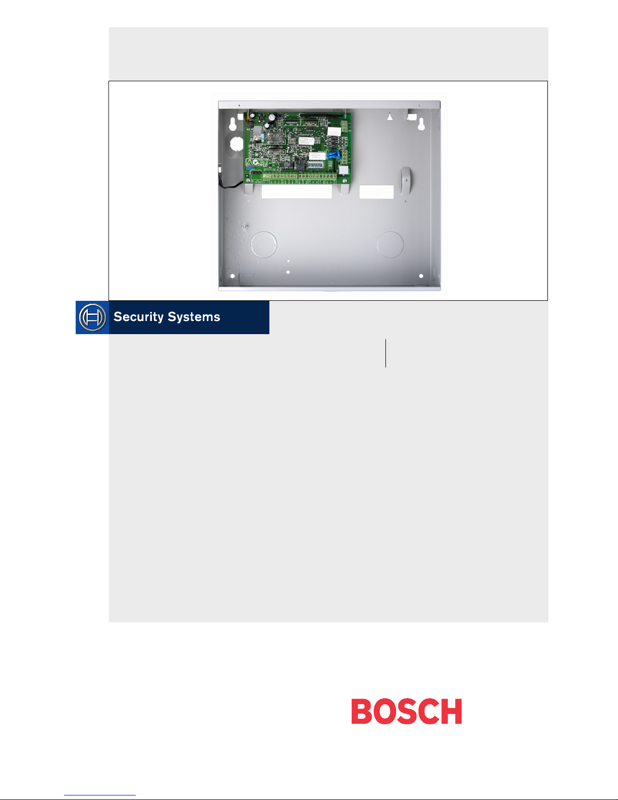
Solution Ultima 880
CC488
Page 2

CC488 | Quick Reference Guide | Notices EN | 2
Bosch Security Systems | 6/04 | 4998152446B
Copyright Notice
Unless otherwise indicated, this publication is the
copyright of Bosch Security Systems Pty Ltd
(“Bosch”). All rights are reserved.
You may download a single copy of this publication.
By downloading the publication you agree that you
will: (i) only use the publication for your own
reference; (ii) not commercially exploit or charge any
person for the use of the publication; and (iii) not
modify the publication in any way without the prior
written permission of Bosch.
Except as specified above or where authorised by the
Copyright Act 1968 (Cth), no part of this publication
may be reproduced, transmitted, modified or stored,
in any form or by any means, without the prior
written permission of Bosch.
Notice of Liability
This material is designed for use by tradespeople with
expertise in the installation of this product. Persons
without appropriate expertise should seek assistance
before attempting installation.
While care has been taken in the preparation of this
material, Bosch Security Systems Pty Ltd and its
representatives will not be responsible to any person
or entity for any loss or damage directly or indirectly
caused by information in, or any omission from, this
material.
Bosch Security Systems Pty Ltd reserves the right to
make changes to features and specifications of its
products at any time without prior notification.
Page 3

CC488 | Quick Reference Guide | Contents EN | 3
Bosch Security Systems | 6/04 | 4998152446B
Contents
1.0 Overview ...........................................................6
1.1 Introduction.......................................................6
1.2 Programming..................................................... 6
1.3 Programming Using A Codepad .................... 6
1.4 Programming Option Bits................................7
1.5 Installer’s Programming Commands.............. 7
1.6 Arming/Disarming the System .......................8
1.7 Isolating Zones ..................................................8
1.7.1 Standard Isolating............................................. 8
1.7.2 Code to Isolate.................................................. 8
1.8 Add/Delete RF Devices (Wireless Zones) .....8
1.8.1 Add RF Device .................................................8
1.8.2 Delete RF Device..............................................8
1.9 Set First Test Report.........................................8
1.10 Event Memory Recall ......................................8
1.11 Walk Test Mode ............................................... 8
1.12 Satellite Siren Service Mode............................9
1.13 Telephone Monitor Mode (Toggle
On/Off).............................................................. 9
1.14 Add/Delete User Code/RF Keyfob................9
1.14.1 Add A User Code.............................................9
1.14.2 Add RF Keyfob................................................. 9
1.14.3 Delete a User Code/RF Keyfob......................9
1.15 Change Domestic Telephone Numbers......... 9
1.16 Turn Outputs On/Off ......................................9
1.17 Setting Date and Time ..................................... 9
1.18 Day Alarm – Toggle On/Off ..........................9
1.19 STAY Mode 2 Zones – Program ....................9
1.20 Fault Analysis ..................................................10
1.21 Modem Call (Alarm Link).............................10
1.22 Latching Outputs (Reset) ...............................10
1.23 Codepad ID/Buzzer Tone .............................10
1.24 Test Report......................................................10
1.25 Speaker Test ....................................................10
1.26 Bell Test ...........................................................10
1.27 Strobe Test (Toggle On/Off)......................... 10
1.28 Telco Arm Sequence (Call Forward On).....10
1.29 Telco Disarm Sequence (Call Forward
Off) ...................................................................10
2.0 Programming Parameters ..............................11
2.1 Phone Programming.......................................11
2.1.1 Phone Number 1 - Receiver 1.......................11
2.1.2 Phone Number 2 - Receiver 1.......................11
2.1.3 Handshake Tone For Receiver 1..................11
2.1.4 Transmission Format For Receiver 1 ...........11
2.1.5 Subscriber ID Number For Receiver 1........11
2.1.6 Phone Number 1 - Receiver 2.......................11
2.1.7 Phone Number 2 - Receiver 2.......................11
2.1.8 Handshake Tone For Receiver 2 ..................11
2.1.9 Transmission Format For Receiver 2 ...........11
2.1.10 Subscriber ID Number For Receiver 2 ........11
2.1.11 Dialling Format ...............................................11
2.1.12 Reserved ..........................................................11
2.1.13 Telco Arming Sequence (Call Forward
On)....................................................................11
2.1.14 Telco Disarm Sequence (Call Forward
Off)....................................................................11
2.1.15 Call Back Telephone Number.......................11
2.1.16 Ring Count ......................................................11
2.1.17 Telephone Line Fail Options.........................12
2.1.18 Dialler Options 1 ............................................12
2.1.19 Dialler Options 2 ............................................12
2.1.20 Dialler Options 3 ............................................12
2.1.21 Dialler Options 3 (V1.04+)............................12
2.1.22 Alarm Link Options .......................................12
2.2 Installer Code..................................................12
2.3 User Code Programming...............................12
2.3.1 User Codes ......................................................12
2.3.2 Authority Levels..............................................12
2.4 Day Alarm Zones............................................13
2.5 EOL Resistor Value........................................13
2.6 Zone Programming.........................................13
2.6.1 Zone Defaults ..................................................13
2.6.2 Zone Types......................................................14
2.6.3 Zone Pulse Count............................................14
2.6.4 Zone Pulse Count Time .................................14
2.6.5 Zone Options 1 ...............................................14
2.6.6 Zone Options 2 ...............................................14
2.6.7 Zone Dialler Options......................................14
2.6.8 Keyswitch Zone Options................................14
2.7 Swinger Programming....................................14
2.7.1 Swinger Shutdown Count For Siren.............14
2.7.2 Swinger Shutdown Count For Dialler ..........14
2.8 Zone Status Programming..............................14
2.8.1 Zone Status – Zone Tamper Report .............14
2.8.2 Zone Status – Walk Test Report ...................14
2.8.3 Zone Status – Bypass Report.........................14
2.8.4 Zone Status – Trouble Report.......................14
2.8.5 Zone Status – Sensor Watch Report.............15
2.8.6 Zone Status – Alarm Restore Code ..............15
2.8.7 Zone Status Reporting Options.....................15
2.9 RF Programming.............................................15
2.9.1 RF Supervision Time......................................15
2.9.2 RF Low Battery Report..................................15
2.9.3 RF Receiver Trouble Report.........................15
2.9.4 RF Receiver Trouble Restore Report...........15
2.9.5 RF Dialler Options .........................................15
2.10 Report Programming......................................15
2.10.1 Open/Close Reports.......................................15
Page 4

CC488 | Quick Reference Guide | Contents EN | 4
Bosch Security Systems | 6/04 | 4998152446B
2.10.2
Open/Close Reporting Options....................15
2.10.3 Codepad Duress Report.................................15
2.10.4 Codepad Panic Report...................................15
2.10.5 Codepad Fire Report......................................15
2.10.6 Codepad Medical Report ..............................15
2.10.7 Codepad Reporting Options......................... 15
2.11 System Status Programming..........................15
2.11.1 System Status – Fuse Fail Report..................15
2.11.2 System Status – Fuse Fail Restore Report....15
2.11.3 System Status – AC Fail Report....................15
2.11.4 System Status – AC Fail Restore Report .....16
2.11.5 System Status – Low Battery Report ............16
2.11.6 System Status – Low Battery Restore
Report ..............................................................16
2.11.7 System Status – Access Denied (Code
Retry)................................................................16
2.11.8 System Status Reporting Options .................16
2.12 Test Report Programming .............................16
2.12.1 Test Report Time (Automatic) ......................16
2.12.2 Test Reporting Dailler Options.....................16
2.13 Output Programming .....................................16
2.13.1 Outputs ............................................................16
2.13.2 Event Codes ....................................................17
2.13.3 Polarity (Modes).............................................. 18
2.13.4 Time Base ........................................................18
2.13.5 Time Base Multiplier......................................18
2.13.6 One Shot Mode ..............................................18
2.13.7 Pulsing Mode...................................................18
2.14 Time Programming ........................................18
2.14.1 Entry Time 1 ...................................................18
2.14.2 Entry Time 2 ...................................................18
2.14.3 Exit Time (AWAY/STAY Modes) ...............18
2.14.4 Entry Guard Time For STAY Mode............18
2.14.5 Delay Alarm Report Time.............................18
2.14.6 Sensor Watch Time ........................................18
2.14.7 Codepad Lockout Time.................................18
2.14.8 Siren Run Time...............................................18
2.14.9 Siren Sound Rate ............................................18
2.14.10 Auto Arming Pre-Alert Time ........................18
2.14.11 Auto Arming Time .........................................18
2.14.12 Auto Disarming Time ....................................18
2.14.13 Kiss-Off Wait Time.........................................18
2.14.14 Speaker Beep Volume....................................19
2.15 Options Programming....................................19
2.15.1 System Options 1............................................19
2.15.2 System Options 2............................................19
2.15.3 System Options 3............................................19
2.15.4 System Options 4............................................19
2.15.5 Consumer Options 1 ......................................19
2.15.6 Consumer Options 2 ......................................19
2.15.7 Consumer Options 3 ......................................19
2.15.8 Radio Input Options.......................................19
2.15.9 Partitioning Options 1 ....................................19
2.15.10 Partitioning Options 2 ....................................19
2.16 Zone Allocations Programming ....................19
2.16.11 Zone Allocations for Area 1 ..........................19
2.16.12 Zone Allocations for Area 2 ..........................19
2.17 User Code Area Assignment.........................20
2.18 Domestic Telephone Numbers .....................20
2.19 Reserved ..........................................................20
2.20 RF Programming.............................................20
2.20.1 RF Options ......................................................20
2.20.2 RF Device Mapping for Devices 1 to 8........20
2.20.3 RF Device Mapping for Devices 9 to 16 .....20
2.20.4 Ring Burst Time (V1.07+) .............................20
2.20.5 RF Signal Strength for Devices 1 to 8 ..........20
2.20.6 RF Signal Strength for Devices 9 to 16 ........20
2.21 System Option Programming........................20
2.21.7 Default Options...............................................20
2.21.2 System Time....................................................20
2.21.3 System Date.....................................................21
3.0 Solution Ultima RF Receiver Interface........22
4.0 RF Keyfob Operations ...................................23
5.0 Connections for Split EOL Resistors............23
5.1 8 Burglary Zones.............................................23
5.2 8 Zone Operation Using N/O Contacts.......24
6.0 Wiring Diagrams.............................................24
6.1 Keyswitch Zone...............................................24
6.2 Solution Ultima Series....................................25
7.0 Component Overlay.......................................26
8.0 Codepad Connections Partitioning...............27
Page 5

CC488 | Quick Reference Guide | Contents EN | 5
Bosch Security Systems | 6/04 | 4998152446B
Figures
Figure 1: RF Receiver (RF 3212/E) Wiring
Diagram.................................................... 22
Figure 2: RF3332/E – 2 Button RF Keyfob..........23
Figure 3: RF3332/E – 4 Button RF Keyfob..........23
Figure 4: Split EOL Wiring Diagram (Location
266 = 15) ..................................................23
Figure 5: Split EOL Wiring Diagram with Tamper
(Location 266 = 14).................................23
Figure 6: Split EOL Wiring Diagrams Using N/O
Contacts.................................................... 24
Figure 7: Wiring Diagram for Keyswitch Zone....24
Figure 8: Solution Ultima Series Wiring
Diagram.................................................... 25
Figure 9: Solution Ultima Series Component
Overlay.....................................................26
Figure 10: Connections for CP-5 Master Partitioned
(CP500P) Codepad and CP-5 Area
Addressable (CP500A) Codepad...........27
Figure 11: Connections for Two CP-5 Eight Zone
Area Addressable (CP500A)
Codepads..................................................27
Tables
Table 1: Quick Guide to Programming..................6
Table 2: Codepad Indicators ...................................7
Table 3: Programming Option Bits.........................7
Table 4: Installer’s Programming Commands .......7
Table 5: Arming/Disarming the System ................8
Table 6: Telephone Monitor Mode ........................9
Table 7: Fault Analysis Conditions .......................10
Table 8: Codepad ID/Buzzer Tone ......................10
Page 6

CC488 | Quick Reference Guide | 1.0 Overview EN | 6
Bosch Security Systems | 6/04 | 4998152446B
1.0 Overview
1.1 Introduction
Thank you for choosing the Solution Ultima 880
Control Panel (model CC488) for your installation.
You will find this system extremely flexible, reliable,
and easy to use. This Quick Reference Guide is supplied
with the system to provide users with enough basic
information to wire, configure, and program the
system. Due to the systems many programmable
features and options, we suggest that you obtain the
CC484/CC486/CC488 Installation Manual that
provides detailed information on system options,
functions, and programming methods.
1.2 Programming
The programming options of the system are stored in
a non-volatile EPROM. This memory holds all
information during a total power loss and can be
changed as many times as required.
The entire programming sequence consists of
entering a location number and changing the data as
required.
Use the following methods to program the system:
• Codepad
• Hand Held Programmer
• Alarm Link Software
1.3 Programming Using A Codepad
The system must be disarmed (with no active alarm)
to program the system. If there is an active alarm or
the system is armed, enter the code for User 1
(Default = 2580) followed by the [#] key. (User Code
1 is factory default as the Master Code.)
To enter Installer’s Programming Mode, enter the
installer code (Default = 1234) followed by the [#]
key. Two beeps are heard and both the STAY and
AWAY indicators flash simultaneously to indicate
that you entered programming mode. The codepad
indicators displays the current data programmed in
LOCATION 000 (first location of the Primary
Telephone Number).
To move to another programming location, enter the
location number followed by the [#] key. The data in
the new location is displayed using the codepad
indicators. (For example, if you enter [3 4 #], the
system jumps to LOCATION 034, the beginning of
the Subscriber ID Number For Receiver 1.)
To move to the next location, press the [#] key. This
steps you to the next location. The data in the next
location is displayed using the codepad indicators.
(For example, if you are currently positioned at
LOCATION 034, pressing the [#] key takes you to
LOCATION 035.)
To step back one location, press the [*] key. (For
example, if you are currently positioned at
LOCATION 35, pressing the [*] key returns to
LOCATION 34.)
To change data in the current location, enter the new
value (0 to 15) followed by the [*] key. This stores the
new data into the location. (For example, if you enter
the value [1 4 *], both the Zone 4 indicator and the
MAINS indicator display to represent the new data
value.)
To move to the next location, press the [#] key. The
data in the next location displays.
To exit Installer’s Programming Mode, enter
[9 6 0 #]. Two beeps are heard and the STAY and
AWAY indicators no longer display. The system
returns to the disarmed state and is ready for use.
Table 1 displays a quick guide to programming:
Table 1: Quick Guide to Programming
Task Keystrokes
Enter Installer’s Programming
Mode
[1 2 3 4 #]
Exit Installer’s Programming
Mode
[9 6 0 #]
Step to next Location [#]
Step back one Location [*]
Program new data into
Location
[Data][*] (Data = 0 to 15)
Jump to another Location [Location No.][#]
Page 7
CC488 | Quick Reference Guide | 1.0 Overview EN | 7
Bosch Security Systems | 6/04 | 4998152446B
Table 2: Codepad Indicators
Data
Value
Zone 1
Indicator
Zone 2
Indicator
Zone 3
Indicator
Zone 4
Indicator
Zone 5
Indicator
Zone 6
Indicator
Zone 7
Indicator
Zone 8
Indicator
MAINS
Indicator
0
1 X
2 X
3 X
4 X
5 X
6 X
7 X
8 X
9 X X
10 X
11 X X
12 X X
13 X X
14 X X
15 X X
1.4 Programming Option Bits
Use option bits to program any combination of the
four different options in one location by adding
the options together. Programming a zero disables
all four options.
Example
If at LOCATION 177 you only want options 1, 2,
and 4, add the numbers together and the total is
the number to be programmed. The number to be
programmed is 7 (1 + 2 + 4 = 7).
Table 3: Programming Option Bits
Option Description
1 Dialler reporting functions allowed
2 Remote arming using telephone allowed
4 Answering machine bypass only when armed
8 Use bell 103 for FSK format
(Disabled = CCITT V21)
1.5 Installer’s Programming
Commands
Installer Programming Commands, displayed in
Table 4, can only be used when you enter
Installer’s Programming Mode. Enter the
command followed by the [#] key.
Table 4: Installer’s Programming Commands
Command Description
958 Enable/disable zone status (hand held programmer
required).
959 Test programming key.
960 Exit Installer’s Programming Mode.
961 Default system back to factory settings.
962 Copy panel memory to programming key.
963 Copy programming key to panel memory.
964 Erase programming key.
965 Default system for domestic dialling format.
966 Enable/disable automatic stepping of locations
when programming.
999 Display software version (hand held programmer
required).
Page 8

CC488 | Quick Reference Guide | 1.0 Overview EN | 8
Bosch Security Systems | 6/04 | 4998152446B
1.6 Arming/Disarming the System
1.7 Isolating Zones
1.7.1 Standard Isolating
1. Press the [*] key twice.
2. Enter the zone number that you want isolated,
followed by the [*] key.
Repeat step 2 if more than one zone is
required to be isolated.
3. Press the [#] key to exit when finished.
1.7.2 Code to Isolate
1. Press the [*] key once.
2. Enter your user code.
3. Enter the zone number that you want isolated,
followed by the [*] key.
Repeat Step 2 if more than one zone is
required to be isolated.
4. Press the [#] key to exit when finished.
1.8 Add/Delete RF Devices (Wireless
Zones)
1.8.1 Add RF Device
1. Enter the four character Installer Code,
followed by [0] and the [#] key (for example,
[1 2 3 4 0 #]).
2. Enter the Device Number (1 to 16) you want
to add, followed by the [#] key.
3. Enter the 9-digit RF device ID number,
followed by the [#] key.
1.8.2 Delete RF Device
1. Enter the Installer Code followed by [0] and
the [#] key (for example, [1 2 3 4 0 #]).
2. Enter the Device Number (1 to 16) you want
to delete, followed by the [#] key.
3. Press the [*] key to delete the RF device.
1.9 Set First Test Report
1. Enter the four character Installer Code,
followed by [1] and the [#] key (for example,
[1 2 3 4 1 #]).
2. Enter the Number Of Days (0 to 15) to wait
until the first test report, followed by the [#]
key.
1.10 Event Memory Recall
Enter the four character Installer Code or Master
Code, followed by [8] and the [#] key (for
example, [1 2 3 4 8 #]).
The last 40 events (non partitioned) or last ten
events (partitioned) are displayed in reverse order
(for example, most recent to least recent).
1.11 Walk Test Mode
1. Enter the four character Installer Code or
Master Code, followed by [7] and the [#] key
(for example, [1 2 3 4 7 #]).
2. Test each zone as required.
3. Press the [#] key to exit.
Table 5: Arming/Disarming the System
AWAY Mode STAY Mode 1 STAY Mode 2
Arming
(On)
Press and hold the [#] key until two
beeps are heard.
Or
Enter your code followed by the [#]
key (for example, [2 5 8 0 #]).
Or
To arm all areas, enter your code
followed by [0] and then the [#] key
(for example, [2 5 8 0 0 #]).
Use a code to arm all areas
simultaneously that the code is
assigned to in AWAY Mode without
needing to arm each area individually.
Press and hold the [*] key until two
beeps are heard.
Or
Enter your code followed by the [*]
key (for example, [2 5 8 0 *]).
Press and hold the [0] key until two
beeps are heard.
Disarming
(Off)
Enter your code followed by the [#]
key (for example, [2 5 8 0 #]).
Or
To disarm all areas, enter your code
followed by [0] and then the [#] key
(for example, [2 5 8 0 0 #]).
Use a code to disarm all areas
simultaneously that the code is
assigned without needing to disarm
each area individually.
Press and hold the [*] key until two
beeps are heard (only if no alarm).
Or
Enter your code followed by the [#]
key (for example, [2 5 8 0 #]).
Press the [0] key until two beeps are
heard (only if no alarm).
Or
Enter your code followed by the [#]
key (for example, [2 5 8 0 #]).
Page 9

CC488 | Quick Reference Guide | 1.0 Overview EN | 9
Bosch Security Systems | 6/04 | 4998152446B
1.12 Satellite Siren Service Mode
Enter the four character Installer Code, followed
by [5] and the [#] key (for example, [1 2 3 4 5 #]).
1.13 Telephone Monitor Mode (Toggle
On/Off)
1. Enter the four character Installer Code,
followed by [6] and the [#] key (for example,
[1 2 3 4 6 #]).
2. Press and hold the [9] key until two beeps are
heard to send a test report.
Table 6: Telephone Monitor Mode
Zone LED Dialling Event
1 Telephone Line Seized
2 Dialling Telephone Number
3 Handshake Received
4 Data Being Sent
5 Kiss-Off Received
None Released Telephone Line
1.14 Add/Delete User Code/RF
Keyfob
1.14.1 Add A User Code
1. Enter the four character Master Code,
followed by [1] and the [#] key (for example,
[2 5 8 0 1 #]).
2. Enter the User Number (1 to 16) you want to
add/change, followed by the [#] key.
3. Enter the new code, followed by the [#] key.
1.14.2 Add RF Keyfob
1. Enter the four character Master Code,
followed by [1] and the [#] key (for example,
[2 5 8 0 1 #]).
2. Enter the User Number (9 to 16) you want to
add, followed by the [#] key.
3. Enter the 9-digit RF keyfob ID number,
followed by the [#] key.
1.14.3 Delete a User Code/RF Keyfob
1. Enter the four character Master Code,
followed by [1] and the [#] key (for example,
[2 5 8 0 1 #]).
2. Enter the User Number (1 to 16) you want to
delete, followed by the [#] key.
3. Press the [*] key to delete the User Code.
1.15 Change Domestic Telephone
Numbers
1. Enter the four character Installer Code or
Master Code, followed by [2] and the [#] key
(for example, [1 2 3 4 2 #]).
2. Enter the digits for the telephone number.
3. If there is more than one telephone number,
press the [*] key, followed by the [4] key
(inserts break between phone numbers) and
repeat Step 2, or press the [#] key to exit.
1.16 Turn Outputs On/Off
1. Enter the four character Master Code,
followed by [5] and the [#] key (for example,
[2 5 8 0 5 #]).
2. Enter the Output Number (1 to 3) you want to
toggle on or off.
3. Press the [#] key to toggle on or the [*] key to
toggle off.
4. Press the [#] key to exit.
1.17 Setting Date and Time
1. Enter the four character Master Code,
followed by [6] and the [#] key (for example,
[2 5 8 0 6 #]).
2. Enter the day (DD), month (MM), and year
(YY) followed by the hour (HH) and minute
(MM).
3. Press the [#] key to exit.
1.18 Day Alarm – Toggle On/Off
Press and hold the [4] key until two beeps are
heard. Day alarm toggles on or off.
1.19 STAY Mode 2 Zones – Program
1. Enter the four character Installer Code or
Master Code, followed by [4] and the [#] key
(for example, [1 2 3 4 4 #]).
2. Enter the Zone Number you want the system
to automatically isolate, followed by the [*]
key.
Repeat if more than one zone must be
automatically isolated when armed in STAY
Mode 2.
3. Press the [#] key to exit.
Page 10

CC488 | Quick Reference Guide | 1.0 Overview EN | 10
Bosch Security Systems | 6/04 | 4998152446B
1.20 Fault Analysis
1. Press and hold the [5] key until two beeps are
heard.
2. Zone Indicators display FAULT conditions
(see Table 7).
3. Press [#] key to exit.
Table 7: Fault Analysis Conditions
Zone
LED
Fault Condition Description
1 System Fault
Press and hold button [1] to
determine fault.
1 = Battery Fail
2 = Date/Time
3 = RF Rx Jamming
RF Rx Tamper
RF Rx Comm’s Fail
4 = Horn Speaker Fail
5 = Telephone Line Fail
6 = E2 Fail
7 = Fuse Fail
8 = AC Fail
2 RF Low Battery Press and hold button [2] to
determine fault.
Displays zones (1 to 8) that register
RF Low Battery.
3 Zone Tamper Press and hold button [3] to
determine fault.
Displays zones (1 to 8) that register
Zone Tamper.
4 Sensor Watch Press and hold button [4] to
determine fault.
Displays zones (1 to 8) that register
Zone Sensor Watch
5 RF Sensor
Watch
Press and hold button [5] to
determine fault.
Displays zones (1 to 8) that register
Zone RF Sensor Watch
6 Communication
Fail
Press and hold button [6] to
determine fault.
1 = Receiver 1 Fail (Dialler)
2 = Receiver 2 Fail (Dialler)
1.21 Modem Call (Alarm Link)
Press and hold the [6] key until two beeps are
heard.
1.22 Latching Outputs (Reset)
Press and hold the [7] key until two beeps are
heard.
1.23 Codepad ID/Buzzer Tone
1. Press and hold the [8] key until the desired
buzzer tone is reached.
If the system is partitioned (CC488 only), the
codepad displays a number identifying which
area the codepad belongs (see Table 8).
2. Press the [#] key to exit.
Table 8: Codepad ID/Buzzer Tone
Zone LED Codepad Assignment
1 Area 1
2 Area 2
7 Master Partitioned Codepad
1.24 Test Report
Press and hold the [9] key until two beeps are
heard.
1.25 Speaker Test
Press and hold the [1] key until two beeps are
heard. The speaker sounds for two seconds.
1.26 Bell Test
Press and hold the [2] key until two beeps are
heard. The piezo sounds for two seconds.
1.27 Strobe Test (Toggle On/Off)
Press and hold the [3] key until three beeps are
heard to turn the strobe on.
Or
Press and hold the [3] key until two beeps are
heard to turn the strobe off.
1.28 Telco Arm Sequence (Call
Forward On)
1. Enter your four character Installer Code or
Master Code followed by [3] and the [#] key
(for example, [1 2 3 4 3 #]).
2. Press [1] followed by the [#] key.
3. Enter the Call Forward On sequence.
4. Press the [#] key to exit.
1.29 Telco Disarm Sequence (Call
Forward Off)
1. Enter your four character Installer Code or
Master Code followed by [3] and the [#] key
(for example, [1 2 3 4 3 #]).
2. Press [2] followed by the [#] key.
3. Enter the Call Forward Off sequence.
4. Press the [#] key to exit.
Page 11

CC488 | Quick Reference Guide | 2.0 Programming Parameters EN | 11
Bosch Security Systems | 6/04 | 4998152446B
2.0 Programming
Parameters
Shaded rows indicate default values.
2.1 Phone Programming
2.1.1 Phone Number 1 - Receiver 1
Location
000 to 015
Default
0
0 = 10 and telephone termination = 0
Anywhere else 0 = 0
2.1.2 Phone Number 2 - Receiver 1
Location
016 to 031
Default
0
0 = 10 and telephone termination = 0
Anywhere else 0 = 0
2.1.3 Handshake Tone For Receiver 1
Location
032
1 HI-LO handshake (contact ID)
2 1400 Hz (Ademco TX @ 1900 Hz)
3 2300 Hz (Sescoa TX @ 1800 Hz)
4 No handshake
5 Pager
2.1.4 Transmission Format For Receiver 1
Location
033
1 Contact ID
2 4 + 2 Expressed
3 FSK 300 Baud
4 Domestic
5 Basic Pager
6 Reserved
7 Reserved
8 4 + 2 Pulsed
2.1.5 Subscriber ID Number For Receiver 1
Location
034 to 039
Default
0
Right justified
2.1.6 Phone Number 1 - Receiver 2
Location
040 to 055
Default
0
0 = 10 and telephone termination = 0
Anywhere else 0 = 0
2.1.7 Phone Number 2 - Receiver 2
Location
056 to 071
Default
0
0 = 10 and telephone termination = 0
Anywhere else 0 = 0
2.1.8 Handshake Tone For Receiver 2
Location
072
1 HI-LO handshake (contact ID)
2 1400 Hz (Ademco TX @ 1900 Hz)
3 2300 Hz (Sescoa TX @ 1800 Hz)
4 No handshake
5 Pager
2.1.9 Transmission Format For Receiver 2
Location
073
1 Contact ID
2 4 + 2 Expressed
3 FSK 300 Baud
4 Domestic
5 Basic Pager
6 Reserved
7 Reserved
8 4 + 2 Pulsed
2.1.10 Subscriber ID Number For Receiver 2
Location
074 to 079
Default
0
Right justified
2.1.11 Dialling Format
Location
080
1 Australian DTMF
2 Australian Decadic
3 Alternate DTMF and Decadic (Aust)
4 International DTMF
5 Reversed Decadic
6 Alternate DTMF and Reversed Decadic
2.1.12 Reserved
Location
081 to 112
2.1.13 Telco Arming Sequence (Call
Forward On)
Location
113 to 142
Default
0
2.1.14 Telco Disarm Sequence (Call
Forward Off)
Location
143 to 158
Default
0
2.1.15 Call Back Telephone Number
Location
159 to 174
Default
0
0 = 10 and telephone termination = 0
Anywhere else 0 = 0
2.1.16 Ring Count
Location
175
Default
8
0 Panel does not answer
1 to 13 No. of rings until panel answers
14 Answering machine bypass 2
15 Answering machine bypass 1
Page 12

CC488 | Quick Reference Guide | 2.0 Programming Parameters EN | 12
Bosch Security Systems | 6/04 | 4998152446B
2.1.17 Telephone Line Fail Options
Location
176
Default
0
1 Display FAULT Indicator when telephone line fails
2 Sound alarm when system is armed
4 Sound alarm when system is disarmed
Options 2 and 4 must be used in conjunction with Option
1 (for example, program 1, 3, 5, or 7)
2.1.18 Dialler Options 1
Location
177
1 Dialler reporting functions allowed
2 Remote arming by telephone allowed
4 Answering machine bypass only when armed
8 Use Bell 103 for FSK format (Disabled = CCITT V21)
2.1.19 Dialler Options 2
Location
178
Default
0
1 Open/Close Reports only if previous alarm
2 Open/Close Reports for STAY Mode 1 and STAY
Mode 2
4 Delay siren until transmission complete
8 Extend handshake wait time from 30 to 55 sec.
2.1.20 Dialler Options 3
Location
179
Default
0
1 Set DTMP dialling pulses to 1 digit/sec.
2 Lockout telephone line fail alarm (V1.03+)
4 Change Decadic dialling to 60/40
8 Reserved
2.1.21 Dialler Options 3 (V1.04+)
Location
179
1 Set DTMP dialling pulses to 1 digit/sec.
2 Lockout telephone line fail alarm (V1.03+)
4 Change Decadic dialling to 60/40
8 External modem module (CC811) required for FSK
(V1.09+)
2.1.22 Alarm Link Options
Location
180
1 Upload/download allowed
2 Call back phone number required for upload/download
4 Exit upload/download connection on alarm
8 External modem module (CC811) required for alarm link
2.2 Installer Code
Location
181 to 184
Location Default
181 1
182 2
183 3
184 4
2.3 User Code Programming
2.3.1 User Codes
Location
185 to 264
Location Default
User #01 185 2
186 5
187 8
188 0
189 (Authority Level) 10
User #02 190 to 193 15
194 2
User #03 195 to 198 15
199 (Authority Level) 2
User #04 200 to 203 15
204 (Authority Level) 2
User #05 205 to 208 15
209 (Authority Level) 2
User #06 210 to 213 15
214 (Authority Level) 2
User #07 215 to 218 15
219 (Authority Level) 2
User #08 220 0
221 to 223 15
224 (Authority Level) 3
RF User #09 225 to 228 15
229 (Authority Level) 2
RF User #10 230 to 233 15
234 (Authority Level) 2
RF User #11 235 to 238 15
239 (Authority Level) 2
RF User #12 240 to 243 15
244 (Authority Level) 2
RF User #13 245 to 248 15
249 (Authority Level) 2
RF User #14 250 to 253 15
254 (Authority Level) 2
RF User #15 255 to 258 15
259 (Authority Level) 2
RF User #16 260 to 263 15
264 (Authority Level) 2
2.3.2 Authority Levels
Authority
Levels
Description
0 Arm/Disarm
1 Arm Only
2 Arm/Disarm and Open/Close Reports
3 Arm Only and Close Reports
4 Arm/Disarm and Code Required to Isolate
6 Arm/Disarm and Open/Close Reports and Code
Required to Isolate
8 Master Code and Arm/Disarm
10 Master Code and Arm/Disarm and Open/Close
Reports
12 Master Code and Arm/Disarm and Code
Required to Isolate
14 Master Code and Arm/Disarm and Code
Required to Isolate and Open/Close Reports
Page 13

CC488 | Quick Reference Guide | 2.0 Programming Parameters EN | 13
Bosch Security Systems | 6/04 | 4998152446B
2.4 Day Alarm Zones
Location
265
Default
0
1 Zone 1
2 Zone 2
4 Zone 3
8 Zone 4
2.5 EOL Resistor Value
Location
266
0 No EOL
1 1k
2 1k5
3 2k2
4 3k3
5 3k9
6 4k7
7 5k6
8 6k8
9 10k
10 12k
11 22k
12 Reserved
13 Reserved
14 Split EOL (3k3/6k8 with tamper 1k)
15 Split EOL (3k3/6k8)
2.6 Zone Programming
2.6.1 Zone Defaults
Location
267 to 322
Location Default
Zone #01 (Default = Delay-1)
Zone Type 267 2
Zone Pulse Count 268 0
Zone Pulse Count Time 269 0
Zone Options 1 270 1
Zone Options 2 271 14
Report Code 272 1
Dialler Options 273 1
Zone #02 (Default = Handover)
Zone Type 274 1
Zone Pulse Count 275 0
Zone Pulse Count Time 276 0
Zone Options 1 277 1
Zone Options 2 278 14
Report Code 279 1
Dialler Options 280 1
Zone #03 (Default = Handover)
Zone Type 281 1
Zone Pulse Count 282 0
Zone Pulse Count Time 283 0
Zone Options 1 284 1
Zone Options 2 285 14
Report Code 286 1
Dialler Options 287 1
2.6.1 Zone Defaults (continued)
Location
267 to 322
Zone #04 (Default = Handover)
Zone Type 288 1
Zone Pulse Count 289 0
Zone Pulse Count Time 290 0
Zone Options 1 291 1
Zone Options 2 292 14
Report Code 293 1
Dialler Options 294 1
Zone #05 (Default = Instant)
Zone Type 295 0
Zone Pulse Count 296 0
Zone Pulse Count Time 297 0
Zone Options 1 298 1
Zone Options 2 299 14
Report Code 300 1
Dialler Options 301 1
Zone #06 (Default = Instant)
Zone Type 302 0
Zone Pulse Count 303 0
Zone Pulse Count Time 304 0
Zone Options 1 305 1
Zone Options 2 306 14
Report Code 307 1
Dialler Options 308 1
Zone #07 (Default = Instant)
Zone Type 309 0
Zone Pulse Count 310 0
Zone Pulse Count Time 311 0
Zone Options 1 312 1
Zone Options 2 313 14
Report Code 314 1
Dialler Options 315 1
Zone #08 (Default = 24 hr. Tamper)
Zone Type 316 9
Zone Pulse Count 317 0
Zone Pulse Count Time 318 0
Zone Options 1 319 1
Zone Options 2 320 12
Report Code 321 1
Dialler Options 322 1
Page 14

CC488 | Quick Reference Guide | 2.0 Programming Parameters EN | 14
Bosch Security Systems | 6/04 | 4998152446B
2.6.2 Zone Types
Zone Type Description
0 Instant
1 Handover
2 Delay-1
3 Delay-2
4 Reserved
5 Reserved
6 24 hr. Medical
7 24 hr. Panic
8 24 hr. Hold-up
9 24 hr. Tamper
10 Reserved
11 Keyswitch
12 24 hr. Burglary
13 24 hr. Fire
14 Chime
15 Not Used
2.6.3 Zone Pulse Count
Use the pulse count to program how many pulses
(0 to 15) need to be registered within the pulse
count time to activate an alarm.
2.6.4 Zone Pulse Count Time
Option 20 ms Loop
Response Time
Option 150 ms Loop
Response Time
0 0.5 sec. 8 20 sec.
1 1 sec. 9 30 sec.
2 2 sec. 10 40 sec.
3 3 sec. 11 50 sec.
4 4 sec. 12 60 sec.
5 5 sec. 13 90 sec.
6 10 sec. 14 120 sec.
7 15 sec. 15 200 sec.
2.6.5 Zone Options 1
Option Description
1 Lockout siren/dialler
2 Delay Alarm report
4 Silent alarm
8 Sensor watch
2.6.6 Zone Options 2
Option Group
1 Isolated in STAY Mode 1
2 Zone isolation allowed
4 Forces arming allowed
8 Zone Restore Report allowed
2.6.7 Zone Dialler Options
Option Description
0 No zone reports allowed
1 Report to Receiver 1
2 Report to Receiver 2
4 Report to both Receiver 1 and Receiver 2
8 Report to Receiver 2 only if Receiver 1 fails
2.6.8 Keyswitch Zone Options
The keyswitch zone options replace Zone Options
1 only for the zones that were programmed to
operate as a keyswitch zone.
Option Description
0 Latching arm and disarm in AWAY Mode
1 Latching arm in AWAY Mode
2 Latching disarm from AWAY Mode or STAY Mode
4 Latching arm and disarm in STAY Mode
5 Latching arm in STAY Mode
6 Latching disarm from STAY Mode
8 Momentary arm and disarm in AWAY Mode
9 Momentary arm in AWAY Mode
10 Momentary disarm from AWAY Mode or STAY
mode
12 Momentary arm and disarm in STAY Mode
13 Momentary arm in STAY Mode
14 Momentary disarm from STAY Mode
2.7 Swinger Programming
2.7.1 Swinger Shutdown Count For Siren
Location
323
Default
3
0 Unlimited
1 to 15 Number of times siren operates until lockout
2.7.2 Swinger Shutdown Count For Dialler
Location
324
Default
6
0 Unlimited
1 to 15 Number of times dialler operates until lockout
2.8 Zone Status Programming
2.8.1 Zone Status – Zone Tamper Report
Location
325 to 326
Location Default
Zone Tamper Report 325 0
Zone Tamper Restore Report 326 0
2.8.2 Zone Status – Walk Test Report
Location
327 to 328
Location Default
Walk Test Start Report 327 0
Walk Test End Report 328 0
2.8.3 Zone Status – Bypass Report
Location
329 to 330
Location Default
Zone Bypass Report 329 9
Zone Bypass Restore Report 330 8
2.8.4 Zone Status – Trouble Report
Location
331 to 332
Location Default
Zone Trouble Report 331 2
Zone Trouble Restore Report 332 3
Page 15

CC488 | Quick Reference Guide | 2.0 Programming Parameters EN | 15
Bosch Security Systems | 6/04 | 4998152446B
2.8.5 Zone Status – Sensor Watch Report
Location
333 to 334
Location Default
Sensor Watch Report 333 4
Sensor Watch Restore Reprot 334 5
2.8.6 Zone Status – Alarm Restore Code
Location
335
Default
14
2.8.7 Zone Status Reporting Options
Location
336
0 No zone status reports allowed
1 Report to Receiver 1
2 Report to Receiver 2
4 Report to both Receiver 1 and Receiver 2
8 Report to Receiver 2 only if Receiver 1 fails
2.9 RF Programming
2.9.1 RF Supervision Time
Location
337
Default
0
Increments of 6 hrs. (0 to 90 hrs.)
2.9.2 RF Low Battery Report
Location
338 to 339
Location Default
RF Low Battery Report 338 6
RF Low Battery Restore Report 339 8
2.9.3 RF Receiver Trouble Report
Location
340 to 341
Location Default
RF Receiver Trouble Report
(tens digit)
340 7
RF Receiver Trouble Report
(units digit)
341 9
2.9.4 RF Receiver Trouble Restore Report
Location
342 to 343
Location Default
RF Receiver Trouble Restore Report
(tens digit)
342 7
RF Receiver Trouble Restore Report
(units digit)
343 11
2.9.5 RF Dialler Options
Location
344
0 No Zone Status Reports allowed
1 Report to Receiver 1
2 Report to Receiver 2
4 Report to both Receiver 1 and Receiver 2
8 Report to Receiver 2 only if Receiver 1 fails
2.10 Report Programming
2.10.1 Open/Close Reports
Location
345 to 346
Location Default
Open Report 345 11
Close Report 346 12
2.10.2 Open/Close Reporting Options
Location
347
0 No Open/Close Reports allowed
1 Report to Receiver 1
2 Report to Receiver 2
4 Report to both Receiver 1 and Receiver 2
8 Report to Receiver 2 only if Receiver 1 fails
2.10.3 Codepad Duress Report
Location
348
Default
6
2.10.4 Codepad Panic Report
Location
349 to 350
Location Default
Tens digit 349 7
Units digit 350 15
2.10.5 Codepad Fire Report
Location
351 to 352
Location Default
Tens digit 351 7
Units digit 352 14
2.10.6 Codepad Medical Report
Location
353 to 354
Location Default
Tens digit 353 7
Units digit 354 13
2.10.7 Codepad Reporting Options
Location
355
0 No Codepad Alarm Reports allowed
1 Report to Receiver 1
2 Report to Receiver 2
4 Report to both Receiver 1 and Receiver 2
8 Report to Receiver 2 only if Receiver 1 fails
2.11 System Status Programming
2.11.1 System Status – Fuse Fail Report
Location
356 to 357
Location Default
Tens digit 356 10
Units digit 357 3
2.11.2 System Status – Fuse Fail Restore
Report
Location
358 to 359
Location Default
Tens digit 358 10
Units digit 359 8
2.11.3 System Status – AC Fail Report
Location
360 to 361
Location Default
Tens digit 360 10
Units digit 361 2
Page 16

CC488 | Quick Reference Guide | 2.0 Programming Parameters EN | 16
Bosch Security Systems | 6/04 | 4998152446B
2.11.4 System Status – AC Fail Restore
Report
Location
362 to 363
Location Default
Tens digit 362 10
Units digit 363 7
2.11.5 System Status – Low Battery Report
Location
364 to 365
Location Default
Tens digit 364 10
Units digit 365 1
2.11.6 System Status – Low Battery Restore
Report
Location
366 to 367
Location Default
Tens digit 366 10
Units digit 367 6
2.11.7 System Status – Access Denied
(Code Retry)
Location
368 to 370
Location Default
Code retry limit (0 = unlimited) 368 6
Tens digit 369 7
Units digit 370 12
2.11.8 System Status Reporting Options
Location
371
0 No Codepad Alarm Reports allowed
1 Report to Receiver 1
2 Report to Receiver 2
4 Report to both Receiver 1 and Receiver 2
8 Report to Receiver 2 only if Receiver 1 fails
2.12 Test Report Programming
2.12.1 Test Report Time (Automatic)
Location
372 to 378
Location Default
Hour of day (tens digit) 372 0
Hour of day (units digit) 373 0
Minute of day (tens digit) 374 0
Minute of day (units digit) 375 0
Test report (tens digit) 376 7
Test report (units digit) 377 1
Repeat interval in days 378 0
2.12.2 Test Reporting Dialler Options
Location
379
0 No Codepad Alarm Reports allowed
1 Report to Receiver 1
2 Report to Receiver 2
4 Report to both Receiver 1 and Receiver 2
8 Report to Receiver 2 only if Receiver 1 fails
2.13 Output Programming
2.13.1 Outputs
Location
380 to 409
Location Default
Output 1 (Default = Horn Speaker)
Event Code 380 1
Event Code 381 14
Polarity 382 0
Time Base 383 0
Time Base Multiplier 384 0
Time Base Multiplier 385 0
Output 2 (Default = Fire Alarm With Verification)
Event Code 386 2
Event Code 387 7
Polarity 388 10
Time Base 389 2
Time Base Multiplier 390 1
Time Base Multiplier 391 5
Strobe Output (Default = Strobe – Reset After 8 hrs.)
Event Code 392 2
Event Code 393 0
Polarity 394 6
Time Base 395 4
Time Base Multiplier 396 0
Time Base Multiplier 397 8
Relay Output (Default = Sirens Running)
Event Code 398 1
Event Code 399 15
Polarity 400 1
Time Base 401 0
Time Base Multiplier 402 0
Time Base Multiplier 403 0
Codepad Buzzer (Default = Entry/Exit Warning and Day
Alarm)
Event Code 404 0
Event Code 405 13
Polarity 406 2
Time Base 407 1
Time Base Multiplier 408 0
Time Base Multiplier 409 1
Page 17

CC488 | Quick Reference Guide | 2.0 Programming Parameters EN | 17
Bosch Security Systems | 6/04 | 4998152446B
2.13.2 Event Codes
Event
Code
Description
0 0 EDMSAT – satellite siren (output 1 only)
0 1 System armed
0 2 System disarmed
0 3 Armed in STAY mode
0 4 Armed in AWAY mode
0 5 Pre-arming alert
0 6 Exit warning (all zones sealed) and entry warning
0 7 Exit warning
0 8 Exit warning finished
0 9 Kiss-off after end of exit time
0 10 Reserved
0 11 Entry warning
0 12 Entry warning and day alarm resetting
0 13 Exit warning and entry warning and day alarm
resetting
0 14 Day alarm resetting
0 15 Day alarm latching
1 0 Day alarm enabled
1 1 Telephone line fail
1 2 Kiss-off received
1 3 Fuse fail
1 4 AC fail
1 5 Low battery
1 6 Horn speaker fail
1 7 Sensor watch alarm
1 8 Codepad medical alarm
1 9 Codepad fire alarm
1 10 Codepad panic alarm
1 11 Codepad duress alarm
1 12 Access denied (code retries)
1 13 Reserved
1 14 Horn speaker (output 1 only)
1 15 Sirens running
2 0 Strobe
2 1 Silent alarm
2 2 Alarm in STAY Mode
2 3 Alarm in AWAY Mode
2 4 System fault
2 5 Fire alarm (resetting)
2 6 Fire alarm (latching)
2 7 Fire alarm (verification)
2 8 Remote control 1
2 9 Remote control 2
2 10 Remote control 3
2 11 Radio control output 1
2 12 Radio control output 2
2 13 Radio control output 1 - not in AWAY Mode
2 14 Radio control output 2 - not in AWAY Mode
2 15 Communications fail after 3 attempts
2.13.2 Event Codes (continued)
Event
Code
Description
3 0 Communications fail
3 1 Dialler disabled
3 2 Dialler active (on-line)
3 3 Ring detect
3 4 Codepad panic (multi-break) V1.05+
3 5 Mimic zone 1
3 6 Mimic zone 2
3 7 Mimic zone 3
3 8 Mimic zone 4
3 9 Mimic zone 5
3 10 Mimic zone 6
3 11 Mimic zone 7
3 12 Mimic zone 8
3 13 Reserved
3 14 Reserved
3 15 Reserved
4 0 Reserved
4 1 Reserved
4 2 Reserved
4 3 Reserved
4 4 Reserved
4 5 Chime
4 6 Zone not sealed
4 7 Zone not sealed after exit time
4 8 Reserved
4 9 AC mains cycle (60 Hz or 50 Hz)
4 10 Area 1 – zone unsealed (Solution 880 only)
4 11 Area 2 – zone unsealed (Solution 880 only)
4 12 Reserved
4 13 Reserved
4 14 Reserved
4 15 Reserved
5 0 Reserved
5 1 Reserved
5 2 Area 1 in alarm (Solution 880 only)
5 3 Area 2 in alarm (Solution 880 only)
5 4 Reserved
5 5 Reserved
5 6 Area 1 armed (Solution 880 only)
5 7 Area 2 armed (Solution 880 only)
5 8 Reserved
5 9 Reserved
5 10 Area 1 disarmed (Solution 880 only)
5 11 Area 2 disarmed (Solution 880 only)
5 12 Reserved
5 13 Reserved
5 14 Any areas armed (Solution 880 only)
5 15 Any areas disarmed (Solution 880 only)
6 0 Area 1 codepad data terminal (Solution 880 only)
6 1 Area 2 codepad data terminal (Solution 880 only)
Page 18

CC488 | Quick Reference Guide | 2.0 Programming Parameters EN | 18
Bosch Security Systems | 6/04 | 4998152446B
2.13.3 Polarity (Modes)
Option Description
0 Disabled
1 Normally open, going low
2 Normally open, pulsing low
3 Normally open, one shot low
4 Normally open, one shot low (reset)
5 Normally open, one shot low (re-trigger)
6 Normally open, latching low
7 Reserved
8 Normally low, going open
9 Normally low, pulsing open
10 Normally low, one shot open
11 Normally low, one shot open (reset)
12 Normally low, one shot open (re-trigger)
13 Normally low, latching open
2.13.4 Time Base
Option Description
1 200 ms
2 1 sec.
3 1 min.
4 1 hr.
2.13.5 Time Base Multiplier
Enter a value between 01 and 99.
2.13.6 One Shot Mode
When you program the output polarity as one
shot, the time base is multiplied by the time base
multiplier. (For example, if the time base = 2 and
the multiplier = 05, the output operates for 10 sec.)
2.13.7 Pulsing Mode
When you program the output polarity as pulsing,
the time base becomes the ON time and the
multiplier becomes the OFF time. The OFF time is
the time base x the multiplier. (For example, if you
want the output to pulse 1 sec. ON and 5 sec.
OFF, you would program time base as one and the
multiplier as five.)
2.14 Time Programming
2.14.1 Entry Time 1
Location
410 to 411
Location Default
Increments of 1 sec. (0 to 15 sec.) 410 4
Increments of 16 sec. (0 to 240 sec.) 411 1
2.14.2 Entry Time 2
Location
412 to 413
Location Default
Increments of 1 sec. (0 to 15 sec.) 412 8
Increments of 16 sec. (0 to 240 sec.) 413 2
2.14.3 Exit Time (AWAY/STAY Modes)
Location
414 to 415
Location Default
Increments of 1 sec. (0 to 15 sec.) 414 12
Increments of 16 sec. (0 to 240 sec.) 415 3
2.14.4 Entry Guard Time For STAY Mode
Location
416 to 417
Location Default
Increments of 1 sec. (0 to 15 sec.) 416 0
Increments of 16 sec. (0 to 240 sec.) 417 0
2.14.5 Delay Alarm Report Time
Location
418 to 419
Location Default
Increments of 1 sec. (0 to 15 sec.) 418 0
Increments of 16 sec. (0 to 240 sec.) 419 0
2.14.6 Sensor Watch Time
Location
420 to 421
Location Default
Increments of days (tens digit) 420 0
Increments of days (units digit) 421 0
2.14.7 Codepad Lockout Time
Location
422
Default
0
Increments of 10 sec. (0 sec. to 150 sec.)
2.14.8 Siren Run Time
Location
423
Default
5
Increments of 1 min. (0 min. to 15 min.)
2.14.9 Siren Sound Rate
Location
424
Default
7
0 = Slowest frequency
15 = Fastest frequency
2.14.10 Auto Arming Pre-Alert Time
Location
425
Default
1
Increments of 5 min. (0 min. to 75 min.)
2.14.11 Auto Arming Time
Location
426 to 429
Location Default
Hour of the day (tens digit) 426 0
Hour of the day (units digit) 427 0
Minute of the day (tens digit) 428 0
Minute of the day (units digit) 429 0
2.14.12 Auto Disarming Time
Location
430 to 433
Location Default
Hour of the day (tens digit) 430 0
Hour of the day (units digit) 431 0
Minute of the day (tens digit) 432 0
Minute of the day (units digit) 433 0
2.14.13 Kiss-Off Wait Time
Location
434
Default
3
Increments of 500 ms (500 ms = 8 sec.)
Page 19

CC488 | Quick Reference Guide | 2.0 Programming Parameters EN | 19
Bosch Security Systems | 6/04 | 4998152446B
2.14.14 Speaker Beep Volume
Location
435
Default
13
0
15
No Beeps
Loudest Beeps
2.15 Options Programming
2.15.1 System Options 1
Location
436
1 Bosch Security Systems smart lockout allowed
2 Horn speaker monitor
4 Strobe indication for radio arm/disarm
8 Assign button 4 on transmitter to operate STAY Mode 1
2.15.2 System Options 2
Location
437
Default
0
1 Codepad panic to be silent
2 Codepad fire to be silent
4 Codepad medical to be silent
8 Access denied (code retries) to be silent
2.15.3 System Options 3
Location
438
1 AC fail after 1 hr. (Disabled = after 2 min.)
2 Ignore AC fail
4 Pulse count handover allowed
8 Handover delay to be sequential
2.15.4 System Options 4
Location
439
Default
0
1 Panel to power up disarmed (if power reset)
2 Arm/disarm tracking on power up
4 Internal crystal to keep time
8 Radio keyswitch interface, night arm station, or RE005
installed
2.15.5 Consumer Options 1
Location
440
Default
0
1 Test reports only when armed
2 Test report after siren reset
4 Auto arm in STAY Mode 1
8 STAY indicator to display day alarm status
2.15.6 Consumer Options 2
Location
441
1 Codepad displays extinguish after 60 sec.
2 Single button arming allowed (AWAY/STAY Modes 1 and
2)
4 Single button disarming allowed (STAY Modes 1 and 2)
8 Alarm memory reset on disarm
2.15.7 Consumer Options 3
Location
442
1 Codepad fault beeps allowed
2 Use digit 3 for codepad duress alarm (instead of digit 9)
4 Alarms activate sirens and strobe outputs in STAY
Modes 1 and 2
8 Zone tamper alarms to be silent
2.15.8 Radio Input Options
Location
443
Default
0
1 RF Receiver (RF-3212/E) connected
2 Latching keyswitch input
3 Momentary keyswitch input
4 Reserved
2.15.9 Partitioning Options 1
Location
444
Default
0
1 First to Open/Last to Close reporting armed
2 Area 1 codepad connected to data terminal
4 Reset sirens from any area allowed
8 Master codepad to display AUX indicator when online
2.15.10 Partitioning Options 2
Location
445
Default
0
1 Lock area 1 to Receiver 1 and lock area 2 to Receiver 2
2 User codes allowed to arm/disarm both areas at same time
(Code [0][#])
4 Reserved
8 Reserved
2.16 Zone Allocations Programming
2.16.1 Zone Allocations for Area 1
Location
446 to 453
Location Default
Zone 1 LED – Area 1 Codepad 446 0
Zone 2 LED – Area 1 Codepad 447 0
Zone 3 LED – Area 1 Codepad 448 0
Zone 4 LED – Area 1 Codepad 449 0
Zone 5 LED – Area 1 Codepad 450 0
Zone 6 LED – Area 1 Codepad 451 0
Zone 7 LED – Area 1 Codepad 452 0
Zone 8 LED – Area 1 Codepad 453 0
2.16.2 Zone Allocations for Area 2
Location
454 to 461
Location Default
Zone 1 LED – Area 2 Codepad 454 0
Zone 2 LED – Area 2 Codepad 455 0
Zone 3 LED – Area 2 Codepad 456 0
Zone 4 LED – Area 2 Codepad 457 0
Zone 5 LED – Area 2 Codepad 458 0
Zone 6 LED – Area 2 Codepad 459 0
Zone 7 LED – Area 2 Codepad 460 0
Zone 8 LED – Area 2 Codepad 461 0
Page 20

CC488 | Quick Reference Guide | 2.0 Programming Parameters EN | 20
Bosch Security Systems | 6/04 | 4998152446B
2.17 User Code Area Assignment
Location
462 to 477
Location Default
User Code 1 462 0
User Code 2 463 0
User Code 3 464 0
User Code 4 465 0
User Code 5 466 0
User Code 6 467 0
User Code 7 468 0
User Code 8 469 0
User Code 9 470 0
User Code 10 471 0
User Code 11 472 0
User Code 12 473 0
User Code 13 474 0
User Code 14 475 0
User Code 15 476 0
User Code 16 477 0
0 User code not assigned
1 User code assigned to Area 1
2 User code assigned to Area 2
3 User code assigned to both Area 1 and Area 2
2.18 Domestic Telephone Numbers
Location
478 to 525
2.19 Reserved
Location
526
Default
0
2.20 RF Programming
2.20.1 RF Options
Location
527
Default
0
1 Sound siren on RF Receiver fail
2 Sound siren on RF Receiver tamper/jamming
4 Unseal zone that fails supervision (if supervision enabled)
8 RF jamming monitoring allowed
2.20.2 RF Device Mapping for Devices 1 to 8
Location
528 to 535
Location Default
Map RF Device 1 to Zone (1 to 8) 528 1
Map RF Device 2 to Zone (1 to 8) 529 2
Map RF Device 3 to Zone (1 to 8) 530 3
Map RF Device 4 to Zone (1 to 8) 531 4
Map RF Device 5 to Zone (1 to 8) 532 5
Map RF Device 6 to Zone (1 to 8) 533 6
Map RF Device 7 to Zone (1 to 8) 534 7
Map RF Device 8 to Zone (1 to 8) 535 8
2.20.3 RF Device Mapping for Devices 9 to
16
Location
536 to 543
Location Default
Map RF Device 9 to Zone (1 to 8) 536 0
Map RF Device 10 to Zone (1 to 8) 537 0
Map RF Device 11 to Zone (1 to 8) 538 0
Map RF Device 12 to Zone (1 to 8) 539 0
Map RF Device 13 to Zone (1 to 8) 540 0
Map RF Device 14 to Zone (1 to 8) 541 0
Map RF Device 15 to Zone (1 to 8) 542 0
Map RF Device 16 to Zone (1 to 8) 543 0
2.20.4 Ring Burst Time (V1.07+)
Location
748 to 749
Location Default
Increments of 5 ms. (0 to 75 ms) 748 4
Increments of 80 ms. (0 to 1200 ms) 749 6
2.20.5 RF Signal Strength for Devices 1 to 8
Location
801 to 808
Location Default
Signal Strength for RF Device 1 801 0
Signal Strength for RF Device 2 802 0
Signal Strength for RF Device 3 803 0
Signal Strength for RF Device 4 804 0
Signal Strength for RF Device 5 805 0
Signal Strength for RF Device 6 806 0
Signal Strength for RF Device 7 807 0
Signal Strength for RF Device 8 808 0
2.20.6 RF Signal Strength for Devices 9 to
16
Location
809 to 816
Location Default
Signal Strength for RF Device 9 809 0
Signal Strength for RF Device 10 810 0
Signal Strength for RF Device 11 811 0
Signal Strength for RF Device 12 812 0
Signal Strength for RF Device 13 813 0
Signal Strength for RF Device 14 814 0
Signal Strength for RF Device 15 815 0
Signal Strength for RF Device 16 816 0
2.21 System Option Programming
2.21.1 Default Options
Location
900
0 Defaulting System Allowed
15 Defaulting System Disabled
2.21.2 System Time
Location
901 to 904
Location Default
Hour of the day (tens digit) 901 0
Hour of the day (units digit) 902 0
Minute of the day (tens digit) 903 0
Minute of the day (units digit) 904 0
Page 21

CC488 | Quick Reference Guide | 2.0 Programming Parameters EN | 21
Bosch Security Systems | 6/04 | 4998152446B
2.21.3 System Date
Location
905 to 910
Location Default
Day of the month (tens digit) 905 0
Day of the month (units digit) 906 1
Month of the year (tens digit) 907 0
Month of the year (units digit) 908 1
Current year (tens digit) 909 0
Current year (units digit) 910 1
Page 22

CC488 | Quick Reference Guide | 3.0 Solution Ultima RF Receiver Interface EN | 22
Bosch Security Systems | 6/04 | 4998152446B
3.0 Solution Ultima RF Receiver Interface
Figure 1: RF Receiver (RF 3212/E) Wiring Diagram
1 2
1 = Solution Ultima Control Panel
2 = RF Receiver (RF 3212/E)
Wiring and Power Up:
1. Remove power from the control panel.
2. Connect the RF Receiver to the control panel as shown above using 0.8 mm (22 AWG) or larger wire.
Wire length should not exceed 300 m (1000 feet).
3. Apply power to the control panel. The red LED at the centre of the module turns on.
Operation:
The following describes the status of the module based on the LED condition.
• LED On – Module is functioning normally.
• LED Off – Power failure has occurred or module is not wired correctly.
• LED Turns Off Momentarily – Module acknowledged receiving an RF signal from a remote RF device.
Page 23

CC488 | Quick Reference Guide | 4.0 RF Keyfob Operations EN | 23
Bosch Security Systems | 6/04 | 4998152446B
4.0 RF Keyfob Operations
Figure 2: RF3332/E – 2 Button RF Keyfob
1
2
3
1 = Button 1: Arm in AWAY Mode
2 = Button 2: Disarm from AWAY/STAY Mode
3 = Buttons 1 and 2: Press both buttons
simultaneously to activate Panic alarm.
Figure 3: RF3332/E – 4 Button RF Keyfob
3
21
4
5
1 = Button 4: Arm in STAY Mode 1
2 = Button 3: Optional
3 = Button 1: Arm in AWAY Mode
4 = Button 2: Disarm from AWAY/STAY Mode
5 = Buttons 1 and 2: Press both buttons
simultaneously to activate Panic alarm.
5.0 Connections for Split
EOL Resistors
5.1 8 Burglary Zones
Figure 4: Split EOL Wiring Diagram
(Location 266 = 15)
1
9
2 9
4
9
3
9
5
10
8
10
6 10
7
10
1 = Zone 1
2 = Zone 2
3 = Zone 3
4 = Zone 4
5 = Zone 5
6 = Zone 6
7 = Zone 7
8 = Zone 8
9 = 3k3
10 = 6k8
Figure 5: Split EOL Wiring Diagram with Tamper
(Location 266 = 14)
1 2
3
3
4
5
1 = Zone 1
2 = Zone 5
3 = Tamper
4 = +12 V
5 = Zone 1
Page 24

CC488 | Quick Reference Guide | 6.0 Wiring Diagrams EN | 24
Bosch Security Systems | 6/04 | 4998152446B
5.2 8 Zone Operation Using N/O Contacts
Figure 6: Split EOL Wiring Diagrams Using N/O Contacts
2
2
1
3
3
1
4
5
4
6
4
7
4
8
99
4
5
4
6
8
9
10
1 = +12 V
2 = Zone Input
3 = Zone
4 = EOL
5 = 3k3
6 = 6k8
7 = 1k5
8 = 4k7
9 = N/O
10 = N/C
6.0 Wiring Diagrams
6.1 Keyswitch Zone
Figure 7: Wiring Diagram for Keyswitch Zone
1 2
1 = EOL
2 = Keyswitch (Momentary/Toggle)
Page 25

CC488 | Quick Reference Guide | 6.0 Wiring Diagrams EN | 25
Bosch Security Systems | 6/04 | 4998152446B
6.2 Solution Ultima Series
Figure 8: Solution Ultima Series Wiring Diagram
1
2
3
4
7
5
9
6
8
14
15
10
11
12
13
10
10
11
1 = 605 Plug
2 = 1 (Green) - Internal phone line
5 (Yellow) - Internal phone line
2 (Black) - Telecom line (street)
6 (Red) - Telecom line (street)
3 and 4 - Not used
3 = Power to external equipment: 12V @ 400 Ma
4 = PIR
5 = Piezo siren
6 = Smoke detector
7 = Link between +12 V and Comm
8 = Strobe
9 = Horn speaker
10 = Yellow
11 = Green
12 = Red
13 = Black
14 = Codepad
15 = 18 VAC 1.3 A Plug Pack (TF008)
Page 26

CC488 | Quick Reference Guide | 7.0 Component Overlay EN | 26
Bosch Security Systems | 6/04 | 4998152446B
7.0 Component Overlay
Figure 9: Solution Ultima Series Component Overlay
1 2
3
4
5
6
9
8
14
15
11
12
13
7
10
1 = OUT – Internal phone line
OUT – Internal phone line
IN – Telecom line (street)
IN – Telecom line (street)
2 = Termination for phone line
3 = Socket for telecom lead connection
4 = Receiver interface connection
5 = Zone termination strip
6 = Phone amplifier or direct link cable
7 = Relay contact select
8 = Programming key or hand help programmer plugs
9 = Output termination strip
10 = Default switch
11 = 3 A battery fuse
12 = 1 A accessory fuse
13 = 1 A codepad fuse
14 = Battery input
15 = Plug pack input (Bosch Security Systems TF008)
Page 27

CC488 | Quick Reference Guide | 8.0 Codepad Connections Partitioning EN | 27
Bosch Security Systems | 6/04 | 4998152446B
8.0 Codepad Connections
Partitioning
Figure 10: Connections for CP-5 Master
Partitioned (CP500P) Codepad and
CP-5 Area Addressable (CP500A)
Codepad
1
1
2
3
4
5 6
1 = Data
2 = CLK
3 = +12 V
4 = GND
5 = Master Partitioned Codepad
6 = Addressable Area Codepad
If the CP-5 Area Addressable (CP500A) codepad
is assigned to Area 1, DIP Switch 1 on the back of
the remote codepad must be in the ON position.
The following locations for Output 1 must be
programmed.
[LOCATION 380 = 6, 381 = 0]
If the CP-5 Area Addressable (CP500A) codepad
is assigned to Area 2, DIP Switch 2 on the back of
the remote codepad must be in the ON position.
The following locations for Output 1 must be
programmed.
[LOCATION 380 = 6, 381 = 1]
Note:
The Master Partitioned Keypad requires setting all
DIP switches to the ON position to operate correctly.
Figure 11: Connections for Two CP-5 Eight Zone
Area Addressable (CP500A)
Codepads
1
1
2
3
4
5 6
1 = Data
2 = CLK
3 = +12 V
4 = GND
5 = Area 1 Codepad
6 = Area 2 Codepad
The following DIP Switch settings and locations
must be programmed for the two CP-5 Area
Addressable (CP500A) codepads to function
correctly.
AREA 1 CODEPAD
DIP Switch 1 on the back of the remote codepad
must be in the ON position. The following
location must be programmed.
[LOCATION 444, Option bit 2 must be enabled]
AREA 2 CODEPAD - (Output 1)
DIP Switch 2 on the back of the remote codepad
must be in the ON position. The following
locations for Output 1 must be programmed.
[LOCATION 380 = 6, 381 = 1]
Page 28

© 2004 Bosch Security Systems
4998152446B
05-SUB-MA88Q-3323
Issue 1.73
Bosch Security Systems
25 Huntingwood Drive
Huntingwood NSW 2148
Australia
Phone: +612 9672 1777
Facsimile: +612 9672 1717
 Loading...