

Page 1
ce
120M
Operating Instructions
4 5
--
I
Version 102
BOSCH
Automation
Page 2

Page 3
ce
120M
Operating Instructions
1070 073 435-102 (92.03)
GB
All rights reserved, including applications tor protective rights.
Reproduction
Reg.
Nr.
16149-03
©
1991
by Robert Bosch GmbH,
or
handing overto third parties are subject to our written permission.
Discretionary charge
20.-
DM
Page 4

Page 5
@ BaSCH
Flexible Automation
Table of contents
Table
of
contents
ce
120 M
Operating Instroctions
New ehapters. whieh did not appearinCC
General 1-1
Prelaee
Abbreviations . . . . . . . . . . . . . . . . . . . . . . . . . . . . . . . . . . . . . . . . . . . . . . . . . . . . . . . . . . . . . . . . . . . . . ...1-2
Control panel . . . . . . . . . . . . . . . . . . . . . . . . . . . . . . . . . . . . . . . . . . . . . . . . . . . . . . . . . . . . . . . . . . . . .
Contral elements01the
Manual panel . . . . . . . . . . . . . . . . . . . . . . . . . . . . . . . . . . . . . . . . . . . . . . . . . . . . . . . . . . . . . . . . . . . . . ...1-6
Control elements01the
Sereen layoutin"GOM MACHINE"
Operating instruetions ,
Symbols used
Initial display 2-1
Memory general
Part programsorcyeles
Editing. inputting and outputting part programs
Editing a program line
Deleting a program line
Searehing
Example: Searehing
Example: Inserting a !ine . . . . . . . . . . . . . . . . . . . . . . . . . . . . . . . . . . . . . . . . . . . . . . . . . . . . . . . . ...2-8
Renaming a program
Deleting a program
PROTECTION
Units01measurement (ineh/metrie) , 2-11
Notes
Copying a program ,
Converting programs to eyeles . . . . . . . . . . . . . . . . . . . . . . . . . . . . . . . . . . . . . . . . . . . . . . . . . . . . . ...2-13
Renumbering programs
CYCLES
Drilling and eontour eyeles
Example01drilling eyeles
Contour eyeles
Tables 2-21
Editing
Zero shiltlvariables table "
Variables
Input/output
Example: inputting
Example: outputting programs/eyeles/tables
Formatleheeksum
1.
2. Inputting/outputting the eheeksum
for
eharaeter strings/inserting a text
ON/OFF
on
units01measurement , 2-11
the
tool table : 2-21
functions
DFS
program header
panel.
manual panel... . . . . . . . . . . . . . . . . . . . . . . . . . . . . . . . . . . . . . . . . . . . . . ...1-7
lor
an
. . . . . . . . . . . . . . . . . . . . . . . . . . . . . . . . . . . . . . . . . . . . . . . . . . . . . . ...1-4
program end/M30
individual part program
100
'"
Mare
marked with a
"0"
belore the page number.
2-16.
0
...
1-2
1-3
1-9
1-10
1-10
2-2
2-3
2-3
2-5
2-6
2-6
2-7
2-9
2-10
2-10
2-12
2-14
2-15
2-17
2-18
2-20
2-24
2-24
2-25
2-26
2-27
2-28
2-28
2-29
Cont. - 1
Page 6
@ BOSCH
Flexible Automation
Table of contents
ce
120 M
Operating Instructions
Initial display
Basic funetions 3-1
Approaehing
Manual
Exampie: traversing axes manually
Example: entering a block . . . . . . . . . . . . . . . . . . . . . . . . . . . . . . . . . . . . . . . . . . . . . . . . . . . . . . . ...3-6
Teach
Seleeling
Initial display
Basic funetions 4
Automatic
Procedure
Automatie exeeutioninnormal
Seleeting/editing the step size
Aetivating a stop point
Seleeting an
Seleeting the milling eonditions
Calling
Seleeting the start point
Departure/re-entry during automatie
Proeedure
Procedure
Tables 4-11
DRIP
SeleC1ing
Simulation
in
CPC
FEEDING
..........................................•.............................
referenee
mode
the
unitofmeasurement
executionofprograms/cycles
before
NC
block direetly/defining braneh destinations
test
after
NC Start
(automatic
drip feeding
points(s)
NC Start
"
inch/metrie
mode/dry
.................................................•.......
mode
via
run/rapid leed
mode
interface)
3-1
3-2
3-3
3-3
3-7
3-12
4.,.'
4-"
4-2
4-3
4-4
4-5
4-6
4-6
4-8
4-8
4-8
4-9
4-10
4-12
4-12
4-14
Initial display 5-1
Options . . . . . . . . . . . . . . . . . . . . . . . . . . . . . . . . . . . . . . . . . . . . . . . . . . . . . . . . . . . . . . . . . . . . . . . . . . . . . 5-1
Machine
Meaningofmachine
NC
Errors and mesaages
Axis displays
Status table . . . . . . . . . . . . . . . . . . . . . . . . . . . . . . . . . . . . . . . . . . . . . . . . . . . . . . . . . . . . . . . . . . . . . . . . .
PIC/PC displays
Calling up search functians 5-11
Seleeting
I/Ollag8
Calling up trigger functians
Service
Logbook
status
110
status
Meaning
time/counter
lunctions
functions
ofaxis
.....
. . . . . . . . . . . . . . . . . . . . . . . . . . . . . . . . . . . . . . . . . . . . . . . . . . . . . . . .
status
display functians : .
functions
tables and
110
f1ags
"
Cant. - 2
'"
5-2
5-4
5-5
5-6
5-7
5-7
5-8
5-10
5-12
5-13
5-14
5-'
5-1
i
Page 7
@ BOSCH
Flexible
Automation
Table of contents
Operating
ce
120 M
Instructions
Displaying logbook
Outputting logbook . . . . . . . . . . . . . . . . . . . . . . . . . . . . . . . . . . . . . . • . . . . . . . . . . . . . . . . . . . . . .•.5-18
Setting the clock and date display
Selecting the language
Selecting
Interface
DRIP
Buffer size
Block offset
DNC
MTB
Softkey architecture
Reset and delete
Control reset
ON
UNE
.......•.........................•.......................•.•...•.......•...
FEEDING
..............................................•.........................•
..•.•.................................................................•
INTERFACE
service/resetldelete
......................................•........................
........................•...•.....................
............•............................................•.
PIC/ON
with
UNE
PANEL/ON
LSV 2
for
protocol
......................................•......................
machine tool builder
UNE
DNC
..........................•.......................
......•..............•.....................•
....................................•.
Q
5-17
5-19
5-19
5-20
5-20
5-21
5-22
5-22
5-24
5-24
5-25
5-25
5-25
Cont. - 3
Page 8

Page 9

Page 10

Page 11
~
BOSCH
Flexible Automation
General
1 Introduction
ce 120 M
ce 120 M
Operating Instructions
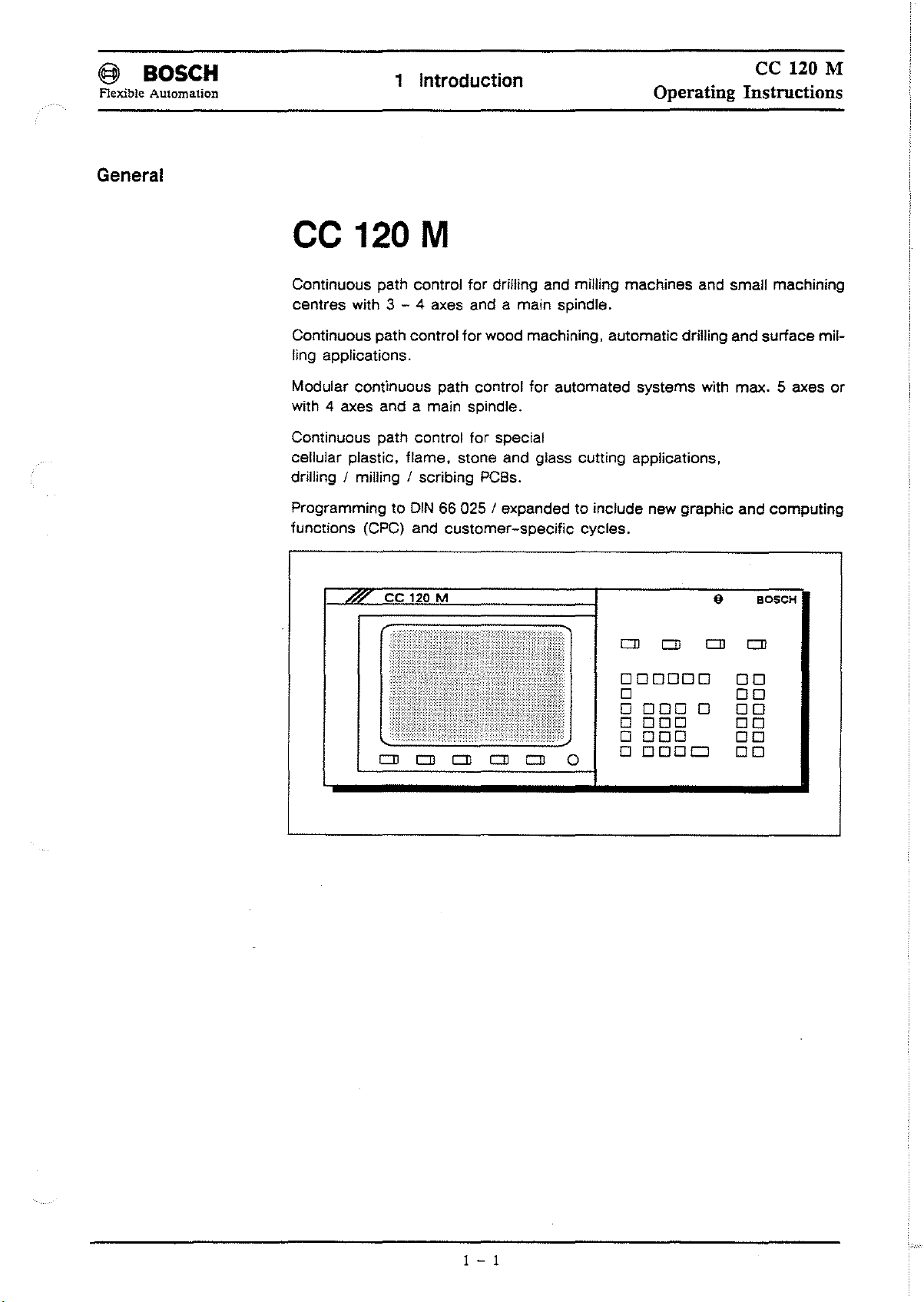
Continuous path controi
centres with 3 - 4 axes and a main spindie.
Continuous path control
Iing applications.
Modular continuous path control
with 4 axes and a main spindie.
Continuous path contral
cellular plastic. flame. stone and glass cutting applications,
drilling / milling / scribing PCBs.
Programming to
functions (CPC) and
ce
CD
DIN
120 M
CD CD
for
driiling and milling machines and small machining
for
wood machining. automatie drilling and surface mil-
for
automated systems with max. 5 axes
for
special
66 025 / expandedtoinclude new graphie and computing
customer-specific
CD
CD
cycles.
0
CD
000000
0
00000
0000
0000
00000
CD
CD
or
{I
BOSCH
CD
00
00
00
00
00
00
1 - 1
Page 12
(@
BOSCH
Flexible Automation
Preface
1 Introduction
The operating instructions only apply to software versions.2
Operating Instructions
850.
ce
120 M
The control unit features 4 group operating
the
ted with
page
1-3).
MEMORY
MACHINE
symbolsinthe upper right hand
[2]
Chapter 2
Chapter
3
modes
corner
~
AUTOMATIC
(execution of
prograrn)
INFO
These
examples.
In
GOMs
the "INTRODUCTION" chapter
[2]
@]
will be describedinthe following chapters, and iIIustrated with
o the control panel,
o the control elements
o
the
manual panel,
o the control elements of the manual panel and
o the screen layout
theCC120 M
of
the symbols used explained.
Please refer
terms.
will
to
the specialised index at the endofthe
Chapter
Chapter
of
be briefly outJined, instructions on use willbeprovided and
4
5
the panel,
(GOM).which can be selec-
of the control panel (see
manual
for
individual
Abbreviations
BAUD
CNC
OCR Digital Cassette Recorder
DFS
DNC
110
GOM
Kbyte
LSV
MP
Transmission rate (baud rate)inbits/sec
Computerized Numerical Contral
Define Store Program
Direct Numerical Control
InputlOutput
Group Operating Mode
1024
bytes
Proceduretosecure cables
Machine Parameters
Ne NumericaJ Control
P Part program
Pie
RAM
SK
F Feed
MTB
Programmable Interface Controller
Random
Softkey
Machine T
Access Memory
001
Builder
1 - 2
Page 13
(§
BOSeH
Flexible
Automation
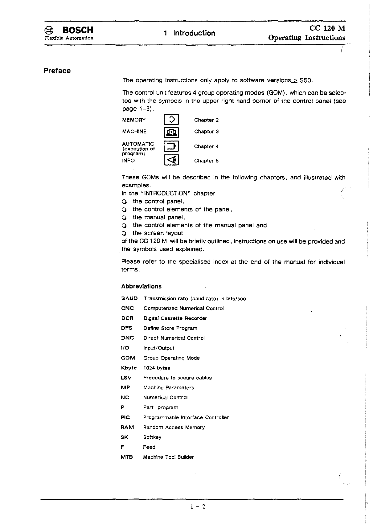
Control panel
Service
Automatie
Dlrect
machine
1 Introduction
Information
executlonofprograms
mode
ce
120 M
Operating Instructions
Bracketed tunetions
(secondary functlon)
Delete key
I
<:a
I-------------+--~
I:JI
I
[[t]
l------~
~
Memory mode
[2]
Softkeys
Meanlng varies depending on
operating mode and status.
There are several softkey levels
which can be selected consecutively,
Page
back
key ®
"R"
can be used
preselect
the
to
previous
softkey
level.
Axis addresses and
computing functions
CPC:
enter
upper function
Computing
Additional and auxiliary functions
and
root
functions
Digits I branches
ICPC
test
1 - 3
ENTER
key
Additional
tunetions )
Space key
SHIFT: enter
upper functlon
characters
Page 14
@ BaSeH
Flexible Automation
1 Introduction
ce
120 M
Operating Instructions
Control elements
of
the panel
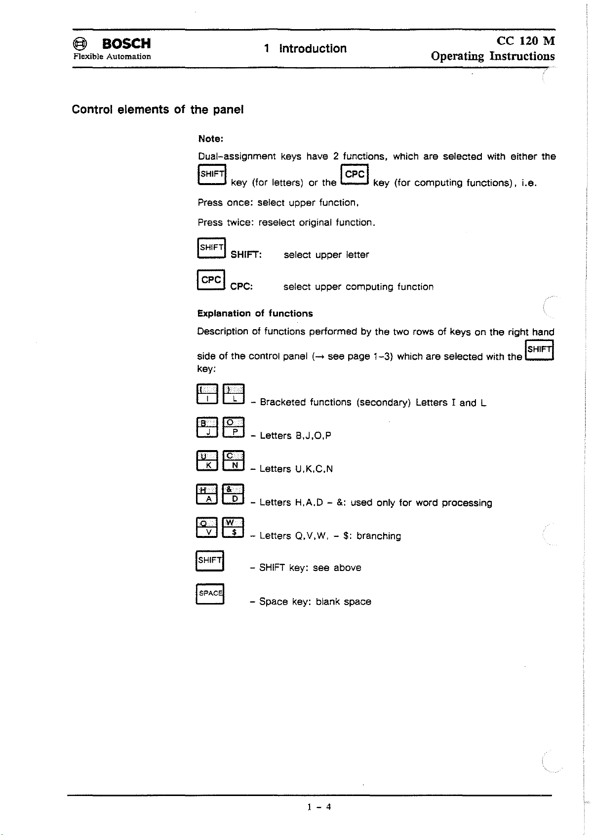
Note:
Dual-assignmenl
ISH'FTI
Press
Press
ISH'FTI
I
CPcl
Explanation
Deseriplionoffunelions
sideofIhe
key:
key
(for leiters)orIhe
onee:
Iwiee:
SHIFT:
CPC:
conlral
keys have 2 funelions. whieh
ICPCI
seleel
reselecl
of
upper
original funetion.
seleel
selecl
functions
panel
funelion.
upper
upper
performedbyIhe
(-+
leller
compuling
see
page
are
selecled
key
(for
eompuling
funelion
IwO rowsofkeysonIhe
1-3)
which are
selecled
with
funclions).
with
eilher
Le.
righl
the
Ihe
hand
~
c:::.J
eTI~
EZlEtJ
IUKIIC~1
~~
~~
- Bracketed funclions (secondary)
- Leiters B,J,O,P
_
Leiters
-
Leiters
-
Leiters
SHIFT
-
- Space key: blank spaee
U.K,C,N
H.A,D-&:
Q.
v.
W, -
key:
see
used only
$:
above
branching
for
Leiters
word
land
L
processing
1 - 4
Page 15
@ BOSCH
Flexible Automation
ce
1 Introduction
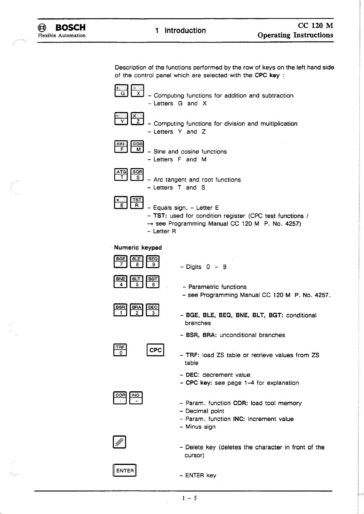
Description of the functions performed by the row of keys on the left hand side
of the control panel which are selected wlth the
- Computing functions for addition and subtraction
- Letters G and X
- Computing functions for division and multiplication
- Letters Y and Z
Operating
CPC
key
:
120 M
Instructions
ISI~llc~1
IA~GIIS~RI
.
Numeric
IB~EIIB~lla~ol
_Sine and eosine funetions
- Letters
_Are tangent and root funetions
- Letters T and S
- Equals sign, - Letter E
- TST: used for eonditlon register (CPC
-+
see Programming Manual
-
letter
keypad
Fand
R
- Digits 0 - 9
- Parametric functions
- see Programming Manual CC 120 M
-
M
BGE.
BlE.
branches
CC
BEQ.
BNE.BlT. BGT: eonditional
t20 M
test
funetions !
P.
No. 4257)
P.
No. 4257.
- BSR. BRA: uneonditional branehes
- TRF: load ZS table
table
-
DEC:
deerement value
-
CPC
key: see page
- Param. funetion
- Decimal point
- Param. funetion INC: Increment value
- Minus sign
- Delete key (dele1es the eharaeter in front of the
cursor)
ENTER
-
1 - 5
key
or
retrieve values
1-4
COR:
load tool
for explanation
memory
from
ZS
Page 16
@ BOSeH
Flexible
Manual panel
Automation
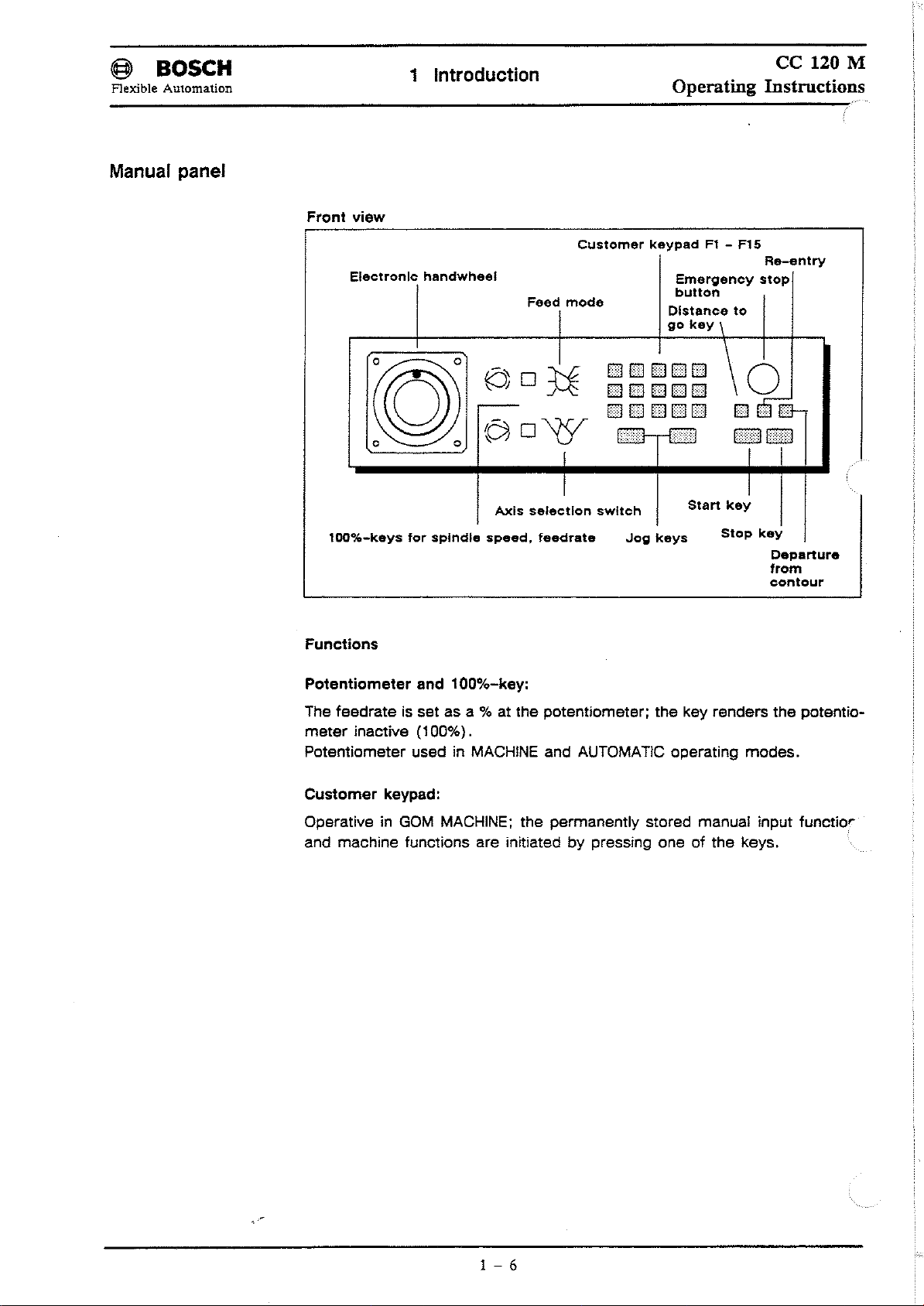
Front
view
1 Introduction
ce
120 M
Operating Instructions
Electronlc
100%-keys
Functions
Potentiometer
handwheel
Axis
tor
spindie
and 100%-key:
speed,
Feed
mode
selectlon
feedrate
Customer
keypadFI-
E1E1E1E1EJ
E1EJEJDEJ
EJEJEJEJEJ
==
""'"'
swltch
Jog
Emergency
button
Distance
go
key
=
==
Start
keys
FI5
Re-entry
stop
to
\
\0
E11IJ-
Eill:HBIB
key
Stop
key
Departure
trom
contour
The feedrate is set as a % at the potentiometer; the key renders
meter
Potentiometer used in MACHINE and AUTOMATIC operating
Customer
Operative in
and maehine tunetions are initiated by pressing one
inaetive (100%).
keypad:
GOM
MACHINE; the permanently stored manual input funetior
of
the keys.
modes.
the
potentio-
1 - 6
Page 17
(§l
Flexible
BOSCH
Automation
1 Introduction
Operating
ce
120 M
Instructions
Control elements of
the
manual panel
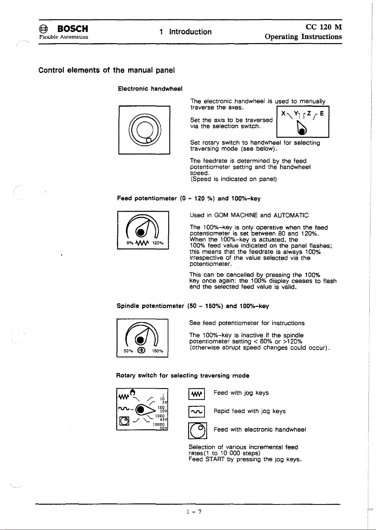
Electronic
potentiometer
Feed
0%
ANV'
handwheel
120%
The eleetronie handwheel is used to manually
traverse the axes.
Set the axis to be traversed
via the seleetion switch.
Set rotary switch
traversing
The leedrate is determined
potentiometer setting and the handwheel
speed.
(Speed is indicated on panel)
(0 - 120 %) and
Used in
The
potentiometer is set between 80 and 120%.
When the 100%-key is actuated. the
100%
this means that the
irrespective
potentiometer.
mode
GOM
100%-key
leed
to
handwheel
(see below).
100%-key
MACHINE
is only operative when the
value indieated on the panel flashes;
01
the value seleeted via
and AUTOMATie
leedrate
lor
selecting
by
the
leed
is always 100%
leed
the
Spindie
potentiometer
atu
50%
@)
Rotary
switch
150%
lor
This ean be cancelled by pressing the 100%
key
and the selected
(50 - 150%) and
See
The 100%-key is inactive il the spindie
potentiometer setting
(otherwise abrupt speed changes could oeeur).
selecting
I
Wo/'
I
'V'\.o
~
Selection
rates(1to
Feed
once
again: the 100% display ceasestoflash
leed
potentiometer
traversing
leed
100%-key
mode
value is valid.
lor
instructions
< 80%
or
>120%
I Feed with jog keys
I Rapid
STARTbypressing the
leed
with jog keys
Feed with eleetronic handwheel
01
various incremental
10 000 steps)
jog
leed
keys.
1 - 7
Page 18
@ BOSeH
Flexible Automation
1 Introduction
Operating
ce
120 M
Instmctions
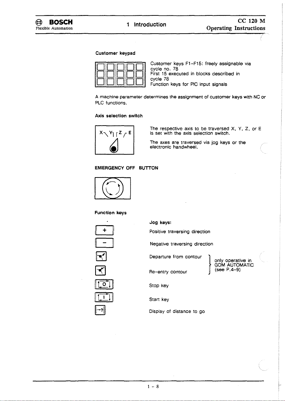
Customer
A machine parameter determines the assignment
PLC
Axls
EMERGENCY OFF BUTTON
keypad
lunctions.
selection
switch
Customer keys F1-F15: Ireely assignable via
cycle no. 78
First
15
executed in blocks described in
78
cycle
FunClion keys
The respective axis to be traversed
is set with the axis selection switch.
The axes are traversed via jog keys
electronic handwheel.
lor
PIC
input signals
01
customer
keys with NC
X.
Y,
Z,orE
or
the
or
Function
keys
[!]
c:J
~
~
~tIjll
II[D~
BI
Jog
keys:
Positive traversing direction
Negative traversing direction
from
Departure
Re-entry contour
Stop key
Start key
Display
01
contour
}
distance to go
only operative in
GOM AUTOMATIC
(see
P.4-9)
1 - 8
Page 19
~
BOSCH
Flexible Automation
1 Introduction
ce
120 M
Operating Instructions
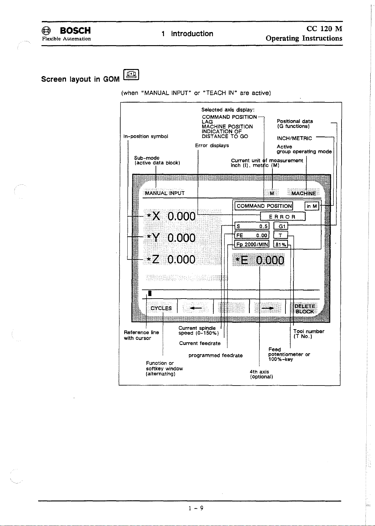
Screen layout in
GOM
I
([iJJ
I
(when "MANUAL INPUT"or"TEACH IN" are active)
Selected axls display:
COMMAND POSITION
LAG
MACHINE POSITION
ln-position symbol
Sub-mode
(actlve
data
block)
OIO()
INDICATION OF
DISTANCE
Error
displays
t
-t:C:o:M::M=A~NrD=P~O~S~I~T~IO~N=;;-_jlln
TO
GO
Current unlt
Inch
(I).
met
S
Posltional
(G lunctlons)
INCH/METRIC
Actlve
group operating
data
mode
MI
Reference line
with
cursor
Function
softkey
(altemating1
Current spindie
speed (0-150%)
Current
cr
window
feedrate
programmed teedrate
4th
axis
(optionai)
Tool
(T
Feed
potentiometer
100%-key
number
No.)
cr
1 - 9
Page 20
@ BOSCH
Flexible Automation
Operating instructions
1 Introduction
ce
120 M
Operating Instructions
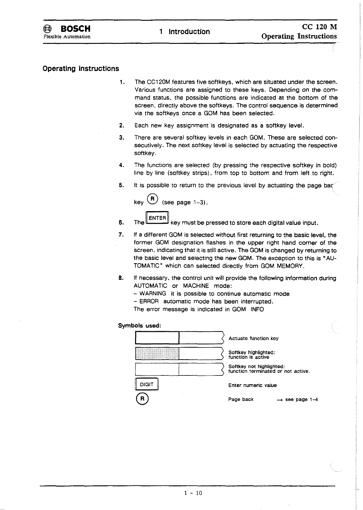
1. The CC120M leatures live soltkeys. whieh are situated
Various lunetions are assigned
mand status. the possible lunetions are indieated at the bOllom01the
sereen, direetly above the soltkeys, The eontrol sequenee is determined
via the soltkeys onee a
2.
Eaeh new key assignment is designated as a
3. There are several soltkey levels
seeutively. The next soltkey level is seleeted by aetuating
softkey.
4, The funetions are seleeted (by pressing the respeetive
line by line (soltkey strips).
5.
It
is possible to returntothe previous level
key ® (see page
11
6.
7.
ENTERII
The key must be pressedtostore eaeh digital value input.
II a different
former
sereen, indieating that it is still aetive. The
the basie level and seleeting the new GOM. The exeeption
TOMATIC" whieh ean seleeted direetly
GOM
is seleeted without
GOM
designation Ilashesinthe
GOM
1-3).
to
these keys. Depending on the
has been seleeted,
in
eaeh
GOM,
Irom
toptobOllom and
lirst
returningtothe basie level. the
upper right hand
GOM
from
soltkey
These are seleeted eon-
by
aetuating
is ehangedbyreturning to
GOM
under
level.
the
soltkeyinbold)
lram
the
eorner01the
to
MEMORY.
the sereen.
eom-
respeetive
lefttoright.
page
bat?
this is
"AU-
8.
II
neeessary. the eontrol unit will provide the following information during
AUTOMATIC
-
WARNING
-
ERROR
The error message is indieated
===~======:
'-
or
MACHINE
it is possible to eontinue automatie
automatie mode has been interrupted,
mode:
in
S
Actuate
Softkey highlighted:
functionlsactive
) Softkey not highlighted:
>functlon terminated or not active.
Enter numeric
Page back
GOM
INFO
functlon key
vaiue
mode
-+
see page
1-4
1 -
10
Page 21
Page 22

Page 23
@ BOSCH
Flexible
Automation
Memory
[2]
ce
120 M
Operating Instructions
GOM
MEMORy[2]
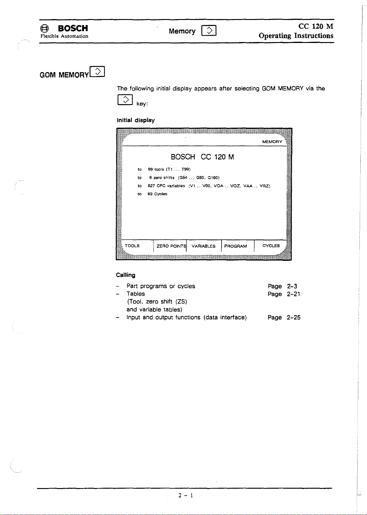
The following initial display appears after selecting
[2]
key:
Initial display
to
99
tools
to6zero
to
827
to
69
Cycles
CPC
BOSCH
(Tl
>
shifts
variables
••
(G54
T99)
CC
...
G60,
(V1..V99,
VARIABLES
120
G160)
VOA..VCZ,
M
VAA..VR2)
GOM
MEMORY via the
MEMORY
Calling
or
Part programs
cycles
Tables
(Tool. zero shift (ZS)
and variable tables)
Input and output functions (data interface)
Page
2-3
Page 2-21
Page
2-25
2 - 1
Page 24
@ BOSCH
Flexible Automation
MEMORY general
Memory
[2]
ce
120 M
Operating Instructions
Memory
Inputofinformation
Outputofinformation
Typesofprotection
Unauthorised access (read, write and delete) can be prevented via the
keys. The executionofcycles is always authorised.
Types of protection are indicated as folIows:
for
input
and
editing
part programs (max.999 999 999/limited by
max.
69
cycles,
max. 48 tool compensations
parameter table for max. 48 tools (99 tools optional) ,
tool Iife,
max. 6 zero shifts per axis and 2 additional
1035
CPC
max.
keypad
interfaces V24/20
interfaces V24/20mA (port
(EDIT)
variables, 208 of which are reserved
via:
and
mA
via:
of:
memory
(99
tools optional),
zero
shifts
(port1)and/or V24 (port 2).
1)
and/or
V24 (port 2).
capacity) •
for
MTB.
soft-
RWEO
RE
E Execution only authorised
o The
o
Read, Write,Execute,Delete authorised
Read and execute authorised
,
By
actuating the
"E"
type of protection can onlybeactivated in
word
only
for
cycles
Apart
order to select
program must first be converted into a cycle (see
the
read protection function.
must be entered via "MTB SERVICE" .
~-'---~
SK
PROTECTION
ON/OFF
(see
P.2-10).
GOM
INFO. The
page
2-13)
code-
2 - 2
Page 25
I@
Flexible Automation
Part programs or cycles
BOSCH
Memory
o Part programs/cycles can be
- edited (edit. insert, regenerate or search for texts),
- input and output.
- deleted,
- renamed,
- copied,
-
or
renumbered.
o Part programs can be
- converted to cycles (but not visce versa).
--+ For information on c y c 1e s see page 2-15.
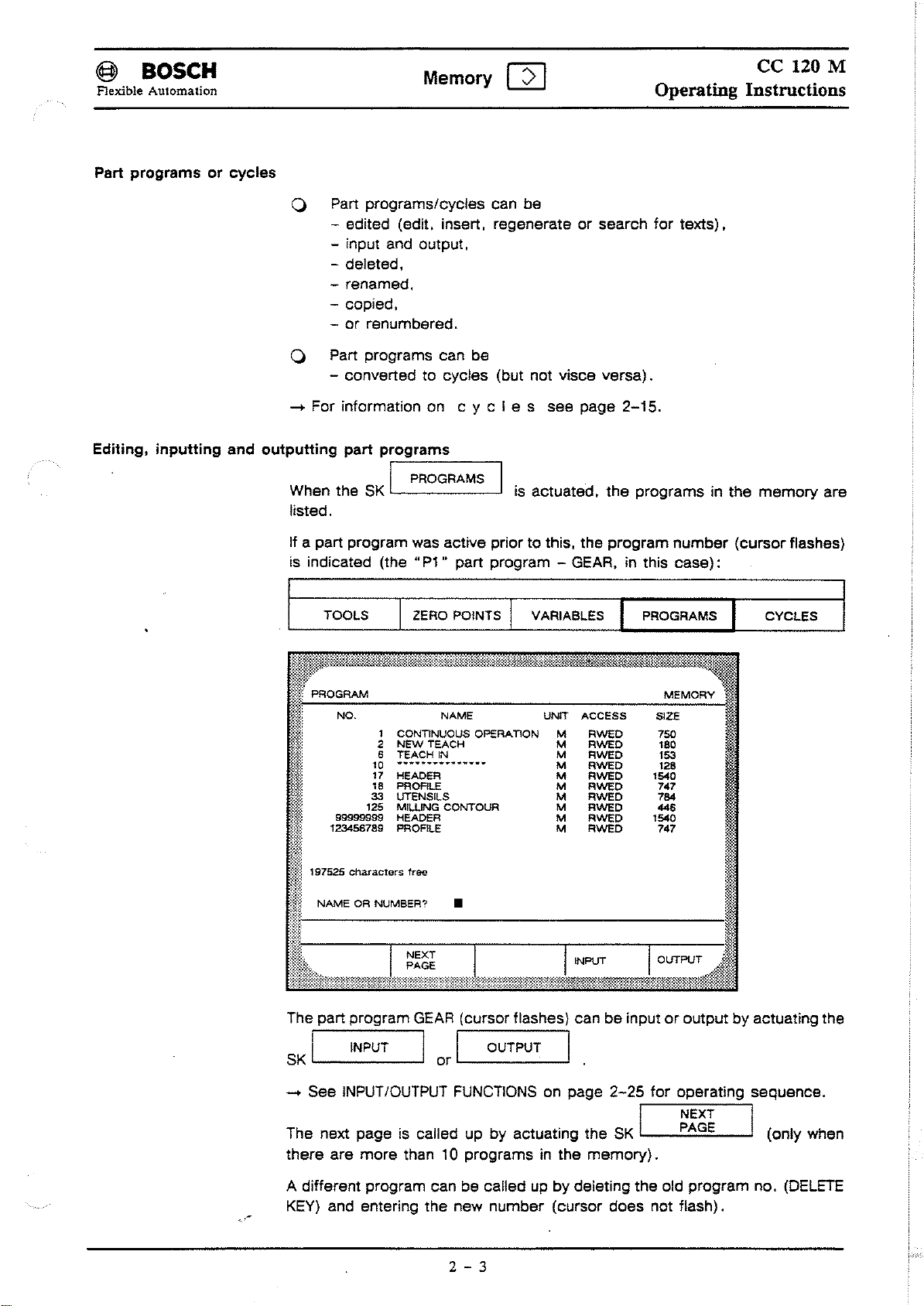
Editing, inputting and outputting part programs
PROGRAMS I
When the
listed.
SK
I
[2]
is
actuated,
Operating Instructions
the
programs in the
ce
120 M
memory
are
apart
If
is indicated (the
program was active prior to this, the program
"P1"
part program -
TOOLS I ZERO POINTS r VARIABLES I PROGRAMS I CVCLES
GEAR,inthis
number
case):
(cursorflashes)
The part program
SK
I INPUT IorI OUTPUT I.
--+ See
The next page is called up by actuating the
there are more than
A different program can be calied up by deleting the old program no.
KEY)
INPUT/OUTPUT
and entering the new number (cursor does not flash).
GEAR
(cursor flashes) can be inputoroutput by actuating the
FUNCTIONS
10 programs in the
2
- 3
on page
memory).
2-25
for operating sequence.
SK
I
~;~~
I (only when
(DELETE
Page 26
@l
BOSeH
Flexible Automation
Memory
C8
ce
120 M
Operating Instructions
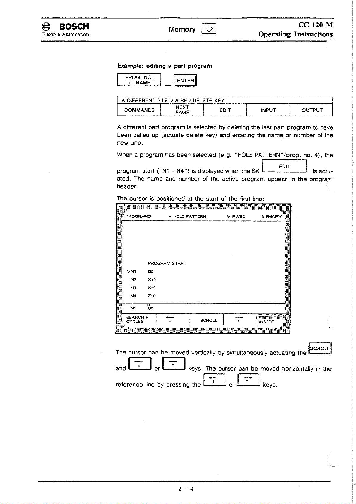
Example: editing
PROG. NO. I
or
NAME .
A DIFFERENT FILE VIA
COMMANDS
A different part programisselected by deletlng
been called up (actuate delete key) and entering the
new
one.
When a program has been selected (e.g. "HOLE PATIERN"/prog. no.
program start
ated, The name and number of the active program appear
header.
The cursor is positloned at the start of
apart
_~
~
T NEXT I EDIT
("N1-N4")
~
ENTER
RED
PAGE
program
~
DELETE KEY
Is
dlsplayed when the SK I EDIT I
the
MRWED
I
the
first line:
INPUT I OUTPUT
last part
nameornumber
MEMORY
program
In
the
to have
of the
4),
the
Is
actu-
prograr
N2
PROGRAM
GO
X10
I
>Nl
I
;:;:~.:
The cursor can be moved vertlcally by simultaneously actuating
and
~
reference line by pressing the
START
or [[Z]] keys. The cursor can be moved horizontally in the
~
or
iC1:J]
keys.
the
IlsCROLyl
2 - 4
Page 27
@ BOSCH
Flexible Automation
Memory
[2]
ce
120 M
Operating Instructions
Editing a
program
line
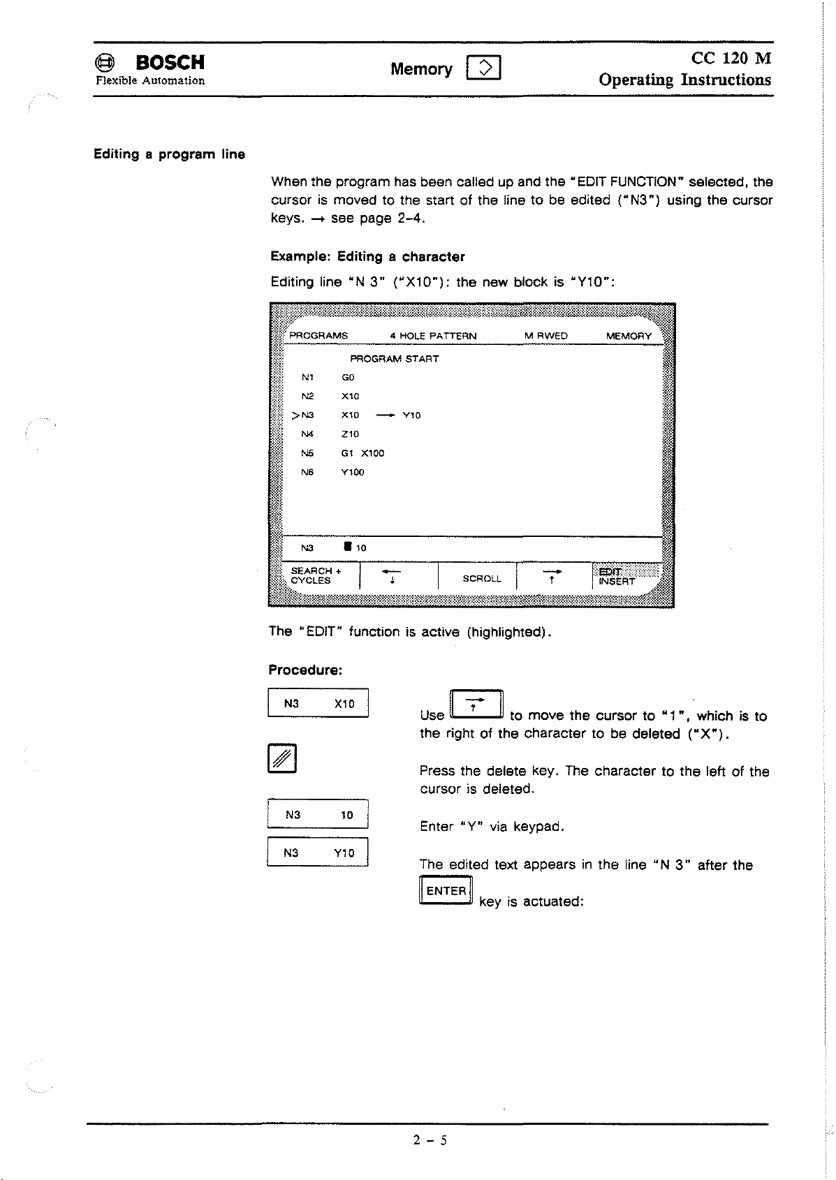
When the program has been called up and the "EDIT FUNCTION" selected, the
cursor is moved to the start
-+
keys.
Example: Editing a
Editing line "N
};:~~
~~j
see page
PROGRAM
Nl
GO
Xl0
N2
N4
N5
N6
Xl0
Z10
Gl
Yl00
>N3
2-4.
character
3"
("X10"):
4 HOLE PATTERN
START
Yl0
-
X100
of
the linetobe edited
the new blockis"Y10":
MRweo
("N3")
MEMORY
using the cursor
I
1--N3---.-,0------------------
The "EDIT" functionisactive (highlighted).
Procedure:
I
N3
N3
N3
X10
10
Y10
Use [I2JI to
the right
Press the delete key. The charactertothe
cursor is deleted.
Enter
The edited text appearsinthe
~
ENTER
of
"Y"
~
key is actuated:
move
the
character to
via keypad.
the
cursorto"1",'
be
deleted
line
"N
which is to
("X").
leftofthe
3"
after the
2 - 5
Page 28
@
BOSCH
Flexible Automation
Memory
[2]
ce
120 M
Operating Instructions
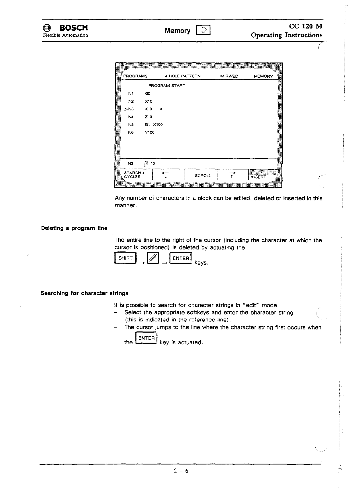
Any
manner.
Deleting a program line
The entire !inetothe rightofthe cursor (including the
cursor
11
SHIFT
Searching for character strings
It is possibletosearch
numberofcharacters in a block can be edited, deletedorinserted in this
character
is positioned)isdeleted by actuating the
~
I# I
-+ -+
Select the appropriate softkeys and enter the
(this is indicated
The cursor jumps to the line where the character strlng first
~
ENTER
the keyisactuated.
~
11
ENTER
in
~
keys.
for
character strings in
the reference !ine).
"edit"
character
mode.
at which the
string
occurs
when
2 - 6
Page 29
@ BOSeH
Flexible Automation
Memory [2]
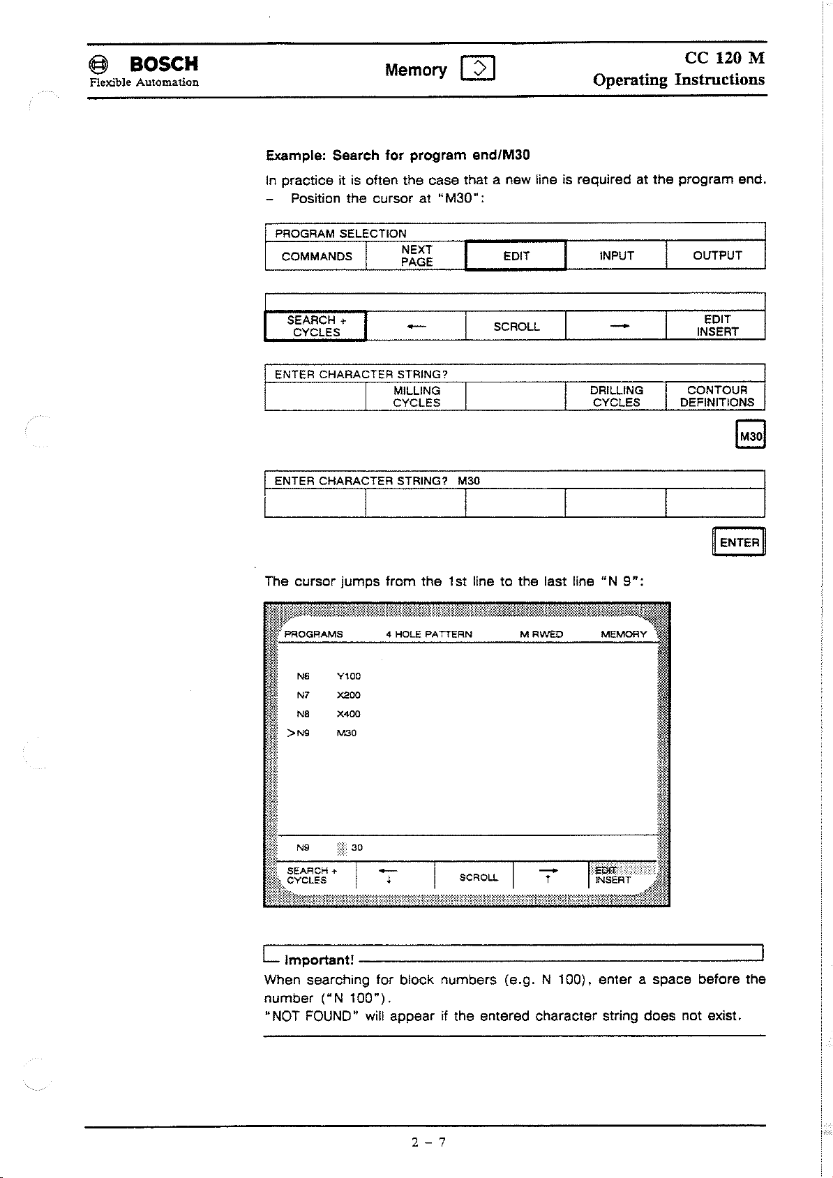
Example: Search tor program end/M30
In
pracliceilis
Position the cursor at
PROGRAM SELECTION
COMMANDS
otlen the case that a new line is required at
"M30":
I NEXT
PAGE
EDIT
I
ce
Operating Instructions
the
program end.
INPUT I OUTPUT
I
120 M
SEARCH
CVCLES
ENTER CHARACTER STRING?
ENTER CHARACTER STRING? M30
__
The cursor
+
MILLING I
I
CVCLES
I 1
jumps
Yl00
><200
X400
MOO
trom
-
the 1st line 10 the last line
SCROLL
I
-
DRILLING
CVCLES
"N
9":
INSERT
CONTOUR
I
DEFINITIONS
,.
EDIT
~!
L Important!
When searching tor block numbers (e.g. N 100).
number
"NOT FOUND" will appear it the entered character string does not exisl.
-----------------------'
("N
100").
2 - 7
enler
aspace
betore the
Page 30
@>
BOSeH
Flexible Automation
Memory
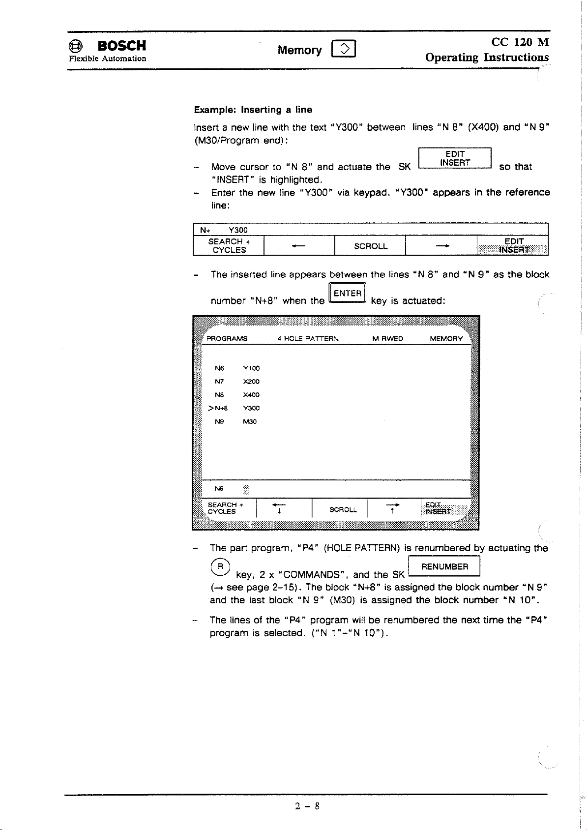
Example: Inserting a line
[2]
ce
120 M
Operating Instructions
Insert a new line with the text "Y300" between
(M30/Program
Move cursor to "NS"and actuate the
"INSERT" is highlighted.
Enter the new fine
fine:
N+
Y300
SEARCH + I
CYCLES
The inserted
number "N+S" when the key is actuated:
end):
"Y300"
-
fine
appears between the fines"NS" and
via keypad. "Y300"
SCROLL I
I
~
ENTER
~
lines"
N S" (X400) and"N9"
SK
I_-,-IN"ES::.~::;I~"T,-_I
appears in
so that
the
relerence
-
"N9"as
the
block
~j!~::~~~i%Wjt'l~jl::~'::~:~~~i!lWMlli~~:@NM&=~'
J:
::
I
F~::
11'-----------------------
lf:~
N9
a SEARCH + I - I I
i:I;li,t:~~~:1wim;;wH1#:m'i!i'wlf:'i!",l
The part program,
fR\ I RENUMBER I
v key, 2 x "COMMANDS", and the
(-+
see page
and the last block
The fines01the
programisselected.
2-15).
"P4"
"il:;::~:<)1#Mm:::1!1!l%;~:::;iM
"P4"
(HOLE
The block "N+S" is assigned
"N
9"
program will be renumbered the next
("N
PATIERN) is renumberedbyactuating the
(M30)isassigned the block
1"-"N
10").
SK
LEOrt
'---------'
the
I
block
number
number"N
"N
10".
time
the
9"
"P4"
2 - 8
Page 31

@ BOSCH
Flexible Automation
Memory
Renaming programs
[2]
ce
120 M
Operating Instructions
Rename the part program
(the prog. no. remains unchanged).
The user is requested
RE
I
SK
Enter the new part program name "CONSOLE" and press the key.
"CONSOLE" now appears (as
NAME I
"P4"
(HOLEPATIERN) as "CONSOLE"
to
enter the new name of "P4 "/CONSOLE when the
has been actuated (highlighted).
~
ENTERII
"P4")inplace of "HOLE PATIERN":-+see page
2-4.
TOOLS
COMMANDS
COMMANDS
IZERO POINTS I VARIABLES I PROGRAMS I
I_.......:~~;:::~~~=-_L-
I PROTECTION I
ON
OFF
__
METRIC
E_D_IT
__
INCH
..L
I
__
I_N_P_UT
DELETE
I
CYCLES
O_U_T_PU_T
RENAME
__
Enter
CONSOLE
NEW
NAME?
COMMANDS
·"'··':@tm!MfttW.1W1WM!WMiliMBI[MMni%'MiMt~illMt~i:K.~W?@it~'~~
NO.
Mi
123456789
I
~I
@~
197525 characters free
..
~'.'.
t.~~.:~
NAME
~
~~!i,-
1
2
6
10
17
1B
33
125
99999999
OR NUMBER'"
CONSOLE
PROTECTION INCH
ON
OFF
4 CONSOLE M
NAME
CONT1NUOUS OPERATION M
NEW
TEACH M
TEACH1N M
.........................
HEADER M
PROFILE
UTENSllS
M1LLlNG
HEADER
PROFILE
CONTOUR
, .
METRIC
UNrT
M
M
M
M
M
M
Rweo
ACCESS
RWEO
RWeD
RWeO
RWED
RWED
RWeO
RWED
RWED
RWED
RWED
DELETE
MEMORY
srZE
750
lBO
153
128
1540
747
784
446
1540
747
~
ENTERII
::tt
rt
r.~
~1
W
~«::.
;::;::
.~.~
.•.
'.~.;
".
~.~
•..
~
..
,~.:t
....';..;'..'..:;..
i.:"·:":':'.""
•••••
:••'..•
,c
....:.•...•...•..•
o
..••...••.•.
M:,
.••••.MA.•.:,.••.••..•
::N
••.•.
:.D
••..
•.•
m.
S RENAME
,.::;:::,:••":""".:.:".,,.
, ".:.,
::::.:.:.:::
••
K;wmll!%.::nw::.;%,@m~@.::m111~i
2 - 9
I.
Page 32

@l
BOSCH
Flexible Automation
Deleting a program
Apart
program ean be deleted by seleeting the
Memory
Q]
ce 120 M
Operating Instructions
PROGRAMS I
I
SK
L . (enter
PROTECTION ON/OFF
prog.
no.),
COMMANDS I I DELETE I
I
and
...J
r===::":':>
First deaetivate the delete proteetlon.-+see
PROGRAM SELECTION
COMMANDS
COMMANDS
The programIsdeleted
aetuated.
I NEXT
PAGE
I PROTECTION I
ON
OFF
from
EDIT
I
INCH
METRIC
the program list when the key is
SK
,-_O=N,.....:O",F",F_..J
I
DELETE
I
L Important!
Only one program ean be deleted at a timeInthe
The write proteetlon is aetlvated or deaetlvated
PROTECTION
INPUT
~
GOM
[2J
by
seleeting
I OUTPUT
RE
I
NAME
ENTER~
---'
the
SK
PROTECTION OFF
PROTECTION
ON
I COMMANDS
The eurrent typeofwrlte proteetion is IndleatedInthe program list via
RWED.
j COMMANDS
COMMANDS
RWED:
RE:
land
I PROTECTION I
ON
READ,
only read and exeeute authorlsed.
-+
see page
P~~TEC6~~N
NEXT
PAGE
OFF
WRITE,EXECUTE,DELETE
2-2,
Types of proteetion
EDIT INPUT
INCH
METRIC
DELETE I RENAME
I
authorlsed.
OUTPUT
RE
or
2 - 10
Page 33

i§
BOSCH
Flexible Automation
Memory [2J
Operating
ce
120 M
Instructions
Unilsofmeasuremenl
(inch/melric)
The unit of measurementofa programora cycle is defined by using the
I
MI~,c~C
ICOMMANDS
COMMANDS I PROTECTION I
When the
measurement M (for metric) or I (for inch)
after each program
L
Noles
1. Default status for
-
GOM
-
GOM
I
l_---'~~;:::~~~=-
ON
OFF
I PROGRAMS I
SK
or
cycle name (in the unit column).
on
unilsofmeasuremenl
MACHINE:
MEMORY
+ AUTOMATIC:
E_D_IT__,--_I_N_P_U_T
INCH
METRIC DELETE RENAME
is actuated, the programorcycle unit of
-------
I I
is
displayedinthe header line and
presetting
presetting
GOM
INFORMATION
GOM
MEMORY
O_U_T_P_U_T_
SK
_
2.
When
GOM
MACHINE
I
<81
GOM
in
-
In
GOM
MACHINE, the unit of measurement can be defined irrespective
of the presetting (in
- When
3.
- The unit of measurement selected in
GOM
preset in
In
GOM
MEMORY
cycle can be set individually.
header.
is the presetting for
(and not
INFO
MACHINEisexited and reselected, the unit of measurement
GOM
INFO
GOM
INFO).
is
seiected I
is active.
GOM
INFO).
is active.
[2J the unit of measurement for every program or
GOM
AUTOMA
"'"
iEb
Ithe unit of measurement preset
or
"M"
is displayedinthe program
GOM
Tici
MEMORY
:=J
I
for
a program/cycle
2 -
11
Page 34

@ BOSCH
Flexible Automation
Memory
[2]
ce
120 M
Operating Instructions
Copying a
program
Apart
Example:
"MILLING":
j
program ean be eopiedbyseleeting
COMMANDS
COMMANDS
NEW
NAME?
COPY
the
copying
the
parl
program
1,--_p:..;NA:..;E~::;~=-
I
PROTECTION
ON
OFF
COPY
I
"P4"
ED_I_T__,-
INCH
METRIC
PRGM
TO
CYCLE
PRGM
TO
CYCLE
(CONSOLE)
I
SK
L
__
IN_P_U_T
DELETE
I
RENUMBER 1
RENUMBER
under
the
I
---L
new
name
O_U_T_PU_T
RE
NAME
of
__
-'
~
Enter new program name: MILUNG
NEW
NAME?
The eopied program "CONSOLE" will be stored in the next available
memory
(the original program "P4/HOLE PATTERN" thus remains unehanged)
New name:
File stored with no. 0
MILLING
loeation underthe new name "MILUNG" - in this ease, under
MILUNG
ENTER
PRGM
CYCLE
TO
~
RENUMBER
I
ENTERI
"PS"
2 - 12
Page 35

@ BOSCH
Flexible Automation
Converting programstocycles
A program can be renamedasa cycle by selecling
"COMMANDS" key and
Memory
lhe
[2]
PRGMTOCYCLE
ce
Operating Instructions
lhe
PROGRAM
key.
softkey, 2 x
120 M
Example: Converting
I
PROGRAM
r
~=======C=O=p=y===:P:R:G:M=T:O===R=E=N=U=M=B=E=R=~=====1
SELECTlONI
~~OO?
'--
lhe
part program "P4"/HOLE
.....
I 2 x
C_O_p_y__llllil_R_E_N_U_M_B_ER_
COMMANDS
CYCLE
PATTERN10cycle 20
I
.
I
----.."""
EI
I
CYCLE
NAME?
_________
NO,20
I
COPY
C_O_P_Y
__
PRGM
TO
CYCLE
RENUMBER
I
L----:P~::.~.:.:~~L~~:...o_1
REN
UMBER
I
0GGJ00000
~~~1:
197525 characters free
~n:
2 -
13
Page 36

@ BOSeH
Flexible Automation
Renumbering
Memory
The block numbersinapart
[2]
program are renumbered consecutively
Operating Instructions
ce
120 M
byactuat-
ing
the
sertedordeleled. The following appears in the reference line when
gram has been renumbered:
"RENUMBERED".
Branch labels and subprogram
Example: inserting a program
The following procedure is used10insert
"Y300" and renumber the part program (
COMMANDS
N+
SEARCH +
CYClES
IRENUMBER
SK
Y300
NEXT
PAGE
-
•
I
. This functlonISused when
call-ups
Une
are also
and renumbering
Ihe
new line "N+B" wilh
.....
see page 2-Bl:
EDIT
SCROll
blocks
re-calculated.
INPUT
-
r
have been in-
apart
Ihe
OUTPUT
pro-
text
®
COMMANDS I PROTECTION I
RENUMBER
ON
OFF METRIC
COPY
COPY
INCH
PRGM
CYClE
PRGM
CYClE
TO
TO
DElETE
I
RENUMBER
RENUMBER
OUTPUT I
RENAME
I
I
I
2 - 14
Page 37

§ BOSCH
Flexible
Cycles
Free
Automation
cycles
ce
Memory
A distinction is made between freely programmable cycles and thosewhich
perform fixed functions.
Machining processes which occur repeatedly are stored in the cycles.
Free cycles are those between 1 and
vided they are notinuse by the
[2]
Operating Instructions
69. These cycles are freely available
MTB.
120 M
pro-
Cycles
with
fixed
functions
Selection in
TOOLS I
PROGRAMS
I
or'-------
SEARCH + I
CYCLES
FREE
Cycle
Cycle
-
Cycle
-
Cycle
-
Cycle
-
Cycle
GOM
MEMORY
ZERO
-
C~STOMER-SPECIFlf
74
75
76
77
78
79
, .
via:
POINTS I VARIABLES I PROGRAMS I CYCLES
-
•
Emergency
»TB
cycle
MTB
cycle
MTB
cycle
Function
on
the
bit
11onNe
-+
see
Reference
SCROLL I
I
CYCLES
routine
assignments
customer
PLC
page
1-8
cycle
(call-up
(call-up
(call-up
keypad and
digital
for
I
with
with
with
t
DRILLING
CYCLES
11122)
11121)
Me)
keys
Fl
bits
interface
0-7
EDIT
INSERT
I
CONTOUR
DEFINITIONS
I
to
F15
cf
output
-+
see Programming Manual ce 120 M P.-No.4257.
2 -
15
Page 38
@ BOSCH
Flexible Automation
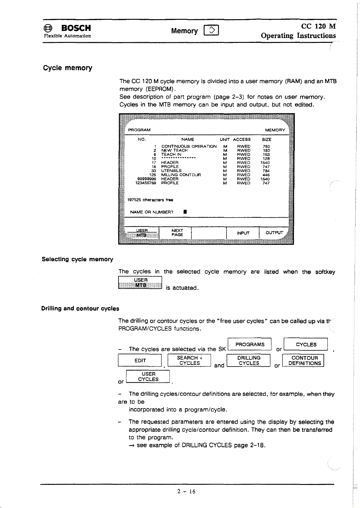
Cycle memory
ce
Memory
The
CC
120 M cycle
memory
See description of
Cycles in the
!1~)i~~wm%:*Im~~~Hl§~@mW~@~~n1~:?1}~WM11~~lli~;~~~m:~:~:i~m~J~l~fllimmllißt.~=t:i~:ililt:i~~%*t~
W
(EEPROM).
PROGRAM
memory
part program (page
MTB
memory
[2]
is divided into a user
2-3)
can be input and output. but
Operating Instructions
memory
for notes on
MEMORY
(RAM) and an
user
not
edited.
120 M
MTB
memory.
Selecting cycle memory
Drilling
end
contour cycles
I
&~f:
M~
a:
~,,~,
I
The cycles in the selected cycle
~-,-,;:((~f~i
NO
~
~~~~';,;:~PERATION
::";~
~~:::;
~~I
123456789 PROFILE M
'97525
NAMEORNUMBER?
6 TEACH IN M
10 M
99009~~
characters free
~~~i~ONTOUR
•
-,-,:1
is
actuated.
u~
A;~;g
RWED
RWED
~
~~II
RWED
memory
~~E
153
128
:E
747
are Iisted when
the
softkey
The drillingorcontour cyclesorthe..free user
PROGRAM/CYCLES functions.
SK
The cycles are selected via the
EDIT
I
USER
J
are to be
CYCLES
The drilling cycles/contour definitions are selected.
incorporated into a program/cycle.
The requested parameters are entered using the display
appropriate drilling cycle/contour definition. They can then be transferred
to
the program.
.... see example of
I I
SEARCH +
CYCLES CYCLES DEFINITIONS
I
DRILLING
2 -
16
I
land
CYCLES page
cycles"
PROGRAMS
DRILLING CONTOUR
2-18.
can becaliedupvia
I or I
or
for
CYCLES
example, when they
by
selecting the
t~
Page 39

@ BOSCH
Flexible Automation
Memory
[2]
ce 120 M
Operating Instructions
Drilling
cycles
Seleet the eyeles as
displayed when
I
EDIT
SEARCH
CYCLES
theSKl--.....:::C..:-YC:::L",E:.::S,--...J
I
+ I
I
I
described
,
-
USER
CYCLES
above.
DRILLING
I
I
I
A selection01the
is
actuated:
SCROLL
I
I
-
t
DRILLING
CYCLES
available
I
I
CONTOUR
DEFINITIONS
cycles
EDIT
INSERT
is
Select the
I
L
Important!
softkey
The
out
in GOM INFO. They willnolonger
internal
erated.
desired
OK
MTB
I
--
DRILLING CYCLES
cycles
eycle via
(GOM
INFO
-+
ONL
the
cursor
and/or
I MTB SERVICE -
Y POSSIBLE WITH CODEWORD ....
keys
and
the
softkey
CONTOUR DEFINITIONS
appearinthe
soltkey
enter
codeword)
strip. Furthermore.
_
canbemasked
canbegen-
2 - 17
Page 40

@ BOSCH
Flexible Automation
Memory [2]
ExampleofDRILLING CYCLES
ce 120 M
Operating Instructions
The following praetieal example illustrates how drilling eyeles
The cyele "GB4/TAPPING" is to be inserted into
number
Before generating the program. aetuate the SK
..
INSERT" is aetive (highlighted).
Enter the following program
NI
N2
N3
N4
N5
N6
N7
NB
N9
Nl0
NIl
N12 M5
N13
N14 M6
N15 T0202
N16 S450
N17
NIB
"N
17".
G90
M6
T010l
S1000
GO
Fl000
GB2VI=0
Xll0
YBO
GO
GBO
TOO
GO
Xll0
M3
Z20
Y40
Z20
M3
Z20
Y40
in
(GOM
MEMORY):
V2=-50
V3=2 V4=0
The "TAPPING CYCLE
iscalied up here and inserted in the
84"
apart
program
1_.....:;.IN;:;:Es":.=~::..~'-'T_--J1
program.
are
called up.
under
the
so
block
that
__
S~~~~~~;;;fE:;:HS;:.+
I
Seleet the"TAPPING" eyele by aetuating the
The nameofthe seleeted drilling eyele then flashesintheseleetion menu (page
2-17)
.
-_"
__
MILLING
CYCLES
2 -
-'-__S_C_R_O_L_L
I I
18
DRILLING
CYCLES
cursor
-_T
key
lC:Z:Jl
~',mf~~}jI
I
CONTOUR
DEFINITIONS
J
.
Page 41

@ BOSeH
Flexible Automation
Memory [2]
ce
120 M
Operating Instructions
The
"tapping"
graphics are displayed when the
SK
IL
ated:
~~~~iMii!lITiMii!lIT~
PROGRAM
TAPPING
G84
V3=3er4 for
spindie
V4=1eed
MM/REV
Nll
M3/M4
in
G84
'6
Ref. level
V1
~
r
V2
1
1
V1= 0 V2=
-10
V3=3
MRWED
•
V5=dweil
V4=
1.5
V5=
Machining-specific values are assignedtothe parameters
~+
G84
Vl=O
V2=-10
V3=3
V4.;.=.;.1"',S.;..;.V'-S_=O"-_.,-
MEMORY
t;me
0
O_K__
"V1-VS":
is actu-
_
L.
__
I
The "tapping
---1.,
cycle"
, TAB -
is translerredtothe program when the key is
actuated:
N17
G84 V1=0 V2=-10
N18
X20 Y20
N19
G80
N20
Z20
N21
M5
N22
TOO
N23
M2
The cycle "G84/T
V3=3
APPING"
V4=1.5 V5=0
appearsinplace01X20/Y20 the next time the
part program (Ior "AUTOMATIC") is called up.
11
ENTER
~
2 - 19
Page 42

(§l
BOSCH
Flexible Automation
Contour cycles
Memory
[2]
ce
120 M
Operating Instructions
The
_
The
contour
CYCLES
COMMANDS
SEARCH
CYCLES
See
"Important"
following contour cycles are available:
cycles
I
I
I
+
I I I
MILLING
CYCLES
@j@llt?MMH~gmtm@]tHM®mMittl@~@ill@fltii1tÜ©llitt.
NEXT
PAGE
,
page
are
selected
EDIT
2-16.
Connection Connection
I
,I
EDIT
SCROLL
via
SEARCH
CYCLES
the
+
DRILLING
CYCLES
SK
land
INPUT
-
t
PROGRAMS
CONTOUR
DEFINITIONS
OUTPUT
EDIT
INSERT
I
CONTOUR
DEFINITION
I
or
%i
WJ.
t:{[.
lnt81'"S.
~ll1
pt. inters. pt. 2 points 1 point +
2 elreles lIne/clrcle 2 angles
Chamfer
I~~~~
lJl
;~~I;,sit;on
When
gene
ming
aid
_
See
Programming
drilling/contour
rating
for
it::
programs,
difficult
cycles.
~~:
~n
the
above
and
complex
Manual ce 120 M
contours.
:~:;;~t
contour
P.-No.4257
definitions
for
detailed
serve
as a
program-
information
on
2 -
20
Page 43

~
Flexible Automation
BOSCH
Tables
The lollowing tables are available: the tool/parameter table (Ior max. 48 tools;
ean be extended up to 99 tools). the zero shilt table(G54
G160) and the variables table.
Tool table / parameter table
The lunetions edit. input and output (see "Input/output lunetions") eanbeseleeted
tables) .
Important: The MT8 may have disabled write aeeess
(edit
the error message "ACCESS DENIED" will appear when the user attempts to
edit the table.
Edltlng the tool table
The tool table is ealled up with
The tables ean then be edited as lollows:
Memory
lor
the tool/parameter table (and also
mode).
TOOLS
either eompletelyorlor
I
r-A-U-T-H-O"""R-IS-E-'-o
. ACCESS
[2]
ce
120 M
Operating Instructions
to
G59. plus G60 and
lor
the zero point and variables
to
the parameter table
speeilie periods01time. II this is the ease.
the lollowing soltkey sequenee:
EDIT
land
I
T~~rS
I
TOOLS
AUTHORISE
j
ACCESS
AUTHORISE
ACCESS METRIC
EDIT EDIT
TOOLS
~IJß:%Ü@it~MMm.r@1i~~~{Hi.iWi@WI;,W:~W&lW}M[ij:M@1001t..{Wl~@J.illlM[~~
~f~(
TOOlS
!ll
~::
Fi~
T4B
j~~~
>
T1
i~:~:~
T2
,~(.;:
T3
:::;~~
IZERO POINTS I VARIABLES I PROGRAMS 1 CVCLES
EDIT
I
::::
A=
0.0
10.0
R=
0.0
R=
0.0
R=
R=
0.0
INCH
~:::
0.0
DA=
DA=
0.0
DA=
0.0
DA=
0.0
0.0
DR=
EDIT
I
I
~:::
0.0
L=
0.0
L=
L=
0.0
0.0
L=
0.0
L=
INPUT
MEMORY
:::
s=
0.0
$=
0.0
s=
0.0
$=
0.0
s=
0.0
I
it
I
*1:
}~
mf
*
i
<~~.
OUTPUT
OUTPUT
PARAMETER
#t
li:-=--..,--.,.-.,---=---~------.;
ii~t
T1
Write
R= 10.0
protection oft
tr
I"
T Tool number
R Radius (in
DR
Radius wear
mm)
(In
mm)
2 - 21
L Length (in mm)
S Cuttlng speed (in
m/min)
Page 44

@>
BOSCH
Flexible Automation
Memory
~
ce
120 M
Operating Instructions
Example: calling
Seleet tool table as deseribed above. First seleet the SK
then enter the tool number 12:
TOOL
NUMBER
The cursorisnow positionedinIront01tool
The parameters
In
tively.
aetivated when
status is indieated
parameter ean then be seleeted
up
tool
no. 12
-
I
ordertodo this, the
I
DR.O.O L.O.O
Unltofmeasurement: Metric
-
I
R,
DR,
L and/or S ean then be enteredoredited eonseeu-
the
edit mode was seleeted (the eurrent write proteetion
inline19- write proteetion: ON/OFF). Eaeh individual
SCROLL
I
SCROLL
AUTHORISE
by
I
ACCESS
aetuating
-
S.O.O
T?
-
number
the
TOOL
I
_-,N~U~M=BE=:R,"-_
r
r
12
soltkey
PARAMETER
I
PARAMETER
(T12).
must
I
and
TABLE
TABLE
have been
[2])
ENTER
A new tool number ean then be seleeted,
There are two ways to seleet a new tool:
1. enter the tool number or
2. press the and
The parameter table ean be seleeted direetly
PARAMETER
This softkey and table are only available when the option • Additional
tool
or
lc:EJ]
key must be pressed when a new input is
~SCROLyl
TABLE:
tables"isaetive.
keys. The
r:::I1
~
lf""=II
or
lL...!......JI
made.
keys simultaneously.
by
aetuating the softkey
2 - 22
Page 45

c§l
Flexible Automation
Editing the parameter table
BOSCH
The
softkey..EDIT
the
option is aetive.
Memory
PARAMETER" and the
[2]
parameter
ce
120 M
Operating Instructions
table
are
only available if
and
sohkey
PARAMETER
The
parameter
TOOlS
TOOlS
AUTHORISE
ACCESS
AUTHORISE
ACCESS
EDIT
TOOlS
~JWlijj~i%WiJi~@i~HW~~~Wi~1$t:1~fti~~ji@illMt.tm1t:@~::~~:~"$%f.i'':''A~~
~~?
TOOlS
~~
T47
TL=
W4=
TL:
T48
W4=
TL:
W4=
TL=
T2
W4=
TS
TL:
W4=
~
table ean be
AUTHORISE
,--,-A:.;:C:.;:C:.::E:.::S",S_..J.
I
ZERO
POINTSIVARIABLES
INCH
I
METRIC
75.0
0.0
75.0
0.0
75.0
0.0
0.0
0.0
0.0
0.0
Wl=
ws=
Wl=
ws=
Wl=
ws=
Wl=
ws=
Wl=
ws:::
edited
I
0.0
0.0
0.0
0.0
0.0
0.0
0.0
0.0
0.0
0.0
I
W2=
WB:
W2=
W6=
W2=
W6=
W2=
WB=
W2=
WB=
with
EDIT
EDIT
0.0
0.0
0.0
0.0
0.0
0.0
0.0
0.0
0.0
0.0
EDIT
the
I
I
ws:::
W7=
ws=
W7=
ws=
W7=
ws=
W7=
ws=
W7=
following
I I
PROGRAMS
INPUT
MEMORY
0.0
0.0
0.0
0.0
0.0
0.0
0.0
0.0
0.0
0.0
sequenee:
EDIT
CYClES
I
OUTPUT
OUTPUT
I
EDIT
PARAMETER
I
lt
TOOLLIFE
T:
Tl:
W1-W7:
Value range:
The tool table ean be seleeted direetly using
See example
and ealling
up
number
Tool
Tool Iife (in
The
MTB
-999999.9to999999.9
under..Editing tool
tools.
min).
determines
2 -
23
value range:
table"
the
meaningofthese
for
ws=
0.0
W7=
0.0
-9999.9to9999.9
parameters.
the
softkey
editing the individual
TOOl
TABlE.
parameters
Page 46

<§
BOSeH
Flexible Automation
Zero
shift
/ variables table
Variables
Memory
Editing zero shift and variables tables:
-+
see..editing tool table"
Input and output:
-+
see chap.
Thereisa total of
The variables are addressed with combinations of letters and digits.
The
following
o
V1
to V99
o
VOAtoVOZ
V9AtoV9Z
o
VAAtoVAZ
INPUT/OUTPUT
1035
variable ranges are available:
C8
FUNCTIONS
variablesinthe
variables
99
260 variables
468 variables
Operating Instructions
variables table.
ce
120 M
o VRA to VRZ
These variables are global.
Note
on
differentiating between system variables and free user variables:
The following variables are used internally by the system
and contour cycles:
o
V1
to V17
10 V99
V90
VA
10 VZ
These syslem variables are used inlernally when
cycles are active. They are Iherefore
These variables muSI not be used by
cycles are active.
Protected
variable range
not
unreslricted. free user variables.
the
user when machining and
Ihe
machining and
o VSA to VSZ 208 variables
VZA 10
These variables can be accessedbyIhe
played if Ihis has been enabled via
management"
funclions. These variables can only be programmed if
lables"
lioned softkey. See Conneclions
quence
VZZ
inlernal cycles. They
Ihe
soflkeys.Inaddition.
mUSI
be active. These variables can be read and written via CPC
oplion is aClive. Programming muSI also be enabled via
CC
120 M part 2, chap.
10 enable Ihese variables.
to
execute machining
conlour
conle
are
only dis-
Ihe
oplion
Ihe..addilional 1001
above-men-
5.4.7
for
..
soflkey
1001
se-
2
- 24
Page 47

@ BOSCH
Flexible Automation
Input I output functions
Memory
[2]
ce
120 M
Operating Instructions
Programsorcycles
number
or
has
TOOLS
TOOLS
been
,-_C_O_M_M_A_N_D_S-l._--,~..:.;.;,:a=~:..-
It is
not
necessarytoactuate
which
have
been
input
the
tables which
I
I
ZERO
ZERO
called
are
input
and
outputasfolIows.
entered:
POINTSIVARIABLES
POINTSIVARIABLES
the
SK
up.
TheSKl..--.::.A:.::C:.::C:.::E",S,,-S_...J
have
been
called
after
the
programorcycle
I
PROGRAMS
I
PROGRAMS
ED_I_T_-...l
AUTHORISE
__
'_N_PU_T_
,-;::::,::A~C~C~E~S~S;::::::-;"'in
AUTHORISE
up:
I
CYCLES
~PROG.
I
CYCLES
~
CYCL.
.....
I..__
o_U_T_PU_T
ordertooutput
must
be
aetivated
NO.~
NO.~
__
tables
to
TOOLS
AUTHORISE
ACCESS
AUTHORISE
ACCESS
Oncethe
meters
or
entered
actuating
Tables /
with/without
with/without
_ See
appropriate
for
the
from
the
programs
page
I
ZERO
INCH
I
METRIC
peripheral
the
input
~
START
and
checksum.
DFS
2-26
for
POINTSIVARIABLES
EDIT
EDIT
I
"INTERFACE" and
device
11
key.
cycles
code.
information
used
devicetotM
can
be
have
program
input /
on
I
I
"transfer
been
output:
"program
PROGRAMS
INPUT
rate/BAUD RATE"
selected.
memoryofthe
header
data
in DFS
I
I
are
control
CYCLES
OUTPUT
OUTPUT
para-
transferred
unit
format".
by
2 -
25
Page 48

@ BOSCH
Flexible Automation
Memory
C8
ce
120 M
Operating Instructions
Example: INPUTTINGanindividual
Start
I
INPUT
"TRANSFER" will
are being
The
SK
"TRANSFER END" will
procedureiscomplete:
__
P_R_O_G_R_A_M_S_...lI_1Input
COMMANDS
INPUT
the
transfer
1
input
STOP
PORT
procedure
1
and
I
appearinthe
transferred
procedure
I
I
__
-,N",E",X::;T=--
PAGE
START
NO:: 1
by
S_T_A_R_T
__
.
can
be
appearinthe
PROG.
I
BAUD
RATE:
I
part
program
actuating
I
reference
abortedatany
NO.
ED_I_T
INTER-
FACE
7
INTER-
FACE
line. indicating
reference
I_~ENTER
__
the
time
line when
INPUT
SK I
by
~
TRANSFER
PROGRAMS
that
the
pressing
the
transfer
OUTPUT
I
data
the
f1ashes
"':':;IN::'P':::Uc:.T
_.
l
~
2. Input several
3.
4. Set
5. II a DNC
__
":'P':::OTRc:.T":N'::O~:",:
__
1 1 1
1:::rt:n:rl-lo-g-ra-m-_+--S-K~I=y~:S;LL=;~;I,;;2;.No=·.·
No.offiles
Enter
procedure
11.
for
input
Checksum
_+
See page
PORT
BAUD
I
requested
numberoffiles
always begins with "FILE1"and
example.
test
NO. and BAUD
RATE
interface
..:1-,B~A:c:U~D
programs
the
number
yes/no
2-29
for
I
_
dependlng
has
RATE:
7
....
=\~I--------:----
_+
SK 1
y~~L
f:;~~,,1
: HOW MANY(1.. 99) ?
from
1-99
which aretobe
"12"
is
entered•the
_+
"CHECK YES/NO".
informationonthe
RATE
via
on data
been
installed. it
checksum.
1
SK
from
canbeselected
INTER- 1
FACE
"'T:.:;RA""NSFER
input. The
continuesinascending.
files 1 -
and
Input
devlce.
using
__
12
END
transfer
will
be
the
softkey
-
I~I~~-
I
. . with no. 3
I
2 - 26
lor
inputting
and
outputting
data.
Page 49

@ BOSeH
Flexible Automation
Memory
Example: OUTPUTTING programs/cycles/lables
[2]
ce
120 M
Operating Instructions
The files
There are six different output options available:
SELECTED
ALL
ALL
FILE+TOOLS
FILE+ZERO
FILE+VARIABLES
Example: Oulpulling a selecled (individual) program
After seleeting
SK
10
be output are seleeted via softkeys and highlighled on the sereen.
FILE
ONLY
PROGRAMsORCYCLES
PROGRAMS+CYCLES
POINTS
GOM
MEMORY
and entering the program number. aetuate the
previously
No
file
Selection
Selected
I OUTPUT I and I START I
PROGRAMS I
....
1 Input
PROG
, NO. 1
selected
selected
via
file
....
11
ENTER
softkey
withatable
L Importani!
No prog. no.isentered if several files are being output:
file
switchover
1I
is
output
is
output
--J
COMMANDS
OTHER
SELECTION
NEXT
PAGE
I
START
EDIT
INTER-
FACE
I
INPUT
I BAUD RATE I
OUTPUT
FORMAT
"TRANSFER END" will appear in the referenee line onee the output pro-
eedure has been eompleted.
2 - 27
Page 50

@>
BOSCH
Flexible Automation
Format/Checksum
Memory
[2]
Operating
FORMAT I
After the
ible to define whether the program header will be output in
("DFS"
I
SK
highlighted)orin
has been selected in output
CC120
format
("CCI20"
mode.
highlighted).
ce
120 M
Instruction~
it is poss-
DFS
format
The program can be transferred, with
I CHECKSUM I
the
SK
YES
I NO
OTHER
SELECTION
OUTPUT
DFS
START
NO CKS PORT: 1 BAUD RATE:
INTER-
FACE
I
See Programming Manual
CHECKSUM
and "
Notes:
OFS
1.
Files can be output with a
specific code. which enables the user
searches for the
(defined
" ,
storage)
DFS
CC
120 MP,No. 4257
program
DFS
program header. These files
codeonthe
header
input
or
without a
to
input the file again (the system
tape).
checksumbyactivating
BAUD RATE FORMAT
12
for
information on "FORMAT"
are
assigned a
Example of standard
DFS'•File.
(
Example: (OFS,P 10,HOLE PATTERN,.M,
See Programming Manual
, type number '
The
suffix
consists of a letter and defines the unit of measurement
(I=INCH/M=METRIC) .
One
or
more blank spaces can be inserted in the program header, of those
positions marked with an••".
File
DFS
header:
.[.
CC
120 M P,No, 4257 for more details and examples.
File
[
name .su
J.
RE)
ff"
]
IX
,'Type
of
protection
)
2 - 28
Page 51

<§>
BOSCH
Flexible Automation
ce
Memory
2.
Inputting/outputting
The checksum is used to test programs. The number of bytes in each program
line and the program header is calculated (except those with
figure
is
then inserted directiyinfront of the "CRLF control
test whether the checksum of a program line is the same before and after the
input and output procedure. If it is not.
the
checksum
[2]
Operating Instroctions
an
error is present.
DFS
character".
120 M
format).
This will
This
Programs can be output with
mat.
OUTPUT
SK
Iygg;grsu~o
I
- Store
or
without the checksum irrespectiveofthe for-
with
checksum
I CHECKSUM I
SK
yES
I!"lid
INPUT (see page 2-24)
SK
1"i!J!!:l§~,~CK
Example:
If a checksum is present. the character
CRLF
control character, followedbythe 2 digit checksum (symbol nn):
NO I _Control unit checks syntax. even when a checksum is
program
- Store
present.
- Control unit checks syntax if a checksum is present.
line
with/without
without
checksum
checksum
":"
appears immediately in tront of the
Block
with
checksum:
Block
without
See Programming Manual
format.
checksum:
-N-15-
-N-15-
CC
-X-21.
-X-21.
120 MP.No. 4257
3-Y-38-Fl200-:
3-Y-38-Fl200-:
tor
more details on
7D
CRLF
CRLF
checksuml
o
2 - 29
Page 52

Page 53

Page 54

Page 55

@ BOSCH
Flexible Automation
Machine
I!GJ
I
ce
120 M
Operating Instructions
GOM
Machine
lai
The lollowing initial dispiay appears
key:
Initial display
x
y
Z
I
'------------------------i\l-.;
0.000
0.000
0.000
MANUAL
INPUT
alter
selecting
COMMAND PO
s
F.
L..-.
GOM
Machine via the I
0.0
===
0.000
_
0.000
Actlve
Axls display
selectlon
Spindie speed
I~
Current
feedrate
AAls positions
position
Softkey
functlon
axes
,8
GOM
In
or
keys
I
The title display indicates
been switched on and started up.
Basic lunclions
Traverse axes manually
Approach relerence point(s)
Manual Input
Block input
Teach
Selecting unit01measurement inch/metric
15
be called up via lunction keys
In
machine-specilic lunctionswhich can
thatthe
system is operative once the control unit has
Page
Page
Page
Page
Page
Page
3-3
3-2
3-3
3-6
3-7
3-12
3 - 1
Page 56

§ BOSCH
Flexible Automation
Approaching reference point(s)
The axes can be traversedtothe relerence points. either individuallyorcollectively.
The
"REFERENCE
IA
Machine
POINT" lunctionisselectedinGOM
I
Operating Instructions
ce 120 M
MACHINE:
REFERENCE I REFERENCE I
POINT CYCLE
X AXIS Y AXIS Z AXIS E AXIS
11
no axes are in use.
~
Approach relerence points
Each axis stops traversing
The coordinates (determined by machine parameters)
screen when
11
a relerence cycle has been selected. the axes approach
in the sequence delined in the cycle
Actuate start key.
the
the
respective
in
once
relerence points have been reached.
MANUAL
INPUT
soltkey
accordance with instructions
the relerence
alter
TEACH
I
can be masked out.
cam
has been reached.
the
SK
L...._C::.Y'-'C::::L:::E=----'
IN
I
lrom
are
displayed on the
the
relerence
REFERENCE
INCH
METRIC
ALL
AXES
MTB
•.
and the
points
~
START
Relerence point approach can be interrupted with the
message will appear: "Interruption: delete block to abortorcontinue".
possible
the user does indeed wish to abort.
It
switched on il soltware limit switches have been setinthe machineparameters.
11
been started up.
~
key have been actuated.
STOP
key. The
to
continue using the
is
essential that the relerence points be approached when
these are not active. the system can be operated normally as soon as it has
START
key. The round page
back
the
followi,.,~
It
key is used il
control unit
is
3 - 2
Page 57

@ BaSeH
Flexible Automation
Manual input
Machine
ce
I
[ß]
I
Operating Instructions
120 M
The purpose ofthe manual modeisto
block. The block is entered by actuating the key.
The foilowing options are available in the manual input mode:
- traverse axes manuaily
- call up cycles
- input block
- delete block
Cail
up
The title display for the "MANUAL MODE" function is displayed when the
MANUAL I
I
MODE
.
Is
actuated (reference points have first been approached):
X 0.000
Y 0.000
Z
0.000
enable the user to directly execute an
11
M
COMMAND
S
Fe
Fp2QOO,OJMIN
.E
0.0
0.000
0.000
START
POSITION in M
11
MACHlNE
G 1
T
87%
Ne
SK
Cursor flashes
Example: traversing axes manually
or
The axes can be traversed individually using the jog keys
wheel. The axis to be traversed must first be selected wlth the axis selection
swilch (see manual panel).
Set
lhe
traversing mode (wlth eleclronic handwheel
feedrale (feed potentiometer) and then acluate
handwheel:
or
jog
the electronic hand-
or
jog keys) and the
keyorrotate eleetronic
3 - 3
Page 58

@ BOSeH
Flexible Automation
Importsnt:
Machine 1
ce
8
I
Operating Instroctions
120 M
Itisnot neeessary to switehto"MANUAL MODE" in
be
manually. This ean aiso
ted (referenee points must have been approaehed).
In
the jogging mode. the X axis traverses at a speedof93%ofthe maehine
parameter value
The eurrent position of the X axis (679.146), the
(5580.00
the programmed rate (Fp
(MP)
mm/min.
performed direetly
(set on display using
Le. 93 %ofthe
=
0.000
after
feed
MP
value of 6000
mm/min)
ordertotraverse
GOM
Im
Ihas been selee-
potentiometer).
feedrate
mm/min)
are displayed on the sereen:
the axes
Fe
and
X 679.146
Y 160.000
Z 100.000
.E 0.000
'H'-'
---------------
I;!-:
--...,.----.,..----c----.,----
ill~l;;:~::\iK,&\W~W@,,~i'ni\'it\jjj"1&,Kml®'wmtwilm:';1l'~i!1%\~1if%i?&,
EJEJEJEJEJ
ElElEJElEJ
ElElElElEJ
ITJTIJ
ITJTIJ
L Importsn!!
When using the handwheel (set rotary switeh
WHEEL"). the feedrate depends on the speed
potentiometer setting.
If
the feed potentiometeristurned as far as it willgoto
in
ted axis ean be traversed
One revolution of the handwheel eorresponds
1lJ.m.
steps of
1lJ.m
for
of
with the handwheel.
to
o
EJIBEJ
Eilll
ITJTIJ
traversing
the handwheel and the feed
the left (0%). the selee-
a traversing
modeto"HAND-
movement
of
3 - 4
Page 59

i§
BOSCH
Flexible Automation
ce
Machine
When the 100%-keyisaetuated (see manual panel). the X axis traverses at a
feedrate of 100%. The feed potentiometer value of
that the feedrate is now 100
%:
I
0!lJ
I
Operating Instructions
93%
flashes. This indieates
120 M
x
y
z
809.112
160.000
100.000
COMMAND
s
F.
Fp
.E
POSITIONInM
0.0
6000.00T
Q.OO/MIN
0.000
G 1
f.!.vhes
~~%
1~1!
1-----------------------
~,t!~;~;nUM1!lMW01lFmWJ!lW'I@mf0l\\,;".
EiJEl[][]El
[]El[][][]
[]ElEl[][]
lliiiB lliiiB
o
[][]IEI
l'illZJ
f2l]J
When the 1OO%-keyispressed onee again. the axis eontinues to traverse at the
eurrent rate of
93%
(basic setting).
3 - 5
Page 60

@l
BOSCH
Flexible Automation
Machine I
Example: entering a block
iGJ
ce
I
120 M
Operating Instructions
Enter theNeblock
X coordinates at the programmed feedrate
The X axis traverses when the key is actuated:
illt~1JlWtiMiltM~f$]jJttW&f:t1ilitMt@ttmM~~t@~tt~111W1Mih1Jk~,
\\f~:"MANUAL
li
i~
iiit.
INPUT M
X 1
Y 0.000
"Gl
Xl000
86.181
F2000". The X axis is thentobe
"Fp"
~
START
11
COMMANO
s
Fe
Fp20QO.O/MlN
0.0
2000.0
of 2000
MACHINE
POSITION In M
G 1
T
100%
mm/min
traversedtothe
(100
.
%).
t~:i
Z 0.000
.E
0.000
The values can be corrected by moving the cursortothe
with the
Likewise. the tool number
and stored with the
The block is deleted with the
Drilling, contourorcustomer-specific
I
.... See
A called cycle can be parameterised and executed directlybypressing the
START
I-l
or I Ikeys.
CYCLES I
GOM
MEMORY
key.
(T
START
(if activated in
Page
key.
2-16
No.)orthe spindie speed can be entered
DELETE
I
SK
_-.::B:::L",O",C",K,--_
GOM
and
cycles can
INFO)
2-17.
be
.
leftorthe
called up via the
right
3 - 6
Page 61

@>
BOSCH
Flexible Automation
Machine I
iEtJ
ce
I
Operating Instructions
120 M
TEACH
IN
In
practice it is
piece have
proached using jog keys or the handwheel (see page
IN".
and then stored using the
The keypad can also be usedtoenter the coordinates.
If
the contouriscircular, the radius can be determined by approaching 3 circle
points.
First actuate the
are then transferred consecutively via the softkeys 1sIPOINT
STORE
2nd
I
Example
The following workpieceisbeing
POINT
x
300
200
'00
ollen
the case
tobestored in a program. These coordinate positions canbeap-
SK
COMPUTATION
thatthe
CIRCLE
coordinatesofspecific pointsofa work-
3-3
/1-7)
SK
STORE
I
BLOCK
,The
I
coordinatesofthe 3 circle points
STORE
via "TEACH
I
I
of
I I
and 3rd
TEACH
)--
STORE
POINT
IN
end CIRCLE COMPUTE
I
"taught
o
__
-"'- .J
in"
I
I
I
I
o
The coordinates are:
1 X 100 Y 100
2 X 200 Y 100
X300
3
4
X250
5
X200
6 X 150 Y 150
7 X 100 Y 200
8 X 100 Y 100
9 X 0 Y 0
The followln; clrcular mava
ments are computed:
5 G3 X200 Y200 R50
7 G2 X100 Y200 R50
Y200
Y250
Y200
®
+-=--f--+--I----l--!----+-y
'00
L
Importent!
The machine tool builder can mount
for
panel
- _
the
teach-in
200
function. Please refer to
3 - 7
300
aseparate.
machine-specific
MTB
specificationsl
control
Page 62

t§l BOSeH
Flexible Automation
Machine I
(8J
ce
I
Operating
120 M
Instructions
Generating a program I
1. Select GOM I
2.
REFERENCE 1 REFERENCE 1 MANUAL I TEACH
POINT CYCLE INPUT
STORE
BLOCK
3. Enter
§]
The machine movestothe programmed point.
Once the coordinates have been approached. store the values by actuating the
SK
the
~
X 100
I STORE I
BLOC~
(8J
I
coordinatesofpoint
~
I
-
11
Y100
operating
I
~
11F2000~
sequences
CIRCLE I
COMPUTE
CD
via keypad
IN
I
-
-+
~STAR~l
I
INCH
METRIC
DELETE
BLOCK
The program inputisstored as program IIne "N1 • and displayed on the screen.
It is not necessary
the program.
STORE
BLOCK COMPUTE
4.
Enter the coordinates
~x20011
~
X 300
The coordinates can also be approached using jog keysorthe handwheel and
~
~
~
noo
to
traverse the machineinordertostore the entered block
I
-
~
for
-+
IlsTAR~1
-+
IlsTAR~1
I
point
CIRCLE
® and
-+
-+
SK
SK
I
point
-
0:
STORE
BLOCK
STORE
BLOCK
I
DELETE
BLOCK
I STORE I
stored with the
L
Important!
Itisalso possible to move
on previous page). There are two possibilities: either traverse the axes first
and then
handwheel) .
in
SK
- _
Y direclion (see diagramonpage
BLOCK
from
®
to
0 via the broken lines (see diagram
3-7).
or visa versa
Oog
keys
in
or
in
X
3 - 8
Page 63

§ BOSCH
Flexible Automation
5.
Computing
Machine I
circle
1:
iElJ
ce
I
Operating
120 M
Instructions
Enter the coordinates
First of all. store the 1
STORE
BLOCK
STORE
1st
POINT
20011
X200.0
STORE
BLOCK
3-7).
~ ~
Y
11
Y
R50.0
I
25011
20011
I
on page
Then approach points 0 and ® and store the coordinates:
~
X 250
11
X
G3
of
circle points ®. 0 and ®.
SI
circle point, which is pt. ® in this case (see diagram
j
-
j
-+
IlsTAR~1
-+
IlsTAR~
j
I
1
CIRCLE I
COMPUTE
-+
-+
CIRCLE I
COMPUTE
SK
SK
-
t
-
t
STORE
2nd
STORE
3rd
-
t
POINT
POINT
I
I
DELETE
BLOCK
DELETE
BLOCK
DELETE
BLOCK
. I STORE
Store the block in
The blockisdisplayedonthe
printout on page
The following error message appears if itisnot possible to calculate a circle
from
the coordinate values:
"CIRCLE COMPUTE NOT POSSIBLE"
memory
3-11).
via
SK
L_~B~L:::O:.::C",K:......._
screen at line number •
N4·
(see program
3 - 9
Page 64

~
BaSeH
Flexible Automation
Machine I
6.
Computing
Enter the coordinates of eirele points ® = ®. (f) and ® .
eirele
2:
iElJ
I
Operating Instructions
ce
120 M
First of all. store the 1st eirele point - this
In
this ease. As the coordinates have already been approaehed.
by aetuating the
SK
SK
Important:
The coordinates
(1st point01eirele
Then approach and store eircle points (f) and ®
~
~
SK
CIRCLE
COMPUTE
I
STORE
1st POINT
I
01
~
~Y
20011
STORE
_-..:::6L::.;O::.;C:.;.K,---,
I
® (end point elrele
2).
The axis must not move between points ® and
-
~STARTj]
-
~STARTj]
Is
pt. ®orpt. ®
1)
are identieal to
_
SK
-
SK
STORE
2nd POINT
STORE
3rd
they
thoseofpoint
POINT
are stored
~
®.
7. Traversing
(X9=X1 / Y9=Y1):
L
Important!
Apreparatory
the axes
the
- _
lunetion
Irom
axes
from
end
pointofeirele
(G1
in this ease) must be enteredinorder
the elrele end point to the starting point.
® (X8/Y8)
to
starting
STORE
BLOCK
point
to traverse
3 -
10
Page 65

@ BOSCH
Flexible Automation
Machine I
AI
ce
120 M
Operating Instructions
This procedure generates
TEACH
The TEACHINprogram is stored under the next free number.
IN.
apart
program• which willbestored with
Seleet GOM MEMORY [2]
TOOLS
COMMANDS
IZERO POINTS I VARIABLES I PROGRAMS I
G1
X100.Q
X200.0
X30Q.Q Y20Q.Q
G3 X20Q.Q
G2
X10Q.Q Y2QO.Q
G1
Y1DQ.O
M2
NEXT
PAGE
Y100.Q
Y200.0
F2000
RSO,O
R-50.Q
EDIT INPUT
the
CYCLES
~
PROG. NO.
OUTPUT
name
~
The program will be automatically executed when the user switchestoGOM
~
AUTOMATIC and actuates the key.
START
~
3 - 11
Page 66

~
BOSCH
Aexible Automation
Machine I8 I
ce 120 M
Operating Instructions
Switching
the
unit of measurement inch/metric
GOM
MACHINE
REFERENCE I REFERENCE I MANUAL I TEACH
POINT CYCLE INPUT
I,8I
l:tJ~lai~I-----'-------'-----
It
is possible to switch the unit01measurementatthe
The setting remains active as long as the user remains in GOM MACHINE.
When the user exits
to
the
switched
I MACHINE I OTHER I AXIS I
STATUS SELECTION DISPLA":
unit which can be delined in
GOM
MACHINE, the unit01measurement
GOM
INFO
IN
I
--I-N-C-H--
second
is automatically
under
METRIC
SK
INCH
level.
o
3 -
12
Page 67

Page 68

Page 69

§ BOSCH
Flexible
Automation
Automatie
I:J
ce
I
Operating
120 M
Instructions
GOM
Automatiel
:J
I
The following initial display appears after seleeting
key:
Initial display
1,J:4Mi!li@l!@iiiilil$JGj\iM44iimilCStili41!i\\l\JiiliOOi!iiiJ!i.'iW.li1l\.MW
'1.1-..,
----------------'-'=-:.;..;...;c.;:...-flI
~'1
I.'.!
:&~
~~
:$~1
NO.
J
125 MILLING CQNTOUR M
99999999 HEADER M RWED 1540
123456789 PROFILE M
197525
characters
NAME DR NUMBER? •
NAME
~~:~'~'~
free
UNfT ACCESS SIZE
~
IR:w~Elgo!
RWED
GOM
Automatie via the
,~
-.;>
747
NEXT
PAGE
~
...
Basic
functions
Stored part programs and cyeles are exeeuted via
eess options.
AUTOMATIC
Procedure
Automatie execution
rapid
Interruption/reentry during automatie
Procedure
Tables
DRIP
FEE
SIMULATION
')
Size01RAM
EXECUTION
leed
DING
OF
PROGRAMS/CYCLES
before
after
must be speeilied by eustomer.
NC
NC
in
START
START
normal
mode/dry
run/
the
available start and ae-
Page
Page
Page
Page
Page
Page
Page
Page
4-2
4-2
4-3
4-8
4-10
4-11
4-12
4-14
4
- 1
Page 70

@ BOSCH
Flexible
Automation
Automatie I
Automatie exeeution of programs/eyeles
=:ll
ce
120 M
Operating Instructions
Procedure
before
Ne Start
The softkey assignments dependonwh
foreorafter
Programs
entering the program
NEXT
PAGE
or
NEXT
PAGE
or
the programsoreyeles have been seleeted.
or
eyeles ean be ealled up by aetuating
or
eyele number:
I PROGRAMS I
PROGRAM CYCLES
CYCLES
ether the proeedure is
the
appropriate softkeys and
DRIP
FEEDING
I
[I
PROG. NO
[I
CYCLE NO.
performed
I
~
~
~
11
ENTER
ENTER
be-
11
11
NEXT
PAGE
Stop point: N off
TESTGO
NORMAL
DRY
RUN
DRY RUN
Automatie exeeutionindry run _ see page
TEST
Automatie exeeutioninrapid feed _ see page
NORMAL
Automatie exeeution01program under • normal eonditions· (the aetive
status
I PROGRAMS I CYCLES I
Step no
STEP
I
SIZE
GO
is
indieated in the relereneeline)._ see page 4-3
Callision test: yes Wlth stop:
Path comp.: yes Length camp.:
STOP POINT 1 SIMULATION I START PT.
SELECTION MILLING CON SELECTION
1
DRIP
FEEDING
4-4
4-4
~
CYCLE NO.
~
11
ENTER
no
yes
~
4 - 2
Page 71

~
BOSCH
Flexible Automation
Automatie
STEP
SIZE
A total019 step sizes can be selected:
1 block (stop after 1 block)
2 blocks (stop alter 2 blocks)
I::::J
ce
I
Operating Instructions
120 M
Automatie
9 blocks (stop alter 9 blocks)-+see page
The selected lunction is deactivated il the softkey is pressed
STOP
SELECTION
SIMULATION
MILLING
SELECTION
exeeutioninnormal
Automatlc execution is possibleinnormal
4-4
once
again.
POINT
Sets
an
interruption pointinthe program :-+see page
COND
Sets milling condltlons and simulation-+see page
START PT.
Sets a program start point.
(Important: il a start point has been selected. the program will start at this
alter
point
modeIdry
M30 il
run I
arestart
rapid
is initiated.)-+see page
leed
mode.
dry run andinrapid
4-5
4-6
4-7
leed.
Automatic
exeeution in
normal
•
NORMAL
Stop
TESTGO
11
t I I
mode
point:
DRY
RUN
TESTGO
~
MODE" corresponds to the delault status.
N off
Step no
I STEP
SIZE
Program start
Collislon
Path camp.:
I
test:
yes
yes
STOP POINT I SIMULATION 1 START PT.
SELECTION MILLING COND.I SELECTION
W1th
stop:
Length camp.:
no
yes
4 - 3
Page 72

@ BOSeH
Flexible Automation
Automatie I
~
I
Operating Instructions
ce 120 M
Automatie
Automatie
exeeutionindry
Press the 1st softkey, until "DRY RUN" appearsinthe
[11
exeeulioninrapid
Press the 1st softkey unlil "TEST GO" appears in
run
Stop
point:
DRY
TEST
NORMAL
In
can be executed automaticallyornot. No axis
this checking procedure.
Dry run takes place
error messages are displayed.
Software limit switches are not
I'
feed
N off
RUN
Steo
GO
the
DRY
j
~
Program start
no
STEP
I
SIZE
RUN
mode, the control unit
al
Call1sion
Path camp.:
I
a considerably
test:
STOP
POINTISIMULATION
SELECTION
checks
fasler
monilored.
yes
yas
MILLING
movements
pace
COND.
whether the
Ihan
Ihe
reference
reference
Wlth stop:
Length camp.:
I
current
take
normal
line:
line:
no
yas
START
SELECTION
PT.
program
placeduring
mode.
Any
SeleetingIediting
the
Stop
point:
TESTGO
NORMAL
DRY
The active programisexeculedinblocks in rapid
The Iraversing speedisas defined in the machine
The limit switches are monitored.
~
I.
I ' j
step
size
The selected program is executed
The program automatically stops
(step size) and
be
continued manually via the
The step sizeisselected
program
N off
Step
RUN
I]
Program
input.
no
STEP
I
SIZE
slart
Ihe
current axis positions aredisplayed. The
by
Call1sion
Path camp.: yas Length camp.:
I
NC
actualing the
test:
yes
STOP
POINTISIMULATIONISTART
SELECTION
stepbystep.
after
every
key
~
I I j
MILLING
executedNCblockorblock group
~
I
__
COND.
mode.
parameters
(or via
STEP
..::S",IZ",E=-
"interface").
__
Wlth stop: no
SELECTION
program
soflkey
for
must
yes
PT.
GO.
then
following
4 - 4
Page 73

<§
BOSCH
Flexible Automation
Now
matlc
DRY
RUN
TESTGO
enter
execution.
the
step
Automatie
slze:
e.g.
I:::J
I
STOP
POINT
SELECTION
~
ENTER
2 and press
I]
SIMULATION
MILLING
ce
120 M
Operating Instructions
the
COND.
~
START
START
SELECTION
~
key
lor
PT.
auto-
Aclivatingastop
point
the value..2"
STEP
I
SK
pressed.
The
interrupted and
continues
1I
the
deactivated
It Is posslbletostop
at
the
start01line5).
The..stop
SET I
STOP
DRY
TESTGO
blocks
program
PT.
RUN
SIZE
are executedinpairs.
until the part
agaln
point"isselected
I
will be dlsplayedinthe
relerence
I
is
no
longer
mustbecontinued
program
is interruptedbypressing
by
pressing the..STEP SIZE"
the
programata
STEP
SIZE
I
inversely highlighted when
alter
manually withNeSTART. Thls
has
specilic
by
actuating
STOP
SELECTION
PT.
line
which
been
the
program
completely
STOP key, this
soltkey.
pointbysetting a
the
SK
I
SIMULATION
MILLING
under"
L..-.:.S::.EL:::E:::C:::T:.;.IO=N-J
COND.I
step
execution
executed.
stop
STOP
I
slze".
ENTER
sequence
lunction
point
POINT
START
SELECTION
is
can
and
PT.
The
Is
be
(e.g.
The
cursor
~SCROLyl
Selecting the desired
______________________
__
S_E_A_R_C_H_--'-__-:...
When
the
relerence
Stop point: N5 off
NORMAL
the
Step
and
page
is placed at
[]
or
stop
back
key ® is
line:
no
the
[[]
point:
I
start01line..N5"bysimultaneously pressing the
keys.
-;-
__
Stop
point N
SC_R_O_L_L__
actuated,
Collislon
Path
test: yes
camp.;
yes
I I
the
1
stop
point willbeindicated
W1th
Length camp.:
I
I
STOP
stop:
SET
PT.
In
no
yes
4 - 5
Page 74

@ BOSCH
Flexible Automation
Automatie
I:J
I
Operating
Instructions
ce 120 M
Selecling
an
Ne
block
directlyIdefining
When a program has been selected. itispossibletodirectly
the displayed program
STOP POINT I SEARCH I I BLOCK I BRANCH
SELECTION •
TESTGO
NORMAL
SEARCH
BLOCK
The previous softkeystrip appears when a block or branch destination hasbeen
selected. Actuate the page back key
strip).
branch
I
destinations
or
STEP
SIZE
BLOCK
select
define branch destinations
and
STOP POINT I SIMULATION 1 START PT.
I
SELECTION MILLING COND. SELECTION
SCROLL
BRANCH
DESTINATION
to
returntothe
by
pressing the
or
DESTINATION
1
~
BLOCK NO.
basic level again (softkey
any block of
SET
STOP POINT
Stop
point:
~
11
ENTER
SK
~
Selecting
the
milling
I $ ? •
_____
The numeric input
digits. The contral unit will search for the
been entered (branch address. subprogram start).
conditions
The milling conditions can be selectedbypressing the
SIMULATION
MILLING COND.
Once selected. the milling conditions are indicated in the reference line:
DRY
TESTGO
TOOL
ONO~fr
COLL.TEST
ON
RUN
L1FE
OFF
-L
__
BL_O_C_K
__
L_____
for
the branch destination can
$ string using the
(Program
STEP
I
I MILLING I
CONDITION
SIZE
or
cycle must first have been
STOP POINT I SIMULATION I START PT.
I
SELECTION MILLING COND. SELECTION
I WITH STOP ILENGTH COMP.I PATH COMP. I
YES
NO
ON
OFF I
BRANCH I
DESTINATION L _
I
comprise
ON
a maximum of 2
number
SK
selected.)
OFF
which has
CPC
TEST
4 - 6
Page 75

@ BOSCH
Flexible Automation
COL.L..
TEST
ONIOFF
Automatie I
:J
ce
I
Operating Instructions
120 M
"COLL.
tion. If the program is being executed in automatic
pensation. the collision monitoring function can be deactivated.
This key is only active when the
collision monitoring function has been activated. "STOP YES" means that
automatic execution will be stopped in the event of a collision. "STOP
NO" means that machining will continue past the point
vided that this
deactivated. the
cated in the reference !ine).
L.ENGTH
The tool compensation functionisdeactivated for test purposes.
TEST
WITH
YES
I
PATH
ONIOFF
CPC
TEST
ON" is usedtoactivate
STOP
NO
is
physically possible). When the monitoring function is
SK
I
COMP.
COMP.
STOP
the
tool-collision monitoring func-
COL.L.
I
SK
TEST
Iis always set to
mode
I
is
with cutter
"ON".
of
collision (pro-
"NO"
(this is indi-
com-
When the
Tool
Iife
management
CPC
blocks will also be indicatedinautomatic mode if the "CPC+TEST"
softkey is active.
on/off
6~OL.~~1
The
toollife
key TOOL
SIMULATION
indicated on the softkey
The softkey is only available when the "additional tool tables" option in the control unit has been activated.
Once the function has been activated. the respective time interval during which
a traversing movement takes place when G
tracted from the parameter TL
section on "Tables. tool tables / parameter tables). The
in
GOM
It
is thus possible for the user to determine when the individual tools have
reached the end of their service lives (see section on "Procedure before
start"
management function can be activatedordeactivated via the soft-
L1FE
ON/OFF when the programorcycle has been selected and the
MILLING
machineorif the simulation function has been activated.
for sequence for indicating tool life).
COND. softkey has been actuated. The active status
(ON
/ OFF).
1. G2.
in
the parameter table for each tool change (see
G3orG5
tool!ifeisnot
are activeissub-
is
affected
NC
4 - 7
Page 76

(§)
BOSCH
Flexible Automation
Calling C P C - T E S T
Automatie I
CPC
OFF
SK
I
TEST is pressed. U +TEST" also appears in
the
respective automatic mode (NORMAL/DRY RUN/TEST
no
YES
NO
When the
ence line after
Stop point: N off
NORMAL + test Sten
COLL.TEST I WITH STOP ILENGTH COMP.I
ON
=:.1
Collision
Path camp.:
ON
test:
OFF I
yes
yes
Operating
PATH COMP.
ON
OFF TEST
ce
120 M
Instructions
the
refer-
I CPC
GO):
Seleeting
Departure
the
start
point
I
re-entryduring
When the "CPC TEST" functionisactivated.
functionsinthe program using the same routine as for
tion. the
It
is possible
I PROGRAMS IorI
DRY
TESTGO
SEARCH SCROLL
If
a start point has been selected. the program will start at this point
arestart
if
automatie
Purpose:
If the tool breaks
necessary to distance the tool safely
been replaced
Two cycles are available for this. These cycles can be selected (activated)
the departure and
CPC
blocks of the program are displayed.
to
set a program/cycle start point
__
C_Y_C_LE_S
RUN
is initiated (see "SET
mode
for
STEP
SIZE
I
or
for tool gauging purposes during automatic
example. to return the tooltothe
re-entry
__
I and
L-.;:;=~=tE::;RC::.\:..:;O.:::T:..:N-,
STOP PT. I SIMULATION 1 START PT.
SELECTION MILLING
I
STOP
POINT").
from
keys (see manual panelP.1-7).
the
control unit
NC
blocks.Inaddi-
by
pressing the
COND.I
1
the contour and when
former
machining position
tests
the
SELECTION
SET
START PT.
after"
mode
the
tool has
CPC
SK
M30"
it is
wie
Funetion:
The automatic
(as described
The automatic
control unit returns to the start of the block
rupted.
The movement between the tool change point and the
modeisinterrupted and the machine departs
above).
modeisreselected and the current program is continued. The
in
which the program was inter-
4 - 8
from
re-entry
the contour
point is linear.
Page 77

@
Departing trom
BOSCH
Flexible Automation
the
Procedure:
Itispossible to intervene with orwithout cuttercompensation (once at leastone
block has been automatically executed):
- Feed stop
- Actuate
- Manual intervention
contour
Tool change and
- replaced with
STOP
or
identical tool
key
Automatie I
=:J
I
Response
options:
if feed stop has been actuated.
set up/manual mode
Manual panel
spindie can be stopped
or
oriented.
old values remain unchanged.
Operating Instructions
or
machine
is
active.
is
active.
ce
120 M
- replaced with different
tool
-Tool
change
'\
S
ßjÜ
- Approach start position S
- Actuate
NC
start
-
new tool data must be
entered/called up.
also possible
Re-entry at straight Iines and circular
elements.
It
must be possible to directly approach
the contour
(obstacles not automatically
The contral unit traverses to
the contour element with tool centre
(start of bloCk) where the program was
interrupted.
Continuation of program execution
to
edit active block.
trom
this position
by-passed).
the
start of
L Important!
-
G92
-
II
GOM
re-entry
appear on the screen.
and pressing
------
must not be active (see Programming Manual
AUTOMATIC is selected between
procedure will be aborted and the
NC
CC
120
M).
"departure"
GOM
AUTOMATIC title display will
Itispossible to continue by reselecting the program
START.
and
"re-entry"
4 - 9
--'
the
Page 78

~
BOSCH
Flexible Automation
Automatie
IJ I
ce
120 M
Operating Instructions
Proeedure after
Ne
Start
The following
DRY
TESTGO
~ITIII
DRY
TESTGO
SwitehestoTEST
gram
Enter
11
ENTER~
softkey
RUN
RUN
NC
I
- START
I
DRY
RUN
TEST
GO
is not active. It is
STEP
SIZE
numberofsteps
. The eorresponding
strip
STEP
SIZE
STEP
SIZE
GO
ehanges
(safety
not
(blocks)tobe
after
NC
START:
STOP
PT.
I
SELECTION
STOP
I
SELECTION
funetions).
possibletoswitehto"DRY RUN"
numberofblocks
I SIMULATION. 1
MILLING
PT.
I
STOP
This is
automatieally
YES
COND.
START
SELECTION
t
ACTIVE
only
willbeexeeuted
I
NO
possibleifthe
exeeuted
after
,
TABLE
STAR',.
and
when
PT.
pr,
press
the
11
START
repeats
~
START
funelion ean
The "SEARCH" and
I
. . is
STOP
This key ean be used
eally exeeute the full
~
key is
itself untll the
11
key is aetuated again. Onee
STEP
SIZE
STOP
SEARCH
ACTIVE
YES
PT.
NO
SELECTION
aetuated.
be
I
see
I
The
programisthen
program
deaelivated
also
P.4-4.
"SET
STOP
PT."funelions
usedtoloeale
to
deaelivaleaslop
program
.
stopped.
has
been
eompleted
the
step
size
again
the
by
eanbeseleeled.
stop
point.
point. TheNewililhen
has
been
aelualing
This
procedure
eaeh
seleeled.
time
the
lhe
lhe
SK
The
SK
aulomali-
4 - 10
Page 79

<@
BaSCH
Flexible Automation
ce
Automatie
TABLE
The zero point, variables or tool tables (parameter table included) can be
viewed, but not edited. Exception: the
be edited.
I
=:ll
Operating Instructions
tool-wear
compensation value can
120 M
DRY
RUN
TESTGO
'-_T_O_O_L_S_----'_-'-P.;::O"'IN.:..;T..::S'--'-_V_A_R_IA_B_L_E_S
STEP
I
SIZE
ZERO
STOP PT. ISTOP ACTIVE I
SELECTION
I
I
I
See "Procedure/cycle
STOP PT. I STEP I
SELECTION and
start"
for the functions
SIZE
L.._T.:..;E:::S",T...;G:::O,,-...J
YES
DRY
NO
RUN
TABLE
_
4 -
11
Page 80

I§
BOSCH
Flexible Automation
Automatie I
=:.1
ce
120 M
Operating Instructions
DRIP
Selecting
FEEDING
(automatie mode via interface)
ORIP FEEDING
It
is possibletoread-in and automatieally exeeute programs whieh exeeed the
capacity of the existing part program
or
interface
1.
When the
the default status _ see
2.
Jf
aetuating the
NEXT
PAGE
via a tape reader with the "DRIP FEEDING" funetion.
ACTIVE ON
SK
the
SK
POWER
ACTIVE
POWER
SK
PROGRAMS
ON
I
ON
ON
DRIP
FEEDING
memory
is aetive. "DRIP
GOM
INFO
is
not aetive. drip feeding ean be seleeted by
from an external
FEE
page
5-21.
computer
DING
• eorresponds
I
CYCLES
I
via an
to
The eontrol unil requests a start point when the
to
value up
exeeution
The following softkey strip appears after the entry has been
pressing the
DRY
RUN
TESTGO
The following softkey strip appears after
DRY
RUN
TESTGO
It
is possibletointerrupt the maehining proeess with the
The funetions of the softkeys TEST GO SIZE
TABLE I
I
11Ispossibletodisplay the programwhich was read in via the V24 interface with
the softkey . The blockwhichisbeing executedisdisplayed in
the
first "ne.
9999 ean be enlered. If 5 is entered. for example. automatie
will
eommenee
ENTER
STEP
I
SIZE
STEP
srZE
remain unehanged in
LIST I
I
at the 5th entered block.
key:
LIST
I
the
LIST
DRY
I
RUN
DRIP
I
program has been started:
FEEDING
START
SIMULATION I
MILLING
key is aetuated. A
COND.I
STOP
II STEP I
mode.
confirmed
TABLE
key.
by
The milling eonditions which ean be set via the drip feeding funetion are
identleal to those set when working direetly from Ihe
4 - 12
memory.
Page 81

@
BOSCH
Flexible Automation
ce
Automatie
A program which has been read inindrip feeding mode can also be simu-
lated. The simulation is activated by first actuating MILLING COND.
1:::J
I
Operating Instructions
SIMULATION
120 M
,fol-
Setting
Once the parameters have been set (see corresponding chapter) and the
START
ferred via the V24 interface. The foUowing softkey strip is displayed:
The functions of the softkey
The functions of the softkey
simulation.
.....
the
parametersinGOM INFO
The parameters for "DRIP
5-21 for procedure.
lowed by the softkey I
key has been pressed, the control unit waits until data have been trans-
DRY
RUN
TESTGO
The read-in procedure is initiated
FEEDING" mode.
see
GOM
INFO
STEP
I
SIZE
page 5-21 for more details.
~~UL.j~{}!.
LIST
I
LIST I
I
~=::::::=~
OTHER
,-..=S..=E",LE",C::.T",IO=N-J
by
actuating the
FEEDINGING"
can be set in
I I
are described above.
are describedinthe
START
GOM
OTHER
SELECTION
key
INFO.
chap. on
in "DRIP
See page
DRIP
FEEDING
GOM
INFO
DNC
SERVICE
4 - 13
Page 82

@ BOSCH
Flexible Automation
Simulation
Automatie
IJ I
Operating
ce
120 M
Instructions
Definition,
The simulation modeisa graphics support mode which is usedtocheck
optimise the part program belore the machining process is automatically ex-
ecuted. It
The individual machining steps01the part program are realistically simulated.
The user can view the tool traversing movements at the current speed
G1).The speed can be varied via
The programmed contour appears step by step
lues),
Irom
ated
tation
correctly and monitors the collision risk and the technological boundary condi-
tions.
This lunction is available in the group operating
Movements
selected machining plane are represented
is
verticalto
display.
Generally• simulation starts with the current machining position; it is not poss-
ible
to
Prerequisites
- approach relerence point
-
move
function:
olfers
wh
ich is accurately superimposed on the screen. The
the traversing paths01thetool centre path.Itis not a
01
the contour. The control unit checks that the
traverse the machine.
machine to start position
the possibility01testing and optimising part
the
potentiometer.
Irom
mode
01
the tool centre path
the machining plane. is represented on a
lor
the simulation:
are
represented in 2.5 D, The axes01the
in
2 D, whereas the third axis. which
and
programs.
(GO,
the blank (ZS, actual va-
contour
direct
program
AUTOMATie.
'scale"
is gener-
represen-
is lunctioning
beside the 2 D
The simulation speed can be switched between the
(status:
The speed can also be adjusted with the
NORMAL)
and immediate display (without interpolation) at any time.
leed
potentiometer.
programmed
speed
4 - 14
Page 83

@ BOSCH
Flexible Automation
Overview:
Automatie
I:J
ce
I
Operating Instructions
120 M
I
I
Normal
DRY
RUN 1STEP SIZE 1STOP PT,
TEST
I
GO
The softkey architecture of
GOM
AUTOMATIC, which has been extendedtoin-
clude the simulation graphics, is shown below:
SELECTlON
AUTOMATICI:J
I'~_"'_'
1,:Mim;;:('coNi:;;::1
I
START
PT",
SELEeTtON
Normal
1
~~TRg~
1
I
I STEP SIZE 1
ON
1
;EI~6.r,bN
1~a;1
':,:;=GFF=,'
I
1
I
!
~~t~c!-rl6N
I
L..
--j
BLANK I
posmON
x-y-z- I
X
1,
SOFTWAR3'J
LIMIT
SWITC
X Y
ZX
Y
1
BLANK
+
10%
I I
YZ
1
Z
1
RANDOM
I
VALUES
Z
AX1S INTER.
I
INVERSE
1
TERMINATEl
INPUT
OFF
ZS
TERMINATE
INPUT
DIS? 2
I
I
4 -
15
Page 84

!§
BOSCH
Flexible Automation
Automatie
Interrupting the simulation NC-STOP
SK
stripsinautomatie
DRY
RUN
TESTGO
I
mode
STEP
SIZE
IJ I
11
STOP
11
when working
STOP PT.
SELECTION
I
from
ISTOP ACTIVE I
•
VERTICAL
SECTION SECTION AXIS VALUES DELETE
The fOllowing
DRY
RUN
TESTGO
The
SELECTION
L-====-'
OTHER
,
HORIZONT
SK
strip appearsindrip feeding
AL'
STEP
SIZE
funetion remains unehanged in
TABLES ,
LIST
mode
ce
120 M
Operating Instructions
memory:
YES
NO
OTHER
SELECTION
I
TOOL
PATH
after :
DRIP
I
~
START
FEE
DING
};'{":::':'~::;:::::::::
DISP.2
11
OTHER
SELECTION
mode.
Simulation Start IJ I
~
RUN
BLANK
SIZE
ENTERII
Ne
I
CONDITION
POSITION
I
START
STEP
SIZE
MILLING
BLANK 1
Prog. No.
DRY
TESTGO
~
1I n
STOP PT. I
SELECTION MILLING COND. SELECTION
I
DISPLAY
RANGE
SIMULATION.I
START PT
..
4 -
16
Page 85

@ BOSeH
Flexible Automation
Automatie I
Simulation display:
MILLING
CONDITION
~
ce
I
Operating
Instructions
120 M
It is possible to call up the simulation parameters at the 2ndSKlevel
ing "SIMULATION ON"
POSITION
-200.0
W*
:~gg:g
DISPLAY
UNIT:M
PLANE'
The following simulation parameters are available:
- Blank dimensions
- Blank position
- Display range definition
- Machining plane selection
10.0
10.0
10.0
RANGE
-tX
-x
410.0
-y
310.0
-2
350.0
tY
(in
+
~
GOM
z I
I
gl
0:2<t
~ü.i
",+-posmON
AUTOMATie).
L _
• •
RAN.
-
---
•
RAN. +
~
~
J
•
l
byactivat-
The following basic softkey strip appears in
BLANK
SIZE
I
POSITION
BLANK I
DISPLAY
RANGE
the
parameter display:
PLANE
SELECTION I INPUT
I
I--,-T",ER~M;;;I,",N~AT""E=-j
4 - 17
Page 86

(@
flexible
BOSCH
Automation
Automatie
I:J
ce
I
Operating
Instructions
120 M
Explanationofindividual
softkey
1. BLANK SIZE I BLANK POSITION
The
or
The selectedSKwill be inversely highlighted. The defined dimensions and position of the workpieee are programmed via the softkeys X. Y and Z. Eaeh
value is stored with the key, and then confirmed with
ATE
leeted. The dimensions of a euboid blank are stored with the
the control unit stores
when the
funetions
SK
strips below appear when the corresponding key is actuated:
x
x
~
ENTERII
INPUT". Onee the axis value has been stored. the basic SK strip is rese-
the
position of point Pas the zero pointofthe
SK
"BLANK POSITION"isactuated (see diagram page
y
y
z
z
TERMINATE
INPUT
TERMINATE
INPUT
theSK"TERMIN-
SK
"BLANK SIZE";
workpieee
4-19).
I
ax'
It
is also possible to
means that
point.
(When milling. the Z direction represents the
the
blank extends in a negative direction starling
set
negative parameter values
"minus"
for
the
from
maehining
blank size. This
the
valid zero
direction.j
4 - 18
Page 87

@l
BOSCH
Flexible Automation
Automatie I
2. DISPLAY RANGE
This softkey selects the following
=:J
I
SK
sublevel:
ce
120 M
Operating Instructions
SOFTWARE I
LIMIT SWITCH
I
The display range
view display. The size can be defined by the blank dimensions plus 20%, by the
software limit switch values
The display range is always specified
(RAN.
+/-)
is represented by a dashed rectangle in the over-
or
BLANK
+
10%
by individual inputs (SK
in
absolute values.
RANDOM
VALUES I
I
"7<i\
RANDOMVALUES)
ZS
"",,,,J;j";{,t'
OFF
.
r---------..,
I.
BLANK.
I
I I
I I
~
~tz
a:
a:
~
I
I
'"
z I
I
~POSITION
RAN.
-
-
The machine parameters 38/39, 58/59, 78/79
40/41, 60/61, 80/81
display range with the
1.0
determines which group of machine parameters will be copied. The
switch range
II
if the signalisHIGH.
I is copied if the signal
RAN, +
(SW
limit switch
SK
"SOFTWARE
•
(SW
limit switch range I)
II)
are copied into the parameters
LIMIT
SWITCH". The interface signal A
is
LOW,
and thoseinSW limit switch range
for
SW
the
limit
or
A display range is placed around the blank with the
distance between the border of this display range and the blank corresponds
5%
of the extensionofthe blankineach direction (X,
Example:
Workpiece position:
Workpiece dimensions:
"DISPLAY RANGE":
Itispossible to defineoredit individual"display range" parameters with the
"RANDOM VALUES"; the new
x
The leftSKdetermines whether the parameters for the simulation surface are
positive
The softkeys X, Y and Z are used to enter the dimensions for each axis. These
values are stored using the key. Once all of the axis values have been
entered, these values must be confirmed by actuating the
INPUT". The basic softkey strip is then reselected.
(RAN.
+)
or
negative
~
ENTER
X = 0
X = 10
-X=-0.5
+X = 10.5
SK
sub-level is selected:
y
(RAN.
-).
~
SK
Y = 0
Y =
20
-Y=-1
+Y=21
Z
"BLANK + 1
Y,
Z).
Z = 0
Z = 30
-Z=-1.5
+Z=31.5
TERMINATE I
SK
"TERMINATE
0%".
INPUT
The
to
SK
4 - 19
Page 88

@ BOSeH
Flexible Automation
Automatie IJ I
Operating
ce
120 M
Instructions
The soltkey
gether with the zero shilts G54 - G59 during simulation.
With machines with several parallel spindies
"selected"
programming simulations. it is therelore advisable
G59
with this type01machine.
The additional ZS G60 and G160 are always displayed. The
inversely highlighted and
after the control unit is switched off.
3. "LEVEL SELECTION"
The lollowing soltkey sublevel
The soltkeys XY. ZX or
This axis constellation represents the simulation plane on the sereen (the 3rd
axis is represented
versely highlighted.
1::~:b~~::1
via a ZS. This does not alter
by
a column). The
determines whether the tool path is plotted
lor
example. the active spindie is
the
contour01the part however. When
to
mask
out
is
storedilthe simulation
is
selected:
YZ
selectthe
!Wo-dimensional part01the
SK01the active machining plane is in-
lunction
the
ZS G54 -
soltkey
is deactivated
setting is
simulation.
to-
or
Machining
Y
Machining
x
~~._----~
plane XIV: Top view01blank, linished part
Z
( )
o
x
plane Z/X: Front view01blank, linished part
Y
, ,
,
,
,
~
J
Z
" I I
" L J
" ,
, ,
4 -
20
Page 89

§ BOSCH
Flexible
Automation
Automatie I
~
ce
I
Operating
Instructions
120 M
Machlnlng
z
Selectlonofthe
G17/18/19.
AXIS INTERSECTION
SK
L._~IN:.;V=-,E::R-"S"E,-_...J
Example:
V
plane VIZ: Side view of blank. finished part
X
',"
'1"
:
q,,/
t),
I
..
,
y
simulation
Machining
plane XIV - active:
plane is
interchanges the axes of the active simulation plane
not
affectedbythe
active G
functlon
X
AXIS INTERSECTION
SK
L_-"I~N.::.VE::R~S~E:""'--I
interchanges the axes relative to the active simulation plane:
X
y
SK..DISP,
versely highlighted. Display 1 shows
feed
transition points or the drilling hole symbols at the drilling positions if tool no.
and tool compensation have been programmed.
additional display of the block end position at the top of the screen.
mode.
1 I
DISP,2"modifies the simulation display, The active mode is in-
the
tool traversing movement in rapid
Display 2 also shows the milling diameter (circle) at the contour
It
also shows the numerical
or
4 -
21
Page 90

@ BOSCH
Flexible Automation
4.
TERMINATE
SK
INPUT
'----"-"....::-'-.---'
Automatie
1:J
ce
I
Operating Instructions
120 M
ThisSKtransfers axis values (dimensionorposition values
the control unit. TheSKbasic
at the basic level.
SK
The
The simulation is started when the
is not displayed if Incorrect inputs are made.
Z
-----~--.J-
X/,""
~
Machlne
zero point
------~
levells
; -- - - - --- -- - - - -- - --- - - - -- - - - -- -- -
, P "'-
::'"
'/'
'-
""
reselected: thisSKis inversely highlighted
SK
is actuated("CYCLE START· keytoEBF)
Blank·
XR
Workpl9ce
-- - - --- -- - --- - -- - - - -- - -- - --- - - -
zero pOint
for
the
workpiece)
Display range
to
.
-,
,
4 - 22
Page 91

~
BOSeH
Flexible Automation
Automatie I
Example of typical setting ranges:
305
,..---------------,
200
'00
/,
Tool
zero point
=:ll
ce
120 M
Operating Instructions
-200
-250
-5
-5
Machlne
zero
point
BLANK - SIZE
X 150 Y 100 Z 50
BLANK POSITION
X 100 Y 100 Z
DISPLAY RANGE
(software limit switch)
+X405
+Y305
+ Z 10 - Z
t.~i~ffM~M$~tJlli!ijM®M2WW?i:%W%1liJm
,~
Program 12 Mllling part M RWEO
'00
-200
-X-5
-Y-5
200 300 405
-300
.•
1~®Mj;ltW.1:t1@@j;t%1~MN&jr'
Machine coordinates
+ Limit switch X 410
- Limit switch X
Rel. Pt. X 0
Zero shilt X100
-300
-10
Automatie
Y 310
Y
YO
Y100
z
--$
.~!lli!
-10
Z5
-300
Z
ZO
Z-200
~t~
I
I....,.=="'-,------,r-="--~'T""-=--
4 -
23
..
-----
Page 92

(§l BaSeH
flexible Automation
Automatie
Example of typical setting ranges:
+
'0
,---------------.r:;;l;;:,..
-100
IJ I
ce
120 M
Operating Instructions
-200
-310
-10
BLANK - SIZE
X 150 Y 100 Z
BLANK POSITION
X
-200Y-200Z-200
DISPLAY RANGE
(software limit switch)
+Xl0
+Yl0
+Z
0
Simulation is only possible if
-300 -200 -100
-50
-X-410
-Y-310
-Z-300
'"
Workpiece
zero point
+10
Machine coordinates
+Limit switch X 10
-Limit
Zero shift
"ZS
switch X
Ref.
P1.
ON·
has been activated with the
-410
X
-400
X-200
Y 30
Y
-310
Y
-300
Y-200
Z5
Z
-350
ZO
Z-200
SK
1r~b~tl
~ttf&ili~WWt&~~Kh?Mit~i~iii~iMmtiimHß.MMf;ii~i~tt{t.%f:M#Hffi'jMJmWlM~~~W~iiWiW·;·'···
~W
Program 12 MHling part M
RWED
Automatie
.
r----------------~
I I
I I
:
I I
I I
I I
I
I
I
I
1//
~------------------
//
//
0:
/ I
//
Step
N
G54
...
G59: on
4 - 24
N4
z
I
I
I
I
Page 93

@J
Flexible
BOSeH
Automation
Simulation
ce
120 M
--'
L
Important!
Automatie I
-
=:J
I
Operating Instructions
When simulationiscalled up. the blank slze. blank position and display range
Inputs
be checked II the program
The simulation is started
Irom
the prevlous simulation procedure are still valid. These inputs must
Is
edited or changed.
(In
2.5
D graphics) wlth the
"Cycle
start"
keyalterthe
TERMINATE
parameters have been stored with the
SK
'-_"'IN"-P-"U"-T_---'
(in this case: simulation planeXY- op view).
Display
Drilling
JXIsitions
Feed
Gl
Rapid
GO
8elected
simulation
Flnlshed
Current
tool
position
part
plane
eontour
12
Ung
part
M
Automatie
o
11':J2-'
1
1 /
1
1 /
1 /
1I1
1
B=-
----------
El7--jB--ffi
/
//
---
Blank
The window delined by
_________
+--,...
__
N
ABC
----I
:-:--:--:-_-"C'--
PROGRAM
off
STOP ACTIVE
YES
NO
D contains:
- the tool at the selected simulation plane (XY, ZXorVZ)
- the blank and the
- tool rapid movement
- tool
leed
movement (G1, 2. 3,5)- continuous line
programmed
(GO)
- broken line
tool path
- tool position per block - circle
- drilling position - circle marked with cross
1
1
I
1
I
I
1
1
1 i
1
J
END
!,
,j
8:
~
,~'
z
Blank
dirnen.
Z
....:F
E
Current
tool
position
(z)
In
The window defined by C D E F contains:
- tool position with regard to the third axis which is vertical to
the
simulation
plane - arrow
- workpiece position with regard to the 3rd axis highlighted.
Tool position:
The current tool position is indicated with a smalI. inversely highlighted square.
The actual tool position
is
indicated with an arrowinthe display window01the
3rd axis (delined by C D E F).
4 - 25
Page 94

@
BOSCH
Flexible Automation
Automatie I
~
ce
I
Operating
Instructions
120 M
Options
during
simulation:
~
START
NORMAL: Interpolation with
Test
DRY RUN: Not possible during simulation.
With the
program
11
II
options are available via
11
NC Start key
Simulate break:
NORMAL
I
point
STEP
SIZE
seleetion"
the
simulation
DRY RUN
GO
TEST
software limits and
GO:
No axis interpolation; eontours
displayed.
Soltware limits and
"Start
at whieh
STOP
11
NC
Stop key
the
simulation is interrupted with
I
programmed
salety
the
SK
Step
N N 132 C67
STOP
SELECTION ON
salety
lunetion, it is possibletoseleetapoint
starts
L..-.::S.::E.::L;::EC;::T.:..I:.;:O:.;:N,,-,
PT. ISTOP
zones are taken
zones
(seetion
NC
Stop, the lollowing
OTHER
leed
are
are
eomputed
ACTIVE
OFF
rate;
into
immediately
not taken
simulation).
setting
IOTHER
SELECTION
eonsideration.
into
eonsideration.
and
and
in
display
Importsnt:
1)
SK
This key
For reasons
traversed
2)
SK
In
additiontothe eurrent axis positions and
seetion
The lollowing tables ean
II
the simulation is exited
vated G
i.e.
DELETE
TOOL
PATH
deletes
by
AXIS VALUES
01
the
the
01
elarity, it is possibletodelete
the maehine tool.
TABLES
seleeted table.
lunetions
they
remain aetive.
tool maehining paths.
be
(ZS.
seleeted:
alter
mirror
NC
I TOOLS IZERO POINTS Ir-V-A-R-IA-B-L-ES-
Itisnot
3)
possibletoedit
VERTICAL
SK
SECTION
table
contents
HORIZONTAL
SECTION
during simulation.
it has
been
ete.)
are
paths wh ich
blocks.
the
interrupted.
not
reset
have
display also shows a
the
automatieally
already
aeti-
been
4 - 26
Page 95

@
BOSCH
Flexible Automation
Automatie
I:J
ce
I
Operating Instructions
120 M
ZOOM
After the simulation has been stopped, the user can select a windowtoview
tool machining paths. contour transitions
The size. direction and position of the zoom image can be modified via softkeys
irrespective of the machining plane selected
o
o
ODefine
The selection must be confirmed with the
is pressed again. the control unit starts the program and displays the ZOOM
section,
function
A..cursor"
Position the cursor
SECTION I
appearsinthe centreofthe blank when the key is pressed
zoom:
SMALLER
SECTION
as
folIows:
I
or
other such details
in
the part program.
LARGER I
SECTION
I
READY I
I
SK
4 •
more
clearly.
READY
READY
,WhenNCStart
Example: CONTOUR SECTION
a.
Determine
b. Define
c. Display sectionofsimulation surface.
positionof"ZOOM
zoom.
cursor".
Example: HOLE PATTERN
VERTICAL HORIZONTAL
The difference between SECTION ++ SECTION
is
that the cursor is placed horizontallyinthe blank centre (square)
HORIZONTAL
SECTION
and vertically for
4 - 27
VERTICAL
SECTION.
for
Page 96

@ BOSeH
Flexible
Automation
4)
The
simulation
Automatie I=:) I
graphics
can be displayedin2
ce
120 M
Operating Instructions
different
ways.
/'i"'~"1;"1
SK
(line) or in rapid mode (broken line).
1""",&:;;,*",,1
SK
o The tool radius, represented by a eirele at the end
ement.
The eirele represents the milling diameter.
o Numerie display of entered position of a eontour
o Exeeuted drilling eyeles. marked with the symbol )
The crossisaddedtothe eirele when the drilling eyele has been exeeuted.
Example:
Drilling
A eirele indieates the position
to
by
pensation group have been programmed - otherwise the milling diameter.
example, eannot be indicated,
cyclesinsimulation
the seleeted simulation plane is being drilled;
the symbol
y
Display 1 iIIustrates
Display 2 also iIIustrates:
(display 2)
of
the
..
+".
Display 2 is only possibleilthe tool
the
drilling hole (start01eyele)ila hole vertieal
tool maehining
element.
the
end01the
number
movementsinleed
01
every
eontour ei-
ffi
eyele is indieated
and the
eom-
lor
E9----------E9----------~
Startofoycle and oycle executionofdeep hole drilling I
~
drillingortapping
Endofoycle
E9
11
the drilling hole is parafieltothe selected simulation plane. a !ine
will indicate
positionofthe
Z
r-----------,-----------i
,~
I I
I
I
Tool lengths are not eomputed,
the
X
teol movements
drilling hole in
I
I I
X
programmedinthe
the
workplece.
oycle and
I
I
the
)
r
4 -
28
Page 97

@ BOSeH
Flexible Automation
Automatie I
Error messages
Length of blank X missing
Length of blank Y missing
Length of blank Z missing
Display range X missing
Display range Y missing
Display range Z missing
X:
Range
RangeY:limit+ <
Range Z: Iimit+ <
X limit+ < blank position
Y limit+
Z limit+
X IimitY
limit-
Z
IimitX limit+
Y Iimit+
Z limit+
Iimit+ <
< blank position
< blank position
> blank position
> blank position
> blank position
< blank position + length of blank
< blank position + length of blank
< blank position + length of blank
limitlimitlimit-
=:J
ce
I
Operating Instructions
120 M
o
4 - 29
Page 98

Page 99

Page 100

 Loading...