

Page 1

CC10.3
Operating, Programming,
Remote Control
Antriebs- und Steuerungstechnik
Version
101
Automationstechnik
Page 2

CC10.3
Operating, Programming,
Remote Control
1070 072 154-101 (95.09) GB
Reg. Nr. 16149-03
E 1995
by Robert Bosch GmbH,
All rights reserved, including applications for protective rights.
Reproduction or handing over to third parties are subject to our written permission.
Discretionary charge 20.– DM
Page 3

Flexible Automation
General
Safety instructions and reading help
Read this instruction manual before you use the CC10.3. Keep this man
ual in a place where it is always accessible to all users.
Standard operation
This instruction manual contains all of the information required for stan
dard operation of the described products.
The products described were developed, manufactured, tested and
documented in accordance with the relevant safety standards. There
should be no risk of danger to personnel or property if the specifications
and safety instructions relating to the project phase and installation and
correct operation of the product are followed.
CC 10
Inerface conditions
Qualified personnel
This instruction manual is designed for specially trained PLC personnel.
The relevant requirements are based on the job specifications as de
scribed by the ZVEI, see:
Anforderungsprofile für SPS-Fachkräfte
I + K SPEKTRUM 19
Hrsg.: ZVEI
Stresemannallee 19
60596 Frankfurt
Federal Republic of Germany
ISSN 0932-5018
This instruction manual is designed for PLC comissioners. These comis
sioners require special knowledge of PLC controllers.
Interventions in the hardware and software of our products which are not
described in this instruction manual may only be performed by our
skilled personnel.
Unqualified interventions in the hardware or software or noncompliance
with the warnings listed in this instruction manual or indicated on the
product may result in serious personal injury or damage to property.
I
Page 4
Flexible Automation
Qualified personnel are persons who
D as planning personnel, are familiar with the safety guidelines
D as operating personnel, are familiar with the equipment used in
D as commissioning personnel, are authorized to commission,
General
used in electrical engineering and automation technology.
the field of automation technology and are thus familiar with the
operating instructions in this manual.
ground and classify electric circuits and devices/systems in ac
cordance with the relevant safety standards.
Safety instructions on the control components
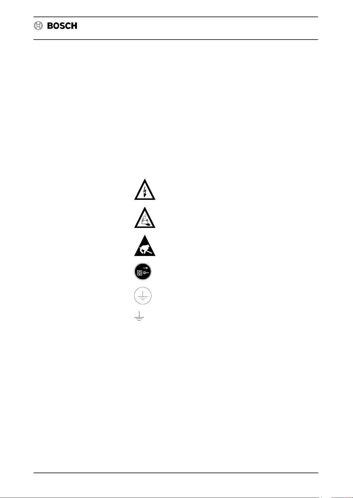
The following warnings and notices may be indicated on the control
components themselves and have the following meaning:
CC 10
Inerface conditions
Danger: High voltage!
Danger: Battery acid!
Electrostatically-sensitive components!
Disconnect at mains before opening!
Pin for connecting PE conductor only!
For screened conductor only!
II
Page 5
Flexible Automation
Safety instructions in this manual
!
DANGER
.
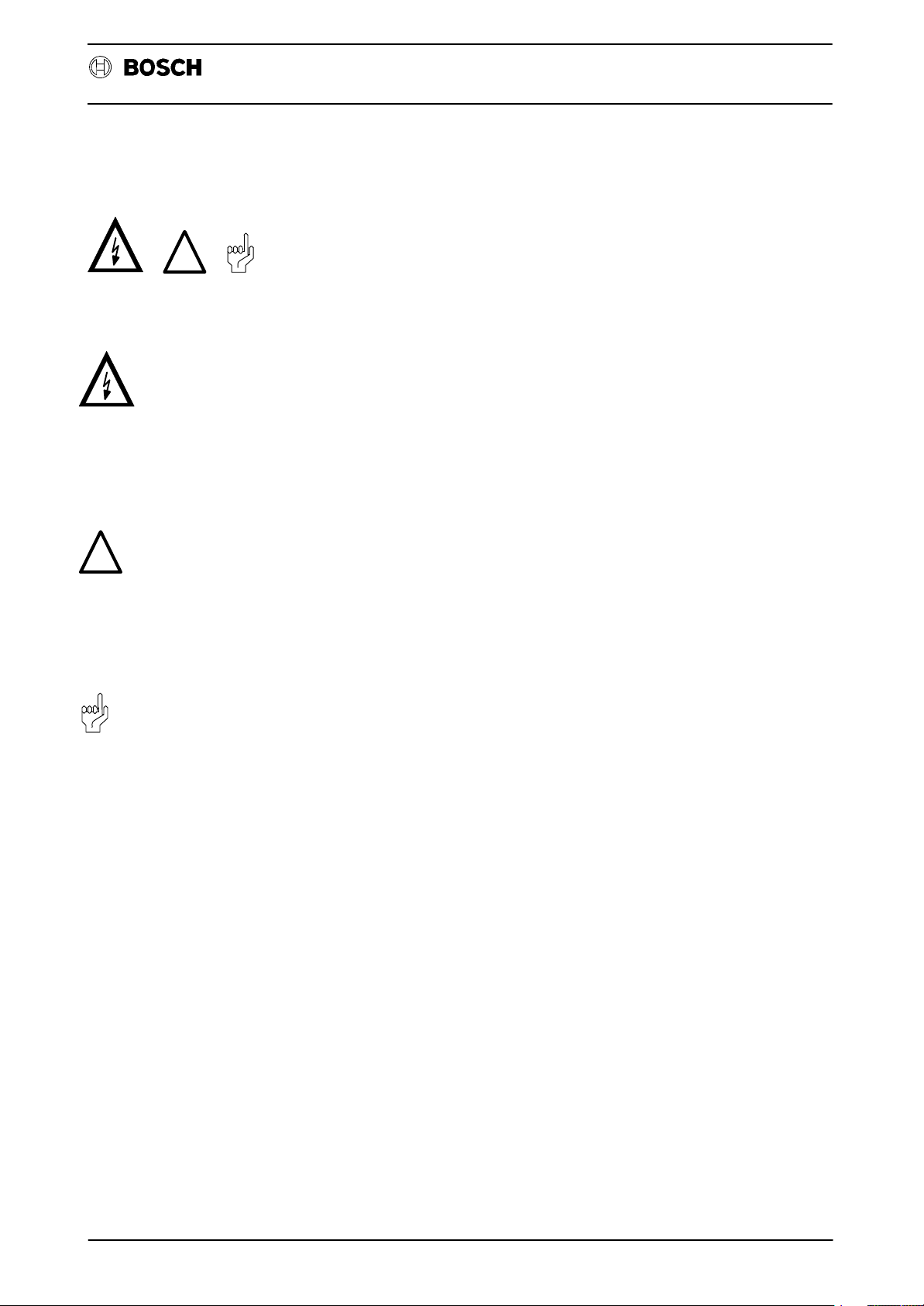
These symbols are used throughout this manual subject to the following
conditions.
This symbol is used to warn of the presence of dangerous electrical
current. Insufficient or lacking compliance with these instructions can
result in personal injury.
Safety instructions accompanied by this symbol are serially numbered,
for example 0.1. The appendix provides translations of the safety notes
shown here in all the official EC languages.
General
CC 10
Inerface conditions
!
.
DANGER
This symbol is used wherever an insufficient or lacking compliance with
instructions can result in personal injury.
Safety instructions accompanied by this symbol are serially numbered,
for example 0.1. The appendix provides translations of the safety notes
shown here in all the official EC languages.
CAUTION
This symbol is used wherever an insufficient or lacking compliance with
instructions can result in damage to equipment or files.
Safety instructions accompanied by this symbol are serially numbered,
for example 0.1. The appendix provides translations of the safety notes
shown here in all the official EC languages.
This symbol is used to inform the user of special features.
III
Page 6

Flexible Automation
Safety instructions
DANGER 0.1
!
CAUTION 0.2
CAUTION 0.3
General
Danger to persons and equipment!
Test every new program before operating the system!
Danger to the module!
Do not insert or remove the module when the control is switched on!
This can destroy the module. Switch off or remove the power supply
module of the control, external power supply and signal voltage be
fore inserting or removing the module!
Danger to the module!
All ESD protection measures must be observed when using the mo
dule! Avoid electrostatic discharges!
Inerface conditions
CC 10
Observe the following protective measures for electrostatically endan
gered modules (EEM)!
D The employees responsible for the storage, transport and handl
ing must be trained in ESD protection.
D EEMs must be stored and transported in the protective packaging
specified.
D EEMs may basically only be handled at special ESD work places
set up specifically for this purpose.
D Employees, work surfaces and all devices and tools, which could
come into contact with EEMs must be same potential (e.g.
earthed).
D Wear an approved earthing strap around your wrist. The ground
ing bracelet must be connected via a cable with integrated 1 M7
resistance with the work surface.
D EEMs may on no account come into contact with chargeable
objects, these include most plastics.
D When inserting EEMs into devices and removing them, the power
source of the device must be switched off.
IV
Page 7

Flexible Automation
Contents
Operating instructions
Contents
Operating instructions
GENERAL 1–1. . . . . . . . . . . . . . . . . . . . . . . . . . . . . . . . . . . . . . . . . . . . . . . . . . . . . . . . . . . . . .
FOREWORD 2–1. . . . . . . . . . . . . . . . . . . . . . . . . . . . . . . . . . . . . . . . . . . . . . . . . . . . . . . . . . . .
Abbreviations 2–4. . . . . . . . . . . . . . . . . . . . . . . . . . . . . . . . . . . . . . . . . . . . . . . . . . . . . . . . . . . . . . . . . . . . . . . . . . .
Device description and information for the user 2–5. . . . . . . . . . . . . . . . . . . . . . . . . . . . . . . . . . . . . . . . . . . . . .
Operating and programming panel BPF 10/BPF 10 E 2–5. . . . . . . . . . . . . . . . . . . . . . . . . . . . . . . . . . . . . . . .
BPF 10 E/built–in version. 2–7. . . . . . . . . . . . . . . . . . . . . . . . . . . . . . . . . . . . . . . . . . . . . . . . . . . . . . . . . . . . . . . .
Display unit 2–9. . . . . . . . . . . . . . . . . . . . . . . . . . . . . . . . . . . . . . . . . . . . . . . . . . . . . . . . . . . . . . . . . . . . . . . . . . . . .
OPERATING ELEMENTS OF THE BPF 10 (E) 2–10. . . . . . . . . . . . . . . . . . . . . . . . . . . . . . . . . . . . . . . . . . . . . .
Function keys 2–11. . . . . . . . . . . . . . . . . . . . . . . . . . . . . . . . . . . . . . . . . . . . . . . . . . . . . . . . . . . . . . . . . . . . . . . . . . .
Decimal point 2–12. . . . . . . . . . . . . . . . . . . . . . . . . . . . . . . . . . . . . . . . . . . . . . . . . . . . . . . . . . . . . . . . . . . . . . . . . . .
NOTES 2–13. . . . . . . . . . . . . . . . . . . . . . . . . . . . . . . . . . . . . . . . . . . . . . . . . . . . . . . . . . . . . . . . . . . . . . . . . . . . . . . .
CONVENTIONS 2–14. . . . . . . . . . . . . . . . . . . . . . . . . . . . . . . . . . . . . . . . . . . . . . . . . . . . . . . . . . . . . . . . . . . . . . . .
Starting level 2–15. . . . . . . . . . . . . . . . . . . . . . . . . . . . . . . . . . . . . . . . . . . . . . . . . . . . . . . . . . . . . . . . . . . . . . . . . . . .
CC 10
FUNCTION BLOCK NO.X (Axis selection) 3–1. . . . . . . . . . . . . . . . . . . . . . . . . . . . . . . . .
FUNCTION BLOCK MODE 4–1. . . . . . . . . . . . . . . . . . . . . . . . . . . . . . . . . . . . . . . . . . . . . . .
FUNCTION: MACHine 4–2. . . . . . . . . . . . . . . . . . . . . . . . . . . . . . . . . . . . . . . . . . . . . . . . . . . . . . . . . . . . . . . . . . .
Function: PROGram execution 4–2. . . . . . . . . . . . . . . . . . . . . . . . . . . . . . . . . . . . . . . . . . . . . . . . . . . . . . . . . . . .
MODE: Approach REFerence points
(applies only in conjunction with incremental measuring system) 4–3. . . . . . . . . . . . . . . . . . . . . . . . . . . . . . .
MODE: MANual axis displacement 4–5. . . . . . . . . . . . . . . . . . . . . . . . . . . . . . . . . . . . . . . . . . . . . . . . . . . . . . . .
TEST part program 4–6. . . . . . . . . . . . . . . . . . . . . . . . . . . . . . . . . . . . . . . . . . . . . . . . . . . . . . . . . . . . . . . . . . . . . .
MODE: AUTOmatic part program execution 4–7. . . . . . . . . . . . . . . . . . . . . . . . . . . . . . . . . . . . . . . . . . . . . . . . .
MODE: SEMI–automatic part program execution 4–7. . . . . . . . . . . . . . . . . . . . . . . . . . . . . . . . . . . . . . . . . . . .
NOTES 4–8. . . . . . . . . . . . . . . . . . . . . . . . . . . . . . . . . . . . . . . . . . . . . . . . . . . . . . . . . . . . . . . . . . . . . . . . . . . . . . . .
FUNCTION BLOCK MEM (Memory) 5–1. . . . . . . . . . . . . . . . . . . . . . . . . . . . . . . . . . . . . . . . . . . . . . . . . . . . . . .
Notes: 5–5. . . . . . . . . . . . . . . . . . . . . . . . . . . . . . . . . . . . . . . . . . . . . . . . . . . . . . . . . . . . . . . . . . . . . . . . . . . . . . . . .
Delete a program 5–8. . . . . . . . . . . . . . . . . . . . . . . . . . . . . . . . . . . . . . . . . . . . . . . . . . . . . . . . . . . . . . . . . . . . . . . .
Rename a program 5–10. . . . . . . . . . . . . . . . . . . . . . . . . . . . . . . . . . . . . . . . . . . . . . . . . . . . . . . . . . . . . . . . . . . . . .
COMPENSATION 5–1 1. . . . . . . . . . . . . . . . . . . . . . . . . . . . . . . . . . . . . . . . . . . . . . . . . . . . . . . . . . . . . . . . . . . . . . .
Tool length compensation 5–11. . . . . . . . . . . . . . . . . . . . . . . . . . . . . . . . . . . . . . . . . . . . . . . . . . . . . . . . . . . . . . . . .
Zero shift 5–15. . . . . . . . . . . . . . . . . . . . . . . . . . . . . . . . . . . . . . . . . . . . . . . . . . . . . . . . . . . . . . . . . . . . . . . . . . . . . . .
Machine parameter program (MPP) 5–18. . . . . . . . . . . . . . . . . . . . . . . . . . . . . . . . . . . . . . . . . . . . . . . . . . . . . . . .
Data input and output 5–21. . . . . . . . . . . . . . . . . . . . . . . . . . . . . . . . . . . . . . . . . . . . . . . . . . . . . . . . . . . . . . . . . . . .
XTRANS 5–24. . . . . . . . . . . . . . . . . . . . . . . . . . . . . . . . . . . . . . . . . . . . . . . . . . . . . . . . . . . . . . . . . . . . . . . . . . . . . . .
Reading in data 5–25. . . . . . . . . . . . . . . . . . . . . . . . . . . . . . . . . . . . . . . . . . . . . . . . . . . . . . . . . . . . . . . . . . . . . . . . .
Reading in part programs 5–26. . . . . . . . . . . . . . . . . . . . . . . . . . . . . . . . . . . . . . . . . . . . . . . . . . . . . . . . . . . . . . . . .
Data output 5–28. . . . . . . . . . . . . . . . . . . . . . . . . . . . . . . . . . . . . . . . . . . . . . . . . . . . . . . . . . . . . . . . . . . . . . . . . . . . .
Contents - 1
Page 8

Flexible Automation
Contents
Operating instructions
FUNCTION BLOCK INFO (Information)
Axis display 6–1. . . . . . . . . . . . . . . . . . . . . . . . . . . . . . . . . . . . . . . . . . . . . . . . . . . . . . . . . . . . . . . . . . . . . . . . . . . . .
Status display 6–3. . . . . . . . . . . . . . . . . . . . . . . . . . . . . . . . . . . . . . . . . . . . . . . . . . . . . . . . . . . . . . . . . . . . . . . . . . .
Error display 6–3. . . . . . . . . . . . . . . . . . . . . . . . . . . . . . . . . . . . . . . . . . . . . . . . . . . . . . . . . . . . . . . . . . . . . . . . . . . .
Software version 6–4. . . . . . . . . . . . . . . . . . . . . . . . . . . . . . . . . . . . . . . . . . . . . . . . . . . . . . . . . . . . . . . . . . . . . . . .
Display of control conditions 6–4. . . . . . . . . . . . . . . . . . . . . . . . . . . . . . . . . . . . . . . . . . . . . . . . . . . . . . . . . . . . . .
Display of inputs and outputs 6–5. . . . . . . . . . . . . . . . . . . . . . . . . . . . . . . . . . . . . . . . . . . . . . . . . . . . . . . . . . . . .
Softkey trees 7 – 1. . . . . . . . . . . . . . . . . . . . . . . . . . . . . . . . . . . . . . . . . . . . . . . . . . . . . . . . . . .
SIGNIFICANCE OF THE SOFTKEYS 7 – 4. . . . . . . . . . . . . . . . . . . . . . . . . . . . . . . . . . . . . . . . . . . . . . . . . . . . . .
Error codes 8–1. . . . . . . . . . . . . . . . . . . . . . . . . . . . . . . . . . . . . . . . . . . . . . . . . . . . . . . . . . . . .
CC 10 module
CC 10
Control versions for driving 1 axis, incremental measuring system 9–1. . . . . . . . . . . . . . . . . . . . . . . . . . . . . .
Control versions for driving 1–3 axes, incremental measuring system 9–2. . . . . . . . . . . . . . . . . . . . . . . . . . .
Control versions for driving 1–3 axes, absolute measuring system 9–3. . . . . . . . . . . . . . . . . . . . . . . . . . . . .
Data transfer CC 10.3 $ PG6 9–4. . . . . . . . . . . . . . . . . . . . . . . . . . . . . . . . . . . . . . . . . . . . . . . . . . . . . . . . . . . . .
Loading new operating software 9–4. . . . . . . . . . . . . . . . . . . . . . . . . . . . . . . . . . . . . . . . . . . . . . . . . . . . . . . . . . .
Initializing the FLASH EPROM 9–5. . . . . . . . . . . . . . . . . . . . . . . . . . . . . . . . . . . . . . . . . . . . . . . . . . . . . . . . . . . .
Contents - 2
Page 9

Flexible Automation
Contents
Programming instructions
Contents
Programming instructions
General
Program creation 10–1. . . . . . . . . . . . . . . . . . . . . . . . . . . . . . . . . . . . . . . . . . . . . . . . . . . . . . . . . . . . . . . . . . . . . . . .
Reading data in/out 10–1. . . . . . . . . . . . . . . . . . . . . . . . . . . . . . . . . . . . . . . . . . . . . . . . . . . . . . . . . . . . . . . . . . . . . .
Editing programs 10–1. . . . . . . . . . . . . . . . . . . . . . . . . . . . . . . . . . . . . . . . . . . . . . . . . . . . . . . . . . . . . . . . . . . . . . . .
Program execution 10–1. . . . . . . . . . . . . . . . . . . . . . . . . . . . . . . . . . . . . . . . . . . . . . . . . . . . . . . . . . . . . . . . . . . . . .
Part programs 10–1. . . . . . . . . . . . . . . . . . . . . . . . . . . . . . . . . . . . . . . . . . . . . . . . . . . . . . . . . . . . . . . . . . . . . . . . . .
Memory allocation 10–2. . . . . . . . . . . . . . . . . . . . . . . . . . . . . . . . . . . . . . . . . . . . . . . . . . . . . . . . . . . . . . . . . . . . . . .
Start of program 10–2. . . . . . . . . . . . . . . . . . . . . . . . . . . . . . . . . . . . . . . . . . . . . . . . . . . . . . . . . . . . . . . . . . . . . . . . .
Program run 10–2. . . . . . . . . . . . . . . . . . . . . . . . . . . . . . . . . . . . . . . . . . . . . . . . . . . . . . . . . . . . . . . . . . . . . . . . . . . .
Program end 10–2. . . . . . . . . . . . . . . . . . . . . . . . . . . . . . . . . . . . . . . . . . . . . . . . . . . . . . . . . . . . . . . . . . . . . . . . . . . .
Program block 10–2. . . . . . . . . . . . . . . . . . . . . . . . . . . . . . . . . . . . . . . . . . . . . . . . . . . . . . . . . . . . . . . . . . . . . . . . . .
Program word 10–3. . . . . . . . . . . . . . . . . . . . . . . . . . . . . . . . . . . . . . . . . . . . . . . . . . . . . . . . . . . . . . . . . . . . . . . . . . .
Block number 10–3. . . . . . . . . . . . . . . . . . . . . . . . . . . . . . . . . . . . . . . . . . . . . . . . . . . . . . . . . . . . . . . . . . . . . . . . . . .
Program format 10–4. . . . . . . . . . . . . . . . . . . . . . . . . . . . . . . . . . . . . . . . . . . . . . . . . . . . . . . . . . . . . . . . . . . . . . . . .
CC 10
G–FUNCTIONS 1 1–1. . . . . . . . . . . . . . . . . . . . . . . . . . . . . . . . . . . . . . . . . . . . . . . . . . . . . . . . . .
Positioning in rapid traverse mode 11–2. . . . . . . . . . . . . . . . . . . . . . . . . . . . . . . . . . . . . . . . . . . . . . . . . . . . . . . . .
Linear interpolation in feed mode 11–3. . . . . . . . . . . . . . . . . . . . . . . . . . . . . . . . . . . . . . . . . . . . . . . . . . . . . . . . . .
Circular interpolation 11–5. . . . . . . . . . . . . . . . . . . . . . . . . . . . . . . . . . . . . . . . . . . . . . . . . . . . . . . . . . . . . . . . . . . .
Helical interpolation 11–9. . . . . . . . . . . . . . . . . . . . . . . . . . . . . . . . . . . . . . . . . . . . . . . . . . . . . . . . . . . . . . . . . . . . . .
Dwell time 11–10. . . . . . . . . . . . . . . . . . . . . . . . . . . . . . . . . . . . . . . . . . . . . . . . . . . . . . . . . . . . . . . . . . . . . . . . . . . . . .
Programmed acceleration ON/OFF 11–11. . . . . . . . . . . . . . . . . . . . . . . . . . . . . . . . . . . . . . . . . . . . . . . . . . . . . . . .
Plane selection 11–12. . . . . . . . . . . . . . . . . . . . . . . . . . . . . . . . . . . . . . . . . . . . . . . . . . . . . . . . . . . . . . . . . . . . . . . . . .
Conditional/unconditional jump 11–13. . . . . . . . . . . . . . . . . . . . . . . . . . . . . . . . . . . . . . . . . . . . . . . . . . . . . . . . . . . .
Zero shifts 11–15. . . . . . . . . . . . . . . . . . . . . . . . . . . . . . . . . . . . . . . . . . . . . . . . . . . . . . . . . . . . . . . . . . . . . . . . . . . . . .
Exact positioning ON/OFF 11–17. . . . . . . . . . . . . . . . . . . . . . . . . . . . . . . . . . . . . . . . . . . . . . . . . . . . . . . . . . . . . . . .
Set 100 % feedrate 11–18. . . . . . . . . . . . . . . . . . . . . . . . . . . . . . . . . . . . . . . . . . . . . . . . . . . . . . . . . . . . . . . . . . . . .
Clear G63 11–18. . . . . . . . . . . . . . . . . . . . . . . . . . . . . . . . . . . . . . . . . . . . . . . . . . . . . . . . . . . . . . . . . . . . . . . . . . . . . .
Automatic approach to reference point 11–19. . . . . . . . . . . . . . . . . . . . . . . . . . . . . . . . . . . . . . . . . . . . . . . . . . . . .
Absolute dimension input 11–21. . . . . . . . . . . . . . . . . . . . . . . . . . . . . . . . . . . . . . . . . . . . . . . . . . . . . . . . . . . . . . . . .
Incremental dimension input 11–21. . . . . . . . . . . . . . . . . . . . . . . . . . . . . . . . . . . . . . . . . . . . . . . . . . . . . . . . . . . . . .
Miscellaneous functions 12–1. . . . . . . . . . . . . . . . . . . . . . . . . . . . . . . . . . . . . . . . . . . . . . . . .
Auxiliary functions 12–4. . . . . . . . . . . . . . . . . . . . . . . . . . . . . . . . . . . . . . . . . . . . . . . . . . . . . . . . . . . . . . . . . . . . . . .
General 12–4. . . . . . . . . . . . . . . . . . . . . . . . . . . . . . . . . . . . . . . . . . . . . . . . . . . . . . . . . . . . . . . . . . . . . . . . . . . . . . . .
Function 12–4. . . . . . . . . . . . . . . . . . . . . . . . . . . . . . . . . . . . . . . . . . . . . . . . . . . . . . . . . . . . . . . . . . . . . . . . . . . . . . .
(Program stop, program end) 12–5. . . . . . . . . . . . . . . . . . . . . . . . . . . . . . . . . . . . . . . . . . . . . . . . . . . . . . . . . . . . .
Block preparation 12–6. . . . . . . . . . . . . . . . . . . . . . . . . . . . . . . . . . . . . . . . . . . . . . . . . . . . . . . . . . . . . . . . . . . . . . . .
Function of the WAIT command 12–6. . . . . . . . . . . . . . . . . . . . . . . . . . . . . . . . . . . . . . . . . . . . . . . . . . . . . . . . . . .
Read monitoring E–code 12–7. . . . . . . . . . . . . . . . . . . . . . . . . . . . . . . . . . . . . . . . . . . . . . . . . . . . . . . . . . . . . . . . .
Contents - 3
Page 10

Flexible Automation
Contents
Programming instructions
Compensation tables
Tool length compensation ”Hxx” 13–1. . . . . . . . . . . . . . . . . . . . . . . . . . . . . . . . . . . . . . . . . . . . . . . . . . . . . . . . . . .
Zero shifts ”Gxx” 13–3. . . . . . . . . . . . . . . . . . . . . . . . . . . . . . . . . . . . . . . . . . . . . . . . . . . . . . . . . . . . . . . . . . . . . . . .
Zero shift in conjunction with rotary axes 13–4. . . . . . . . . . . . . . . . . . . . . . . . . . . . . . . . . . . . . . . . . . . . . . . . . . .
Reading in the tables 13–5. . . . . . . . . . . . . . . . . . . . . . . . . . . . . . . . . . . . . . . . . . . . . . . . . . . . . . . . . . . . . . . . . . . .
Saving the tables in the FLASH EPROM 13–5. . . . . . . . . . . . . . . . . . . . . . . . . . . . . . . . . . . . . . . . . . . . . . . . . . .
Programming the rotary axis
Displacement input 14–1. . . . . . . . . . . . . . . . . . . . . . . . . . . . . . . . . . . . . . . . . . . . . . . . . . . . . . . . . . . . . . . . . . . . . .
CC 10
Contents - 4
Page 11

Flexible Automation
Contents
Remote control
Contents
Remote control
General 15–1. . . . . . . . . . . . . . . . . . . . . . . . . . . . . . . . . . . . . . . . . . . . . . . . . . . . . . . . . . . . . . .
Machine parameters 16–1. . . . . . . . . . . . . . . . . . . . . . . . . . . . . . . . . . . . . . . . . . . . . . . . . . . . .
Interface selection 17–1. . . . . . . . . . . . . . . . . . . . . . . . . . . . . . . . . . . . . . . . . . . . . . . . . . . . . .
Interface selection via PLC interface 17–2. . . . . . . . . . . . . . . . . . . . . . . . . . . . . . . . . . . . . . . . . . . . . . . . . . . . . . .
REQUIRED DATA CHANNEL 18 – 1. . . . . . . . . . . . . . . . . . . . . . . . . . . . . . . . . . . . . . . . . . . . .
Handshake mode 18 – 2. . . . . . . . . . . . . . . . . . . . . . . . . . . . . . . . . . . . . . . . . . . . . . . . . . . . . . . . . . . . . . . . . . . . . . .
CC10.3 receives required data 18 – 2. . . . . . . . . . . . . . . . . . . . . . . . . . . . . . . . . . . . . . . . . . . . . . . . . . . . . . . . . . . .
CC10.3 transmits required data 18 – 3. . . . . . . . . . . . . . . . . . . . . . . . . . . . . . . . . . . . . . . . . . . . . . . . . . . . . . . . . . .
CC 10
Functions 19–1. . . . . . . . . . . . . . . . . . . . . . . . . . . . . . . . . . . . . . . . . . . . . . . . . . . . . . . . . . . . . .
Read–in 19–2. . . . . . . . . . . . . . . . . . . . . . . . . . . . . . . . . . . . . . . . . . . . . . . . . . . . . . . . . . . . . . . . . . . . . . . . . . . . . . . .
Read–in of part programs 19–2. . . . . . . . . . . . . . . . . . . . . . . . . . . . . . . . . . . . . . . . . . . . . . . . . . . . . . . . . . . . . . . .
Read–in of compensation tables 19–3. . . . . . . . . . . . . . . . . . . . . . . . . . . . . . . . . . . . . . . . . . . . . . . . . . . . . . . . . . .
Read–in of zero shifts 19–4. . . . . . . . . . . . . . . . . . . . . . . . . . . . . . . . . . . . . . . . . . . . . . . . . . . . . . . . . . . . . . . . . . . .
Read–in of machine parameters 19–5. . . . . . . . . . . . . . . . . . . . . . . . . . . . . . . . . . . . . . . . . . . . . . . . . . . . . . . . . . .
Read–out 19–6. . . . . . . . . . . . . . . . . . . . . . . . . . . . . . . . . . . . . . . . . . . . . . . . . . . . . . . . . . . . . . . . . . . . . . . . . . . . . .
Requesting a part program 19–6. . . . . . . . . . . . . . . . . . . . . . . . . . . . . . . . . . . . . . . . . . . . . . . . . . . . . . . . . . . . . . .
Requesting the compensation tables 19–7. . . . . . . . . . . . . . . . . . . . . . . . . . . . . . . . . . . . . . . . . . . . . . . . . . . . . . .
Requesting the zero shift table 19–8. . . . . . . . . . . . . . . . . . . . . . . . . . . . . . . . . . . . . . . . . . . . . . . . . . . . . . . . . . . .
Requesting the machine parameters 19–9. . . . . . . . . . . . . . . . . . . . . . . . . . . . . . . . . . . . . . . . . . . . . . . . . . . . . . .
Deleting files (applicable only to part programs) 19–10. . . . . . . . . . . . . . . . . . . . . . . . . . . . . . . . . . . . . . . . . . . . . .
Determining memory space 19–11. . . . . . . . . . . . . . . . . . . . . . . . . . . . . . . . . . . . . . . . . . . . . . . . . . . . . . . . . . . . . . .
Program directory 19–12. . . . . . . . . . . . . . . . . . . . . . . . . . . . . . . . . . . . . . . . . . . . . . . . . . . . . . . . . . . . . . . . . . . . . . .
Programming files (in the EEPROM) 19–13. . . . . . . . . . . . . . . . . . . . . . . . . . . . . . . . . . . . . . . . . . . . . . . . . . . . . . .
Programming part programs 19–13. . . . . . . . . . . . . . . . . . . . . . . . . . . . . . . . . . . . . . . . . . . . . . . . . . . . . . . . . . . . . .
Programming zero shift tables 19–14. . . . . . . . . . . . . . . . . . . . . . . . . . . . . . . . . . . . . . . . . . . . . . . . . . . . . . . . . . . . .
Programming compensation tables 19–14. . . . . . . . . . . . . . . . . . . . . . . . . . . . . . . . . . . . . . . . . . . . . . . . . . . . . . . .
Programming machine parameters 19–15. . . . . . . . . . . . . . . . . . . . . . . . . . . . . . . . . . . . . . . . . . . . . . . . . . . . . . . .
Read-out of any list of errors present 19–16. . . . . . . . . . . . . . . . . . . . . . . . . . . . . . . . . . . . . . . . . . . . . . . . . . . . . . .
ANNEX
Connection cable PG6 <––> CNC 20–1. . . . . . . . . . . . . . . . . . . . . . . . . . . . . . . . . . . . . . . . . . . . . . . . . . . . . . . . .
Connection via V.24 interface (COM1) 20–1. . . . . . . . . . . . . . . . . . . . . . . . . . . . . . . . . . . . . . . . . . . . . . . . . . . . . .
ASCII character set 20–3. . . . . . . . . . . . . . . . . . . . . . . . . . . . . . . . . . . . . . . . . . . . . . . . . . . . . . . . . . . . . . . . . . . . . .
Contents - 5
Page 12

Flexible Automation
Contents
CC 10
Remote control
Contents - 6
Page 13
Flexible Automation
GENERAL
General
This description refers to the CC 10 operating system software as from version C40.
Operating instructions
CC 10
CC 10
Computer–assisted positioning control for max. 3 axes
These instructions are intended for the user of the CC 10 control system.
1 - 1
Page 14

Flexible Automation
General
CC 10
Operating instructions
1 - 2
Page 15

Flexible Automation
FOREWORD
Introduction
These instructions describe the operator steps which must be performed on the
CNC itself. They apply only to type CC 10 control systems. Only the described sequences and operations are permitted.
Machine–specific operation through assignment of the function keys F1–F12 is described by the machine tool manufacturer.
All function blocks (FBL) are represented in their overall context, together with all
possible operating sequences. This permits a general overview of all the functions
available in a particular FBL and their selection. The ”arrow notation” (softkey
trees) used for this purpose is intended as a simple and effective memory aid for
experienced operators.
The error messages for the CC 10 are contained in Chapter 8. Chapter 9 contains
further details relating to the function descriptions and examples.
Operating instructions
CC 10
These operating instructions represent a control–specific general ”reference work”
giving the user details and comprehensive information on the available functions
and their selection as well as permitting effective operation of the control system.
The CC 10 is a computer–assisted numerical positioning control (CNC) for use in
the following fields:
` special mechanical engineering
` transfer lines
` handling technology
` assembly technology
` feed units and
` auxiliary axes on machine tools.
The CC 10 is integrated in the programmable logic controllers (PLC) CL 300 or PC
600 (refer to the ”Interface conditions”).
The CC 10 has its own microprocessor and a part program memory with a capacity
of 10 kBytes (for max. 99 part programs). This permits axis positioning parallel to
the PLC cycle without affecting the timing of the latter . Position–controlled axes can
be expanded from 1 axis to 3 axes.
2 - 1
Page 16

Flexible Automation
Introduction
Up to 3 axes can be operated
` as asynchronous, mutually independent axes, each with its own part pro-
gram
or
` as synchronous axes with a common part program.
This specification and any adjustment to the machine–specific requirements are
defined by input of machine parameters.
Operator prompts in all modes ensure that the operator makes the necessary sen-
sible inputs. These prompts also allow the operator to jump to different function and
softkey levels in accordance with the type of information and operation required.
Detailed error messages assist the user in the event of any operator errors.
The CC 10 possesses 4 function blocks (FBL) which can be selected by means
S1 S2 S3 S4
Operating instructions
CC 10
of the function keys or softkeys
board on the operating and programming panel (BPF 10):
S1
` NO.X
Chapter 3
(Axis changeover for asynchronous axes)
S2
` MODE
Chapter 4
(Automatic execution and setting–up mode)
S3
` MEMory
Chapter 5
(Storage)
S4
` INFOrmation
Chapter 6
(Diagnosis)
in the top row of the key-
These function blocks are described in the following chapters and explained with
the aid of examples.
2 - 2
Page 17

Flexible Automation
Introduction
Each FBL has a number of function levels, each of which may contain up to 4 different functions.
The level return key is located on the far right in the second line of the key-
board. This key is pressed in order to jump back to the preceding (higher)
function level. In some levels, operation of this key results in a jump back over two
functions levels. The functions of the individual keys are described in the subsection ”OPERATING ELEMENTS”.
The chapter ”INTRODUCTION” briefly describes the
` operating and programming panel BPF 10 and BPF 10 E
` operating elements
Operating instructions
CC 10
` display unit
of the CC 10, as well as general information of relevance for the subsequent chap-
ters.
The user is advised to read the chapter ”INTRODUCTION” and to note the informa-
tion in the subsections ”NOTES” and ”CONVENTIONS” for subsequent operation.
he chapter ”INTRODUCTION” starts with a list of the abbreviations used in these
operating instructions, before going on to describe the operating and programming
panel (BPF 10).
2 - 3
Page 18

Flexible Automation
Abbreviations
Introduction
ASCII ”American standard code for information interchange”
(data transmission code)
BAUD Baud rate or transmission rate in characters per second
BPF Operating and programming panel
CC Computer control
CL Control logic
CNC Computerized numerical control
DCR Digital cassette recorder
DFS Define store program
EPROM Erasable Programmable Read Only Memory
Operating instructions
CC 10
EEPROM Electrically Erasable Programmable Read Only Memory
FLASH-EPROM Side by side electrically deletable and programmable read
memory
FBL Function block
FU Function
I/O Input/Output
kByte Kilo–Byte (1024 bytes)
LED Light–emitting diode
MP Machine parameter
MPP Machine parameter program
NC Numerical control
P Part program
PG6 PG6 programming device
RAM Random Access Memory
SK Softkey
PCMCIA Personal Computer Memory Card International Association
(international association for standardising PC memory cards)
2 - 4
Page 19

Flexible Automation
Introduction
Device description and information for the user
This subsection contains a general description of the operating and programming
panel and the layout of the display . It also explains the significance of the individual
operating elements.
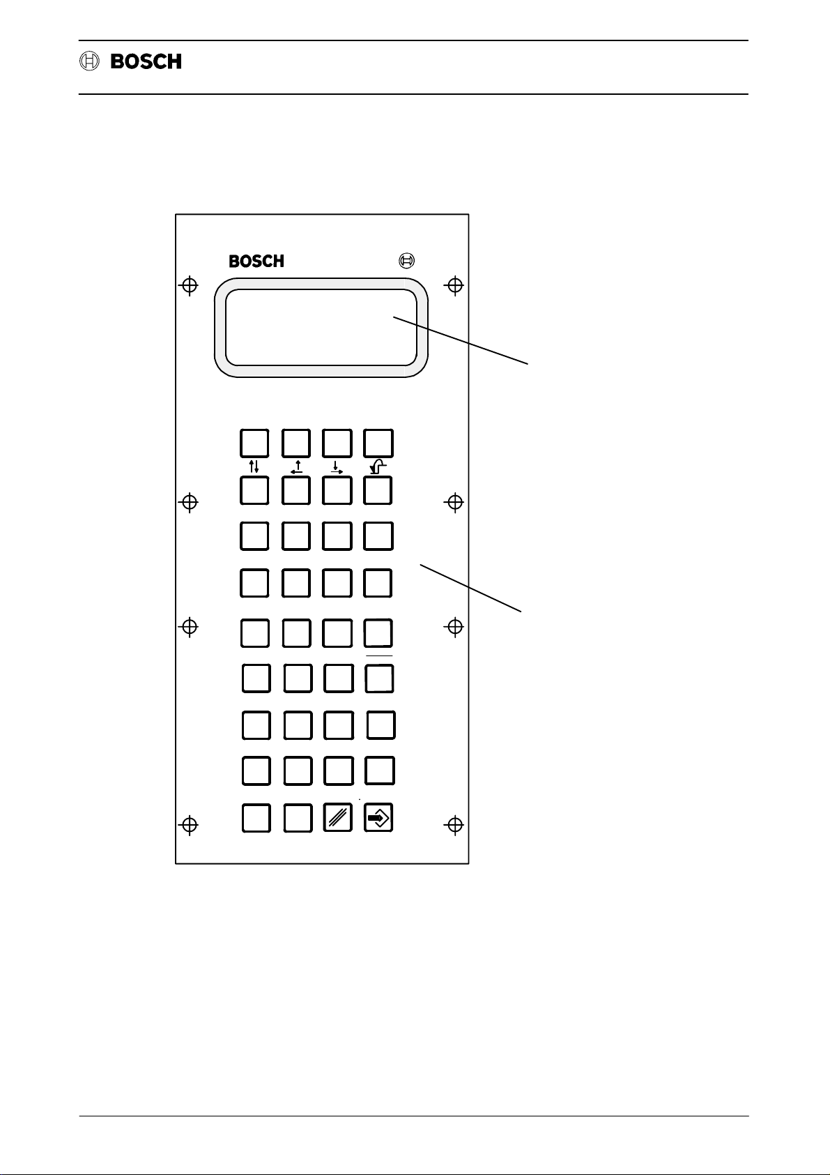
Operating and programming panel BPF 10/BPF 10 E
The operating and programming panel is available in two versions:
` as BPF 10/hand–held unit and
` as BPF 10 E/built–in version.
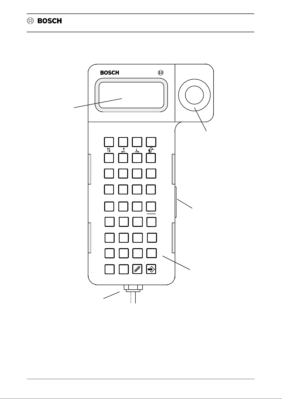
BPF 10 hand–held unit
The BPF 10 hand–held unit is intended for mobile applications. It comprises a
housing accommodating the electronics. The keypad, display unit and EMERGENCY OFF button are located on the front. The BPF 10 is connected to the control system via a cable. The housing is made of black thermoplastic material.
CC 10
Operating instructions
Keypad
Consent key
Display unit
EMERGENCY OFF key
The BPF 10 has a total of 36 keys with different functions (refer to the section OPERATING ELEMENTS of the BPF 10 (E)).
The CONSENT KEY is located on the side panel of the BPF 10. It must be pressed
whenever one of the freely definable function keys F1 – F12 is to be activated. This
key is positioned in such a way that it cannot simply be circumvented (for instance
by jamming the switching element). The contact in the consent key is opened by
spring force.
An LCD display unit (4 x 20 positions) with alphanumeric characters is used as the
display. The character height is approx. 5 mm.
The EMERGENCY OFF key is a slam button with locking switching element and
reliably opening contact. It must be wired to the monitoring circuit of the control cabinet.
2 - 5
Page 20
Flexible Automation
Display unit
Introduction
CC 10
Operating instructions
S1 S2 S3 S4
F1 F2 F3 F4
F5 F6 F7 F8
F9 F10 F11 F12
789
SPACE
456
123
.
0
Shift
EMERGENCY OFF key
+
Consent key
Key field
Cable connection
2 - 6
Page 21

Flexible Automation
BPF 10 E/built–in version.
Keypad
Display unit
Introduction
The built–in unit is designed for installation in panel cut–outs (e.g. control cabinet
door or operating panel). It consists of a scaled panel to which the electronics of
the BPF 10 is secured.
The unit does not possess either an EMERGENCY OFF button or a consent key .
Otherwise, it is identical with the hand–held unit.
The keypad for the BPF 10 built–in unit is identical with that of the hand–held BPF
10. Refer to the description of the keypad for the BPF 10 hand–held unit for further
details.
A 4 x 20–position LCD display unit with alphanumeric characters is used for display
purposes. All ASCII characters can be represented. The character height is
approx. 5 mm.
Operating instructions
CC 10
2 - 7
Page 22
Flexible Automation
Introduction
S1 S2 S3 S4
CC 10
Operating instructions
Display
F1 F2 F3 F4
F5 F6 F7 F8
F9 F10 F11 F12
789
SPACE
456
123
.
0
Shift
Key field
+
2 - 8
Page 23
Flexible Automation
Display unit
Introduction
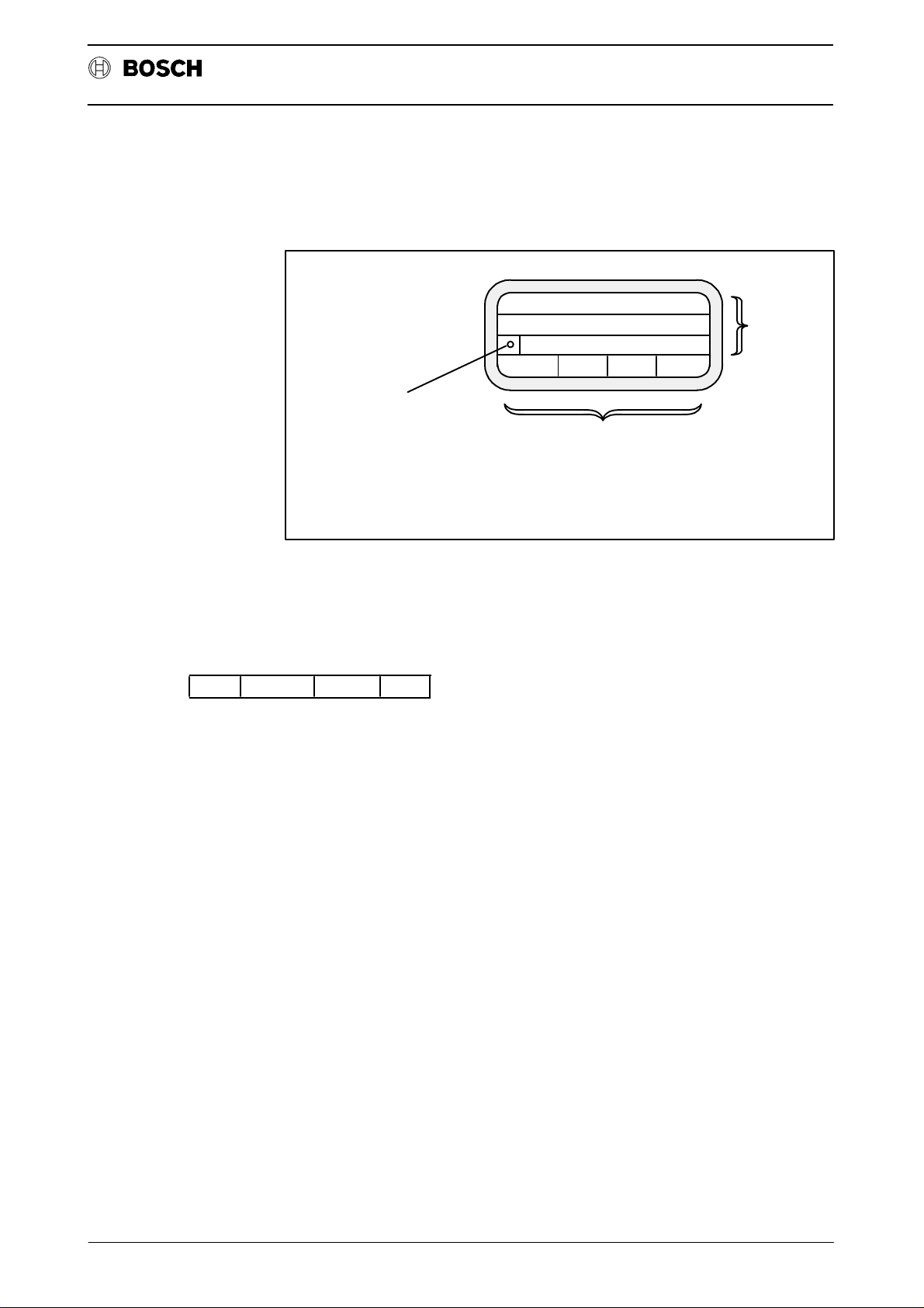
The typical display unit layout for the CC 10 is shown in the figure below:
Error display
Operating instructions
Text lines
and
information
CC 10
(A "Question mark" is shown
in this field if an error occurs.
A plain-text description of
the error is then contained
in the FBL INFO.)
The display consists of a 4 x 20–position display unit with alphanumeric characters.
The character height is approx. 5 mm. When the control system is switched on (refer to the starting display), the available function blocks ”NO.X, MODE, MEM and
INFO” are displayed in the bottom line. The function blocks (FBL) are activated by
pressing softkeys S1–S4:
NO.X MODE MEM INFO
NO.X: Axis changeover
MODE: MODE (automatic/setting–up)
MEM: MEMory (storage)
INFO: INFOrmation (diagnosis)
Function key or softkey
window (changing
significance)
2 - 9
Page 24

Flexible Automation
Introduction
OPERATING ELEMENTS OF THE BPF 10 (E)
Softkeys
S1 S2 S3 S4
These keys are used to call up the individual function blocks:
S1: NO.X (axis selection)
S2: MODE
S3: MEMory
S4: INFOrmation
Cursor keys
CC 10
Operating instructions
Individual function:
The cursor can be moved to the left and right or up and down on the display unit
pressing these cursor keys.
The keys can be used in the program editor and for paging through the program
directory.
Programs and tables can be edited at the point at which the cursor is located.
Double function:
The cursor automatically jumps to the beginning of the preceding line when these
two cursor keys are pressed simultaneously.
Level return key:
The cursor jumps to the start of the next line when these two keys are pressed simultaneously .
By pressing the level return key, it is possible to jump back from one function level
to the previous (next higher) level or all the way back to the starting level.
2 - 10
Page 25
Flexible Automation
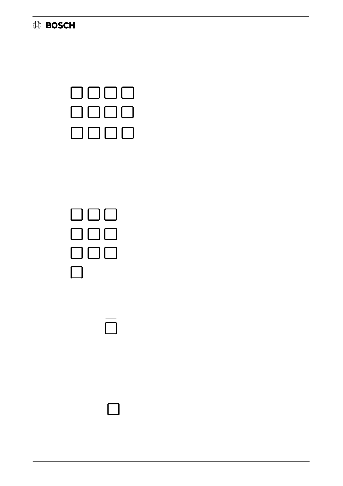
Function keys
F1 F2 F3 F4
F5 F6 F7 F8
F9 F10 F11 F12
The function keys F1 – F12 can be freely defined via the MPP and do not have any
predetermined functions.
Note:
No signals affecting safety such as ”STOP” or ”START” must be routed via these
keys.
Introduction
CC 10
Operating instructions
Number keys
Minus sign –
Plus sign +
789
456
123
0
Numbers 0 – 9
+
If the value of an input is negative, a negative sign must be written between the
address letter and the string of digits.
SPACE
Positive signs may be written but need not be.
SPACE
Space between words
2 - 11
Page 26

Flexible Automation
Decimal point
Delete key
SHIFT key
Introduction
.
Shift
Shift for keys with two functions in the program editor.
Pressed: Lower character active.
Released: Upper character active
CC 10
Operating instructions
ENTER key
Confirms and stores the input.
2 - 12
Page 27

Flexible Automation
NOTES
Introduction
This section contains general operating instructions which apply to the subsequent
chapters. No further reference will be made there to the specific significance of the
points listed below.
` Fixed functions are assigned to softkeys on all levels.
` Each FBL has a number of function or softkey levels which can be selected
in succession. The next following (lower) function level is activated when-
ever the corresponding function keys S1–S4 are pressed.
` Each new key assignment is designated as a softkey or function level.
` Each numerical value input must be confirmed by pressing the key .
Operating instructions
CC 10
` The level return key can be used to jump back to the preceding
(higher) level.
` In order to select a different FBL, it is necessary to jump back to the starting
level by pressing .
` When the control system is switched on, the reference points must first be
approached in order to permit execution of a program (exception: the func-
tion ”Approach reference point” is not included in absolute measuring sys-
tems).
` There is a switch on the front panel of the CC 10 module (refer to the chapter
EXPLANATIONS) which allows the EEPROM write protection to be
switched on and off.
` The machine control panel is provided by the machine tool manufacturer.
Operations associated with the machine control panel are therefore not ex-
plicitly described here.
2 - 13
Page 28

Flexible Automation
CONVENTIONS
Introduction
Press the function key
Enter numerical values
Confirm input of numerical values
Return to the next higher level
The following program example (P12) is always used for reference in the subsequent chapters.
N10X01=100G62
Operating instructions
CC 10
N20X02=200
N30X03=300
N40X01=0X02=0X03=0
N50M30
Significance:
Axes X01 – X03 are traversed to the SETPOINT positions 100 mm, 200 mm and
300 mm block–by–block (SEMI) or automatically (AUTO) in the function ”Execute
PROGram” (refer to FBL ”MODE”). All axes are then traversed to position ”0”.
2 - 14
Page 29

Flexible Automation
Starting level
Introduction
The CC 10 performs a self–test when the control system is switched on. When this
self–test has been completed successfully, the control system is in the starting
level and shows the following typical display for the CC 10:
Operating instructions
CC 10
Significance
of the functions
CC10 VERSION C20
SW-V: 63969.101
NO.X MODE MEM INFO
The version number refers to the operating system software and has the following
significance:
I
C40I
alphanumeric code for an existing
for CC 10
Development stage,
here: stage 4
N0.X: FBL AXIS SELECTION
Selection of asynchronous axes.
MODE: FBL MODE
version (internal Bosch code)
Maintenance version of a development
stage 0 = no maintenance version.
` MANUAL (setting–up)
` APPROACH REFERENCE POINT(S)
` SEMI–AUTOMATIC
` AUTOMATIC
` HAND
` TEST
MEM: FBL MEMORY (storage)
` Display, edit and store
part programs,
tool compensation values,
zero shifts,
machine parameters.
` Data input and output from/to external data media.
2 - 15
Page 30

Flexible Automation
Introduction
INFO: FBL INFORMATION (diagnosis)
` Display of
ACTUAL and SETPOINT locations,
difference between SETPOINT and ACTUAL positions,
lag, status (error display, condition, reset) as well as
input and output signals (digital interface CC 10 $ PLC).
` Trip to basic setting (Reset)
The respective FBL can be selected by pressing the softkeys S1 – S4 when the
starting display appears after the self–test. The functions which can be activated
in these FBL are described in the following chapters together with their significance.
Operating instructions
CC 10
2 - 16
Page 31

Flexible Automation
FBL NO.X (axis selection)
FUNCTION BLOCK NO.X (Axis selection)
Softkey S1 ”NO.X” is used to select asynchronous axes (max. 3 axes, e.g. X01 –
X03) if these have been defined in the machine parameter program. The first axis
is activated after switching on. Since each asynchronous axis has its own part program, each axis is controlled separately, i.e. a separate part program is executed
for each asynchronous axis.
Only synchronous axes can be selected if asynchronous axes have not been defined in the MPP. The following message is displayed if softkey ”NO.X” is pressed
nevertheless:
SYNCHRONOUS-AXIS
NO.X MODE MEM INFO
CC 10
Operating instructions
This indicates that only synchronous axes have been defined and that asynchronous axes cannot be selected.
3 - 1
Page 32

Flexible Automation
FBL NO.X (axis selection)
CC 10
Operating instructions
3 - 2
Page 33

Flexible Automation
FUNCTION BLOCK MODE
The modes can be selected via the interface inputs I1.0...1.2 (refer to the description of the digital interface in the ”Interface conditions”) or via the
NO.X MODE MEM INFO
The first menu level reached after pressing the softkey ”MODE” contains the two
function groups
` PROGram execution and
` MACHINE:
FBL Mode
CC 10
Operating instructions
The modes available in FBL ”MODE” are selected by pressing ”PROG” or
”MACH”.
PROG MASCH
4 - 1
Page 34

Flexible Automation
FUNCTION: MACHine
FBL Mode
The following modes can be called up when ”MACH” is pressed:
.
.
PROG MASCH
MANUAL MODE
REF MAN
Significance of these modes:
` REF: Approach REFerence point(s)
Operating instructions
CC 10
` MAN: MANual displacement of the axes (e.g. by means ofthe jog
Function: PROGram execution
The following modes can be selected by pressing ”PROG”:
.
.
PROG MASCH
P11 P12
AUTO SEMI TEST
Significance of these modes
` AUTO: AUTOmatic execution of a part program from the first block to
` SEMI: SEMI–automatic (block–by–block) execution of the program
keys on the machine control panel).
the end of the program.
by pressing the ST ART key on the machine tool control panel.
` TEST : Program check for SYNTAX errors.
4 - 2
Page 35

Flexible Automation
FBL Mode
MODE: Approach REFerence points
(applies only in conjunction with incremental measuring system)
The mode ”Approach reference point” (refer to the Interface conditions, Chapter
6 ”Digital interface”) is output at the digital interface outputs (CC 10 ! PLC) when
”REF” is pressed. The feedback signal from the corresponding inputs I4.2–I4.4
then allows the corresponding axes to approach the reference points.
The procedure for approaching the reference points is represented with the aid of
the various softkey levels. Selection is made by pressing ”MOD”, ”MACH” and
”REF”:
The starting display with selection menu appears when the control system is
switched on (version may differ, here C20I).
CC 10
Operating instructions
CC10 VERSION C20
SW-V: 63969.101
NO.X MODE MEM INFO
CC10 VERSION C20
SW-V:63969.101
PROG MASCH
Select ”MACH”
MANUAL MODE
REF MAN
Select ”REF” (not applicable in the case of absolute measuring systems)
REF
*POS COM DIST LAG
X01 0.000*
X02 0.000*
X03 0.000*
I
I
The axes can now be travelled to the reference point in accordance with the machine manufacturer’s instructions.
4 - 3
Page 36

Flexible Automation
FBL Mode
When the reference point switches have been reached, the axes are synchronized
with the zero pulse of the measuring system and the limit positions are displayed
for each axis.
Operating instructions
CC 10
REF
*POS COM DIST LAG
These are the coordinate values of the respective reference points as defined in
the MPP.
When an axis (e.g axis 1) approaches the reference point (manual or via G74) and
has synchronized with the zero point, the signal REFERENCE POINT APPROACH AXIS 1 is set in the digital interface (refer to the Interface conditions/Digital interface).
The INPOS signal *" is displayed after the corresponding axis to indicate that the
reference points have been reached.
X01 1550.000*
X02 -1885.756*
X03 0.000*
4 - 4
Page 37

Flexible Automation
MODE: MANual axis displacement
The mode ”MANual” is output at the interface outputs of the CC 10 (CC 10 ! PLC)
after selecting FBL ”MODE” and pressing ”MACH” and ”MAN”. The axes can
then be traversed ”manually” in accordance with the machine tool manufacturer’s
instructions. The operating sequence on the BPF 10 is as follows:
NO.X MODE MEM INFO
PROG MASCH
MANUAL MODE
REF MAN
FBL Mode
CC 10
Operating instructions
When the axis to be traversed has been selected, it can be moved to the following
positions, for example, either ”continuously” or ”incrementally” as selected:
or "I"
JOG
*POS COM DIST LAG
C: Continuous displacement
I: Incremental displacement
X01 550.000*
C
X02 885.756*
X03 0.000*
or
4 - 5
Page 38

Flexible Automation
TEST part program
FBL Mode
The part program ”P12” (refer to CONVENTIONS, Page 1–13) is to be executed
after selecting FBL ”MODE” and pressing ”PROG”.
It is advisable to check the program for possible syntax errors before it is executed.
This is done by pressing ”TEST”:
NO.X MODE MEM INFO
PROG MASCH
P11 P12
Operating instructions
CC 10
AUTO SEMI TEST
The displayed programs P11 and P12 are stored in the memory (EPROM).
AUTO SEMI TEST
Program check for SYNTAX errors.
P11 P12
PROG.NO.? -
Enter the program No.:
P11 *P12
12
NO SYNTAX ERROR
AUTO SEMI HAND TEST
(*) indicates that P12 has been activated and that no error has been found during
the syntax check
4 - 6
Page 39

Flexible Automation
FBL Mode
MODE: AUTOmatic part program execution
The entire part program is executed automatically from the first block to M30, for
example, by pressing ”AUTO”, entering the program number and STAR T (via the
interface). The momentary axis positions are indicated on the display screen.
P11 *P12
AUTO SEMI TEST
` When execution of ”P12” has been completed, ”AUTO” can be pressed to
start execution of another program (such as P11) or can be pressed
to return to the starting level.
CC 10
Operating instructions
` If another program is not selected, the START key can be pressed to exe-
cute the same program once more.
MODE: SEMI–automatic part program execution
The program can be executed block–by–block from the first block to M30, for example, in ”SEMI–AUTOMATIC” mode by pressing ”SEMI” and entering the program number. The START key must be pressed after each block has been executed in this case. Softkey S1 can be pressed at any time during execution to
switch over between AUTO and SEMI–automatic.
4 - 7
Page 40

Flexible Automation
NOTES
FBL Mode
1. If program ”P12” has been processed (edited) in FBL ”MEM” before ”Ex-
ecution” and then stored in the part program memory, the information
”P12R” appears in the top display line when the part program is selected
in the FBL ”MODE”:
P12R P11 P12
AUTO SEMI TEST
Significance:
Operating instructions
CC 10
P12: stored in the EEPROM
P12R: was last edited and is additionally stored in the working memory/RAM.
(Refer to the description of FBL ”MEM” for a more detailed explanation).
2. If no reference points have been approached before selecting mode
”PROG”, execution is blocked and a flashing question mark appears on
the screen. This question mark indicates that an error has occurred.
The significance of the error message can be determined in the FBL
INFO as follows.
NO.X MODE MEM INFO
AXIS STAT I/O
ERR COND RESET
The error is now displayed in ”plain text”.
F058 NO REF. POINT
UP DOWN
4 - 8
Page 41

Flexible Automation
FBL Memory
FUNCTION BLOCK MEM (Memory)
The FBL ”MEM” can be used to call up and edit part programs, tool compensations
and zero shifts as well as the machine parameter program (MPP). In addition, it
is also possible to transfer programs, compensation values or the MPP to an external data medium (refer to the control system summary in Chapter 1 of ”Interface
conditions”) or to load these into the memory from there.
NO.X MODE MEM INFO
The first function level of the FBL ”MEM” is reached by pressing ”MEM”.
CC 10
Operating instructions
PROGR. MEMORY:
10080 BYTE FREE
PROG CORR MPP DATA
10080 bytes are still free in the part program memory.
Significance of the functions
PROG: Call, check and edit a part program
CORR: Call, check and edit tool compensation values or zero shifts
MPP: Call the machine parameter program
DATA: Load and output data
5 - 1
Page 42

Flexible Automation
FBL Memory
Example: Create part program P12
The program example described in the subsection ”CONVENTIONS” (refer to
Page 2–14) is to be entered under program No. ”P12”.
Select FBL ”MEM” and then press ”PROG”.
PROG CORR MPP DATA
EDIT DEL REN
Significance:
EDIT: Edit program
DEL: Delete program
Operating instructions
CC 10
REN: Rename program
PROG.NO.?-
EDIT
Call P12
12
Cursor
-
()*_
NGX=-FMST HA
<--- ---> NEW
S1 S2 S3 S4
[]
Program line
Character line; the characters differ
according to axis designation,
auxiliary function etc.
Softkey window
Softkeys
5 - 2
Page 43

Flexible Automation
FBL Memory
Example: Enter the 1st block of P12: (N10X01=100G62)
Press S1 or S3 so that the character line is moved until the character to be programmed is located above the arrow " ". Then enter the character by pressing
the ENTER key or softkey 2. After this, the character appears on the display unit.
Numerical values are input directly via the keyboard (without ENTER).
S3 ! until N is positioned over .
-
NGX=-FMST HA
<--- ---> NEW
S2
Operating instructions
CC 10
or
N_
NGX=-FMST HA
<--- ---> NEW
10
Input:
N10_
NGX=-FMST HA
<--- ---> NEW
The numerical value 10 has been programmed.
[
[
5 - 3
Page 44

Flexible Automation
FBL Memory
S1 z until X is positioned over or
S2 z until = is positioned over or
S3 ! until G is positioned over or
N10X01=100G62_
Operating instructions
S2
1
0
S2
0
1
S2
6
0
2
CC 10
2
3
1
[]
=
=
=
0
2
3
0
X
0
0
0
2
0
=
0
NGX=-FMST HA
<--- ---> NEW
The block programmed in this manner is now completely located in the program
line: Block 1 has been programmed.
NC blocks N20 to N40 can be subsequently input by pressing S4 ”NEW”:
0
N
N
N
S4
S4
2
0
3
0
4
X
X
X
0
0
0
X
S4
N
3
0
5
=
0
M
3
0
0
5 - 4
Page 45

Flexible Automation
FBL Memory
Press the level return key twice after completing input. The program can then
be stored and executed in MODE ”MODE” under ”AUTO” or ”SEMI”.
P12R P11 P12
EDIT DEL REN
Significance:
P12: stored in the PMEM part program memory.
P12R: stored in the edit memory (RAM).
The following query appears if a change is detected when the EDIT mode is left:
Operating instructions
CC 10
Notes:
CHANGE
PART PROGR. MEMORY
TRANSFER TO FLASH
YES NO
The new part program P12 has thus been stored and can be executed in FBL
”MODE” under ”AUTO” or ”SEMI” .
CAUTION 5.1
Programs which have not been stored with ”YES” into the FLASH–EPROM
are no longer available after the supply voltage has been switched off.
Until now the CC10 had access to EEPROM as permanent memory. It was possible to write in individual lines of the EEPROM. The part programs were each
stored separately . This could, depending on the size of the program, be carried out
very quickly.
The CC10.3 now has access to FLASH-EPROMs as permanent memory . FLASHEPROMs are rarely written in or deleted. For this reason, the complete part program memory must be written into the FLASH-EPROM after a part program has
been altered or loaded (independent of the length of the program). This programming process takes a few seconds.
Whereas changes in the CC10.2 were made asynchronously in RAM and EEPROM, the FLASH memory of the CC10.3 functions solely as a resident backup
medium.
When the MEM/PROG level is exited in the CC10.3, the RAM memory is checked
for changes. If changes have been made, the user is informed and must decide
whether to accept the changes into the FLASH-EPROM.
Programming changes to the FLASH-EPROM are carried out in the background.
Further processing of the part programs is not possible during this time.
5 - 5
Page 46

Flexible Automation
FBL Memory
Example: Editing an NC block
The first NC block ”N10” is to be edited:
Old block: N10X01 = 100G62
New block: N10X01 = 200G62
.
.
PROG.NO.?-
EDIT
CC 10
Operating instructions
12
N10X01=100G62
The first NC block is displayed in the program line:
UP DOWN NEW
”NEW”: Assignment of a value
When ”NEW” is pressed, the cursor appears on the screen and can then be posi-
tioned on the ”0” to the right of the ”1” using the cursor keys:
N10X01=100G62
<--- ---> NEW
UP DOWN NEW
_
NGX=-FMST HA
[]
?
Press the delete key
N10X01=00G62
NGX=-FMST HA
<--- --->NEW
Input:
_
2
5 - 6
[]
?
Page 47

Flexible Automation
FBL Memory
CC 10
Operating instructions
N10X01=200G62
NGX=-FMST HA
<--- --->
The new (edited) NC block is displayed.
The next line can be edited by pressing ”UP” and ”NEW” after pressing the level
return key . The same also applies to all subsequent lines. The edited program can then be executed, for example, after storage (refer to ”PROGram execution”).
_
?[]
NEW
5 - 7
Page 48

Flexible Automation
Delete a program
FBL Memory
Programs stored in the part program memory can be deleted by pressing ”DEL”.
1. Deleting the part program in the EDIT or part program memory
.
.
P12R P11 P12
EDIT DEL REN
Call ”Delete”
Operating instructions
CC 10
PROG.NO.?-
DEL
Enter:
Delete the program in the RAM (EDIT, deletion of P12R in the RAM) or EEPROM
(select EEPROM).
After pressing ”EDIT”:
P12(R) is now deleted in the RAM (edit memory) and is no longer listed as ”P12R”
on the display.
12
DEL EDIT OR EEPROM
EDIT EEPROM
P11 P12
EDIT DEL REN
5 - 8
Page 49

Flexible Automation
FBL Memory
2. Deleting a part program which is stored only in the PMEM part program
memory (when, for example, it was previously deleted in the working
memory as in pt. 1)
P11 P12
EDIT DEL REN
Press ”DEL”
PROG.NO.?-
Operating instructions
CC 10
DEL
Enter:
Deleting the part program in the PMEM part program memory
Pressing the level return key triggers recognition of changes to the memory
and prompts the query, whether the deleted part program is also to be deleted in
FLASH.
12
DEL PMEM
YES NO
CHANGE
PART PROGR. MEMORY
TRANSFER TO FLASH
YES NO
YES: Program is also deleted in FLASH memory
NO: Program is not deleted
During the next run-up, the program is automatically copied from
FLASH into the part program memory and is once more at the user’s
disposal.
5 - 9
Page 50

Flexible Automation
Rename a program
FBL Memory
The program name can be changed by pressing ”REN”, e.g. P12 ! P20.
The old program name P12 no longer applies and the program is given the new
designation P20.
The rename function is possible only for part programs stored in the part program
memory. Part programs can thus be copied in this way.
` Select the program to be copied (P12). The program is now located in both
the RAM (P12R) and the PMEM part program memory (P12).
` Rename the PMEM program (P12 after P20).
` Select (P12R) and store (as P12) the RAM program.
` Save the changes in FLASH.
Operating instructions
CC 10
5 - 10
Page 51

Flexible Automation
COMPENSATION
FBL Memory
The function COMPENSA TION can be selected by pressing ”CORR” after selecting the FBL ”MEM” (MEMORY).
NO.X MODE MEM INFO
PROG CORR MEM DATA
HG
There are 2 different types of compensation:
` H: Tool length compensation
Operating instructions
CC 10
` G: Zero shift.
Tool length compensation
A total of 72 length compensation values can be entered in the table and stored
for 3 x 1 asynchronous axis (24 compensation values for each axis) or max. 72
compensation values for 1 axis or max. 24 compensation values for 3 synchronous
axes (the user can define the number of axes in the MPP). If 72 length compensation values are agreed in the machine parameter program for one axis, these compensation values are always of fset in the axis defined as the first axis in the MPP.
For example, if there are 3 synchronous axes (e.g. 2 positioning axes and one machining or feed axis with a tool of variable length), the number of axes to be compensated is defined as ”1” in the MPP. The user can now enter 72 different compensation values in the length compensation table.
The function is called by pressing ”H”.
HG
DATA INPUT
LENGTH OFFSET
GROUP: _
Enter the length compensation (offset) group (e.g. 72):
72
5 - 11
Page 52

Flexible Automation
FBL Memory
H71 X01 0.000
H72 X01 0.000
H01 X01 0.000
.
.
The selected group is always shown in the middle line.
A length compensation value can now be assigned to axis X01 by pressing
”NEW”. The corresponding compensation group can be selected by pressing
”UP” or ”DOWN”. As an example, the compensation value ”1.000 mm” will now
be assigned to the group 01:
Set " > " to group 01 using softkey ”UP” and then press ”NEW”.
>
UP DOWN NEW
Operating instructions
CC 10
H72 X01 0.000
H01 X01
H02 X01 0.000
1
H72 X01 0.000
H01 X01 1.000
H02 X01 0.000
H72 X01 0.000
H01 X01 1.000
H02 X01 0.000
>
UP DOWN
.
>
UP DOWN NEW
>
UP DOWN NEW
NEW
0 0 0
The compensation value 1.000 has now been entered in group 01 and becomes
active immediately, irrespective of whether the compensation value has been
stored in the EEPROM or not.
5 - 12
Page 53

Flexible Automation
FBL Memory
So that the compensation value is still available after switching the control off and
then back on again, the length compensation value input in this way must be stored
in the EEPROM. T o do this, it is necessary to press the level return key twice.
The system then enquires whether the new value is to be stored or not.
Press level return key twice.
STORE PARAMETER?
YES NO
Store: yes
Operating instructions
CC 10
HG
The compensation value has now been stored.
In the same way, it is possible to assign 24 compensation values to each axis. The
corresponding length compensation values are selected by pressing ”UP” or
”DOWN”. Here, for example, it is wished to assign a value to axis X03 in the compensation group ”10”.
HG
Select ”H”
H10 X01 0.000
>
X02 0.000
X03 0.000
UP DOWN NEW AXIS
5 - 13
Page 54

Flexible Automation
FBL Memory
Select ”AXIS” twice
H10 X01 0.000
X02 0.000
>
X03 0.000
UP DOWN NEW AXIS
Press ”NEW” and enter the new value.
Refer to Page 5–12 for a description of the remaining steps.
If it is wished to select a different compensation group, (for example, e.g. group 12),
”UP” must be pressed twice.
.
.
Operating instructions
CC 10
UP DOWN NEW AXIS
Press twice
H12 X01 0.000
Compensation group 12 can now be edited.
A total of 24 compensation groups are available for each axis. If ”UP” is pressed
when group 24 is activated, group 01 is displayed again.
Important:
Compensation values edited during program execution (in SEMI or AUTO mode)
may only become effective 5 blocks later owing to preparatory block processing.
>
X02 0.000
X03 0.000
UP DOWN NEW AXIS
5 - 14
Page 55

Flexible Automation
Zero shift
FBL Memory
A total of 6 zero shifts (axis–specific) G54–G59 can be entered (refer to Programming instructions).
HG
The zero shift table is called by pressing ”G”:
DATA INPUT
ZERO SHIFT
GROUP: _
Operating instructions
CC 10
Select group G54, for example:
5 4
G54 X01 0.000
The other groups G55 – G59 can be selected by pressing ”UP” and ”DOWN”.
Example:
The compensation value 1.000 is to be assigned to axis X02 in group G54.
UP DOWN NEW AXIS
Select an axis (e.g. X02)
>
X02 0.000
X03 0.000
UP DOWN NEW AXIS
G54 X01 0.000
>
X02 0.000
X03 0.000
UP DOWN NEW AXIS
5 - 15
Page 56

Flexible Automation
FBL Memory
Assignment
G54 X01 0.000
>
X02 _
X03 0.000
UP DOWN NEW AXIS
The zero shift value ”1.000” is to be entered
100.0
G54 X01 0.000
>
X02 1.000
X03 0.000
UP DOWN NEW AXIS
CC 10
Operating instructions
G54 X01 0.000
>
X02 1.000
X03 0.000
UP DOWN NEW AXIS
The zero shift has been programmed for X02.
Zero shift values can be assigned to the axes X1, X2 and X3 in all zero shift groups
G54–G59 using the procedure set out above.
The zero shift values must be stored when input has been completed. Proceed as
follows for this purpose:
Press the level return keytwice ( ).
STORE PARAMETER
YES NO
5 - 16
Page 57

Flexible Automation
FBL Memory
The following display appears on the screen when the compensation values have
been stored:
HG
Important:
Compensation values which are edited during program execution (in SEMI or
AUTO mode) may only become effective 5 blocks later due to preparatory block
processing.
Operating instructions
CC 10
Note
It is also possible to program an additive zero point shift(G160). See programming
instructions.
5 - 17
Page 58

Flexible Automation
Machine parameter program (MPP)
The machine parameters can be called up and paged through, edited or stored in
the EEPROM by pressing ”MPP” in FBL ”MEM”.
NO.X MODE MEM INFO
PROG CORR MPP DATA
MACHINE PARAMETER
EDIT DISP. PROG.
FBL Memory
CC 10
Operating instructions
Significance:
EDIT: Edit
DISP: Display
PROG: Program
Example: Display machine parameters
EDIT DISP. PROG.
P0010 NO. OF CC10
OLD = 98765
UP DOWN
The OLD parameter (old value) stored under No. P0010 = 98765 is displayed. All
machine parameters can be displayed by pressing ”UP” or ”DOWN” (refer to the
chapter on machine parameters in ”Interface conditions”).
Press once in order to return.
5 - 18
Page 59

Flexible Automation
FBL Memory
Example: Edit machine parameters
EDIT DISP. PROG.
MPP-EDIT
PASS WO: _
In order to be able to edit the machine parameters, it is necessary to enter a specific
code. This is the number ”337”.
Operating instructions
CC 10
3 3 7
PASS WO:***_
P0010 NO. OF CC10
OLD = 98765
UP DOWN NEW
The machine parameter can now be edited by pressing ”NEW”.
P0010 NO. OF CC10
OLD = 98765
NEW = _
UP DOWN NEW
Old parameter: 98765
New parameter: 99999
9 9 9 9 9
5 - 19
Page 60

Flexible Automation
FBL Memory
P0010 NO. OF CC10
OLD = 98765
NEW = 99999
UP DOWN NEW
P0010 NO. OF CC10
OLD = 99999
UP DOWN NEW
The new parameter has now been entered and can be stored in the EEPROM.
Operating instructions
CC 10
Press once.
EDIT DISP. PROG.
Press PROG.
Example: Programming machine parameters
When machine parameters have been entered or edited, they are stored by
pressing the key and then ”PROG”.
EDIT DISP. PROG.
MP PROGRAMMING OK
RESTART
This display indicates that the new parameters have been stored in the EEPROM.
Press once; the CC 10 performs a system restart (the READY signal is cancelled).
5 - 20
Page 61

Flexible Automation
Data input and output
FBL Memory
After selecting FBL ”MEM” (MEMORY), it is possible to transfer data (programs,
tables, tool compensation values and machine parameters) from the memory to
an external data medium or read this data from there into the memory by pressing
”DA T A”.
Before reading in or outputting data, it is possible to select the external data medium by pressing ”DEV”.
NO.X MODE MEM INFO
PROG CORR MPP DATA
INTERFACE MODE
OFFLINE V24
Operating instructions
CC 10
IN OUT IMOD INIT
Interface selection
The interface defined in machine parameter P0491 is valid when the system is
switched on. The setting can be changed by operation of ”IMOD”.
* OFFLINE V24
* ONLINE V24
* ONLINE PLC
INTERFACE MODE
OFFLINE V24
IN OUT IMOD INIT
The data interface can be configured with ”INIT” before reading data in or out.
The power-up state is defined in parameters P0492...P0497 or P0481...P0486.
5 - 21
Page 62

Flexible Automation
FBL Memory
OFFLINE V24
4800 BAUD
UP DOWN NEW
The following speeds (BAUD rate) can be set with ”NEW”.
110 BAUD
300 BAUD
600 BAUD
1200 BAUD
2400 BAUD
4800 BAUD
It is possible to page through the list of adjustable interface parameters with ”UP”
or ”DOWN”.
Operating instructions
CC 10
OFFLINE V24
7 BIT
UP DOWN NEW
The character length may be
7 bits or
8 bits.
OFFLINE V24
PARITY EVEN
UP DOWN NEW
Each character can be provided with a parity bit. Possible settings:
* Even parity
* Odd parity
* No parity
5 - 22
Page 63

Flexible Automation
FBL Memory
OFFLINE V24
1 STOP BIT
UP DOWN NEW
The number of stop bits can be defined as follows:
1 stop bit
1.5 stop bits
2 stop bits
The start bit cannot be adjusted; one start bit is always sent before the code of the
ASCII character.
OFFLINE V24
HARDWARE HANDSHAKE
Operating instructions
CC 10
UP DOWN NEW
The user must specify for each external input or output device whether it is operated with a ”software handshake”, ”hardware handshake” or without ”handshake”
(control character).
Hardware handshake The following characters are involved here:
DTR Data Terminal Ready
Ready to receive status is output (output signal)
DSR Data Set Ready
Permission to transmit status is recognized
(input signal)
Software handshake The following characters are involved here:
DC2 Start of transmission (XON)
DC4 End of transmission (XOFF)
OFFLINE V24
WITHOUT E-CODE
UP DOWN NEW
Data transmission reliability can be increased by the read monitoring function ”E–
CODE” (refer to Programming Instructions).
Possible parameters: With E–Code
Without E–Code
5 - 23
Page 64

Flexible Automation
XTRANS
Adjusting the XTRANS
interface
FBL Memory
BOSCH offers with XTRANS a comfortable File handling program to tfansfer Data
from PC to CC10 controller an d vice versa. The interface parameters have to be
adjusted according to the CC10 requirements.
F7
SYSTEM
F2
SET UP
F1
INTERFACE
Operating instructions
CC 10
INTERFACE DATA: No. of interface: 1
Baudrate: 4800
Data bits: 7
Stop bits: 1
Patrity: EVEN
Handshake NO
Timeout 20
5 - 24
Page 65

Flexible Automation
Reading in data
FBL Memory
After initializing the interface, it is possible to read part programs, tables and/or machine parameters into the memory of the control system. The selection is made by
pressing ”IN” as well as ”PROG” or ”TAB”. or ”MPP”.
Select ”DATA”
PROG CORR MPP DATA
Select interface, set interface parameters with ”INIT”
IN OUT IMOD INIT
Select ”IN” (reading in).
Operating instructions
CC 10
IN OUT IMOD INIT
READING IN of programs, tables or machine parameters (”PROG, TAB. or MPP”).
The DCR operates with a hardware control character; for this reason, switch to
HARDWARE HANDSHAKE previously with ”INIT”.
INTERFACE MODE
DATA INPUT
PROG TAB. MPP
Select MP (machine parameters)
XTRANS operation
F1
Transfer
Select the file(s) with +
INTERFACE MODE
DATA INPUT
F2
Output
F3
N files
START
Confirmation with ENTER in XTRANS triggers the transfer of data.
PROGR. MEMORY:
10240 BYTE FREE
PROG CORR MPP DATA
After data transfer, the CC 10 returns to the FBL ”MEM”. The free memory space
is reduced during transfer of part programs.
5 - 25
Page 66

Flexible Automation
Reading in part programs
FBL Memory
Read in selection ”Part programs”
INTERFACE MODE
DATA INPUT
PROG TAB MPP
Select ”ONE” part program
CC 10
Operating instructions
ONE MANY ALL
Enter the part program number
PROG.NO.?
6
XTRANS operation
F1
Transfer
Select the file(s) with +
F2
Output
F3
N files
”START” reading in part program
DATA INPUT
START
Confirmation with ENTER in XTRANS triggers the transfer of data.
5 - 26
Page 67

Flexible Automation
FBL Memory
Once the part program has been read in, it can be stored in the part program
memory.
PROGR. MEMORY:
10240 BYTE FREE
PROG CORR MPP DATA
Select PROG
PROGR. MEMORY:
10240 BYTE FREE
PROG CORR MPP DATA
Operating instructions
CC 10
Press YES
PROG.NO.: 6
STORE?
TRANSFER TO FLASH?
YES NO END
Answering the query prompted when leaving the MEM/PROG level with YES
transfers the program into the FLASH memory.
CHANGE
PART PROGR. MEMORY
TRANSFER TO FLASH?
YES NO
5 - 27
Page 68

Flexible Automation
Data output
FBL Memory
Programs, tables or machine parameters can be transferred from the CC 10 to the
previously defined by pressing ”OUT”.
Example: Program output
After selecting the FBL ”MEM” and pressing ”DATA” and ”OFF”, data can be
transferred from the control system memory to an external data medium. As an
example a part program will be output to a PC.
PROG CORR MPP DATA
IN OUT IMOD INIT
(Data output)
Operating instructions
CC 10
PROG TAB MPP
(Part program output)
ONE MANY ALL
(Output of 1 program)
PROG.NO.?
Enter the program number
The part program can now be output.
XTRANS operation
F1
Transfer
F1
Input
F4
Standard
Enter the file name in which your data should be stored
5 - 28
Page 69

Flexible Automation
FBL Memory
Trigger the data transfer with the START key on the BPF
DATA OUTPUT
START
The display for the function block ”MEM” is displayed after the end of data output.
PROGR. MEMORY:
10160 BYTE FREE
PROG CORR MPP DATA
Operating instructions
CC 10
Note
Apart from OFFLINE operation as described here, it is also possible to have data
transfer to the CC10 triggered automatically (no manual operation at the BPF).
1. ONLINE V24 (controlled via serial interface)
2. ONLINE PLC (controlled from PLC program)
See also REMOTE-OPERATION description.
5 - 29
Page 70

Flexible Automation
FBL Memory
CC 10
Operating instructions
5 - 30
Page 71

Flexible Automation
FBL Information
FUNCTION BLOCK INFO (Information)
The FBL ”INFOrmation” can be selected by pressing ”INFO”. The functions
”AXIS”, ”STAT” and ”I/O” can then be activated.
NO.X MODE MEM INFO
AXIS STAT I/O
Significance:
CC 10
Operating instructions
Axis display
AXIS: Axis display
STAT: Status display
I/O: Display of INPUTS and OUTPUTS
The ACTUAL and SETPOINT positions of the axes as well as the difference between the ACTUAL and SETPOINT positions and the axis lag are displayed when
”AXIS” is pressed.
AXIS STAT I/O
INFO
*POS COM DIST LAG
e.g. display of actual positions (no mode selected).
X01
X02
X03
144.973
70.000
0.000
*
*
*
6 - 1
Page 72

Flexible Automation
FBL Information
The following display appears if the CC 10 is in ”REF” mode.
Operating instructions
CC 10
REF
*POS COM DIST LAG
The program and block numbers are additionally displayed for the AUTO and SEMI
modes.
P0006
N0010
AUTO
*POS COM DIST LAG
X01
X02
X03
X01
X02
X03
144.973*
70.000*
0.000*
144.100*
70.000*
0.000*
6 - 2
Page 73

Flexible Automation
Status display
Error display
FBL Information
The function ”STAT” is used to interrogate
` errors,
` the momentary compensation groups,
` control conditions,
` software version and
` G functions.
It can also be used to perform a ”Reset”. This resets the CC 10 to its ”basic setting”.
It is possible to ”page through” the error list (refer to Chapter 8 ERROR MESSAGES) by means of the functions ”UP” or ”DOWN” after activating the FBL
”INFO”, ”STAT” and selecting ”ERR”. If an error message (flashing question
mark) is displayed in any operating mode, for example, then it is possible to immediately activate the FBL ”INFO” and determine the significance of the error on the
basis of the error list.
Operating instructions
CC 10
AXIS STAT I/O
ERR COND RESET
F058 NO REF. POINT
UP DOWN
Display and paging through of the pending errors, such as the error ”F058” in this
case.
ERR COND RESET
”RESET” has the same function as the interface signal ”BASIC SETTING”.
The following functions are performed when the softkey ”RESET” is pressed:
` All pending errors are cleared
` A selected program is cancelled and the axes are stopped
` The axes are stopped in operating modes MAN and APPROACH REF-
ERENCE POINT . The axes can be restarted with the leading edge of the interface signal MAN+/MAN–.
` The operating mode is preserved. The user remains in the INFO level.
6 - 3
Page 74

Flexible Automation
Software version
FBL Information
The current software version can be determined by pressing ”STAT”, ”COND”
and ”VERS”.
AXIS STAT I/O
ERR COND RESET
G VERS
Operating instructions
CC 10
CC10 VERSION C20
In this case, the software version ”C20I” is installed in the control system. The
EPROM module with this software has the order No. 63969.101.
Display of control conditions
The operator can determine the conditions under which the control system is currently operating by selecting ”STA T” and ”COND”, i.e. the momentarily active machine conditions can be displayed, such as the G functions, length compensation
groups executed in the program, feed rate and other machine parameters (e.g.
auxiliary functions M, S, T).
ERR COND RESET
F0050000
H00
T1010 S1000 M10
I
SW-V: 63969.101
G VERS
Display of
` Feed rate (F...)
` Active length compensation (H...)
` Auxiliary functions (T..., S..., M...)
6 - 4
Page 75

Flexible Automation
The active G functions can be displayed by pressing ”COND” and ”G”.
ERR COND RESET
G VERS
G00 G61 G66 G90 G07
G53
Display of inputs and outputs
FBL Information
H < > VERS
CC 10
Operating instructions
The inputs PLC ! CC 10 and the outputs CC 10 ! PLC can be displayed by press-
ing ”I/O” (also refer to ”Interface conditions/Digital interface”)
AXIS STAT I/O
INPUT BYTE
033.7 <-- 032.0
0000 1000 0000 0001
UP DOWN IN OUT
”Paging” with ”UP” and ”DOWN”.
Select ”Outputs or inputs” with ”IN” and ”OUT”.
In this example, the CC 10 input bytes 32 and 33 are displayed.
Note:
Inputs for the CC 10 are outputs for the PLC, while outputs for the CC10.3 are inputs for the PLC. In the above example, the CC10.3 input bytes 0 and 1 correspond
to the PLC output bytes 0 and 1 (the interface signals for the CC10.3 being located
in the PLC in the M, D, DP, DF areas).
6 - 5
Page 76

Flexible Automation
FBL Information
CC 10
Operating instructions
6 - 6
Page 77

Flexible Automation
Softkey T rees
NO.X MODE MEM INFO
CC 10
Operating instructions
PROG MACH
POS COM DIST LAG
AUTO SEMI TEST
AUTO BLOC
OR
AUTO POS
OR
Note:
Omitted in absolute
measuring system
REF MAN
SEMI BLOC
SEMI POS
7 - 1
Page 78

Flexible Automation
NO.X MODE MEM INFO
YES NO
If part program
memory changed
Softkey T rees
PROG CORR MPP DAT
EDIT DISP PROG.
CC 10
Operating instructions
IN OUT IMOD INIT
IMOD INIT
UP DOWN NEW
PROG TAB. MPP
HG
UP DOWN NEW AXIS
EDIT DEL REN
EDIT
UP DOWN
UP DOWN NEW AXIS
ONE MANY ALL
START
Note:
Softkey only for
asynchronous axes
YES NO
G H START
START
DEL
OR
UP DOWN NEW
EDIT EEPR
< > NEW
7 - 2
Page 79

Flexible Automation
NO.X MODE MEM INFO
AXIS STAT I/O
Softkey T rees
UP DOWN IN OUT
CC 10
Operating instructions
ERR COND RESET
POS COM DIST LAG
G VERS
H < > VERS
UP DOWN
7 - 3
Page 80

Flexible Automation
SIGNIFICANCE OF THE SOFTKEYS
NO.X: Axis conversion
MODE: FBL MODE (setting–up, execution)
MEM: FBL MEMory (storage)
INFO: FBL INFOrmation (diagnosis)
PROG: PROGram (execution)
AUTO: AUTOmatic
SEMI: SEMI–automatic
POS: Display of POSition
BLOC: Display of NC BLOCK
Softkey T rees
CC 10
Operating instructions
TEST: TESTing a program
MACH: MACHine (setting–up)
REF: REFerence point
MAN: MANual
POS: ACTUAL value
COM: SETPOINT value
DIST: Remaining DISTance
LAG: LAG
UP: Page UP
DOWN: Page DOWN
EDIT: EDIT
DEL: DELete
REN: REName
NEW: NEW assignment
CORR: Compensation tables
H: Length compensation values
G: Zero shifts
AXIS: Selection of the 1st, 2nd or 3rd AXIS
7 - 4
Page 81

Flexible Automation
Softkey T rees
PROG: PROGramming
MPP: Machine Parameter Program
DISP: DISPlays
DATA: DATA input and output
IN: INput
OUT: OUTput
IMOD: Interface MODe
INIT: Interface INITialization
TAB: TABle
AXIS: AXIS display
STAT: STATus display
CC 10
Operating instructions
I/O: Inputs/outputs (CC 10 $ PLC)
ERR: ERRor display
COND: CONDition
VERS: Software VERSion
7 - 5
Page 82

Flexible Automation
Softkey T rees
CC 10
Operating instructions
7 - 6
Page 83

CC 10
Flexible Automation
Digital interface
Operating instructions
8. Error codes
The following list contains all error codes which can potentially be displayed on the PLC interface (O7.1 –
O7.7) and BPF (FBL INFO). They are accompanied by possible causes and concrete advice to help the user
remedy the error.
After remedying an error, those error numbers marked - trigger a restart (run-up) in the controller as well.
CC 10
Error
number
F003 RANGE? Programmed
- F004 MPP.ERROR Machine
Display
(Text)
Significance Possible causes Remedy
traversing range
too large
parameter error
Displacement > 360° on
rotary axes
Format for parameter
P300 > 3.3
Maximum traversing speed =
24 m/min. (with 0.001 mm
resolution)
! 400.000 < P200
[pulses/mm] P300 [mm/s]
Rotary axis is operated with
revolution–coded, incremental
encoder
On rotary axis: value for
reference position
(P230) > 360°
On linear axis: value for
reference position (P230)
outside traversing range
Enter new
displacement
Adapt parameter
Number of axes (P020) > 3
On revolution–coded,
incremental encoder:
P220 – P210 > traversing
range of the encoder
Range monitoring P210 or
P220 > possible traversing
distance
8 - 1
Page 84

Flexible Automation
Digital interface
CC 10
Operating instructions
CC 10
Error
number
F005 ILLEGAL CHAR. Illegal character Wrong order when entering
F006 PROGR IS
F007 LIMIT SWITCH Limit switch
- F008
- F009
- F010
Display
(Text)
ACTIVE
SERVO FAULT
1 A
SERVO FAULT
2 A
SERVO FAULT
3 A
Significance Possible causes Remedy
characters, e.g. a letter
instead of digit after N
On rotary axis: displacement
in revolutions, preset value
> 32.767 revolutions
Program is
selected and
activated
approached
Servo–fault on
the 1st axis
Servo–fault on
the 2nd axis
Servo–fault on
the 3rd axis
Attempt to edit in the active
program
A traversing range outside
the software limit switches is
detected in a program
Displacement lies outside the
traversing range
The setpoint of the position
controller to the speed
controller exceeds the
permitted range (sign
reversal)
Positive feedback of the
system, servo–output
defective, servo–amplifier
does not react correctly to
setpoint input of the CC 10
Edit program
addresses correctly
Enter new value
Cancel program by
means of ”Basic
setting” function and
reselect for editing
Correct program
correspondingly
Check the motor
feeder cable
Check the measuring
system
Check the servo–
amplifier
F011
F012
F013
F014 ILLEGAL
F015 WRONG
INTER. STOP 1 A
INTER. STOP 2 A
INTER. STOP 3 A
FORMAT
ACCELERAT.
Interpolator stop
1st axis
Interpolator stop
2nd axis
Interpolator stop
3rd axis
Illegal format Entered range of values too
Illegal acceleration Acceleration too high for
Excessive overtravel, speed
too high, mechanical system
does not move easily
large, e.g. F 7.0 or illegal
function, e.g. G90 for
revolution–programmed
rotary axis or G74 for
revolution–coded incremental
encoder
preset speed (programmed
value plus override)
8 - 2
Check the speed,
mechanical system,
parameters or loop
gain factor, adjust
servo–amplifier
Edit, enter correct
value
Edit, enter correct
value
Page 85

Flexible Automation
Digital interface
CC 10
Operating instructions
CC 10
Error
number
F016 OUTPUT FAULT Output fault Problems with output on the
- F017 E2P. PRGR.
F018 E2P. WRITE
F019 E2P OVERFLOW E2PROM
F020 PROGR. NOT
- F021
- F025
- F029
Display
(Text)
ERROR
PROT.
POSS.
NO MARKER 1 A
NO MARKER 2 A
NO MARKER 3 A
Significance Possible causes Remedy
V.24/20 mA interface, e.g.
wrong device, wrong baud
rate, wrong handshake
signals, parity error
E2PROM
programming
error
E2PROM write–
protected
overflow
as for 17
No marker 1 A
No marker 2 A
No marker 3 A
E2PROM cannot be written,
is defective
WRITE–Protect switch set to
”ON” position
E2PROM is full Delete programs not
No marker after one encoder
revolution
Wire discontinuity
Defective encoder
Initialize interface
correctly
Replace E2PROM
Set WRITE–Protect
switch to ”Off”
required
Check the measuring
system feeder cable,
connector
Check the ground and
screen connections
- F022
- F026
- F030
- F023
- F027
- F031
POS. ERROR 1 A
POS. ERROR 2 A
POS. ERROR 3 A
MS. ERROR 1 A
MS. ERROR 2 A
MS. ERROR 3 A
Position error 1st
axis
Position error
2nd axis
Position error 3rd
axis
Measuring system
error 1st axis
Measuring system
error 2nd axis
Measuring system
error 3rd axis
Encoder pulses/encoder
revolution do not agree with
the parameter ”Number of
encoder lines”
Wrong parameter
Wire discontinuity
Encoder defective
Encoder defective
Cable discontinuity
Short–circuit
Check the measuring
system feeder cable,
connector
Check the ground and
screen connections
Check the measuring
system
8 - 3
Page 86

Flexible Automation
Digital interface
CC 10
Operating instructions
CC 10
Error
number
- F024 2EDGE/CLOCK
- F028 2EDGE/CLOCK
- F032 2EDGE/CLOCK
F033 E2. COR. TAB.
F034 ZERO SHIFT
Display
(Text)
1 A
2 A
3 A
LOST
LOST
Significance Possible causes Remedy
2 edge/system
CLOCK
Length
compensation
table in E2PROM
lost
Zero shift table in
E2PROM lost
2 active counting edges within
one clock period.
(Counting direction not clearly
detectable)
2 active counting edges within
one clock period.
(Counting direction not clearly
detectable)
E2PROM defective
Empty E2PROMs have been
installed
Empty E2PROMs have been
installed
Check the measuring
system
Check the ground and
screen connections
Check the measuring
system
Check the ground and
screen connections
Check the measuring
system
Check the ground and
screen connections
Enter new length
compensation tables
Enter new zero shift
table
F035 NO STORAGE No free storage
space is available
for part programs
F036 I/O TIME OUT Input/output
timeout
F037 FAULT DFS HEAD Fault in DFS head Syntax error in DFS head Edit, define DFS head
F038* ABS. SYNC. ERR. Synchronization
CC 10 – absolute
encoder not
possible
F039* ABS. WRITE ERR. Not possible to
write to the dual–
port RAM on the
absolute encoder
module in the CC
10
Program too long, e.g. 1
kByte is still free, but program
has a length of 2 kBytes
No characters are received
within 5 seconds after starting
read–in
Data communication absolute
encoder – CC 10 not taking
place correctly
RAM or busy FF on the
absolute encoder defective
Delete programs not
required
Start the data input
device accordingly
as described in the
programming
instructions
Possibly wrong
parameters
Replace control
system
* Occurs only in conjunction with absolute encoder
8 - 4
Page 87

Flexible Automation
Digital interface
CC 10
Operating instructions
CC 10
Error
number
F040* ABS. RAM
F042* ANS. ENC. ERR. General error on
F044 EDIT DISABLE Disables editing IF signal edit disable present Cancel IF signal
F045 NO PROGRAM Program to be
-F046**
-F047**
-F048**
Display
(Text)
ERROR
POS. COD. MAR
1 A
POS. COD. MAR
2 A
POS COD. MAR
3 A
Significance Possible causes Remedy
Dual–port RAM
error on the
absolute encoder
module in the CC
10
absolute encoder
module
output does not
exist
Position of the
coded marker 1st
axis
Position of the
coded marker 2nd
axis
Position of the
coded marker 3rd
axis
RAM on the absolute encoder
module defective
Watchdog of the absolute
encoder has responded
Wrong program No. selected
Memory empty
No coded marker has been
received within the defined
traversing range
Wrong parameter
Wrong wiring of the encoder
Wire discontinuity
Encoder defective
Replace control
system
Replace control
system
Select correct
program No.
Check the parameter
”Revolutions”
Check the encoder
wiring
Check the measuring
system
-F049**
-F050**
-F051**
-F052**
-F053**
-F054**
* Occurs only in conjunction with absolute encoder
** Occurs only in conjunction with revolution–coded rotary encoder
POS. CYC. MAR
1 A
POS. CYC. MAR
2 A
POS. CYC. MAR
3 A
ENC. FAULT 1 A
ENC. FAULT 2 A
ENC. FAULT 3 A
Position of the
cyclic marker 1st
axis
Position of the
cyclic marker 2nd
axis
Position of the
cyclic marker 3rd
axis
Encoder fault 1st
axis
Encoder fault 2nd
axis
Encoder fault 3rd
axis
No cyclic marker has been
received within a defined
traversing range
Wire discontinuity
Encoder defective
The position of the axis does
not correspond with the
absolute position of the coded
marker
Encoder defective
Encoder connection
incorrectly wired
Check the measuring
system wiring
Check the ground
and screen
connections
Check the wiring and
the measuring
system
Replace the
measuring system
8 - 5
Page 88

Flexible Automation
Digital interface
CC 10
Operating instructions
CC 10
Error
number
- F055**
- F056**
-F057**
F058 NO REF. POINT No reference point
F059 ILLEGAL FEED Feed illegal Preset feed lies outside the
F060 ILLEGAL PARAM. Parameter illegal Acceleration value does not
Display
(Text)
NOMZ–PARAM.
1 A
NOMZ–PARAM.
2 A
NOMZ–PARAM.
3 A
Significance Possible causes Remedy
The number of
revolutions
encoded in the
coded marker is
higher than the
programmed
number of
revolutions
approached
Parameter incorrectly
programmed
The reference point has not
yet been approached in one
or more axes. Program
cannot be started.
machine parameter value
correspond to the speed
(division by 0)
Check the parameter
”Revolutions”
Travel the axes to
the reference point
Program the feed
correspondingly
Reduce acceleration
or increase speed
F061 DATA LOCKED Interlock between
read–in of the
compensation
tables and editing
of the
compensation
table
F062 LOFFSET
IGNORED
F063 Z–SHIFT
IGNORED
F064 ILLEGAL
H–GROUP
-F065 PLC STOPPED PLC has
Length
compensation is
not active
Zero shift not
active
Compensation
group illegal
executed an I/O
cycle for longer
than 2 s
Editing and reading–in
simultaneously
Call of length compensation
Hxx for rotary axes
Call of zero shift for rotary
axes if the position data are
preset in revolutions
Selected H group > 24
or > 72
Hardware PLC defective,
cycle time of PLC program
too long
Either only editing or
only read–in
Delete the call in the
part program
Delete the call in the
part program
Modify the part
program accordingly
Ensure that the I/O
cycle occurs within
2 s
** Occurs only in conjunction with revolution–coded rotary encoder
8 - 6
Page 89

Flexible Automation
Digital interface
CC 10
Operating instructions
CC 10
Error
number
F066 NO MPP DATA NO MPP data MPP data do not correspond
-F067*
-F068*
-F069*
-F070*
-F071*
-F072*
-F073*
-F074*
-F075*
Display
(Text)
CABLE FAULT 1 A
CABLE FAULT 2 A
CABLE FAULT 3 A
POWERFAIL 1 A
POWERFAIL 2 A
POWERFAIL 3 A
DATA ERROR 1 A
DATA ERROR 2 A
DATA ERROR 3 A
Significance Possible causes Remedy
to the internal checksum
Cable
discontinuity on
the absolute
encoder
Encoder power
failure
The encoder
supplies different
values after two
data requests
Mechanical damage Test the encoder cable
Malfunctions in encoder
power supply
Malfunctions on the encoder
line or defective encoder
Enter new MPP data
and replace if
necessary
Test the encoder cable
and replace if
necessary
Check the encoder
and encoder line
F076
F077
F078
-F079
-F080
-F081
F082
F083
F084
DRIVE OFF 1 A
DRIVE OFF 2 A
DRIVE OFF 3 A
KV FACTOR? 1 A
KV FACTOR? 2 A
KV FACTOR? 3 A
LIMIT SWITCH
1 A
LIMIT SWITCH
2 A
LIMIT SWITCH
3 A
Traverse
command pending
but signal ”Drive
on” not present
The numerical
value of the KV
(loop gain) factor
does not
correspond to the
other drive data.
This may lead to
division by zero
internally
Software end limit
switch has been
approached
PLC program or input signal
itself
Wrong value for KV (loop
gain)
pulses.KV
3096481
KVL =
P200
Software limit switch has
been approached
[]
pulses
mm
Check signal ”Drive
on” in the PLC
program
Correct KV, Vmax or
pulse factor, see
formula:
m
.
min mm
.
P300
Values must be
entered without units.
Errors F79...81
indicated if KVL < 100
Move the axis away in
the opposite direction
m
min
* Occurs only in conjunction with absolute encoder
8 - 7
Page 90

Flexible Automation
Digital interface
CC 10
Operating instructions
CC 10
Error
number
F086 SET ERROR A block number has not been
- F087
- F088
- F089
F090 HARDWARE
Display
(Text)
V–ERROR 1 A
V–ERROR 2 A
V–ERROR 3 A
CONFIG.
Significance Possible causes Remedy
found in definition of a block
number for the CC 10
a) General for all measuring
systems
Standstill monitoring function
has responded, see
description in Section 4.4.5
of interface conditions.
b) Actual speed on the
absolute encoder does not
correspond to the required
speed
The parameter P201 does
not agree with the hardware.
e.g. P201 defined for
absolute encoder, but
measuring system input
incremental
The hardware identification
(axis board) is not correct
Wrong block preset Check block
preset by
PLC
Axis stuck or drive not in
control loop (e.g. trigger
enable missing) or drive
amplifier or axis moving
although there is no travel
command from the control
Encoder defective
Parameter P201 not
correctly defined
Hardware defective
Check
mechanism
and wiring
Replace
encoder
Correct
parameter
P201
Replace
device
F091 E–CODE ERROR Checksum of ASCII
valencies (E–code) incorrect
F092
F093
F094
** Occurs only in conjunction with absolute encoder
REF. CAM 1 A?
REF. CAM 2 A?
REF. CAM 3 A?
Applies only as from 2nd
approach to reference point.
Axis positioned at the
reference point position, but
the reference point switch is
not signalled
Data transfer corrupt Repeat data
transfer,
check
checksum
(E–code)
Reference point switch or
feeder cable defective
Check switch
or feeder
cable and
replace if
necessary
8 - 8
Page 91

Flexible Automation
Digital interface
CC 10
Operating instructions
CC 10
Error
number
F095 ILLEGAL PLANE Wrong plane
F096 ILLEGAL RADIUS Programmed
F097 ILLEGAL RISE The pitch of the
F098 ILLEGAL CIRCLE A full circle has
F099 PLC CYCLE
TIME?
Display
(Text)
Significance Possible causes Remedy
selection
radius not
permitted
infeed axis is too
large (for
interpolation of a
helical line)
been programmed
The PLC cycle
time is too short
The axes defined for G18 or
G19 do not exist in the
control
The programmed radius is
less than half the distance
from the start point to the
end point
The travel of the infeed axis
must not be greater than the
travel on the circular path
The start point and end point
are identical
The PLC cycle time must be
> 5 ms
Program the correct
plane in the part
program
Correct the radius in
the part program
Correct the pitch in the
part program
Program two circle
segments
Extend the PLC cycle
time
F100 ILLEGAL RTC The servo–loop
sampling time is
too short
F101 FAULT MP300 Machine
parameter P300 is
incorrectly defined
F102 FAULT MP200 Machine
parameter P200 is
incorrectly defined
F103 FAULT MP110,201 The selected
measuring system
is not permitted
for the defined
axis
F104 FAULT MP210,220 The definitions for
the software limit
switches are
incorrect
The internal limit values in
MPP21 are not observed
The max. speed is too high Reduce the max.
The cut–off frequency for the
measuring system input is
exceeded
A revolution–coded,
incremental measuring
system is on the rotary axis
– The reference point is
outside the traversing
range
– The traversing range of the
revolution–coded,
incremental rotary encoder
is exceeded
– P210 or P220 P200 > 2
Set a longer
servo–loop sampling
time in MPP21
speed
Check parameters
P300 and P200
Replace the measuring
system by a ”purely”
incremental
measuring system and
redefine MP201
correspondingly
Reduce the values for
the software limit
switches
correspondingly
31
8 - 9
Page 92

Flexible Automation
Á
Á
Á
Á
Á
Á
Á
Á
Á
Á
Á
Á
Á
Á
Á
Á
Á
Á
Á
Á
Á
Á
Á
Á
Á
Á
Á
Á
Á
Á
Á
Á
Á
Á
Á
Á
Á
Á
Á
Á
Á
Á
Á
Á
Á
Digital interface
CC 10
Operating instructions
CC 10
Error
number
Display
(Text)
Significance Possible causes Remedy
F105 FAULT MP201 The measuring
system selection
is not correct
F106 FAUL T
MP360–379
The definitions in
MP360–379 are
not correct
F107 FAULT MP100,
400
The designations
of the auxiliary
functions or axes
are not correct
F109
ÁÁ
ÁÁ
F110
ÁÁ
FEP.DEL FAULT
БББББ
БББББ
FEP.PRG FAULT
БББББ
FLASH-EPROM
БББББ
not
correctly deleted
БББББ
FLASH-EPROM
not written in cor-
БББББ
rectly
The hardware is not designed
for absolute measuring
systems
Damping of preset setpoint of
one or more stages not
correct
The designations of the
auxiliary functions and axes
overlap or are identical
FLASH-EPROM defective
ББББББББ
ББББББББ
FLASH-EPROM defective
ББББББББ
Replace hardware
Set again in
accordance with
instructions in MPP
description
Change designations
Replace hardware
БББББББ
БББББББ
Replace hardware
БББББББ
F111
ÁÁ
ÁÁ
ÁÁ
ÁÁ
F112
ÁÁ
ÁÁ
PRG ERROR
БББББ
БББББ
БББББ
БББББ
DATA ERROR
БББББ
БББББ
Checksum error
БББББ
detected during
БББББ
run-up
БББББ
БББББ
Error during data
БББББ
transfer to the
БББББ
V24 interface
Part program file system in
ББББББББ
FLASH has been destroyed
ББББББББ
ББББББББ
ББББББББ
Faults in wiring.
ББББББББ
Interface configurator mal-
ББББББББ
functional
Check if programming
БББББББ
procedure was inter-
БББББББ
rupted by power failure. If yes: reload part
БББББББ
program. If no: replace
БББББББ
hardware.
Check leads, install
БББББББ
screen, check inter-
БББББББ
face configuration.
8 - 10
Page 93

Flexible Automation
Explanations
9. CC 10 module
Control versions for driving 1 axis, incremental measuring system
Incremental measuring system input or revolution–coded, incremental measuring
system input, analog setpoint output, V.24/20 mA interface.
Designation: CC10.3 INC1 – V.24/20 mA (refer to Fig. 9.1)
Order number: 075702
LED "5 V" (green)
Goes out following a
general power pack error
LED "Error" (red)/indicator
for errors in the control loop,
for example (servo errors)
Eject button for
Memory Card
5V Error
S
e
r
i
e
X
l
3
l
1
CC 10
Operating instructions
V.24/20 mA interface
Slot for Memory Card
(Operating system)
inkremental
measuring system axis 1
Analog setpoint output
axis 1
screen of setpoint line
axis 1
LED "READY" (green)
LED goes out when
READY contact breaks
GND
not connected
Memory
I
N
X
4
C
1
X
1
1
X
2
1
P
H
X
G
3
2
1
2
3
4
Ready
24V
X
1
0
Connection for
BPF 10, BPF 10 E
LED "24 V" (green)/
goes out when the
voltage drops below
the minimum supply voltage
Floating contact (READY)
for monitoring circuit
(ready contact breaks
when general errors occurs)
P
Switching power:
Switching current:
Switching voltage:
I
max
U
max
max
= 30 W
= 0.8 A
= 40 VDC
power supply
Fig. 9.1
9 - 1
Page 94

Flexible Automation
Explanations
Control versions for driving 1–3 axes, incremental measuring system
Incremental measuring system input or revolution–coded, incremental measuring
system input, analog setpoint output, V.24/20 mA interface.
Designation: CC10.3 INC3 – V.24/20 mA (refer to Fig. 9.2)
Order number: 075642
CC 10
Operating instructions
Those function elements
not described here are
identical with those
described in Section 2.1.1
5V Error
Memory
X
4
1
X
1
1
inkremental measuring
S
I
e
r
i
e
X
l
3
l
1
X
N
4
C
2
system axis 2
V.24/20 mA-Interface
inkremental measuring
system axis 3
I
N
X
4
C
3
P
H
G
X
3
2
4
3
2
1
6
5
X
4
1
3
2
2
1
screen of analog setpoint line
axis 3
screen of analog setpoint line
axis 2
analog setpoint output
axis 3
analog setpoint output
axis 2
I
N
C
1
2
3
4
Ready
24V
Fig. 9.2
X
2
1
9 - 2
X
1
0
Page 95

Flexible Automation
Explanations
Control versions for driving 1–3 axes, absolute measuring system
Optionally incremental or absolute measuring system input for the 1st axis, absolute measuring system input for the 2nd and 3rd axes, analog setpoint output,
V.24/20 mA interface
Designation: CC10.3 ABS3 – V.24/20 mA (refer to Fig. 9.3)
Order number: 075703
CC 10
Operating instructions
Those function elements
not described here are
identical with those
described in Section 2.1.1
5V Error
Memory
I
N
X
4
C
1
X
1
1
absolute measuring system
axis 1
S
A
e
r
i
e
X
l
3
l
1
X
B
7
s
1
absolute measuring system
axis 2
A
B
X
7
S
2
P
H
X
G
3
2
1
2
3
4
Ready
24V
X
4
1
3
2
2
1
A
X
B
7
S
3
as described in Section 2.1.2
absolute measuring system
axis 3
Fig. 9.3
X
2
1
9 - 3
X
1
0
Page 96

Flexible Automation
Data transfer CC 10.3 $ PG6
CC 10 programs, machine parameters, zero shifts and length compensation values can be read from the PG4 to the CC 10 and vice versa with the software package XTRANS.
Also refer to the description XTRANS, P. No. 4094.
Loading new operating software
The CC10 is supplied equipped with the latest version of operating software. The
CC10 has a PCMCIA interface at its disposal which, when the software is later updated, is used to load the new software into the control unit.
Explanations
CC 10
Operating instructions
The PCMCIA card, which contains a so-called
software, can then be plugged into the relevant unit.
During every run-up, the CC10 ascertains whether a PCMCIA card is plugged in.
If this is the case, the CC10 automatically executes the boot load program, which
is copied by the operating software from the PCMCIA card into the operating system memory of the CC10 and then activated.
Copying lasts approximately one minute. During this time (while the ERROR LED
flashes) the PCMCIA card may not be pulled out. After a short while the CC10.3
is ready to operate again.
Normally there is no PCMCIA card plugged into the CC10.3 during run up. Then
the control runs up with the software in the operating system.
boot load
as well as the operating
9 - 4
Page 97

Flexible Automation
Initializing the FLASH EPROM
It may be necessary to reinitialize the FLASH EPROM in the CC 10.3.
Both the part programs and the machine parameters can be deleted in the FLASH
EPROM by operation of the BPF10 with multiple safeguards.
Procedure:
Explanations
INFO
STAT
COND
CC 10
Operating instructions
CAUTION 9.1
The corresponding data in the FLASH EPROM is then completely deleted. It
is therefore necessary to buffer all important data on an external data medium and to reload this data into the CC 10 after completed initialization.
VERS
CODE
1234
No softkey label
Input: 06160 ENTER
SK1
Initialize part program memory
SK2
Delete machine parameters
SK3
Test mode
(for use only by Bosch employees)
9 - 5
Page 98

Flexible Automation
Explanations
CC 10
Operating instructions
9 - 6
Page 99

Flexible Automation
General
Program creation
Reading data in/out
General
This description refers to the CC 10.3 operating system software as from
Version C40.
Programming of the CC 10.3 on the basis of ”DIN 66025” is described below.
Part programs can be created in the following ways:
` directly at the control by input via the BPF10 or BPF10 E,
` or via external programming stations.
Data (part programs, zero shifts, length compensations or machine parameters)
can be read into the memory of the CC 10 from external data terminals via the
V .24/20 mA interface (X31) and can also be output again from there to an external
device. Details on the sequences necessary for this are contained in the operating
instructions, Chap. 5 FBL MEMORY/DATA INPUT AND OUTPUT as well as in the
chapter "REMOTE CONTROL".
Programming instructions
CC 10
Editing programs
Program execution
Part programs
Part programs can be manually edited (changed) via the BPF keyboard in the FBL
(Function BLock) MEMORY under the function EDIT or can be created anew (refer to chapter operating instructions).
A part program can be executed or also tested in PROG mode in FBL OPERATING
MODE (block–by–block program execution in SEMI mode or automatic program
execution in AUTO mode). Also refer to the chapter operating instructions, Chap.
4 FBL OPERATING MODE.
A part program consists of a string of machining steps which are structured into
blocks such as
` preparatory functions,
` position information and
` auxiliary and miscellaneous functions.
A total of max. 99 part programs can be managed in the 10 kByte part program
memory.
10 - 1
Page 100

Flexible Automation
Memory allocation
General
The following user data are stored in the control system:
Memory areas Contents
Programming instructions
CC 10
Start of program
Program run
Program end
Program block
Part program memory
Tool compensation
Zero shifts
Machine parameter memory
Program generally takes place for the CC 10 in accordance with ISO code.
The program blocks are executed one after the other.
The program end must be identified with the auxiliary functions M02 or M30.
A block consists of the block number, one or more words and the block end identifier.
The blocks can be programmed with variable length. If a block number is programmed, this must be positioned at the start of the block. The blocks may differ
in length, but are restricted to 100 characters (including block number) per block.
Word spaces (blanks) need not be programmed.
max. 99 part programs
Tool length compensations "Hxx"
Zero shifts G54 - G59
Machine-specific data
Example of program block
N100 X01 =100 X02 =100 X03 = 200 F1000 < LF >
Block end identifier
Block number
10 - 2
Axis designations
Miscellaneous function
 Loading...