

Page 1

ce
100M
User Handbook
Version 1 04
Page 2

ce
100M
User Handbook
1070073401-104
(532)
(89.04) GB
Reg.
Nr.
16149·03
© 1989
by
Robert Bosch GmbH,
All rights reserved, including
Reproduction or handing over to third parties are subject to our wrilten permission.
Discretionary charge
applications for protective rights.
21,30
DM
Page 3
CONTENTS
BOSCH
CC
100
M
1 DESCRIPTION
Component parts
General
Survey
Operating panel
Manual panel
CP/MEM module
Interfaces
Data interfaces, general
Data format
V.24 cable
20
mAcable
20 mA terminal
Peripherals
Cassette unit
Mini cassette unit
Program Header
. External program production
General header format
Program header - example
Program header in
Position, calculation, input and output
of
modules
DCR
terminal
DFS
format
of
the checksum
Page
1-1
1-2
1-3
1-4
1-5
1-6
1-7
1-8
1-9
1-10
1-11
1-14
1-16
1-17
1-18
1-19
1-22
2 OPERATING
Main Modes
Survey
Subdivision
Edit
Machine
Automatie
of
VDU display; reset conditions
General
Program editor and cycles
Manual machine operation
MDI
Teachln
Operating procedure before program/cycle start
Interruption/re-entry
Operating procedure after cycle start
Accessing tables
2-1
2-2
2-3
2-4
2-5
2-6
2-7
2-9
2-10
2-11
2-12
Page 4
CONTENTS
BOSCHCC100M
Information
Handling
Data
General, load/save
Load programs/eycles
Save programs/eyeles
Delete programs/eycles
Load tools, zero shifts, variables
Save tools, zero shifts, variables
Load maehine parameters, texts, graphies
Output
3
PROGRAMMING
General
Program produetion, memory alloeation
Memory allocation -programs/eyeles
Part programs and eyeles
Subprograms
Jump
Subprogram
Parallel
Drip feeding
General, maehine status
A!x.es
display, PIC/PLC display
Ineh/metrie switehing
logbook
instruetions
programming
data
eall-ups
Page
2-13
2-15
2-18
2-20
2-21
2-22
2-23
2-25
2-26
2-26
2-27
3-1
3-2
3-3
3-4
3-5
3-5
3-7
3-9
Addresses
F-address, T -address
M-address
S-address, gear ranges
H-address
Operator instruction programming
Tables
Tools, zero shifts, variables
G-Functions
Unear interpolation in rapid
Unear interpolation in feed G 1
Cireular interpolation G2, G3, G5
DwellG4
Unear interpolation in rapid with extended in position range
Plane seleetion G17/18/19
Setting a
Conditional subprogram call-up
Subprogram call-up G22
Conditional
pole G20
jump
G23
GO
G21
G6
3-14
3-15
3-16
3-17
3-18
3-19
3-20
3-21
3-22
3-27
3-28
3-29
3-30
3-32
3-33
3-34
Page 5
CONTENTS
Uneondttional jump G24
Field limitation G25/26/27
Scale lactor swttehing G36
Programmable mirroring G38/39
Tool radius eompensation
Zero shift
G53,
G54 - G59
G40/4l/42
In posttion logie ON/OFF G61/G62
Feedrate and spindie speed G63/G66
Effect olleedrate G64/G65
Contour
transttions G68/G69
Relereneing G74
Measuring probe input
G75
BOSCH
Page
3-35
3-36
3-37
3-39
3-41
3-42
3-43
3-44
3-45
3-46
3-47
3-48
CC
100
M
Maehining
of
Survey
bores
01
G80.
fixed maehining eyele
Fixed maehining eyeles
Drilling
Boring/end faeing
G8l
G82
G81
G80
Deep hole drilling
Tapping
Boring
G85
Reaming G86
Thread milling
Dimensioning
Setting posttion stores
G87
G90/G91
G92
Feedrates G93/ G94
01
Automatie caleulation
Spindie speed, direet
eutting speed G96
G97
Subprogram end G99
Three-digit G-codes
General
G890
Intersection eirele/eircle
Intersection line/eirele
Rounding corners
Rounding corners
G800 - G869
- G898
G890
G891
(3
points)
(2
angles) G893
Chamfering G894
Caleulate end point
01
an
are G895
Transttion point are/are tangential G896
Caleulate end point
Intersection
01
of a straight line G897
two straight lines G898
Survey of firmly allocated eyeles
- G87
- G87
G892
3-49
3-51
3-52
3-55
3-56
3-57
3-59
3-61
3-03
3-65
3-67
3-68
3-70
3-72
3-73
3-74
3-75
3-76
3-78
3-79
3-80
3-81
3-82
3-83
3-84
3-85
3-86
3-87
Page 6
CONTENTS
PARAMETRIC FUNCTIONS
4
General
Range. programming
Program planning. aims. use
Memory allocation form
Program planning form
Variable (global) form
Load function
Arithmetic functions
Trigonometrie functions
Tools
Load tool store
Copy tool data
Load/copy zero shifts
Unconditional branching
Conditional branching. setting condition register
Conditional branching/condition register
Conditional branching after mathematical comparison
Branching condition: NC instruction
Axis information
Positioning
STV
function
CPC
Ellipse
Rowof
Bolt
POS
programming examples
holes
hole cirele
of
forms 4-2
(CR)
BOSCHCC100M
Page
4-1
4-3
4-4
4-5
4-6
4-7
4-9
4-10
4-10
4-11
4-12
4-13
4-13
4-15
4-17
4-18
4-19
4-20
4-22
4-23
4-24
TECHNOLOGY
5
Special Cases - Tool Compensation
Intemal
Tool compensation. general
Toollenglh compensation T -address 5-3
Tool radius compensation G40/41/42
Starting point. beginning
Entry into contour from different starting points 5-7
Contour transitions with G68 (auxiliary ares) 5-8
Contour transitions with G69 (intersections) 5-9
Examples for G41/42
End point. cancelling the compensation
Change
Examples 5-13
Suppression
Cancelling compensation at inside corners 5-14
Outside comers 5-15
processing
of
compensation. switching between G41/G42
of
tool technology data
of
of
contour elements
contour 5-6
5-1
5-2
5-5
5-10
5-11
5-12
5-14
Page 7
CONTENTS
APPENDIX Page
6
Programming Code
G-codes, 2-<ligit
G-codes, 3-<ligit
M-codes
Parametric functions
Axis information, auxiliary functions, subprograms
and jumps, special characters, control characters
ASCII
character set
BOSCH
6-1
6-2
6-3
6-4
6-6
6-7
CC
100
M
Qutput
Definition, operating
Error message group 0
Error message group 1
Error message group 2
SUBJECT INDEX
01
Error Messages
6-8
6-9
6-11
6-13
Page 8
1. 0
ES
C R I
PT
ION
Page 9
DESCRIPTION
COMPONENT
PARTS
BOSCHCC100M
User Handbook
ce
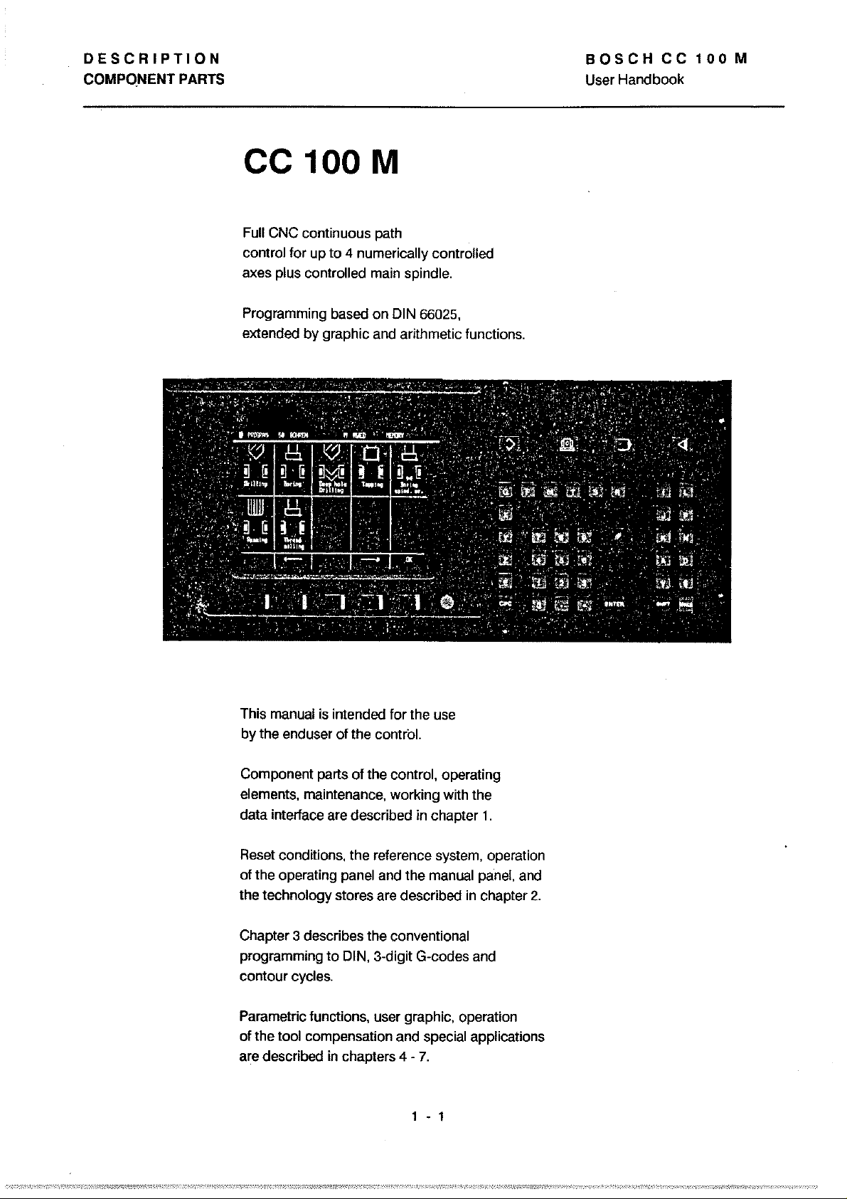
Full CNC continuous path
control tor up
axes plus controlled main spindie.
Programming based on
extended by graphie and arithmetic tunetions.
100
to
M
4 numerically controlled
DIN 66025,
manual
This
by the end user
Component parts
elements, maintenance, working with the
data interface are described in chapter 1 .
Reset conditions, the relerence system, operation
01
the operating panel and the manual panel, and
the technology stores are described
Chapter 3 describes the conventional
programming
contour
Parametrie lunctions, user graphie, operation
01
the tool compensation and special applications
are described
is
intended tor the use
ot
the contral.
ot
the control, operating
to
DIN, 3-digit G-codes and
cycles.
in
chapters 4 -
7.
1 - 1
in
chapter
2.
Page 10

DESCRIPTION
COMPONENT PARTS
BOSCH
User Handbook
CC
100
M
COMPONENT
PARTS
Operating Panel
graphie screen,
soft keys
main mode
input keyboard
Manual Panel
handwheel,
customer keyboard
reentry
start I stop I emergency stop button
I display distance to
10",
green
jog buttons, override switches
go
1 - 2
Logic
Modules:
CP/MEM
connections for 2 serial
data
panel,
and software module
Module
Displays for
- Ready (green)
- 24
- internal voltage
levels ok (green)
reset button
connections for:
- ready 2
-24V
SERVO
connections
5 incremental
measuring systems,
analogue outputs
time-critical
P I C
P L C
module:
110
devices, operating
external
V (green),
module:
module
connection
VDU,
PS 75:
for
signals
or
battery
Page 11
DESCRIPTION
COMPONENT
PARTS
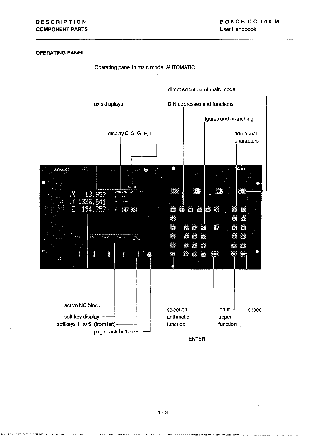
OPERATING PANEL
Operating panel
in
main mode AUTOMATie
BOSCHCC100M
User Handbook
axis displays
dislJlay
E,
S,
G,
F,
T
direet seleetion of main mode
DIN
addresses and funetions
figures and branehing
-----;
addttional
eharaeters
aetive
soft key
dislpla'(--
softkeys 1 to 5 (from
page back
....
leftll-----'
button------'
artthmetie
function
1 - 3
input
upper
funetion
ENTER
Page 12
SCRIPTION
IPONENT
PARTS
IUALPANEL
BOSCH
User
Handbook
CC
100
M
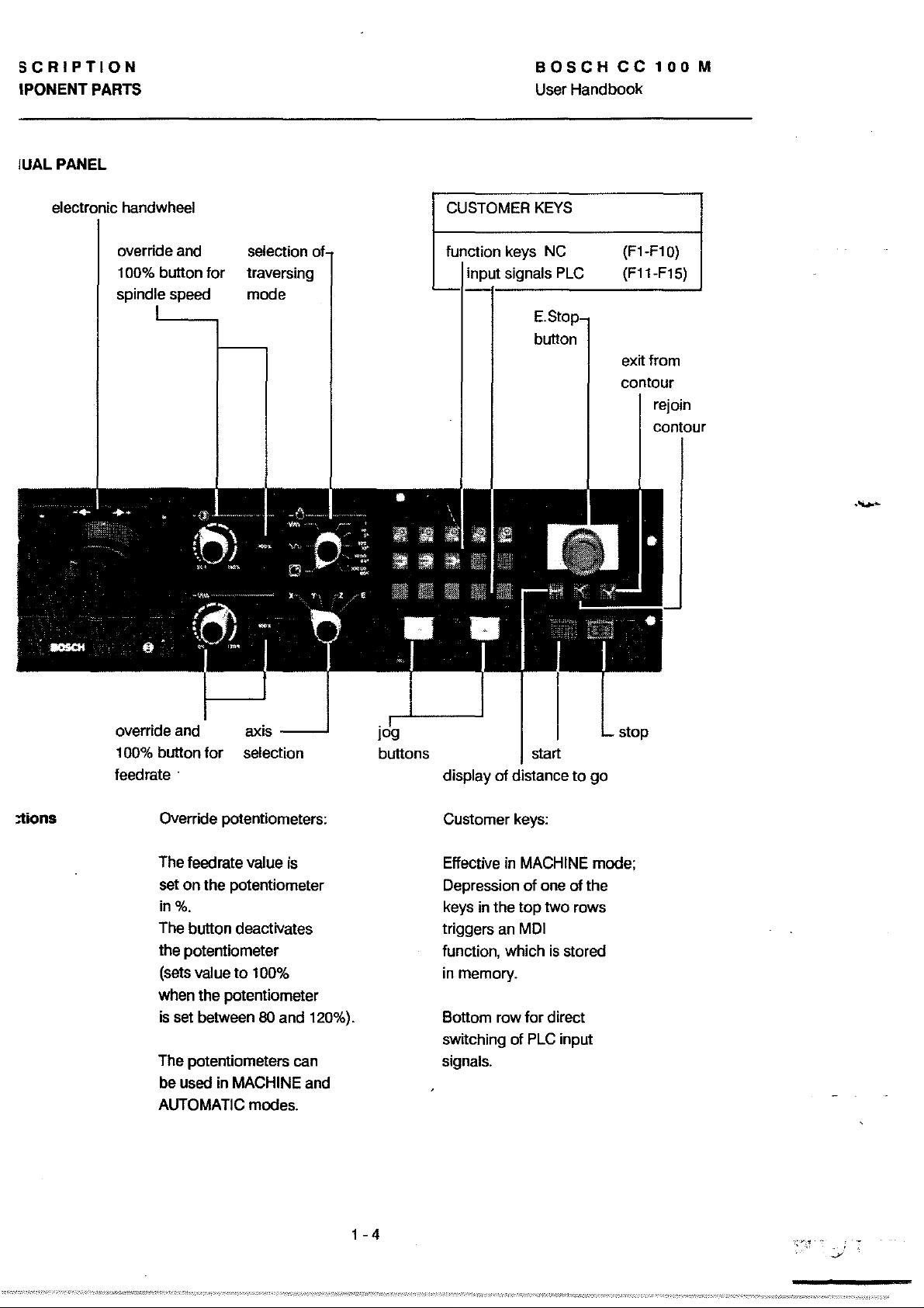
eleetronie handwheel
override and
100% button
spindie speed
lor
seleC1ion
traversing
mode
CUSTOMER
lunC1ion keys NC
input signals PLC
KEYS
button
(F1-F10)
(F11-F15)
extt
lram
eontour
rejoin
contour
::Iions
override and
100% button
leedrate .
lor
Override potentiometers:
The leedrate
on
the potentiometer
set
in%.
The button deaetivates
the potentiometer
value
(sets
when the potentiometer
is set between
The potentiometers can
be used in
AUTOMATIC modes.
__
axis
seleetion
value is
to
100%
80
MACHINE and
....J
and 120%).
buttons start
display
Customer keys:
Effeetive in
Depression
keys in the
triggers an
lunC1ion,
in memory.
Sottom row
swttehing
signals.
01
distanee
MACHINE mode;
01
one
top
two rows
MDI
whieh
is
ler
direet
01
PLC input
to
go
01
the
stored
stop
1 - 4
Page 13
DESCRIPTION
COMPONENT PARTS
BOSCH
User Handbook
CC
100
M
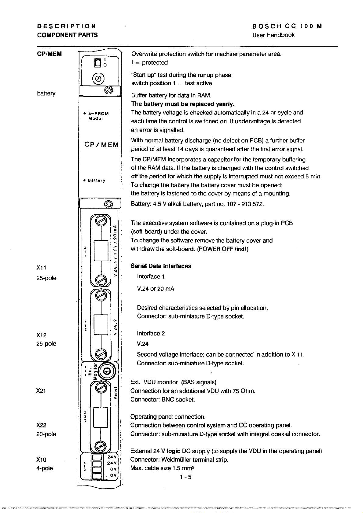
CP/MEM
battery
Xll
25-pole
tl~
®
@)
•
E-PRQM
Modul
CP/MEM
•
Battery
~
«
'I
,
,
,
,0~
'0'
0
'"
>-
,..
,..
Overwrite protection switch for machine parameter area.
I = protected
"Start up" test during the runup phase;
switch position 1
Buffer battery for data in
The
battery
The battery
each time the
an error is signalled.
normal battery discharge (no defect
With
period of at
,
The CP/MEM incorporates a capacitor for the temporary buffering
RAM
of the
off the period for which the
To change the battery the battery cover must be opened;
the battery is fastened
Battery: 4.5 V alkali battery, part no. 107 • 913 572.
The executive system software is contained
E
(soft-board) under the cover.
T
-
-
-
~
'"
>
0 change the software remove the battery cover and
withdraw the soft-board.
Serial Data
I
Interface 1
V.24
or20
= test active
RAM.
must
be
replaced
voltage is checked automatically in a 24
control is switched on. If undervoltage is detected
least 14 days is guaranteed after the first error signal.
data. If the battery is changed with the control switched
to
(POWER OFF first!)
Interfaces
mA
yearly.
on
PCB) a further buffer
supply is interrupted must
the cover
by
means
of
on
a plug-in PCB
a mounting.
hr
cycle and
not
exceed 5 min .
X12
25-pole
X21
X22
20-pole
Xl0
4-pole
,
,
2
":
~
N
>
,I
,.O@
~~g
e
"'~
..
e
•
"-
'I
,
2
,
1
24V
p
,
,
a
6.
c=-
~4V
ov
ov
Desired characteristics selected by pin allocation.
Connector: sub-miniature D-type socket.
Interface 2
V.24
Second voltage interface; can be connected in addition
Connector: sub-miniature D-type socket.
VDU
Ext.
Connection
Connector: BNC socket.
Operating
Connection between control system and
Connector: sub-miniature D-type socket with integral coaxial connector.
External 24 V
I
Connector: Weidmüller terminal strip.
Max.
monitor (SAS signals)
for
an additional
panel connection.
logic
DC supply (to supply the VDU in
cable size 1.5
mm
1 - 5
VDU
with 75 Ohm.
CC operating panel.
2
to X 11.
the
operating panel)
Page 14
DESCRIPTION
INTERFACES
INTERFACES, general
INTERFACES
BOSCHCC100M
User Handbook
The user can connect
up
to
2 external data
terminals at the CPfMEM.
20mA
V.24
Control Signals
DTR Data Terminal Ready:
DSR Data Set Ready: Status of permission
Note:
Data Lines
1 device of this type can be connected
This interface
andfor
With this type of interface one side is active (serves as source of current).
the other must
in the connections (see page
1 device of this type can be connected
This interface allows higher transfer speeds than the
more susceptible
Switch off handshake
is
particularly suitable for use where long distances are involved
where there is a high level of interference
be
made passive. This
HO.
1-11).
to
interference.
Status of readyness
by
means of a bridge. Pins 4 and 6 at the contral side.
to
X11
(see
page 1-5).
in
the surroundings.
is
achieved
to
X11
to
to
send is recognized (input signal).
by
specific pin allocations
or
X12.
TTY
interface but is
receive data is output (output signal).
TX
RX
Data output at the device sending the data.
Receipt
Make sure not
Only connect one device per interface
of data at the receiving device.
to
confuse the plugs when connecting the devices!
(V
.24f20mA) !
1 - 6
Page 15
OESCRIPTION
INTERFACES
OATAFORMAT
Control
Charac1ers
(ASCII)
1 start bit, 7 data bits, 1 stop bit, "even" parity bit .
(1
start bit, 7 data bits, 2 stop bits, "even" parity bit
DeI
Tape reader ON
DC2 Punch ON or output
It starts the transmission.
DC3 Tape reader
DC4 Punch
It interrupts (stops) the transmission.
STl<
Start
ETX
End
EOT
End of transmission.
01
01
OFF
text.
text.
or
input
OFF
or
or output
START.
START.
input
STOP.
Output comes
STOP.
Output comes Irom the controlling device.
BOSCHCC100M
User Handbook
lor
110 Bd)
lrom
the controlling device.
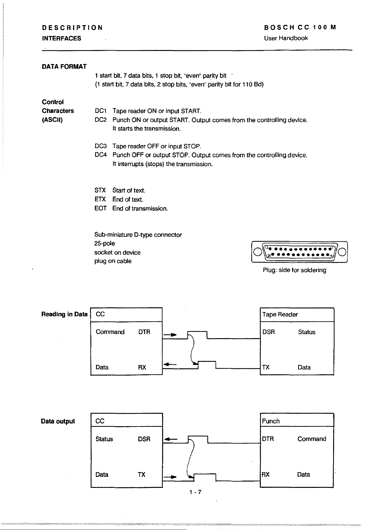
Reading
in
Oata
Sub-miniature D-type connector
25-pole
socket on device
plug on cable
CC
Command
DTR
-
Data
RX
-
1
..,
\~J·············~~O
O
J\\;zse
•••••••••••
Plug: side for soldering
Tape Reader
l
1
DSR
TX
Status
Data
,.//\
Oata
output
CC
Status
Data
DSR
Tl<
-
-
/
'.f
1 - 7
Punch
I
1
DTR
RX
Command
Data
Page 16
DESCRIPTION
INTERFACES
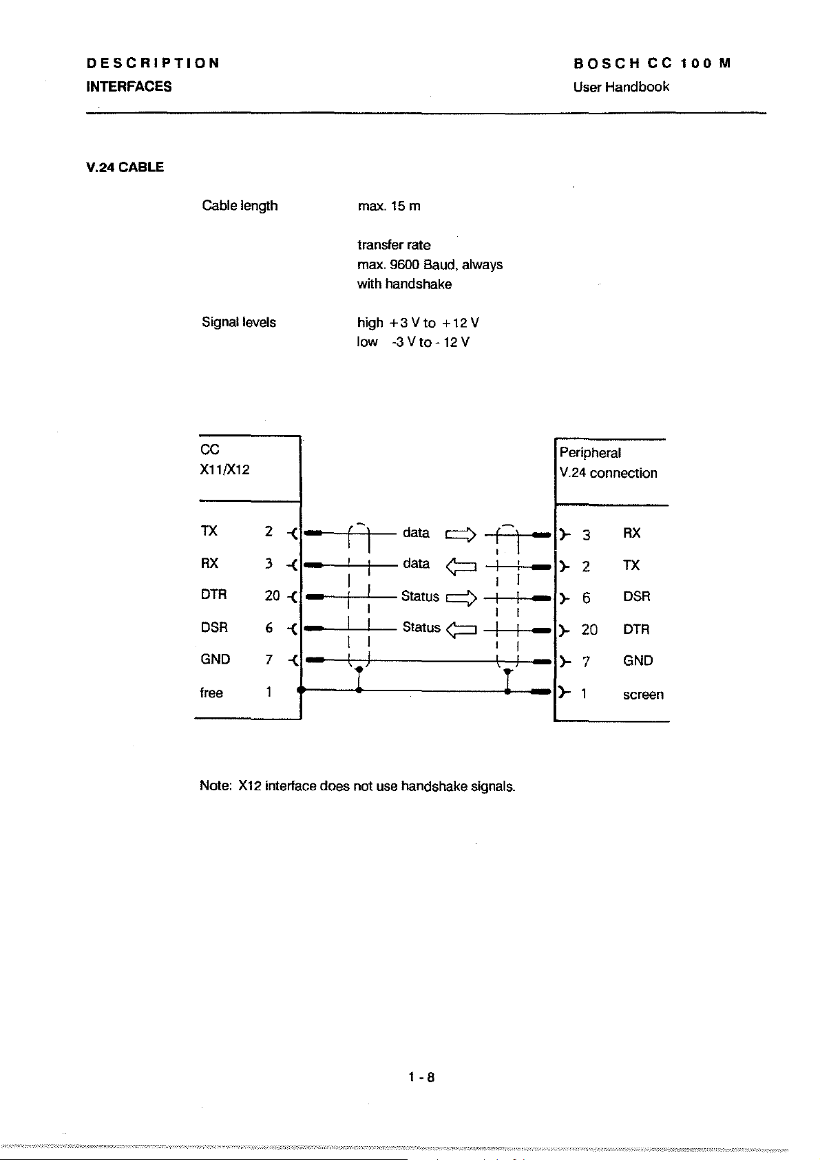
V.24CABLE
BOSCH
User Handbook
CC
100
M
Cable length
Signal levels
ce
X11/X12
Tl(
RX
DTR
DSR
GND
free
2
3
20
6
7
1
-<
-
-<
-
-<
-
-<
-
-<-
max.15 m
transfer rate
9600 Baud. always
max.
with handshake
+3Vto
high
low
-3 V
to -12
r-j
!
I
I
I
I
data
data
I
I
Status q
I
I
Status~
I
Iri
+12V
V
q
~
-
f
,
I
I
I
I
I
I
Ir!
,
I
,
,
I
I
I
I
I
Peripheral
V.24 connection
3
>-
-
2
>-
-
6
>-
-
20
>-
-
7
>-
-
)-
1 screen
RX
TX
DSR
DTR
GND
Note:
X12
interface does not use hand shake signals.
1 - 8
Page 17

DESCRIPTION
INTERFACES
20
mA
CABLE
BOSCHCC100M
User Handbook
CC active
Pin
A1location
Gable lengths:
Signal levels:
The
CC
serves as source of current:
CCX11
CC
active
CC
passive
Baudrates:
maxI 4800
maxI
300
high
low
maxI
eX1ernal
maxI
maxI 100 m
Bd
with handshake
Bd
without handshake
approx.
approx.
voltage drop 2 V
Peripheral
(e.g. Mini Cass)
15
m
20
0
mA
mA
RX+
RX-
TX+
TX-
DSR+ 14
DSR-
DTR+ 16
DTR-
Active
Active out
in
12
24
13
25
18
21
9
10
-<
-<
-<
-<
-<
-<
-<
-<
-<
-<
-
-
-
-
-
-
-
-
r-
I
I
I
I
I
I
I
I
I
I
I
I
I
I
I
I
I
I
I
'.-'
1
data
I
I
I
I
I
data
I
I
I
I
I
Status<;::=J I
I
I
I
!
I
Status
I
I
!
: I
-
-
j
~r
I
I
-
I
I
I
I
I
I
I
I
I
I
l J
I
I
I
t
I
I
I
I
I
I
-
-
-
-
-
-
ql
ql
)-
23
)-
13
)-
22
}-
12
}-19
}-
16
)-
11
}-
14
TX+
TX-
RX+
RX-
DTR+
DTR-
DSR+
DSR-
free
1
1 - 9
)-1
screen
Page 18
DESCRIPTION
BOSCHCC100M
INTERFACES
20
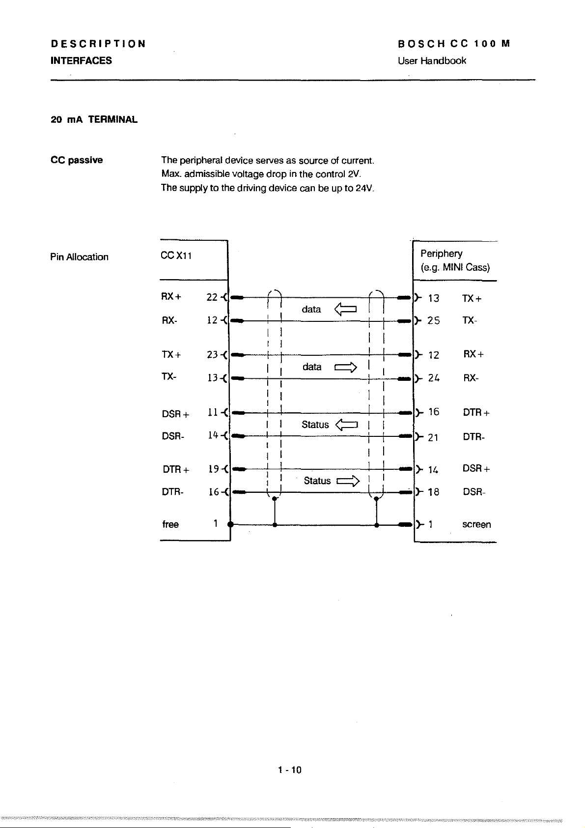
mA TERMINAL
CC
passive
Pin Allocation
The peripheral device serves as source of current.
Max.
admissible voltage drap in the contral
The supply
CCXll
RX+
RX-
TX+
TX-
DSR+
DSR-
DTR+
DTR-
to
the driving device can
22
12
-{
23-{
13-{
11-{
14
-{
19-{
16-(
-
-
-
-
-
-
-
n
I
I
I I
I
I
I
I
i
I
I
I
I
I
I
I
I
I
,
I
I
I
I
I
I
I
I
I
I
I
I
I
I
be
data
data q
Status
Status
2V.
up
to
24V.
~
<;=::J
=>:
fl
I
I
I
I
I
I
I
I I
I
I
I
User Handbook
-
-
I
I
I
-
I
-
I
I
,
I
-
I
-
I
I
-
:
'.
Periphery
(e.g.
>-
13
>-
25
>-
12
>-
24
>-
16
}-
21
>-
14
.
>-
18
MINI Cass)
TX+
TX-
RX+
RX-
DTR+
DTR-
DSR+
DSR-
free
1
1 -
10
}-1
screen
Page 19
DESCRIPTION
BOSCH
CC
100
M
PERIPHERALS
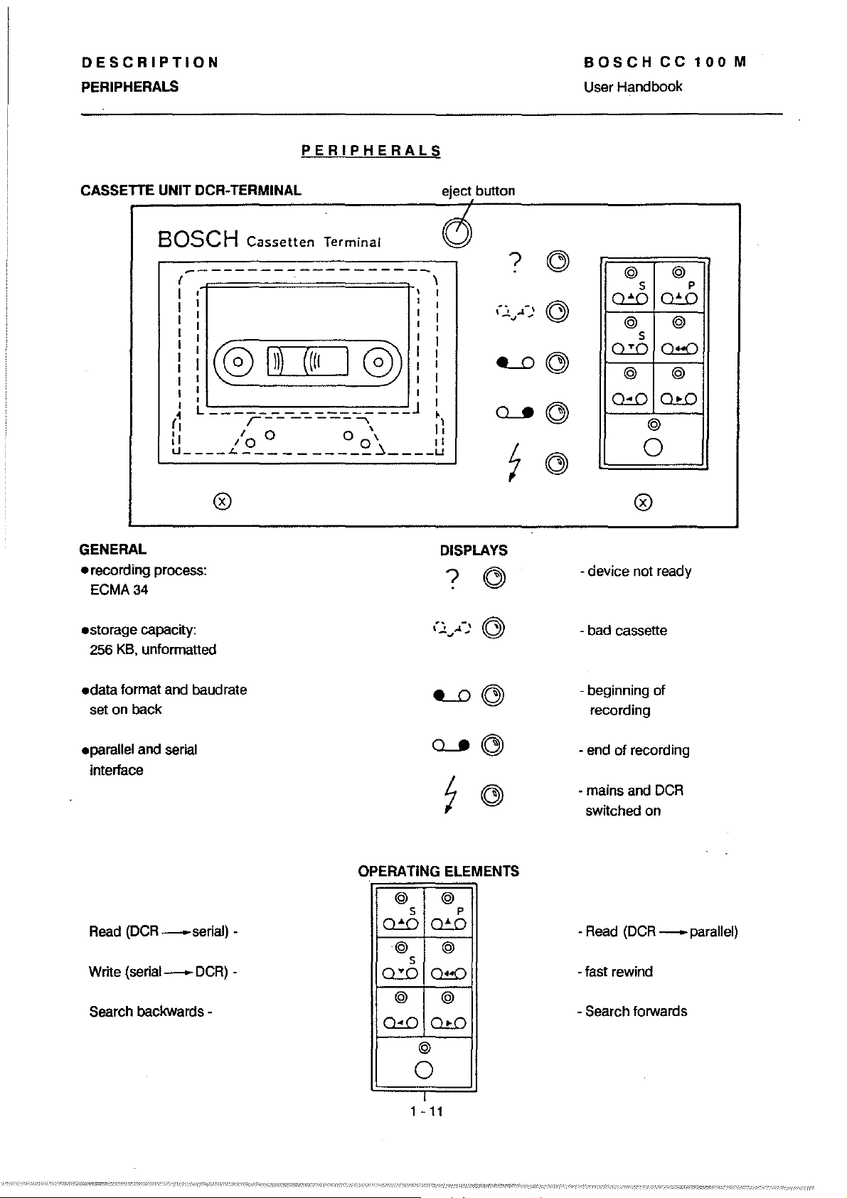
CASSETTE UNIT OCR-TERMINAL
BOSCH
-------------------
( \
I 1
I 1
I I
I 1
! (0
1 1 1
1 I 1
L J
1
(
1
1
"
1..1
____
Cassetten
I)))
r--
- - - -
I \
0
10
"-
__________
PERIPHERALS
Terminal
(((I
I 0) i
--
"""'
00'
~
____
eject button
~,
11
11
u
?
(",
,1.-,
-~
----.0
~
7
,
User Handbook
~
~
~
~
~
@ @
5
~
@
5
Q.:D
@ @
~
@
0
P
~
@
Q!!O
lli.O
GENERAL
•
recording process:
ECMA34
.storage
256
.data
set on back
.parallel and serial
interface
Read
Write
Search backwards -
capacity:
KB.
unformatted
format and baudrate
(OCR
_serial)
(serial-DCR)-
0
.
DISPLAYS
?
~
----.0
~
OPERATING ELEMENTS
@ @
5 P
-
~
Q.:D
~
~
@ @
5
O!!D
@
lli.O
@
7
@
~
~
~
- device not ready
- bad cassette
- beginning of
recording
- end
of
recording
- mains and
switched on
-Read
-fast rewind
- Search forwards
DCR
(DCR
- parallel)
1 -
0
1
11
Page 20

DESCRIPTION
PERIPHERALS
BOSCHCC100M
User Handbook
BOSCH
(OCR
REAo
- CC100
Cassetten
M)
Terminal
I
WRITEI
(CC100 M -
insert cassette
Q.5O
0
,
@
OCR)
?
.
....
\
...t.,..
~
QJ
7
I
-,
..
",
Q)
ö)
~
~
~
@
s
~
Q.:D
~
~
@
s
O!!O
@
Qill
@
0
WRITE
(CC100
M-
insert cassette
@
@
@
p
11
OCR)
data can now be
transferred
•
@S
0lD
,
@
O=D
,
cassette winds forw. I
. a little, then stops
I
,.
data can now
I
stored
j
@
0
I.
endmarker isgenerated I
be
t
,
@
Q.5O
cassette winds forwards
@
o
I
data can now be
stored
@
o
1
-12
Page 21
DESCRIPTION
PERIPHERALS
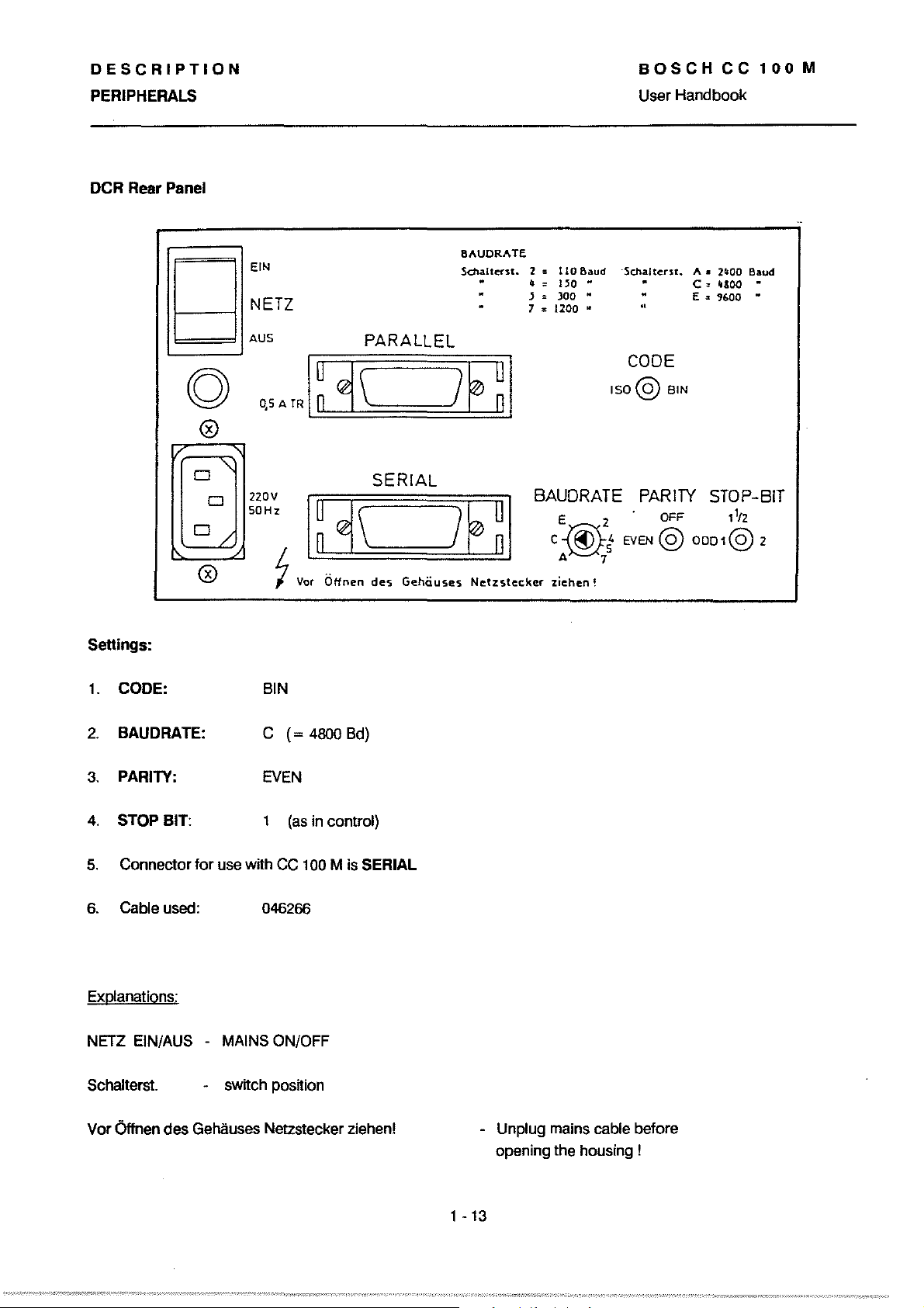
OCR
Rear Panel
BOSCH
User Handbook
CC
100
M
g
g
@
Settings:
1.
CODE: BIN
E[N
NETZ
AUS
0,5
A IR
8AUDRATE
Schalterst.
PARALLEL
I~~
~
~\
~}:h:!:!JE
SERIAL
~
I
2::
110
,,'"
}=)OO
7
Baud
150
..
..
::
1200
..
BAUDRATE
·SchalterS!.
..
..
CODE
[SO@
PARITY
EVEN
8[N
OFF
@
A.
2/100
C:
"300
E",
'1600
STOP-BIT
l1tz
OD01@
Baud
..
..
2
I·
BAUDRATE:
2.
PARITY:
3.
4.
STOP BIT: 1
5.
Connector tor use with CC 100 M is SERIAL
6. Gable used:
Explanations:
NETZ EIN/AUS MAINS ON/OFF
Schalters!. switch position
Vor Öffnen des Gehäuses Netzstecker ziehen!
C
(=
EVEN
(as
046266
4800 Bd)
in control)
Unplug mains cable betore
opening the housing !
1
-13
Page 22

DESCRIPTION
BOSCHCC100M
PERIPHERALS
MINI CASSETIE UNIT
GENERAL
User Handbook
DISPLAYS
.recording
ECMA34
.storage
20
KB
.data
set on back
.automatic
after switch-on with
"Ready"
.serial
V24or20
process:
capacity:
each side
format and baudrate
self-diagnosis
indicator
interface with
mA
OPERATING ELEMENTS
Write button
(data transfer
CC 100 --Mini-Gass)
I[
0
0
l
0 error indicator
Error
0 ready indicator
Test
Reset button
I1
I
1
0
-14
l
Read button
(data transfer
Mini-Gass
__
CC 100)
Page 23
DESCRIPTION
PERIPHERALS
BOSCH
User Handbook
CC
100
M
Rear Panel
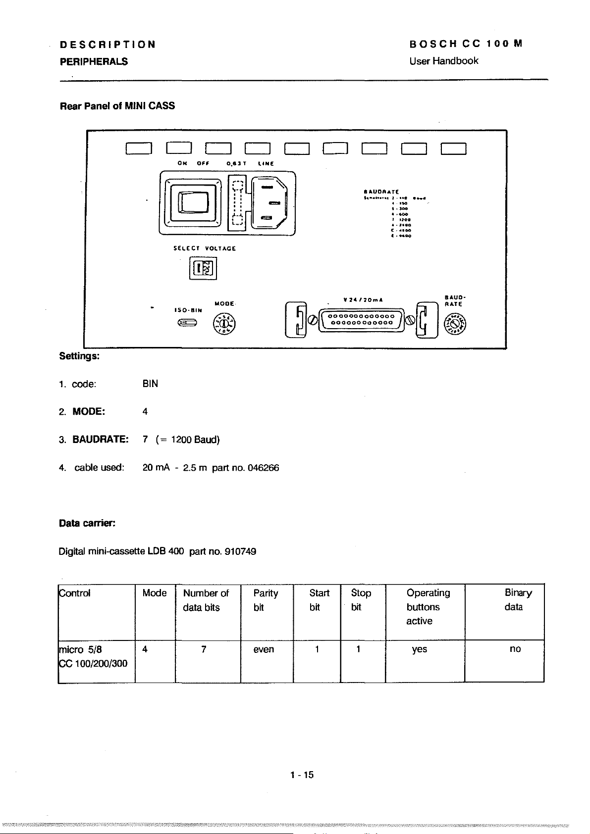
Settings:
1.
code:
of MINI CASS
000000000
ON
SfLECT
BIN
OFF
VOlTAGf
0.61 T llNE
MODE·
=
-~
[]0
y
24
12O","
0000000000000
000000000000
.AUDRATE
l
.......
·..
..... • ......
• • w
..
-
"
·1-
I
noo
a.
HOG
c·uoo
•
·_00
[J
BAUO-
RATE
!~}
......
2. MODE: 4
3.
BAUDRATE: 7
4.
cable used:
Data carrier:
Digttal mini-cassette
~on1rol
micro
pe
5/8
100/200/300
(=
20
mA -
LDB
Mode
4
1200
Baud)
2.5
m part no. 046266
400
part no. 910749
Number of
data
Ms
7
Partty
btt
even
Start
btt
1
Stop
btt
1
Operating
buttons
active
yes
Binary
data
no
1 -
15
Page 24

DESCRIPTION
BOSCH
CC
PROGRAM HEADER User Handbook
100
M
EXTERNAL PROGRAM PRODUCTION
following text explains the methods by which part
The
programs and part program type subprograms (or cycies)
are produced.
Such programs are constructed lrom program language elements
to
DIN 66025 and can be produced by one of the lollowing
methods:
1. via keyboard input, using the program editor
2. via the manual panel with 'Teach In',
3. via a programming unit onto a data carrier (paper
tape, for instance), outside the
PROGRAM
HEADER
in
the
Ne
Ne
in
the
Ne
Note:
4. by computer, outside the
Programs produced outside the
Ne
machine code and the
In
addition programs which are input from a data carrier
(tape
or
digital cassette)
Ne
Ne
must conform to the
Ne
syntax.
or
via an interface (V24/20 mAl
must have aleader (header) and a trailer. Leader and
trailer, the beginning
as
weil
as
the program identifications
of
data blocks must be provided
When
data needs
of the individual program
to
be transmitted the external data carrier
01
in
the correct format.
Iines,
the header lines
must be activated before the contro!.
1 -
16
Page 25
DESCRIPTION
PROGRAM HEADER
1 2 J L 5 6 7 8 9 "0 »
54
1
2
,
=
121314 15
I F
58.7
,
5
6
7
1
2
,
,
5
6
7
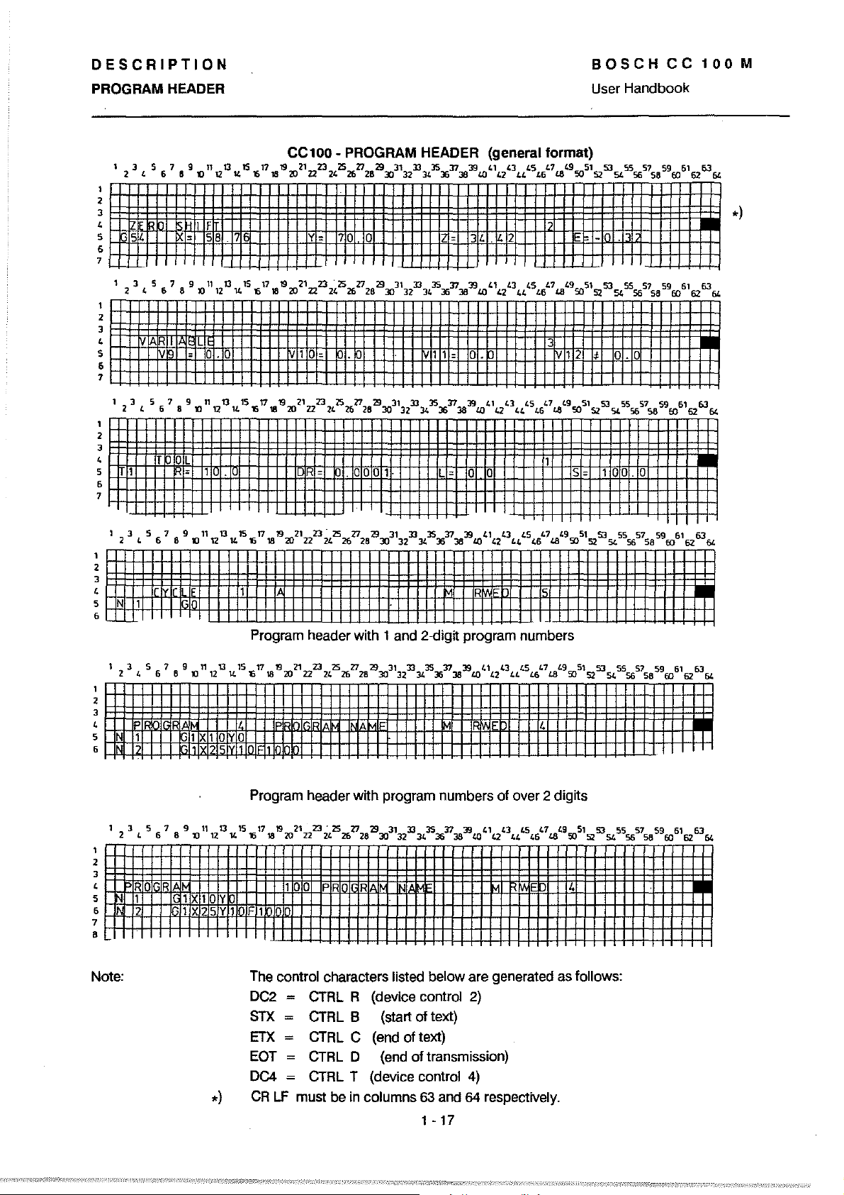
CC100 - PROGRAM HEADER (general format)
17
'6
18
'S
1!J"l'12232,"526'Z12l3:r;3'32D343'S"Xln38J91.l)
y =
70
1.1'2
'3
34.
2 E -
44
'5
1.6"
LS,9S05'S2SJSLS55651S8
BOSCH
User Handbook
CC
590061
100
62 6364
I
-
M
l
I
.)
I
1
2
,
,
5
6
7
•
Note:
Program header with 1 and 2-dign program numbers
Program header with program numbers of over 2 digits
The control characters listed below are generated as folIows:
DC2
= CTRL R (device control
STX
= CTRL B (start of text)
ETX
=
CTRL
C (end
EOT
=
CTRL
0 (end
DC4
= CTRL T (device control
CR
LF
muS!
be
in
columns
of
text)
of
transmission)
63
and
2)
4)
64
respectively.
1 - 17
Page 26
DESCRIPTION
PROGRAM HEADER
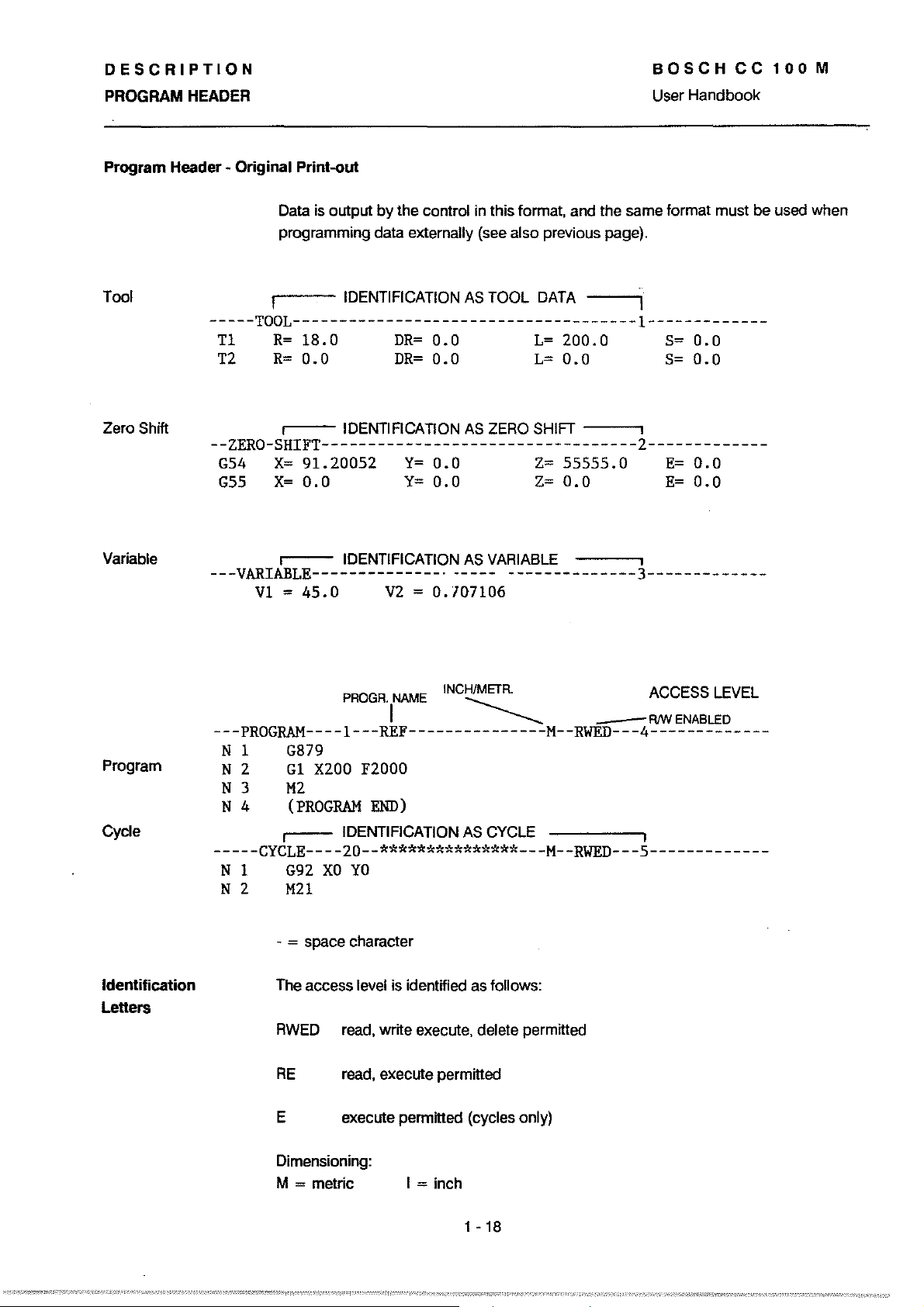
Program Header • Original Print-out
BOSCHCC100M
User Handbook
Taol
Zero Shift
Variable
Data is output
programming data externally (see also previous page).
I IDENTIFICATION
by
the control in this format, and the same format must be used when
AS
TOOl
DATA
I
-----TOOL-------------------------------------1------------Tl
T2
R=
18.0
R=
0.0
I IDENTIFICATION
DR=
DR=
0.0
0.0
L=
200.0
L=
0.0
AS
ZERO SHIFT I
--ZERO-SHIFT----------------------------------2------------G54
G55
---VARIABLE--------------·
X=
91.20052
X=
0.0
I IDENTIFICATION
VI = 45.0
V2
Y=
0.0
Y=
0.0
AS
-----
= 0.107106
Z=
55555.0
Z=
0.0
VARIABLE I
·_------------3-------------
S=
S=
E=
E=
0.0
0.0
0.0
0.0
Program
Cycle
Identification
LeIters
PROGR.
NAME INCH/METR. ACCESS
I
~
_
R/W
ENABLED
lEVEL
---PROGRAM----1---REF---------------M--RWED---4------------N 1
N 2
N 3
N 4
G879
GI
X200
F2000
M2
(PROGRAM
I IDENTIFICATION
END)
AS
CYClE
I
-----CYCLE----20--***************---M--RWED---5-------------
N 1
N 2
G92
XO
YO
M21
- = space character
The access level is identified as
RWED
RE
E execute permitted (cycles only)
read, write execute, delete permitted
read, execute permitted
folIows:
Dimensioning:
= melric
M
I = inch
1 - 18
Page 27
DESCRIPTION
PROGRAM HEADER
PROGRAM HEADER IN DFS FORMAT
BOSCH
User Handbook
CC
100
M
Different
possibilities
Explanations
The ce 100 program header in
header format of the ce
the future.
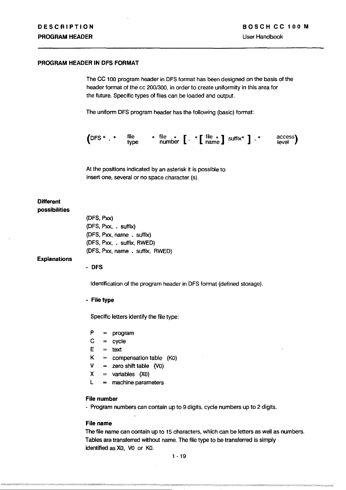
The uniform
(DFS'
At the positions indicated by an asterisk it
insert one, several or no space character (s).
(DFS, Pxx)
(DFS, Pxx, •
(DFS, Pxx, name . suffix)
(DFS, Pxx, • suffix,
(DFS,
-
DFS
Specific types
DFS program header has the following (basic) format:
, •
Pxx, name • suffix,
file
type
suffix)
200/300, in order
RWED)
DFS
format has been designed on the basis
to
of
files can be loaded and output.
• file • [ • [ file • ]
number'
is
RWED)
create uniformity in this area for
name
possible
suffix'
to
]
•
of
the
access)
level
Identification
-
Filetype
Specific letters identity the file type:
P
C
E
K compensation
V
=
X variables
L
=
File number
- Program numbers can contain up
File name
The file name can contain
Tables are transferred without name. The
identified as
of
the program header in DFS format (defined storage).
program
cycle
text
table
zero shit! table
machine parameters
XO,
VO
(XO)
or
up
KO.
(VO)
to
(KO)
to
9 digits, cycle numbers
15
characters, which can be letters as weil as numbers.
1
-19
file type
to
be transferred
up
to
2 digits.
is
simply
Page 28
DESCRIPTION
PROGRAM HEADER
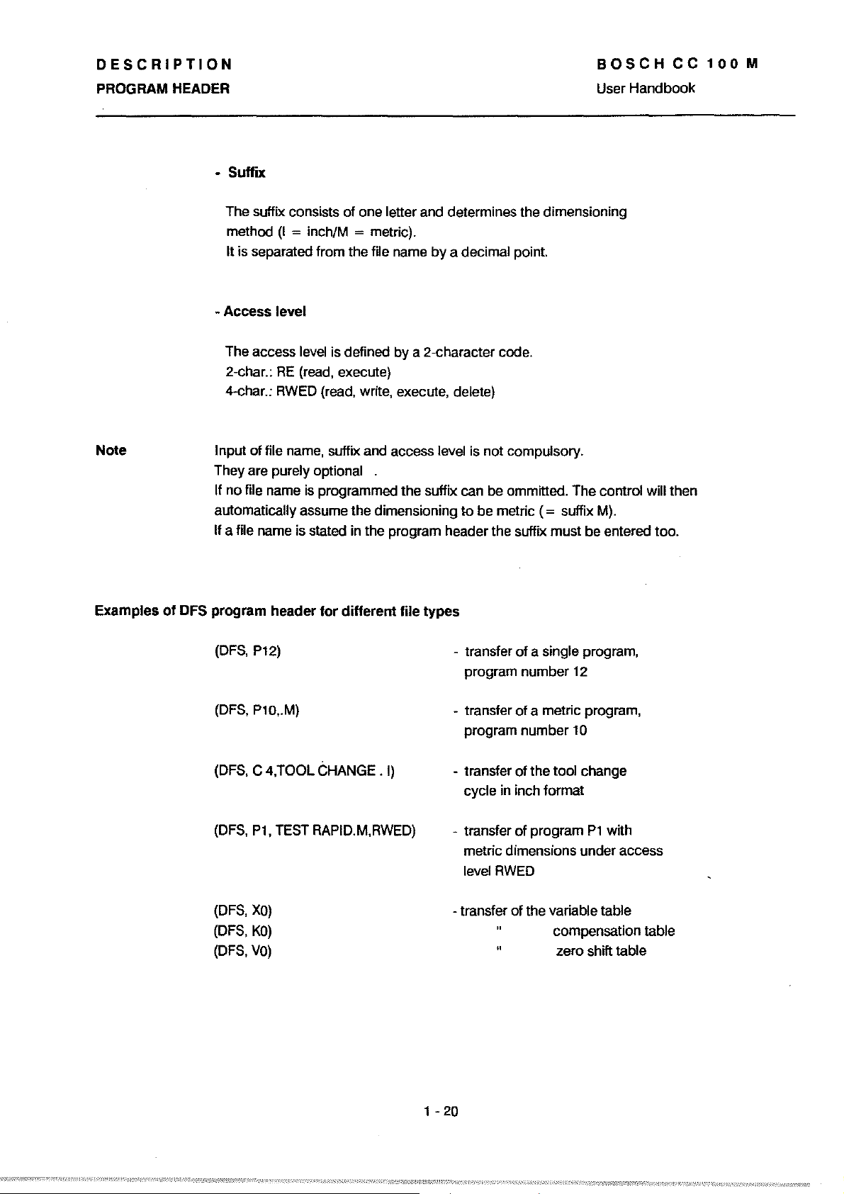
- Suffix
of
The suffix consists
method
It is separated fram the file name
(I
= inch/M = metric).
one letter and determines the dimensioning
by
a decimal point.
BOSCH
User Handbook
CC
100
M
Note
Examples
- Access
The access level is defined by a 2-character code.
2-char.:
4-char.:
Input
They are purely
If no file name
automatically assume the dimensioning to be metric
If a file name is stated in the program header the suffix must be entered too.
01
DFS program header
(DFS,
(DFS,
level
RE
RWED
cf
file name, suffix and access level is not eompulsory.
P12)
P10,.M)
(read, execute)
(read, write, execute, delete)
optional .
is
pragrammed the suffix can be ommitted. The contral will then
(=
suffix
M).
lor
different
Iile
types
- transfer
pragram number
- transfer
program number
of
a single program,
12
of
a metric program,
10
(DFS,
C 4,TOOL CHANGE.
(DFS,
P1,
TEST RAPID.M,RWED)
(DFS,
XO)
(DFS,
KO)
(DFS,
VO)
I)
- transfer
cycle in inch format
- transfer
metrie dimensions under aceess
level
- transfer
1 -
20
of
the tool change
of
program
RWED
of
the variable lable
compensalion lable
zero shift lable
Pl
with
Page 29
DESCRIPTION
PROGRAM HEADER
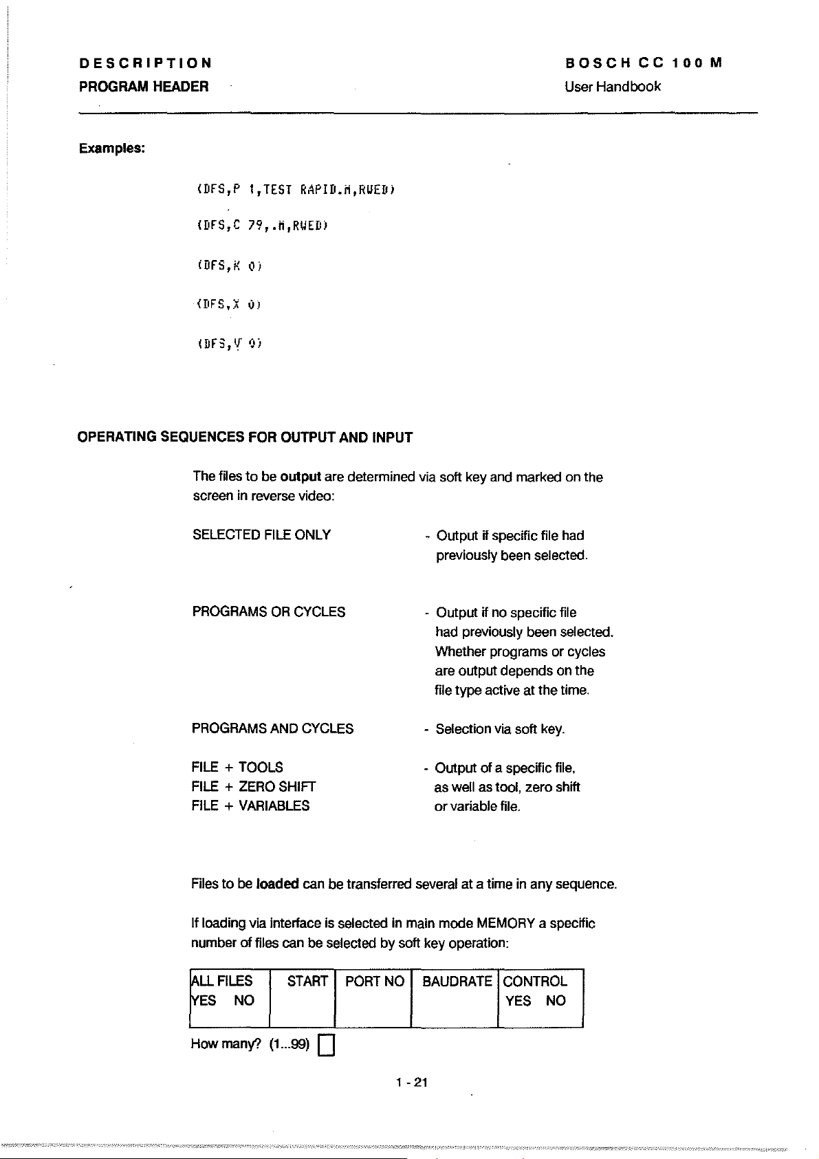
Examples:
BOSCH
User
Handbook
CC
100
M
(DFS,P
(DFS,C
iDFS,K
OPERATING SEQUENCES FOR OUTPUT AND INPUT
The files
screen in reverse video:
SELECTED
1,TEST
RAPID.M,RUED)
79,.H,RUEDI
01
to
be
output
FILE
ONl
are determined via soft key and marked on the
Y
- Output if specific file had
previously been selected.
OR
PROGRAMS
PROGRAMS AND
FILE +
FILE + ZERO SHIFT
FilE
Files
If loading via interface is selected in main mode MEMORY a specific
number
lALL
!vES
TOOlS
+ VARIABLES
to
be
of
FILES
NO
CYClES
loaded
files can
START
- Output if no specific file
had previously been selected.
Whether programs or cycles
are output depends on the
file type active
CYClES
can
be
transferred several at a time in
be
selected by soft key operation:
PORT
- Selection via soft key.
- Output
as weil as tool, zero shift
or
variable file.
NO
BAUDRATE
at
the time.
of
a specific file,
any
CONTROl
YES NO
sequence.
How
rnany?
(1
...
99) 0
1 -
21
Page 30
DESCRIPTION
PROGRAM HEADER
BOSCH
User Handbook
CC
100
M
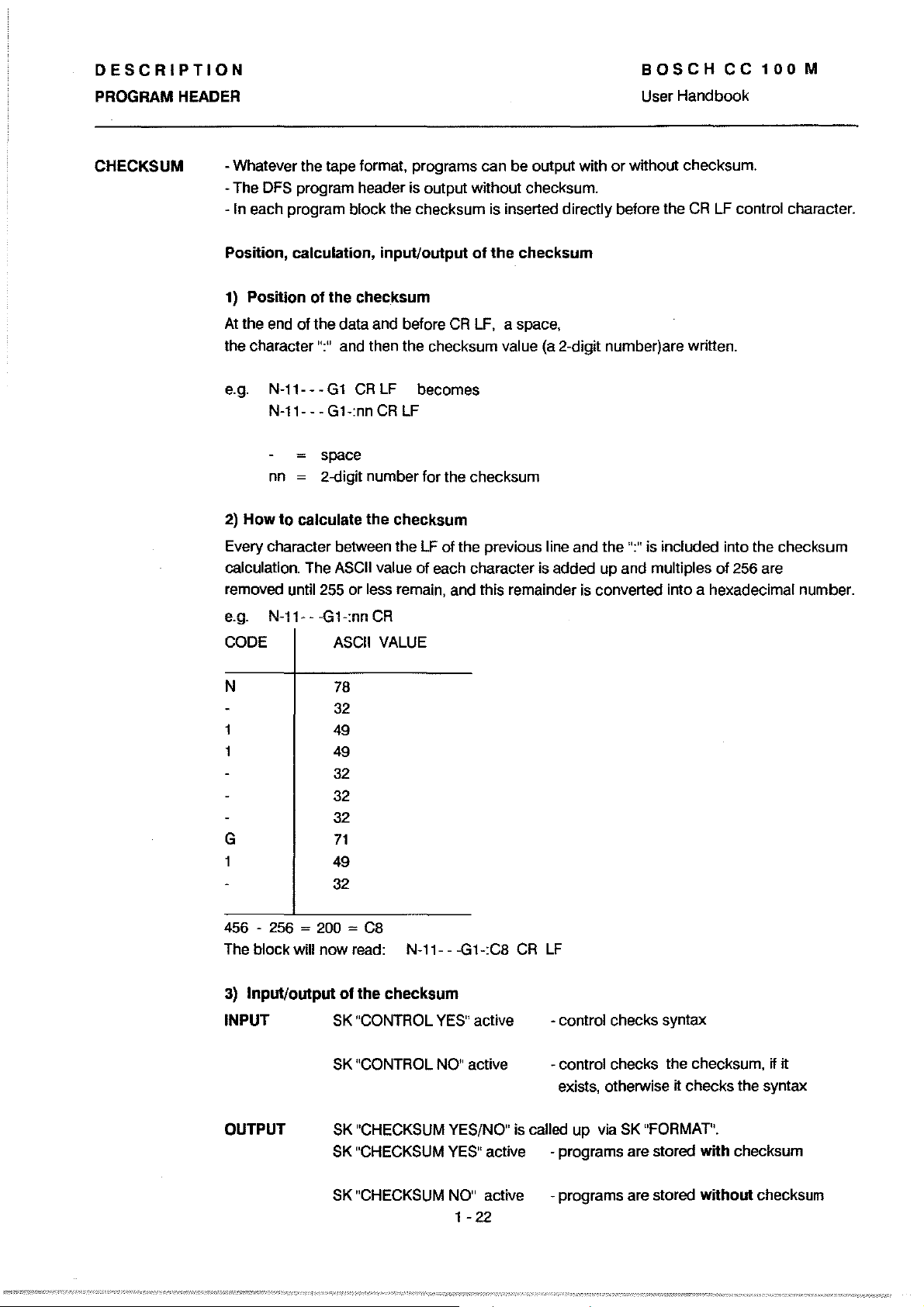
CHECKS UM
-Whatever the tape format, programs can be output with
-The
DFS
program header is output without checksum.
In
each pragram block the checksum is inserted directly before the
-
Position, calculation, input/output
1) Position
At
the
the character
e.g.
2)
How
Every character between the
calculation. The
removed until 255 or less remain, and this remainder
e.g. N-11---G1-:nnCR
CODE
of
the
checksum
end
of the data and before
":"
and then the checksum value
N-11- - N-11---G1-:nnCRLF
nn
to
G1
CR
LF
space
2-digit number for the checksum
calculate the checksum
ASCII
value of each character is added up and multiples of 256 are
ASCII
VALUE
becomes
LF
of
the
checksum
CR
LF,
a space,
(a
2-digit number)are written.
of the previous line and the
or
is
converted into a hexadecimal number.
without checksum.
CR
LF
contral character.
":"
is included into the checksum
N
78
32
1
1
49
49
32
32
32
G
71
49
32
456
- 256 ~ 200 =
The
block will now read: N-11- - -G1-:C8
3) Input/output
INPUT
OUTPUT
C8
of
the checksum
SK
"CONTROL
SK
"CONTROL
SK
"CHECKSUM YES/NO" is called up via
SK
"CHECKSUM
YES"
NO"
CR
LF
active -contral checks syntax
active
YES"
active - pragrams are stored with checksum
- control checks the checksum,
exists, otherwise it checks the syntax
SK
"FORMAT".
if it
SK
"CHECKSUM
NO"
active -programs are stored without checksum
22
1 -
Page 31

2. 0
PER
A
TIN
G
Page 32

OPERATING
MAIN MODES
BOSCHCC100M
User Handbook
SURVEY The operation
directly selectable by pushbuttons:
EDIT
W
working with
stored data
display
input,
modification
programs,
subprograms,
cycles,
tools
zero shifts
variables
input and
output via
data interfaces
V.24/20 mA
baud rates
automatie
generation
header lines
for PROGRAM/
CYCLE
01
etc.
01
the control
MACHINE
00
manual
operation
direct execution
without storage
01:
execution
reference axes,
relerence cycle,
MOl,
manual
operation,
teach
customer keys
handwheel
jog buttons
distance
display
MAIN
is
subdivided into the following main modes, which are
01
cycles
machine,
in
to
go
MODES
AUTOMATIC INFO
C2J
execution
programs information
execution of status
stored
programs, cycles
execution deletion of:
continuous/ programs,
block by block,
variable
step size,
block
break points, control reset
reentry
with/without
path compensation only for machine
toollength tool builder
compensation
CPC test
distance to
display
milling logbook
conditions set clock
of
selection,
go
@]
additional
NC/lO, axis
displays, error list
variables,
tool/zero shift
tables
MTBSERVICE
SERVICE
load M-parameters
mode
read in text
displays,
is
The active main mode
01
To come out
Use the page back button
then seleet new mode. Exception: For change-over
no paging back required.
To come
Select a different main mode directly. The old main mode
(display flashes) and can be reactivated
the current main mode altogether:
out
of
the current main mode temporarily:
displayed continuously in the top right corner
to
revert through the levels until the 1 st soft key level
by
2 - 1
01
the screen.
is
reached,
MEMORY/EDIT
is
retained in the background
pressing the relevant mode key once more.
to
AUTOMATIC
Page 33
OPERATING
MAIN
MODES
BOSCH
User
Handbook
CC
100
M
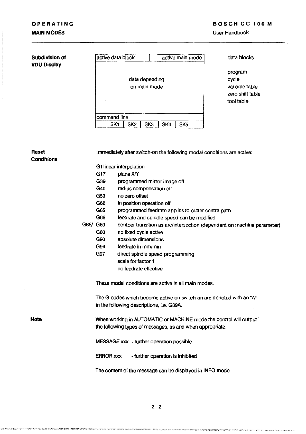
Subdivision
VDU
Display
Reset
Conditions
of
active
data
block
data
depending
onmain
command
Immediately after switch-on
G
1 linear interpolation
G17 plane
G39 programmed
G40 radius compensation off
G53
G62
G65
G66
G68/ G69
GOO
G90
G94
G97
line
SKl
I SK2 I SK3 J SK4 I
XJY
no
zero offset
in position operation off
programmed !eedrate applies
!eedrate and spindie speed can
contour
no
absolute dimensions
leedrate in
direct spindie speed programming
scale
no
transition
flXed cycle active
lor
lactor
leedrate effective
I
mode
mirror
as
mm/min
1
active main
mode
SK5
the
!oliowing
image off
arc/intersectiori (dependent
modal
to
cutter
be
conditions are active:
centre
modHied
data
blocks:
program
cycle
variable table
zero shift table
tool
table
path
on
machine parameter)
Note
These modal conditions are active in all main modes.
The G-codes which
in the lollowing descriptions,
When
working
the
lollowing
MESSAGE
ERRORxxx
The content
xxx
of
become
in AUTOMATIC
types
01
messages, as and
- further operation possible
-
lurther
the
message can
active
on
Le.
G39A.
or
MACHINE
operation is inhibited
be
displayed in INFO mode.
switch-on are denoted with an "A"
mode
the control will
when
appropriate:
2-2
output'
Page 34

OPERATING
MAIN MODES
EDiT
BOSCHCC100M
User Handbook
Access
Access
10
Data
Levels
In this main mode all user data can be handled (see EDITOR).
Selectable data blocks:
-tool table
- zero shift table
- variable table
- programs
-
cycles
The menue for part programs and cycles can be paged forwards
with soft key
Unauthorized accessing of the data can be prevented via
softkey operation. Execution
The access levels are expressed as folIows:
-
RWED
-
RE
- E only executing is possible (cycles only)
"NEXT
read, write, execute and delete are possible
only reading and executing are possible
PAGE".
is
always permitted.
Dimensioning
Commands
Data
Interfaces
Copy
The dimensions can be selected by soft key to be in metric
Display in index and in "active datablock" line:
- M metric
-I
inch
Under this
- resequence block numbers
- transfer program
- rename a
- inch/metric
See chapter on "Data Handling"
Programs stored
The user must enter a new file name and the control will selee! the file number.
SK the following functions are available in 2 levels:
-
to
a cycle - file protection
file
in
the memory can be duplicated with SK function
- delete file
or
copyfile
inch.
"COPY".
2-3
Page 35

OPERATING
MAIN
MOOES
BOSCH
User
Handbook
CC
100
M
arrow
edit line
cursor
Cursor
Functions
r---.
r-)
-I
SEARCH;I-I
GRAPHIC
Switch-over
Scrolling
simultaneous actuation
t INSERT
between MODIFY/INSERT
blocks up/down
-'-
SCROLL 1 r IMODIFY
by
01
1-
Selection
or
"CYCLES", program name
or
number
SK"EDIT"
The position
indicates
being worked
block
edit line
cursor (bright rectangle)
....
;==1=-11
via SK "PROGRAMS"
01
which
is repeated in the
which
or
I
the
arrow
line is
with. This
contains a
MODIFY
INSERT
t"
I + I SCROLL
Block
Selection
Search
Functions
Delete
Line
Delete
Modify
Insert
Moving cursor sideways
cursor
The
at which a letter is
A characteristic string (sequence
characters)
- individual character
- content
- First delete individual character,
- then key in
- enter
is placed
lrom
of
the line
new
new
character(s)
to
the right
to
be inserted/modified.
the
required line is entered, i.e. G41.
to
the left
to
the right
character(s)
01
01
....
01
the position
olletters,
the
the cursor is deleted
numbers and
cursor
I
I MODIFY I
[SHIFTJ
[2]
8
I INSERT
'[ENTER]
[
ff
1
2-4
Page 36

OPERATING
MAIN
MODES
MACHINE
BOSCH
User Handbook
CC
100
M
MANUAL MACHINE
The manual panel is always aetivated
REFERENCE
AXES
drMng to
the referenee
point
in
one or
several
axes
(all)
referenee eycle
call (eyele
start button
OPERATION
REFERENCE
CYCLE
input
direet exeeution;
exeeution with
e.g.
see
79)
of
instructions for
GOl
Xl00
page
2-6
in
MACHINE mode.
MOl
NC start
START,
TEACH
IN
INCH
METRIC
switehing of
dimensioning
unit
INCH-METRIC
TEACHIN
Reeording of elements of a sampie eontour (see
__
----------------------~
p.
2 -
7)
2-5
Page 37

OPERATING
MAINMODES
MOl
After SK selection
the
relevant data has been entered. The execution is initiated
the
with
Under the
milling
as weil as the user-definable
start button.
SK
cycles can be selected, parameterized and executed,
01
HELP
MOl one
the
block
can be executed after
permanently stored drilling and
cycles.
BOSCHCC100M
User
Handbook
Note:
REFERENCE
AXES
I HELP
MTB-specific soft keys (cycles)
- It is
not
possible
while a block/cycle is being executed.
- G41/G42 are not penmitted.
-
MTB cycle PRIOTITY ROUTINE can not be called up.
REFERENCE
CYCLE
..
to
return
to
MOl
previous SK levels
TEACHIN
! BORING
CYCLES
INCH
METRIC
I CLEAR
BLOCK
!CONTOUR
CYCLES
- Axes which have been driven onto the software limit
switches can only be moved by means
buttons
When working in manual mode the type
- With
in incremental steps
The max. leedrate corresponds
machine parameter
-The electronic handwheel can be activated
- Change-over between leed and rapid.
the
11
+.
1110
jog
buttons the axes can
(01
1,10,100,1000
lor
manual leed
in reverse direction.
to
of
the JOG
01
traversing movement needs
be
traversed individually
or
10,000 increments).
the
limit detenmined
(1
- 120,000 mm/min).
lor
indMdual axes.
2-6
by
the
to
be defined:
Page 38

OPERATING
MAINMODES
TEACH IN
Definition
MOl
function
Operating
BOSCHCC100M
User
Handbook
By
tracking the outline
contour leatures are recorded by key actuation (soft key
During this procedure the control stores the position values
A circular movement is generated
(soft key
As in MDI mode blocks can be keyed in. The data is translerred into memory
wtth
CIRCLE COMPUTE).
SK
"RECORD".
01
a sampie
contour
by
positioning
with the machine the specilic
RECORD).
01
all axes.
to
three points
01
the circle
Main mode MACHINE (
REFERENCE
AXES
IRECORD
Function
Keys
Storing posttions
-
Storing entered blocks
-
- Storing posttions
- Automatie calculation
-The CC 100 calculates circle data
(SK 'RECORD POINT
- Circular interpolation
11
Key in
memory
,S,
)
RECORD
CIRCLE
COMPUTE
REFERENCE
CYCLE
01
moved axes
01
blocks generated internally
G2/G3
a linear movement is
GO/Gl
before the linear movement and transfer into
wtth
SK
RECORD.
MDI
ICIRCLE
COMPUTE
01
circles
lrom
3 scanned points
1', 'RECORD POINT 2' and 'RECORD POINT 3')
is also modal in TEACH IN mode.
to
lollow
GO/Gl
must be programmend:
TEACH
IN
INCH
METRIC
ICLEAR
BLOCK
CLEAR
BLOCK
- Clearing blocks which have not yet been stored from the edtt line.
2-7
Page 39
OPERATING
BOSCHCC100M
MAINMODES
TEACHIN
Calculation
Circles
of
with
Parameter R
Display
Note
User Handbook
The control
generates the circular contour.
The current axis position is the
The display
G2/3
The block is stored with soft key RECORD.
- The
I1
a program with this name
has the newly entered TEACH IN lunctions added
I1
several independent programs are to be generated via TEACH IN, the old
program mus! lirst be renamed in EDIT mode with
calculates the radius R
will
show the last axis position with the calculated radius.
X...
Y...
R.
CC
100
automatically generates a program with the name ''TEACH IN".
••
lrom
the 3 recorded axis positions and
Ist point
is
al ready stored in the memory, this program
lor
the calculation
to
it.
SK
RENAME.
01
the circle.
Switching
is not permitted.
Should it be attempted an error message will be displayed:
"inch/metric selection
of
the dimensioning unit INCH/METRIC during TEACH IN operation
incorrect".
2-8
Page 40

OPERATING
BOSCH
CC
100
M
MAIN MODES User
AUTOMATIC
QJ
Execution
PROGRAM / CYCLE - Selection
The stored cycles and programs are listed in ascending numericalorder. The
selection is made
OPERATING PROCEDURE BEFORE START OF PROGRAM/CYCLE
NORMAL
DRY
RAPID
RUN
01
programs and/or cycles
by
entering the name
step: no
STEP
Irom
memory.
or
the number.
SELECT
BREAKPOINT
setting 1
break point
in the program
MILLING
CONDITIONS
setting 1
programstart
point
Handbook
SELECT
STARTPOINT
Selection
DRY
RAPiD
NORMAL
active mode displayed in the
prompt
COLL TEST WITHSTOP LENGTHCOMF
ON/OFF YES/NO
when executing
programs with
path compensation
the
monitoring can
be
switched off
(shortening
blockcycle
time)
of:
RUN
line.
1
tool coll.
- test without movement
- test in rapid
- execution as per program
selection
1 :
2 : double block
9 : ninelold block
01
step size (1-9):
single block
(=
stop every 9 blocks)
ON/OFF
I
01
during
ifYESthe
program stops
at error lound;
if
program runs
tothe
errors are
displayed in
INFO
dry
NO the
end;
mode
I
run,
CUT.COMP
ON/OFF
I
switching off tool
compensation
test purposes
I
lor
Note:
II a start point ha s
been selected a nd
the
program is re
after M30 the exe
at
will begin
start point.
CPC
TEST
CPC test facllitates
the
parametric programs
the s
I
DEBUGGING
..
started
cution
et
of
2-9
Page 41

OPERATING
MAIN MODES
AUTOMATIC
Sequence
BOSCHCC100M
User Handbook
INTERRUPTION / RE-ENTRY during program execution
of
Possibility
not active, after at least one block has been executed completely:
a)
Cycle stop -
external intervention
0
111
111
by
the operator with tool compensation active /
Response
and possible aclions:
feed hold
of
machine
is
effeclive
b)Press
c) Manual intervention
movemenl away from conlour
measuring purposes, for instance
d) T
001 change with
- replacement
- replacement
ToolChange
~
by
idenlicallool
bya
different tool
for
manual mode/MOl are activated
manual panel is aelive. spIndie
can be slopped
old values are relained,
input
of
new 1001 dala
possible (tool wear
it
is
also possible to
modity the aelive block;
re-entry
circular conlour elemenls
onlo
or
oriented
is
linear and
is
set to
0)
Note:
This
position
e)
Drive
to
suitable position S
start re-entry
~
Press
g)
- G92 must not be active (see chapter
-If
abandoned and the basic display for main mode AUTOMATIC is displayed. Continuation
is
I~l
1
11
I I
11
main mode AUTOMATIC
possible via reselection
to
3)
is
selected between exil and reentry the reentry operation
of
the program and CYCLE
2
-10
direct
traversing
contour.(no
of
obstacles)
control drives back onto
contour, with the tool centre
vertical above the beginning of
the unfinished conlour·program
execution
START.
must
allow
onto
aUlomatie evasion
is
resumed
the
the
is
Page 42

OPERATING
MAIN MODES
OPERATING PROCEDURE AFTER CYCLE START
BOSCHCC100M
User
Handbook
DRY RUN
RAPID
Switches
RAPID enter
(~FEED
is active
safety
lunction)
SEARCH
FOR
to
HOLD
STEP
after selection (1-9)
steps (blocks)
to
be executed,
conclude with
ENTER.lfa
step
al ready been set
the actuation
this soft key
will switch
the stepping
operation
number
number
!
SELECT
BREAKPOINT ON/OFF
this soft key
of
has
of
allowsa
breakpoint
be temporarily
deactivated;
NC
the
then execute
the complete
program
off
SCROLL
BREAKPOINT
see neX!
to
will
breakpoint: N
t
TABLE
I
pate
SET
BREAKPOINT
select block
displayed program
BLOCK
a
block
displayed program
can
be
directly
After selection
appear once more. The breakpoint should then be set.
of
block
in
in the
selected
or a jump
target the previous SK line will
mark selected
block, which
be displayed above
JUMP
TARGET
jump
in the displayed
program can
selected
targets
will
I
($)
be
2 -11
Page 43

OPERATING
MAINMODES
TABLES
BOSCHCC100M
User
Handbook
TOOLS
I
DRY
RUN
RAPID
ITOOLS
Zero
shifts and variables can be checked, tools can be
checked and edited.
STEP
I ZERO
SHIFTS
I ZERO
SHIFTS
Tool data appears in the edit line.
ITOOl
NUMBER
Tool data can be selected directly via their number
The cursor is positioned on
now
value can
be updated by an incremental input. Conclude with ENTER (see
the
SELECT BREAKPOINT
BREAKPOINT
I VARIABLES
I VARIABLES
I
SCROll
DR
value (wear). The wear value compensation
(+
ENTER)
TABlE
or
by
cursor contro!.
p.
4 -
1).
ZEROSHIFTS
VARIABLES
I
TOOlS
Zero
shift data appears in the edit line.
I ZERO
SHIFTS
I ZERO SHIFT I
NUMBER
Direct selection via number
I
TOOlS
I ZERO
SHIFTS
I VARIABLE
NUMBER
I VARIABLES
I SCROLL
(+
ENTER)
I VARIABLES
I SCROLL
or
by
cursor control
t
t
(+
SCROLL).
Operating and function as
for
zero shifts.
2
-12
Page 44
OPERATING
MAIN MODES User Handbook
BOSCH
CC
100
M
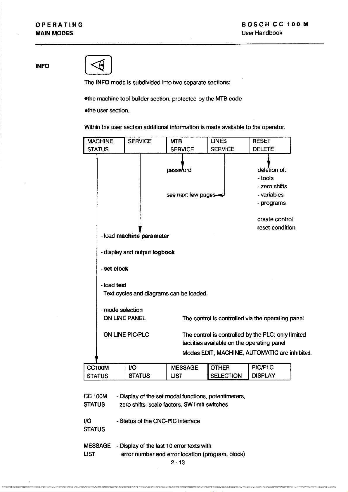
INFO (
<17
The INFO mode is subdivided
ethe machine toal builder section, protected
.the
Within the user section additional information is made available
MACHINE
STATUS
]
user section.
-load
machine
into!wo
SERVICE MTB
SERVICE
paSS\ol
see next
parameter
separate sections:
by
the MTB
LlNES
SERVICE
ord
lew
page~
code
to
the operator.
RESET
DELETE
deJion
tools
-
- zero shifts
-variables
- programs
create
reset condition
of:
control
- display and output
-set
clock
-load
text
Text cycles and diagrams can be loaded.
- mode setection
ON UNE PANEL The contral is controlled via the operating panel
LlNE PIC/PLC
ON
CC100M
STATUS
CC 100M
STATUS zero shifts, scale factors, SW limit switches
1/0
STATUS
1/0
STATUS
- Display
-Status
logbook
The control is contralled
lacilities available on the operating panel
Modes EDIT, MACHINE. AUTOMATIC are inhibited.
MESSAGE
LIST
01
the set modal lunctions. potentimeters,
of
the CNC-PIC interface
OTHER PIC/PLC
SELECTION DISPLAY
by
the PLC; only limited
MESSAGE
LIST error number and error location (program, block)
- Display
01
the last 10 error texts with
2 - 13
Page 45

OPERATING
MAIN
MODES
selection
BOSCH
User Handbook
CC
100
M
ce
100M
STATUS
I
TABLE
I
TABLE
Display
(Seperate
EXTERNAL
STATUS
MESSAGE
UST
lUST
I
lUST
01
machine status conditions, defined by
DNC
description
PAGE
in
preparation)
+
AXES
DISPLAY
I PAGE-
MTB.
PIC/PLC
DISPLAY
2 -
14
Page 46
OPERATING
MAIN MODES User Handbook
BOSCH
CC
100
M
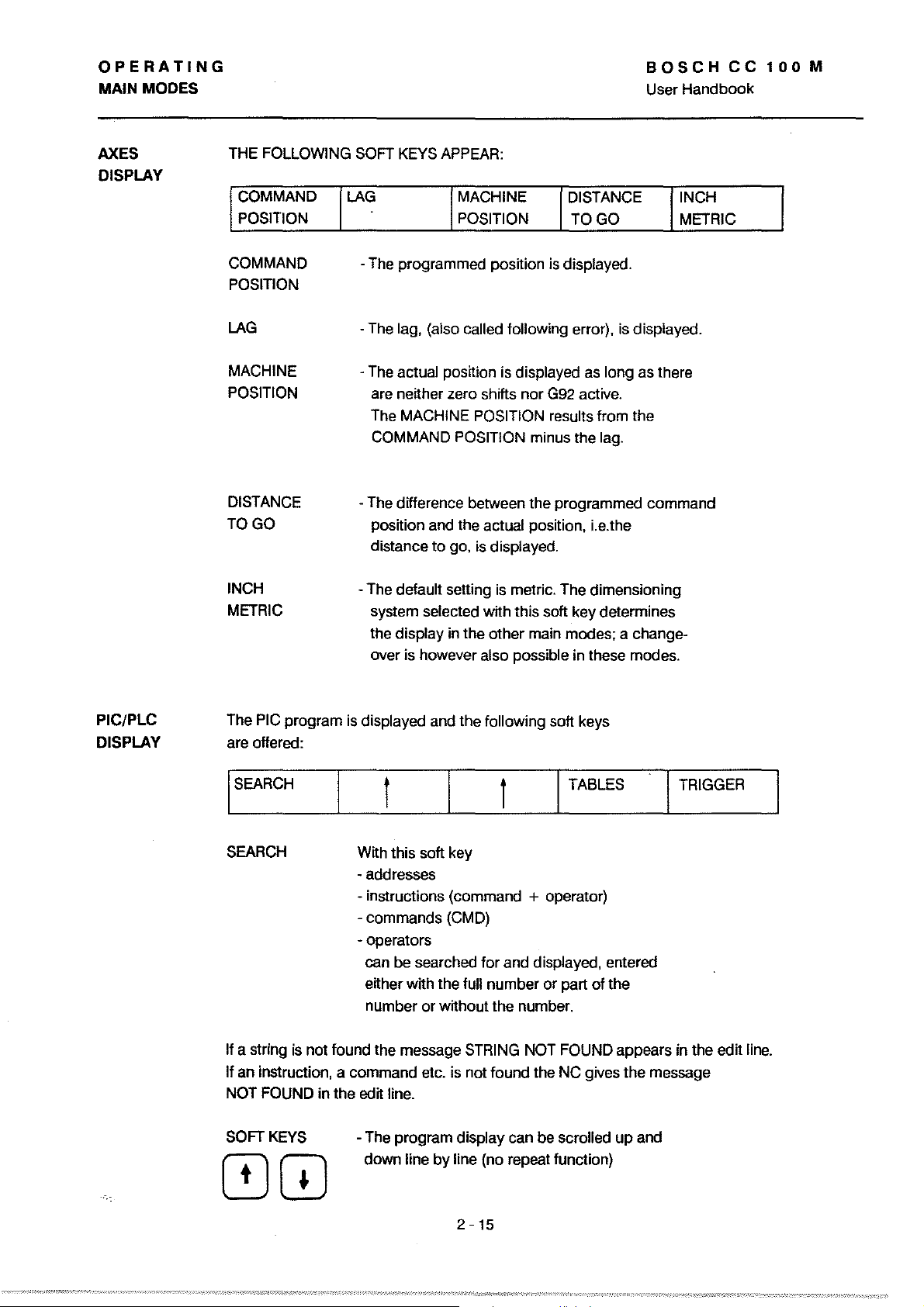
AXES THE FOLLOWING
DISPLAY
COMMAND
POSITION
COMMAND
POSITION
LAG
MACHINE
POSITION
DISTANCE
TOGO
INCH
METRIC
SOFT
KEYS
APPEAR:
LAG
-The programmed position
-The
lag, (also called tollowing error),
The
actual position is displayed as long as there
are
netther zero shifts nor
MACHINE POSITION results trom the
The
COMMAND
-The difference between the programmed command
position and the
distance
detault setting
-The
system
the
display in the other main modes; a change-
over is however
MACHINE
POSITION
POSITION minus the lag.
actual position,
to
go, is displayed.
is
metric. The dimensioning
selected wtth this soft key determines
also possible in these modes.
DISTANCE INCH
TOGO
is
displayed.
is
displayed.
G92
active.
i.
e.the
METRIC
PIC/PLC
DISPLAY
The
PIC
program
are offered:
ISEARCH
is
displayed and the tollowing soft keys
t
SEARCH
It astring
an instruction, a command etc.
It
NOT FOUND in the edit line.
SOFTKEYS
is
not tound the message
Wtth
this soft key
- addresses
- instructions (command + operator)
- commands (CMD)
- operators
be
can
etther wtth the tull number or part ot the
number or
-
The
program display can be scrolled up and
down
line
I TABLES
t
searched tor and displayed, entered
wtthout the number.
STRING
is
not tound the NC gives the message
by
line (no repeat tunction)
NOT FOUND appears in the edtt line.
TRIGGER
2
-15
Page 47
OPERATING
MAINMODES
BOSCHCC100M
User
Handbook
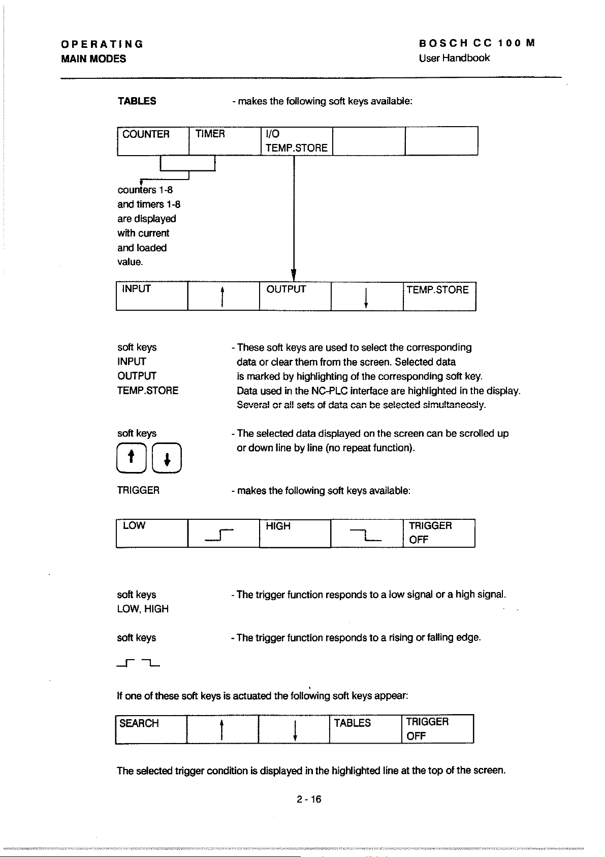
TABLES
COUNTER
I
courrters
and
are
with current
andloaded
value.
INPUT
soft
INPUT
OUTPUT
TEMP.STORE
1-8
timers 1-8
displayed
keys
TIMER
I
I
t
-
makes
-
These
data
is
marked
Data
Severa!
the
lollowing soft
1/0
TEMP.STORE
OUTPUT
soft
keys
are
or
c1ear
them Irom the
by
highlighting
used
in
the
er
all
sets
used
NC-PLC
of
data
keys
available:
TEMP.STORE
l
to select the corresponding
screen.
01
the
interface
can
SeleC1ed
corresponding soft
are
be
se!ected
data
highligh1ed
simu!taneos!y.
in
key.
the display.
soft
keys
00
TRIGGER
LOW
soft
keys
LOW,
HIGH
soft
keys
II
one
01
these soft
ISEARCH
keys
-
The
or down line
-
makes
-
The
-
The
is
aC1uated
t
selected data displayed on the screen
by
line
(no
repeat lunction).
the lollowing soft
I
HIGH
trigger lunction
trigger lunction responds to a rising or lalling
,
the lollowing soft
keys
available:
res
ponds to a low
keys
I
TABLES
appear:
can
I
TRIGGER
OFF
signal
or a high signal.
I
TRIGGER
OFF
be
scrolled
edge.
up
The
seleC1ed
trigger condition
is
displayed in the
2
-16
highligh1ed
line at the top
01
the
screen.
Page 48

OPERATING
MAINMODES
BOSCHCC100M
User
Handbook
The highlighted line at the
STATUS
SIGNAL TYPE as selected by soft key
-Iowlevel
- high level
-
-talling edge
top
01
the screen contains the lollowing information:
- watting
(signal has
- triggered
(signal has occurred)
rising edge
lor
not
occurred yet)
INSTRUCTION
ADDRESS
While the trigger lunction is
Soft key TRIGGER OFF swttches the trigger lunction off. The purpose
trigger lunction is the
tt
is an important aid
UNES SERVICE SOFTKEY
Unes
service
PORT
SETUP RESET
(separate DNC description in preparation)
UNE
I
I
-
instruction marked
address
-
monttoring
lor
lault finding.
FOR
DNC OPERATION
by
the cursor in the displayed program
01
the displayed instruction
swttched
on
tt
is possible
01
signals which
DNC STATUS
I
to
page through the program.
occur
intermittently;
DNC
MASK
ON
I I
01
the
OFF
I
2
-17
Page 49

OPERATING
MAiNMODES
DIMENSIONING - SWiTCHING BETWEEN INCH/METRIC
BOSCHCC100M
User
Handbook
MEMORY
TOOLS
!ACCESS
ON/OFF
ACCESS
ON/OFF
I TOOLS
mode
ZERO VARIABLES
SHIFTS
INCH
METRIC
I ZERO
I~~
PROGRAMS
I EDIT
EDIT LOAD
I VARIABLES !PROGRAMS
I LOAD
CYCLES
I SAVE
SAVE
! CYCLES
I SAVE
Effect:
ICOMMAND
e.g.l
I EDIT
IENTER I
I LOAD
I~~
I INCH
METRIC
can
not
be
VARIABLES
Whether the file types, tools and zero shifts are
effeetive in metrie
The file types program and eycles are stored with the
dimensioning index
switehed
or
inch is determined
11M.
Metrie is preset for
to
INCH/METRIC.
by
soft key.
new
to
files.
be
ISAVE
IRENAME
2
-18
Page 50

OPERATING
MAIN MODES
BOSCHCC100M
User Handbook
Effect:
MACHINE
In main mode MACHINE the INCH/METRIC swttching is effected in the first soft key line:
REFERENCE
AXES
The selection is effective for all functions in MACHINE mode.
The selection is retained even after a hardware reset and
also applies after a switch into INFO mode.
AUTOMATIC
File types such as programs and cycles are al ready defined
wtth respect
The chosen dimensioning method also
mode
REFERENCE MOl
CYCLE
mode
to
the dimensioning during the generation process.
applies for the execution.
TEACHIN
I INCH
METRIC
it
INFO
mode
The axis measurement format (INCH/METRIC) selected
sets the
MACHINE
STATUS
CC100M
STATUS
CC100M
STATUS
COMMAND
POSITION
priortty for the axis display
SERVICE
1/0
STATUS
1
EXTERNAL
STATUS
LAG
in
machine mode.
MTB
SERVICE
MESSAGE
LIST
MESSAGE
LIST
MACHINE
POSITION
LlNES RESET
SERVICE
OTHER
SELECTION DISPLAY
I
AXES
DISPLAY
DISTANCE
DISPLAY
in
INFO mode
IPIC/PLC
DELETE
I
PIC/PLC
DISPLAY
INCH
METRIC
- The desired dimensioning method is selected for the particular axis display
(command/position, machine
On switch-on the dimensioning method last active is reactivated.
-
posttion, lag, distance
2 -
19
to
go).
Page 51

OPERATING
DATA
I1ANDLING
BOSCH
User
Handbook
CC
100
M
GENERAL
LOAD / SAVE
DATA
The CC100M has
are located
The first interface, which is identified by the control as
"Port No.
interface, identified as
to
socket X
1",
!WO
serial data interfaces,
on
the CP/MEM board.
is connected
"Port No. 2", is connected
12.
to
HANDLING
socket X
the
11.
The second
sockets
1st
PERIPHERAL
V24/TTY Port
NO.1
50-9600 Bd
of
which
V24 Port
2nd
PERIPHERAL
and output
Input
EDIT. Interface selection and parameterisation are made via soft keys.
In main
mode
of
data is possible in main modes INFO and
"EDIT" the following types of data can be loaded and saved:
(soft keys:)
TOOLS ZERO VARIABLES PROGRAMS
SHIFTS
CYCLES
mode
In "INFO"
M-functions, texts and graphics.
Programs, tools, zero shifts and variables can only be cleared.
it is possible load machine parameters,
2-20
Page 52
OPERATING
DATA
HANDUNG User Handbook
BOSCH
CC
100
M
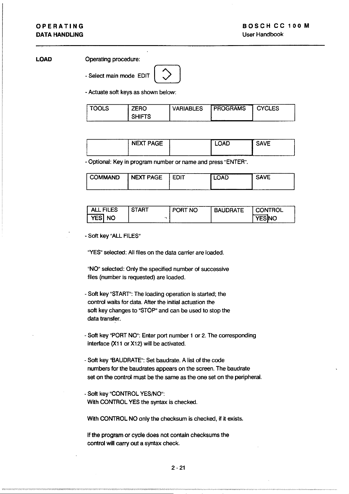
LOAD
Operating procedure:
Select
main
-
-Actuate soft
TOOLS
mode
keys
as
ZERO
SHIFTS
I NEXTPAGE
- Optional:
I
COMMAND I NEXT
ALL
YESI
Key
FILES
NO
in
program number or
START
EDIT
rn
shown below:
PAGE I EDIT
,
VARIABLES
name
and
PORT
NO
PROGRAMS
I
LOAD
press
"ENTER".
I
LOAD
BAUDRATE
CYCLES
I
SAVE
I
SAVE
CONTROL
YES]NO
- Soft
key
"ALL
FILES"
"YES"
selected:
"NO"
selected: Only
files (number
-
Soft
key
"START":
control waits for
soft key changes to
data transfer.
- Soft key
interface
- Soft
numbers for the baudrates appears
set
-
Soft key
With
"PORT
key
"BAUDRATE":
on the control
"CONTROL
CONTROL
(X11
All
files
the
is
requested)
The
data.
"STOP"
NO":
or
X12)
must
YES
on the data carrier
specified number of successive
are loaded.
loading operation
After the initial actuation
and
Enter port number 1 or
will
be
aClivated.
Set
baudrate. A list
be the
same
YES/NO":
the
syntax
can
be
on
as
is
checked.
are
is
started; Ihe
used
cf
the
screen.
the one
loaded.
the
to
stop the
2.
The
corresponding
the code
The
set
on the peripheral.
baudrate
With
CONTROL
If the program or cycle does not contain checksums the
control will carry out a syntax check.
NO
only the checksum
2 -
21
is
checked,
if
it
exists.
Page 53

OPERATING
DATA HANDLING User Handbook
BOSCH
CC
100
M
Nole Under
compensations, zero shifts and variables; the same applies
Cycles are loaded
When the last program
is stopped.
the data carrier loading
II the subsequent files are to
Protection
SAVE
When loading data via serial interfaces programs are automaticaJly
protected against overwriting.
a1ready
- overwrite the existing program
- store the program under a new number
- abort the loading operation
A program with overwrite protection can not
Error message:
Operating
SK
"PROGRAMS"
II there are tool, zero shift and variable files on
stored
in
the memory the control will ask whether
'1ile
procedure:
it
is
also possible
in
succession, like the programs.
or
cycle has been loaded the load operation
is
stopped after each lile, il an
be
loaded too
II a program is loaded wh ich
protected".
to
load cycles, tool
SK
(input
(input
(SK
be
EOT
"START"
overwrit1en.
must be actuated
1)
2)
"STOP")
lor
SK
"CYClES".
signal separates the Iiles.
lor
each one.
is
to
Select main mode
-
- Actuate soft keys as shown below:
TOOlS
- Optional: Key in program
ANOTHER
SELECTION
The screen displays the message "SElECTED
Soft keys
-
"START",
EDIT
ZERO
SHIFTS
I
NEXT
START
"PORT
VARIABLES
PAGE I lOAD
or
cycle name or number and actuate
PORT
NO
NO" and
"BAUDRATE"
PROGRAMS
BAUDRATE
FilE
ONlY"
are operated as
CYClES
"ENTER".
CHECKSUM
YES/INO
(highlighted characters)
lor
loading.
Soft key "CHECKSUM" switches the generating
which is
PROGRAMS
+ CYCLES
to
be
output, on and off.
START
FILE +
TOOlS
2
-22
01
achecksum,
FILE
+ I FILE + I
ZEROSHIFTS VARIABLES
T
Page 54

PERATING
nAHANDUNG
BOSCH
User Handbook
Soft key "PROGRAMS + CYCLES" determines whether only etther
programs
in the lirst
be
output. (Display wtth highlighted characters.)
The page back button resets the display
- Soft keys "FILE + TOOLS", "FILE + ZEROSHIFTS" and "FILE +
VARIABLES". When one
will be displayed in
or
cycles are to be saved, depending on the selection
SK line,
or
whether programs and cycles are
to
"SELECTED FILE ONLY".
01
these
is
selected the corresponding term
highlighted characters.
to
CC
100
M
lte
liane
of these soft keys is selected the parameters 'from" and 'ta" must be
or
defined. Unless this is done no page back
The parameter ranges are as
1
tools
zero shifts 54 variables 1 -
Only the numbers should be entered, not the associated letter
codes. The sequence
Output wtthout fiie seiection:
TOOLS ZERO
PROGRAMS+
CYCLES
-48;
lor
SHIFTS
INEXTPAGE
START
lollows:
inpute.g.: 1,7,14,15,16,23,44
59;
input e.g.:
99,
A -
Z;
the variables is numbers lirst, then letters.
54, 57,
input e.g. 7,9,10,25, 49,A,C,L,X
VARIABLES
PORT NO
other selection is possible.
58
PROGRAMS CYCLES
I LOAD
BAUDRATE
ISAVE
FORMAT
omment
elete
I CHECKSUM
YES NO
Soft key "PROGRAMS + CYCLES" offers the choice
programs
depending on the choice made in the lirst
During the output
the dimensioning unit "INCH"
Main mode
Operating procedure:
- Activate main
- Continue with soft key operation
MACHINE
STATUS
or cycles. Either programs
01
programs and cycles the selection
or
INFO
mode
(<a)
"INFO"
SERVICE
or
cycles are preselected,
"METRIC" is output in the program header.
MTB
SERVICE
2
-23
I FORMAT
softkey
DFS
line.
UNES
SERVICE
CC1DD
01
outputting
01
RESET+
DELETE
Page 55

OPERATING
DATA
HANDLING
BOSCHCC100M
User
Handbook
Caution
DELETE
TOOlS
The selected soft key is highlighted
The delete operation can be aborted with the page back button.
When the "ENTER" key is pressed
deleted, even those with write protection.
Delete lunction in main mode EDIT W
In main mode "EDIT" programs are deleted individually (or
cycles, depending
without read/write protection can
Operating procedure:
-
Select main mode "EDIT"
DELETE
ZEROSHIFTS
on
the soft key selection), and only those
DELETE DELETE
VARIABLES PROGRAMS
on
the display.
all programs will be
be
deleted in this mode.
CONTROl
RESET
Note
- Continue with soft
key
operation:
ZERO
SHIFTS
I NEXTPAGE
program
Select
ICOMMAND
COMMAND PROTECTION
II
an anempt is made
read/write protection the message
In "EDIT" mode it is
zero shifts.
or
cycle by name
I NEXT PAGE
ON
OFF
to
delete a program
not
possible
I EDIT
to
I VARIABLES
or
number.
INCH
or
'file protected" will appear
delete tool data, variable data and
PROGRAMS I
I
lOAD
I
lOAD
DELETE
cycle with
on
CYClES
I
I SAVE
I SAVE
IRENAME.
I
the screen.
2-24
Page 56
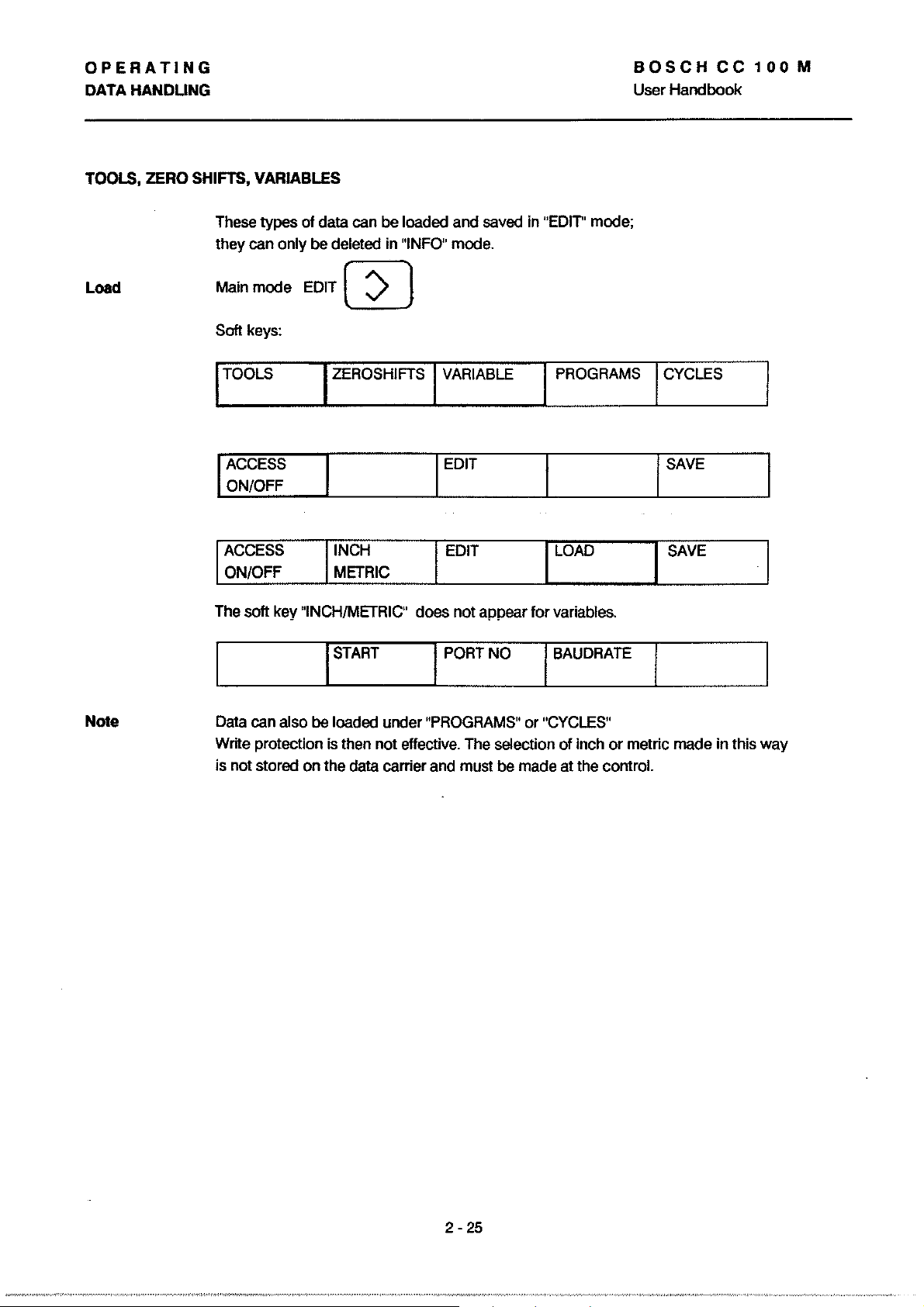
OPERATING
DATA HANDUNG
TOOLS, ZERO SHIFTS, VARIABLES
BOSCH
User
Handbook
CC
100
M
Load
These types
they can only be deleted in
mode
Main
Soft keys:
TOOLS ZEROSHIFTS VARIABLE PROGRAMS CYCLES
I ACCESS
ON/OFF
ACCESS
ON/OFF
The soft key "INCH/METRIC"
of
data can be loaded and saved in
"INFO" mode.
EDIT W
I EDIT
INCH
METRIC
I START
EDIT LOAD
does
not
appear
I PORT NO
"EDIT"
for
mode;
variables.
I BAUDRATE
I SAVE
SAVE
Note
Data can also
Write protection is then
is not stored
be
loaded under "PROGRAMS"
on
the data carrier and must be made at the control.
not
effective. The selection
or
"CYCLES"
of
inch
or
metric made in this
way
2
-25
Page 57
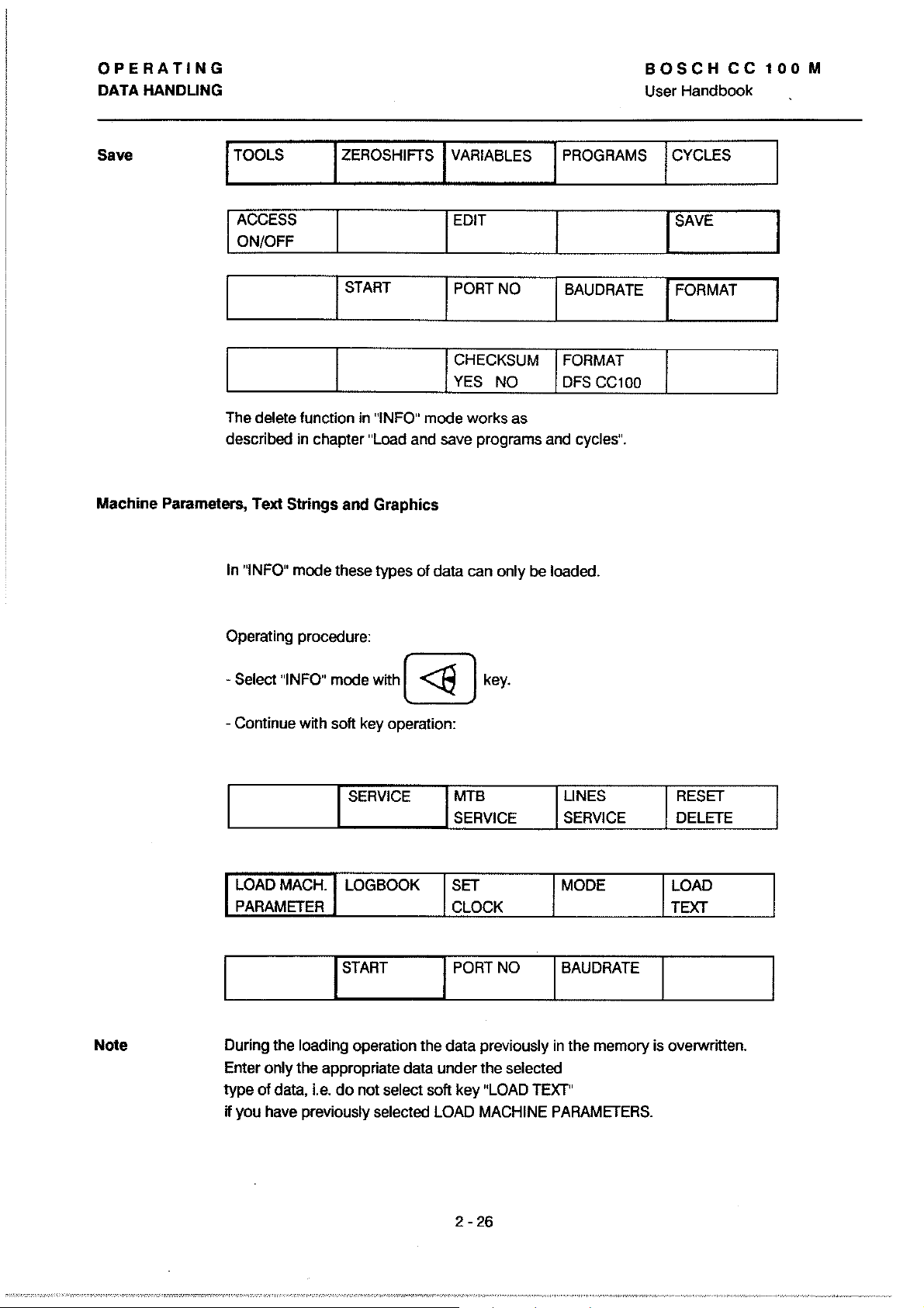
OPERATING
DATA HANDUNG
BOSCH
User Handbook
CC
100
M
Save
Machine Parameters, Text Strings and Graphics
I
TOOLS
I
ACCESS
ON/OFF
The
delete funetion
deseribed
In
"INFO"
mode these types
ZEROSHIFTS I VARIABLES
I
START
in
in
ehapter
"INFO"
"Load
mode works
and
of
IEDIT
I
PORT
I
CHECKSUM
YES
save
programs
data
ean
NO
NO
as
only
IPROGRAMS
I
BAUDRATE
I
FORMAT
.
DFS
and
eyeles".
be
loaded.
CC100
ICYCLES
I
SAVE
I
FORMAT
Note
Operating proeedure:
-
Seleet
- Continue
I
During the loading operation
Enter only the appropriate data under the
type of
H you
"INFO"
wtth
LOAD
MACH.
PARAMETER
data.
Le.
have
previously
mode
wtth
(
-<a
soft keyoperation:
SERVICE
LOGBOOK
I
the
data previously
do not
seleet
seleeted
soft key
LOAD
)
key.
MTB
SERVICE
SET
CLOCK
PORT
"LOAD
MACHINE
NO
seleeted
TEXT"
UNES
SERVICE
MODE
I
BAUDRATE
in
the memory
PARAMETERS.
IRESET
DELETE
LOAD
TEXT
is
overwrttten.
I
2
-26
Page 58
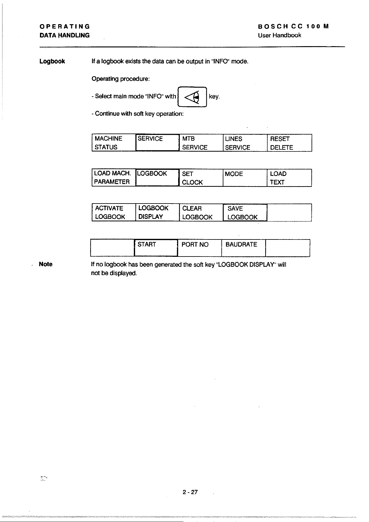
OPERATING
DATA
HANDLING
BOSCH
User
Handbook
CC
100
M
Logbook
II a
logbook
Operating procedure:
Select main mode "INFO"
-
- Continue with soft key operation:
MACHINE SERVICE
STATUS
LOAD MACH.
PARAMETER
ACTIVATE
LOGBOOK DISPLAY
exists the data can
With@]
LOGBOOK
LOGBOOK
be
I MTB I LlNES
output in "INFO" mode.
key.
RESET
SERVICE SERVICE
SET MODE
CLOCK TEXT
ClEAR
LOGBOOK LOGBOOK
SAVE
DELETE
LOAD
I
. Note
II no
logbook
not
be displayed.
I START I PORT NO
has been generated the soft key "LOGBOOK DISPLAY" will
I BAUDRATE
2
-27
Page 59

3.
PRO
G R A M M I N G
Page 60
PROGRAMMING
General
Program Production
GENERAL
BOSCH
User
Handbook
CC
100
M
Memory
Allocation
Part programs can
- directly
-
at
The loIlowing
Memory areas
part program
techno!ogy
at
the
control via
programming stations
types
memory
tab!e
be
produced
01
user data are stored in the controI:
by
the lollowing methods:
panel input in modes EDIT
MACHINE (TEACH IN)
Fortransmissions
the instructions in seetions:
DATA
INTERFACES (chapter 1)
Data
handling (chapter
Contents
part programs and cycles,
with the relevant subprograms
tool
geometry
cutting speeds
please note
and
tool
or
2)
wear
or
data,
Basic Conditions
zero s h i I t table
variable table
machine parameter
Descriptions in
the control as used on a machine tool (milling machine)
with a Cartesian axis conliguration within a clockwise
coordinate system.
G-Iunctions are assumed
memory
the
programming instructions relate
Unless otherwise stated the
to
be
active:
G17
G27
G40rrOO
G53
G62
G90
zero shifts G54
CPC varables
machine specific data
planeXY
no
field limitation
no
tool
compensation
no
zero shift active
in position function off
absolute dimensions
VI-V99 and VA-VZ
to
lollowing
to
G59
The reset status
mode
is indicated
or
the
status after switching
by'A'.
3 - 1
to
automatie
Page 61
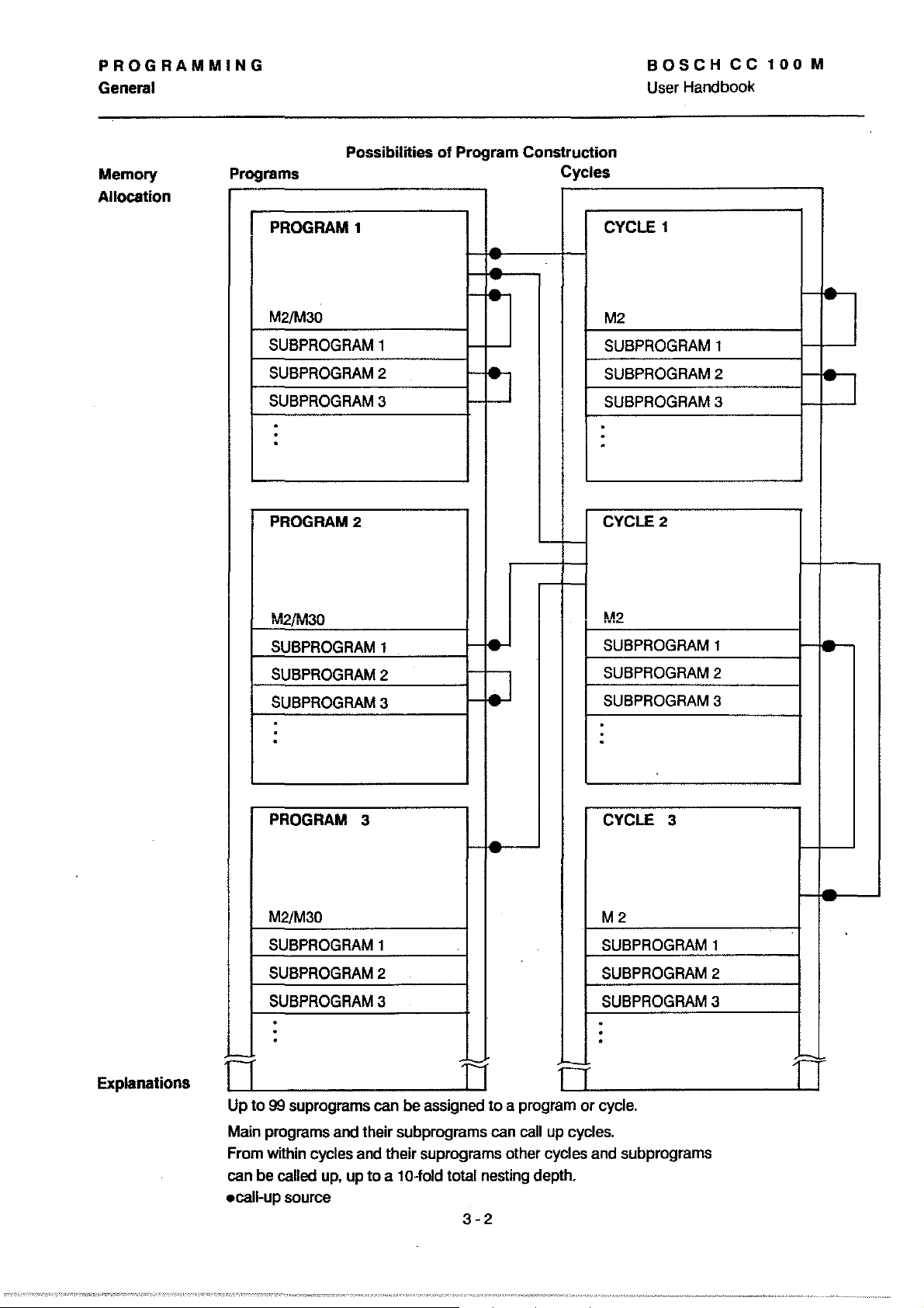
PROGRAMMING
General
BOSCH
User
Handbook
CC
100
M
Memory
Allocation
Possibilities
Programs
PROGRAM 1 CYCLE 1
01
Program Construction
Cycles
-
M2/M30
SUBPROGRAM
SUBPROGRAM
SUBPROGRAM
·
·
·
PROGRAM2
1
2
3
-
M2
SUBPROGRAM
SUBPROGRAM
SUBPROGRAM
·
·
·
CYCLE 2
2
3
1
'-
-
-
Explanations
M2jM30
SUBPROGRAM
SUBPROGRAM
SUBPROGRAM
·
·
·
PROGRAM 3 CYCLE 3
M2/M30
SUBPROGRAM
SUBPROGRAM
SUBPROGRAM
·
·
·
=
o
Up
to 99 suprograms
r-
";:,..
fe-
1-
2
3
1
2
3
1
.
TI
can
be assigned 10 a program or
M2
SUBPROGRAM
SUBPROGRAM
SUBPROGRAM
·
·
·
M2
SUBPROGRAM
SUBPROGRAM
SUBPROGRAM
·
·
·
-
D
cycle.
1
2
3
2
3
1
-
-
=
n
-
Main
programs
From within cycles
can
be
called
ecall-up source
and
up.
their subprograms
and
their suprograms other cycles
up
to a 10-fold total
can
nesting
3-2
call
depth.
up
cycles.
and
subprograms
Page 62

PROGRAMMING
General
PART
PROGRAMS
AND
CYCLES
BOSCH
User Handbook
CC
100
M
Block
Word
A program
and is subdivided into
lunctions, axis inlormation, miscellaneous and auxiliary lunctions.
A block is made up
Example: N120
or
a cycle describes a sequence
blocks. The blocks contain preparatory
01
the block number and one or several words.
GO
X100
Z100
M3
01
machining operations
S1000
TT=rTT:T
block number words
The
block length
words can be wrilten in any order. The
the beginning
blocks. But note the gap between the block number and the lirst
word (see transmission protocol,
A word consists
which represent the address contents.
Only those ligures which contain inlormation need be wrilten.
N10
GO
Nl0
GO
is
variable. During external programming the
block number must be at
01
the block. No space characters required between
p.
3-4).
01
an address letter and a sequence olligures,
X5.100
X5.1
ZO.500
Z.5
M3
M3
Tm
TOl
or
Block
Numbers
- sequence
steps
-
Blocks
Example:
With
The lirst word
It is made up
a
During
to
During
automatically
Block numbers are programmed
I!
will mark these blocks with a " +
The
deletions sine they are marked with symbolic "labels".
are built
DIN programming
110
4-digit sequence
external
be programmed. The control will store data in ascending order.
panel
additional blocks are entered via
up
lrom
individual words which begin with
.Lr--l.----,l------
N
120
X 125 Z
11...
__ 1'-_1-'-
01
a program block is the block number.
01
the address letter
program production no block numbers need
160
_____
an
address may only be programmend once in each block.
"N"
(ISO
of
ligures.
address
address content
lormat) and
input the control generates the block numbers
in
the course of the input dialogue.
or
generated in steps
"INSERT"
the control
of
an
1.
".
jump
addresses remain valid after insertions or
address letter.
3-3
Page 63
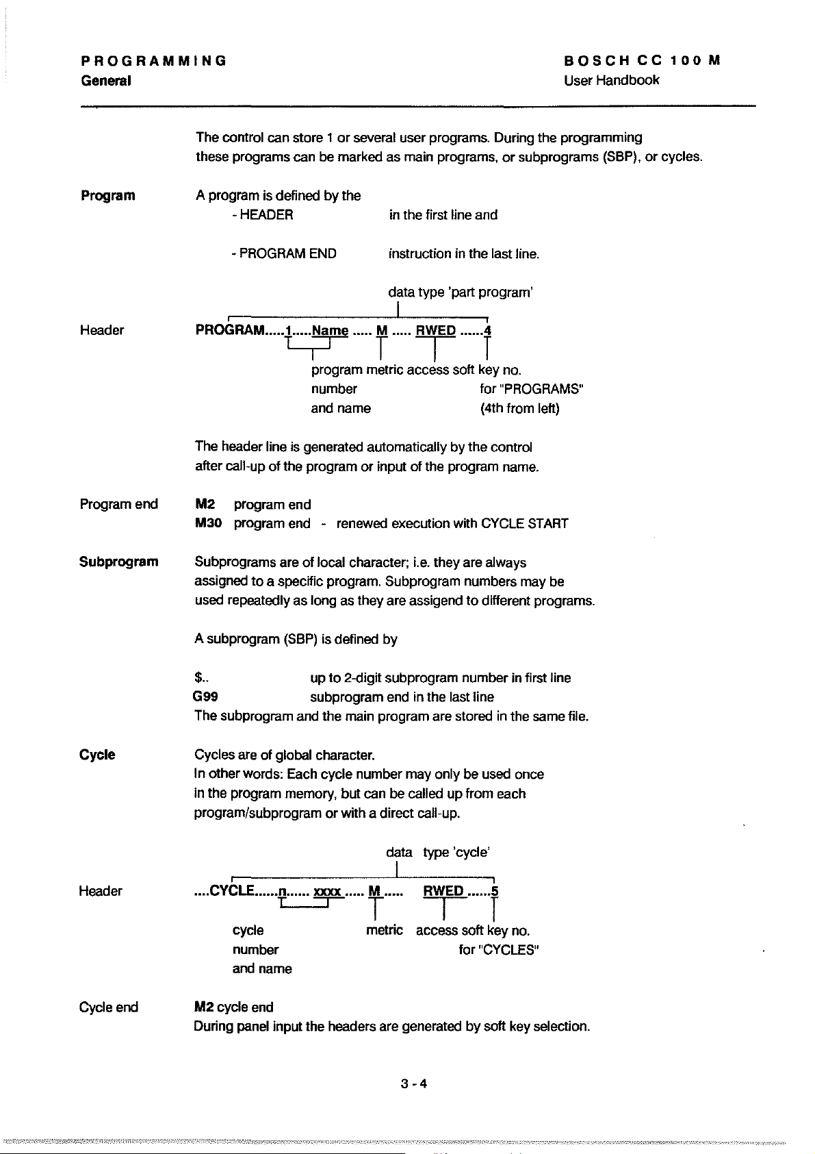
PROGRAMMING
General
or
The control can store 1
these programs can be marked as main programs,
several user programs. During the programming
BOSCH
User Handbook
or
subprograms (SBP),
CC
or
100
eyeles.
M
Program
Header
Program end
Subprogram
A program is deHned
-HEADER
- PROGRAM END instruetion in the last line.
by
the
in the lirst
data type 'part program'
line and
I
PROGRAM"
The header line is generated automatically by the eontrol
after
caJl-up
M2
M30 program end - renewed exeeution wtth CYCLE
Subprograms are
assigned
repealedly as long as Ihey are assigend
used
••
t-,,,~
program melrie aeeess soft key no.
number
and name (4th
01
the program
program end
ollocal
to
a speeifie program. Subprogram numbers may be
...
" T "
...
or
input
eharaeter;
T
01
i.e.
......
t
lor
the program name.
they are always
to
different programs.
"PROGRAMS"
lrom
left)
START
Cycle
Header
Cycie end
(SBP)
A subprogram
$"
G99
The subprogram and the main program are slored in Ihe same lile.
Cycies are
In other words: Eaeh eyele number may only
in the program memory, but can be
program/subprogram
""CYCLE"""-?"",,
01
global eharaeter.
I
is defined
up
to
subprogram end in Ihe last line
or
~"'"
by
2-digit subprogram number in lirst line
be
used onee
ealled
up
Irom eaeh
wtth a direet call-up.
data type 'eyele'
I
T"'"
RWED
i
".".5
T T
eycie
number
and name
M2
cyele end
During panel input the headers are generated
melrie access soft key no.
lar
"CYCLES"
by
soft key selection.
3-4
Page 64

PROGRAMMING
General
BOSCHCC100M
User Handbook
Jump
Instructions
Program jumps can
the individual program segments.
The jump instructions relate to jump addresses (labels)
which are
are retained even when program alterations are carried out
by
inserting
Programming
to
be previously delined. These symbolic addresses
or
G24 P x x (unconditional jump)
be
used
deleting blocks.
01
lor
a more efficient usage
01
or
G23 P x x (conditional jump)
= jump address number
P
effects branching to a program line
which
is
marked as a jump address:
$ xx.
Example
SBP Call-ups
Nl0
Nl1
$ 2
::Y~J
N21 N ..
N22
N24
N25
The calling up
.
Y
..
.
X
...
G24
P2
01
subprograms must only be possible by programming
P .. L.. unconditional
G22
G21
P
•.•
L.. conditional
SBP
=
SBP
P
L = repetition 0 .... 99
number 1
sequence if
signal OPITIONAL JUMP = high:
SBP
call-up
call-up
Nl010
sequence il
signal
Nl0
N20/
Nll
to
OPTIONAL JUMP = low:
10
N25 /
Nl1
10
N25.
or
to
99
N20
For this reason the subprogram call-ups G21/G22 in the
be
main program must
themeselves
by
M2/M30.
separated Irom the subprograms
SBP
One
places within the relevant main program.
can be called up repeatedly and Irom different
3-5
Page 65

PROGRAMMING
General.
Example
Main program
and sub-
program must
be separated
by
M2/M30
Nl0
G22
N22G21
P5
P5
BOSCHCC100M
User Handbook
L2
2 passes
A
--
---
Subprogram
Decisions
N30M2
N31
$5
N32
2nd pass
Nl0
N40G99
Subprogram
The jumps
Theyare not carried out (and the program is continued
the next line)
-
caUs
or
jumps can be linked
-the logic state
- the result
(parametric lunctions)
or
caUs
are carried out if the stated condition is fulliUed.
if
the condition is not lulliUed.
return
to
a condition, which can be
01
interface contacts
01
a mathematical comparison
or
at
3-6
Page 66

PROGRAMMING
General
PARALLEL PROGRAMMING
BOSCH
User Handbook
CC
100
M
Definition Parallel programming allows the control
Functions
Tables
mode while an active program
In edit mode tool data, zero shift tables, variables and part
programs can
Active programs and cycles can not be edited in
PARALLEL
available
TOOL, ZERO SHIFT and VARIABLE lables can be edited, entered and
output. Contents
active program can not be edited in
A possibility does, however, exist
during program execution. After the program has been completed
the existing lable
(updated). The control generates a passive table tor this purpose.
be entered, edited and output.
PROGRAMMING
editing, input and
output in
EDITmode
in
Parallel Operation
01
tables which need
is
overwritten with the modilications
is
being executed.
simullaneously
parallel operation.
to
edit table contents
to
be used in EDIT
parallel operation.
to
be accessed by the
AUTOMATIC
execution
part programs
01
output
ACTIVE
TABlE
.J
access
ACTIVE PROGRAM
.-
-1
I
~
!A":>SIV~T~lE
--1
I I
I EDITING I
I POSSIBLE I
I
~
3-7
Page 67

PROGRAMMING
General
BOSCHCC100M
User
Handbook
CYCLES
PROGRAMS
Soft key
TABLES
Cycles can not be edited in parallel operation. But they
can be input and output via the serial interface.
Programs can be edited in parallel operation and can also
to
be input !rom and output
active
The
There
program in the memory belore starting program execution.
The copied program can then be edited.
During
operation the soft key T
Under this soft key it is possible
TOOlS,
01
out
program can not be edited.
is,
however, the possibility
AUTOMATIC execution
ZERO SHIFTS and VARIABLES without having
main mode AUTOMATIC.
external data carriers.
01
copying the active
01
a program while in parallel
ABlES
appears.
to
look
at the tables
to
come
3-8
Page 68

PROGRAMMING
General
BOSCHCC100M
User Handbook
DRIP
DEFINITION
DRIP FEEDING - SINGLE ACTIVATION
DRIP
FEEDING
DRIP FEE DING - CONTINUOUSL Y ACTIVE
IACTIVEONI
'pOWER ON,
FEEDING
Long programs which
can be loaded via interface
drip
Single
IN AUTOMATIC mode (direct selection).
II
drip
AUTOMATIC mode is selected the operator must switch
leeding operation is activated via soft key
leeding is
do
to
be activated automatically when
not fit into the program
lor
direct execution.
memory
to
(reverse video) in the 3rd soft key level (INFO mode).
DRIP FEEDING - USER INTERFACE
In AUTOMATie mode the preset parameters
Example
will
START
appear
on
the display once it is activated.
BLOCn
POPT
BHUD
OFFSET:
:;IZE
~
110:
RH
TE
OF
BUFFEP
1
24(l1)
12
:
lor
DRIP FEEDING
512
IIE>:T
PAGE
I
PF:OGPHIE.
C,,.CLES
3-9
Page 69

PROGRAMMING
General
The
DRIP
FEEDING parameters are preset in INFO mode.
The parameters
do
not affect the pragram which is
to
be executed.
BOSCH
User Handbook
CC
100
M
Meaning
ACTIVEON
POWER ON
BUFFER
SIZE
01
Main mode
MACHINE
STATUS
INFO
SERVICE
MTB LlNES
SERVICE
I DRIP
FEEDING
ACTIVEON
POWER ON
the
DRIP FEEDING parameters
If
this parameter
defaults to
The BUFFER SIZE parameter determines the buffer size in
0.5 kBytes, which is to be kept free
the part program memory of the
nput format: 512 bytes
I
Min. buffer size: 1
Max. buffer size:
BUFFER
SIZE
is
active (reverse video) the control
DRIP
FEEDING mode when AUTOMATIC
(;
512 bytes)
.:s.max. available memory capacity (see
Drip Feeding and main memory)
PORT NO.
for
DRIP
contral.
SERVICE
BAUDRATE
is
selected.
FEEDING in
RESET
DELETE
BLOCK
OFFSET
IpORTNO.
IBAUDRATE
Selection of the interface on the CP/MEM
1 -V.24/20 mA (with handshake)
Port
Port 2 -V.24
Setting of the baudrate.
following baud rates are recommended (-1800 Bd):
The
(with or without handshake)
8 ; 1800Bd
;
2000Bd
9
10
;
2400Bd
11
;
3600Bd
12
;
4800Bd
13
;
7200Bd
14 ;
9600Bd
3
-10
Page 70

PROGRAMMING
General
BOSCHCC100M
User
Handbook
BLOCK
OFFSET
START POINT? Input
This parameter is originally preset so that the program
execution begins after
The setting
the execution is
Possibilities: n =
(1
= beginning
NC blocks before the start point are ignored.
"n" determines after
to
n 0
n > 12
of
the
block
number at which DRIP FEEDING is
01
12 program blocks have been loaded (min.).
how
rnany loaded blocks
begin.
-1
the program).
execution begins when the
lull
or
buffer is
is transferred
FEEDING
Execution begins when
blocks
Execution begins when the
specffied
blocks are loaded.
are loaded.
when M30/M2
Irom
program.
number
the DRIP
12 program
(n)
01
program
to
start
Note:
The
DRIP FEEDING parameters can only be changed
mode. Port no. and baudrate are independent
parameters
as
described in chapter "Data Handling".
01
the
in
INFO
3 -11
Page 71

PROGRAMMING
General
BOSCH
Handbook
User
CC
100
M
DRIP FEEDING AND
Part programs and
part program memory; the remaining
is used
When
in
mode the control checks whether the selected buffer size
exceed the available storage capacity. II it does an error message
will be produced. II the buffer size is not delined the user can utilize
the max.
Input:
II
there are
- deletion
MAIN
MEMORY
cycles
occupy
lor
DRIP FEEDING.
the
buffer size
INFO
mode
available storage capacity.
available
the
available storage capacity is
two
possibiltties:
of
individual programs
the available storage capacity
lor
DRIP FEEDING has been determined
and DRIP FEEDING is activated
storage capacitv
512
a certain area in the
available storage capacity
in
AUTOMATIC
(see basis display
AUTOMATIC)
in
not
sufficient
or
cycles
to
increase
does
not
INFO
- reduce the buffer size in
PROGRAM EXECUTION WITH DRIP FEEDING AFTER
The DRIP FEEDING operation is started wtth Cycle Start.
During program execution only the active
I DRY RUN
RAPID
By actuating SK
block can be listed.
Program execution is possible wtth the lollowing options:
- step size in program
- rapid
I
dry
I STEP
UST
run
01
the 6 blocks loIlowing the active
the program
mode
CYCLE
block
START
is displayed on the screen.
I TABLE
- starting the program at a set start point
3 -
12
(block N)
Page 72

PROGRAMMING
General
Recommenclations for achieving fast data input with drip feeding
BOSCH
User
Handbook
CC
100
M
- When the
or
FEED HOLD active) it loads
It
is
be
"live" on
where
the
minimum
cycle
- Drip teeding
Drip teeding programs should
with checksum in
transmission. Also the baudrate should not
control
therelore advantageous
as large as possible. The
data
the
block
loading
number
time will then be
has "some time" (e.g.
trom
the
buffer
cycte
time
ot
new
blocks is inhibited until
01
blocks
the
and
checksum:
order
to
same
increase
long
data
into
the
to
choose
control
tor
those
is critical. In this case
are
in
be
the buffer
is then able
program
the
buffer. The
as
when
translerred
the
speed
only
working
be
1800.
Position and calculation
(see program header in DFS format. page 1-22
of
the checksum
traversing path. G4 active.
buffer.
to
to
parts
the
block
trom
memory.
to
the
control
01
the
below
Restrictions
- Jumps. subprograms and
not
permitted in DRIP FEEDING programs;
- Parallel programming is not possible since there are
several functions active simultaneously
DRIP FEEDING:
- automatie program execution
block
-
- transfer function
- The REENTRY function is
processing
the
trom
not
setting
external
possible.
of
stop
points are
during
data
carrier (LOAD. SAVE)
3
-13
Page 73

PROGRAMMING
ADRESSES
ADDRESSES
BOSCH
User Handbook
CC
100
M
ADDRESS
Gl F
..
G2 F ..
G3 F ..
G5 F ..
G04F
..
G93F
..
G94F
..
G95F
..
F
F defines the path feedrate
as
dweil
F takes ellect
F takes effect
path section in seconds.
F takes effect
on switch-on.
Programmable
F takes effect
The
programmed
actual
speed
G95
is
uSed
as
as
range:
as
of the
lor tapping
in
execution time tor the pragrammed
teedrate
FO.OOl
feedrate
path
feedrate
main
and
in
mm/min.
seconds.
in
mm/min.
to F 50
in
mm/rev.
is
spindie.
linishing.
G94
is
active
000
derived fram
the
ADDRESS
T
CONTROL
T determines the tool number. which
and/or the
intemally.
T
..
L
II T is programmed with only 2 digits
interpreted
RESET
toollength compensation. which
T is programmed with 2 or 4 digits.
"t--
__
as
clears any programmed
tool number to
tothe
PIC
programmable range: 0 to
compensation graup
technology memory
pragrammable
the
compensation graup.
be
output
01
to
range: 0 up
is
to
the
be
applied
these
F-address.
be
output.
is
99
to
max.
are
to
be
48
always
applied
The
operation
is
described in detail under TOOL
01
the toollength and tool radius compensation
COMPENSATION.
3
-14
chapter
5.
Page 74
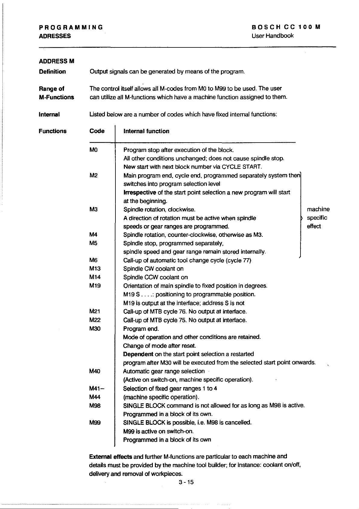
PROGRAMMING
ADRESSES
ADDRESSM
Definition
Range
M-Functions
of
Output signals can be generated
The
control itsell allows all M-codes
can utilize
all M-functions which have a machine
by
means
Irom
01
the program.
MO
to
M99
to
be used. The user
lunction
assigned
BOSCHCC100M
User
Handbook
to
them.
Internal
Functions
Usted below are a
Code
MO
M2 Main program end, cycle end, programmed separately system then
M3
M4
M5
M6
M13
M14
M19 Orientation
M21
M22
M30
M40
M41M44
M98
M99
number
Intemal
Program stop after execution
other conditions unchanged; does
All
New start with next
switches into program
Irrespective
at the beginning.
Spindie rotation, clockwise.
A direction
speeds
Spindie rotation, counter-clockwise, otherwise
Spindie stop, programmed separately,
spindie speed and gear range remain stored internally.
Call-up
Spindie CW coolant on
Spindie CCW coolant
S
....
M19
M19 is
output
Call-up
Call-up
Program end.
Mode
cf
Change
Dependent
program after
Automatic
(Active
Selection
(machine specific operation).
SINGLE BLOCK
Programmed in a
SINGLE BLOCK is possible, i.e. M98 is cancelled.
M99 is active
Programmed in a
01
codes
which have lixed internal lunctions:
function
01
the block.
not
cause spindie stop.
block
number via CYCLE START.
selection level
01
the start point selection a
cf
rotation
or
gear
01
automatic tool change cycle (cycle
01
main spindie
: positioning
atthe
01
MTB cycle 76.
01
MTB cycle 75.
operation and other conditions are retained.
cf
mode
on
the start point selection
M30 will be executed Irom the selected start point onwards.
gear
on
switch-on, machine specific operation).
cf
fixed
on
must
be active when spindie
ranges are programmed.
on
to
fixed position in degrees.
to
programmable position.
interface; address S is
No
output at interface.
No
output at interface.
after reset.
range selection
gear
ranges 1
command
block
01
switch-on.
block
01
to
is not allowed
its own.
its own
arestarted
4
new
program will start
as
M3.
n)
not
lor
as
long
as M98 is active.
machine
specific
effect
1
Extemal
details must be provided
delivery and removal
effects
and further M-Iunctions are particular
01
by
the machine tool builder;
workpieces.
3 - 15
to
each machine and
lor
instance: coolant on/off,
Page 75

PROGRAMMING
ADRESSES
ADDRESS S
BOSCH
User
Handbook
CC
100
M
Definition
G92 S
M19 S
S
.....
..
..
.
Definition
Programmed
speed,
When programmed in
the
limits
The spindie is oriented
If M 19 is programmed
parameter
Spindie speed in rpm. The direction
on
its
own
or
the
position
maximum speed
111
will
apply
the
S-address determines
for
spindie orientation.
conjunction
of
the
main spindie.
onto
the
position programmed with S (degrees).
on
its
own
as orientation point (range 00 - 359.999").
SPINDLE SPEEDS
Inputs are evaluated as folIows:
With G 97 S = spindie speed
The direction
the
programming
Minimum and maximum speeds
particular machine (M-parameters).
of
rotation must
of S or
directly
be
determined together with
belorehand.
are
with G92
the
of
predetermined
the
value defined
rotation (M3/M4)
in rpm format 4.3
the
spindie
S-address
by
machine
must
lor
the
have been defined.
ADDRESSM
Fixed
Selection
GEARRANGES
Machines with a
One particular gear range is programmed in
M41-44 with
The control assists with
idling speeds,
If a speed is programmed which
the
Automatie
Selection
M40
When M40 is active
appropriate gear range
-
up
output
1
to
-
when
automatically selected, on the basis of
- where gear ranges overlap
lower
gearbox
M41
to
44, corresponding
by
the
control outputs
to
4 gear ranges with min.
range
for
the
9999 rpm (MTB can restrict
S is programmed
of
any
two
possible gear ranges (higher
which can
the
change-over between
processing
the
max.
the
control itsell selects
on
the
speed:
the
be
controlled via
the
to
gear
ranges 1
of
signals relating
is
not
achievable within
or
min. speed possible within that range.
the
basis
of
the following criteria:
and
max. speed values can be controlied
the
range
for
appropriate gear range is
the
current
the
control
selects
the
CNC
user
program
to
4:
gear
ranges
to
the
gear
the
selected
the
particular machine)
program
the
motor
data
speed).
can
operate in
by
the
output
ranges etc. .
gear
range,
two
01
ways:
G9S + M40
A
new
gear range is only selected
achieved in
correct gear range has
the
active gear range. Idling speed
for
the
not
been acknowledged.
3 -
16
following
is
block
output
if
the
required speed can
for
as
long
as
the
activation
not
of
be
the
Page 76
PROGRAMMING
ADRESSES
BOSCH
User Handbook
CC
100
M
H-ADDRESS
Definition
Use
Programming
Hxx
Hxxxx
H-address = "FL
As
opposed
traversing movement, the H-address is output simulaneously
with the traversing movement.
This simultaneous output prevents drops
This function can used in programs tor machining operations
during which any momentary stopping of the axes would result in
damage to the workpiece (tor instance during laser cutting).
4-digit auxiliary tunction permits additional control and
This
switching tunctions tor time-critical applications.
-The H-address should be regarded
auxiliary tunction; it should not be programmed with
other auxiliary functions
-
The
programming format is up to 4-digit.
- Variables can be allocated to the H-address
N1
= 1:>1:>' H =
..
- -
----,
YING
OUTPUT"
to
the M-address, which
in
the same block.
V1\
- - -
"'-
is
output betore each
in
the command value.
as
an additional
Output
Note
The H-address is output to the interface
I! the address has 4 digits the last two are output tirst.
H-addresses can also be used tor the extension ot certain
(e.g.
tunctions
51 = 1000
speed programming
rpm; H =
500
rpm).
in
BCD
code.
in
dual spindie operation:
3
-17
Page 77

PROGRAMMING
ADRESSES
OPERATOR INSTRUCTION PROGRAMMING
BOSCH
User
Handbook
CC
100
M
Definition
Programming
Usage
Example:
The operator instruction
display
These texts can
give instructions
The contents
or
The text is programmed in brackets and must be written in
a separate block.
This facility can be used
Since the display always shows the next
execution while the program is being actioned it is
possible
MO
If a
an operator instruction, it will
this
of
texts
during
be
to
of
the
machine functions in any way.
to
put message
beforehand.
program
way
block
blocks
can
programming
the
program
purely informative
the
operator.
texts
do
not
to
provide documentation
up
on
the screen
is programmed in brackets,
not
be
blanked
out
facility allows
execution.
or
they
allect the
be actioned. In
program
block
by
in a program.
the
can
sequence
for
the
to
be
programming
Le.
as
program.
N5
N6
N7
MO
N8 (NOTE - SWITCH ON COOLANT
N9 X
... Y ..
Nl0X
... Y ..
The
program
The operator instruclion will then
.
.
sequence
stops
in
block
be
7 (due
displayed.
to
MO).
3 -
18
Page 78

PROGRAMMING
TABLES
Tools
TABLES
Up
to
48 tool compensation stores are available.
Each tool compensation store comprises
T1
R = uuu.uuu
DR
= u.uuu
I
tool
T
T
no. tool radius
or
(mm
Input dimension defined
inch)
wear
max.10%
radius, max.
1 mm, increm.
as
metric
of
input
or
inch via soft key.
the
following:
L =
T
toollength
(mm
UUU.UUU
or
inch)
BOSCH
User
Handbook
S =
uuu
T
cutting speed
or
m/min
inch/min
CC
100
M
Example:
Zero
Shifts
Example:
Variables
*****TOOL*************************************l*************
Tl
6 zero shifts are available (G54-G59). See under section "G-Functions"
Each zero shift comprises the
G54
I
nO.of
zero shift offset
The dimension is defined
**ZERO*SHIFT**********************************2*************
G54
A maximum
variable programs
Variables
R=
16.0
* = space character
DR=
0.9
following:
L=
G53,G54-G59
25.0
for
definition.
S=
10.0
x - uuuu.uuu Y - uuuu.uuu Z - uuuU.uuu E - uuuu.uuu
amount
X=
10.0
of
represent numbers
of
--,--I
_1'-------'--1
as
metric
125 variables are available
(V1
...
V99 and VA
Y=
of
or
inch via soft key.
20.0
...
up
to
7 digits.
for
the writing
VZ).
Z=
30.0
of
_----'I
E=
40.0
Example:
Header
line:
***VARIABLE***********************************3*************
V1 = 116.0
When programming tool data, zero shifts, variables, programs, cycfes
and
(M)
parameters externally, identifying HEADERS
as
shown above must be provided. These
a specific format which is explained
V2 = 8.0
3
on
page 1-17.
-19
V3 = 0.6
must
be written in
V4
=-1.0
Page 79

PROGRAMMING
G - FUNGTIONS
G-FUNCTIONS
BOSCH
User Handbook
CC
100
M
Definition
Feedrate
Interaction
Programming
Path
LINEAR INTERPOLATION IN RAPID
The axes travel
interpolation. The speed is determined
No
feedrate should be programmed (address
parameter values for rapid will become ellective.
This mode remains
GO
cancels modes GI,
Execution
"IN POSITION". THE IN POSITION range
are
Positioning with
GO
X..... Y.....
Programmable with
The traversing movement
for
the individual axes are different, or if the axes have different rapid speeds.
The override potentiometer can be deactivated for
AUTOMATIC
to
the programmed position with linear
modal until a different mode of motion
2,
01
the next block
GO
is
possible when the main spindie is stopped.
z......
or
without axis addresses.
by
machine parameter.
by
machine parameter.
F).
3 and
5.
is
not started until all axes
is
delined by machine parameter.
E ......
is
linear even if the distances
The machine
GO
and
GO
is
selected.
Example
N1
GO
N2
N3
N4 M30
Resulting movement with different distances in
+y
300
GO
X 100
X500
Y 100 (starting position
Y 300 (end position
B
B)
\Wo
A)
axes:
200
100
Speeds
Note -GO
by
means of a command ramp. The constant acceleration parameters are programmed
axes via machine parameters (see Connections
This does not
slope: Axis acceleration and deceleration during rapid traverse are controlled.
The axis which has the
The speeds
all axes reach the programmed position simultaneously.
apply
to
A
'Iv
100
200
300
400
500 + X
longest distance
of other axes are regulated
manual, Chapter 4).
the 4th axis if it is defined as a Hirth axis.
to
in
such a way that
3 - 20
cover traverses at maximum speed.
for
the different
Page 80

PROGRAMMING
G - FUNCTlONS
Definition
UNEAR INTERPOLATION
The axes traverse
at the active feedrate (F-word).
The movement is coordinated
axes (up
to
4 axes:
to
the programmed point in a straight line
X,
Y,
Z,
IN
E)
BOSCHCCtOOM
User Handbook
Gt
A
FEED
in
such a way that
reach the programmed point simultaneously.
aU
involved
(A=active
switch-on)
on
Feedrate
Interactions
Programming
(F)
The programmed feedrate value
feedrate; this means that if several axes are involved in
of
the movement the portion
The speed can be influenced via the feedrate override potentiometer.
If
X,
Y,
Z and a rotary axis
is
an anqular velocity
to
advisable
both linear and rotary axes (see G2,
Gt
cancels
feedrate (main address
Gt
X....
G t can be programmed with
It must be programmed together with an F-word if
Once a feedrate is programmed it remains ellective until it
is
overwritten
(Servo Error
The programming of
use time programming G93 for movements involving
GO,
Y....
bya
or
calculated for
2,
3,
5 and
z....
new value.
switching
"FO"
each individual axis
(E)
is
modal, as is the programmed
F).
E....
or
oll
cancels the modal feedrate).
is not admissible.
takes ellect
are
to
traverse together,
E.
It
is
G3,
G5).
(F
.... )
without axis information.
as
is
therefore
the path
smaller than
no
F-word
F.
is
active yet.
Example
Nt
N2
N3
+Y
30
20
10
Gt
M30
W
X50 Y30
X30 Y20
B/
10
20
Xl
t.O
FtOOO
A
50
3 -
21
(feedrate 1000 mm/min)
+X
Page 81

PROGRAMMING
G-FUNCnONS
BOSCH
User
Handbook
CC
100
M
Definition
Feedrate
Interactions
CIRCULAR INTERPOLATION
The axes traverse
teedrate
The movemenl is coordinaled
axes reach
Circies can
generaled
There
musl
The lollowing lunctions, are possible:
G641
G93 programming in
G94 programming in mm/min
G95 programming in mm/rev
The achievable leedrale can be
the leedrate and
programmed distance.
The max. leedrale is delermined
GO/1/2/3/5
on a circular
by
musl
be programmed in
G65 leedrale applies
cancel each other.
to
Ihe programmed point at the aclive
or
helical path.
in
such a
Ihe programmed point simullaneously.
only lie in parallel
two
01
the coordinale axes.
al
ready be a leedrale active,
Ihe
conlour
wilh
one
Ihe
same block.
10
Ihe
lime
segments
limiled
radius,
See F-address.
by
way
Ihal
all involved
01
the planes
or
a leedrale
contour
as
machine parameIer.
11001
cenlre
by
Ihe ralio between
weil as the
G2, G3,
G5
Entry
into
Circle
Direction
Rotation
Exil
from
Circle
of
the
G5
G2/G3
G2/G3
x ... Y
X.
..
Y...
X.
..
Y...
...
R...
I...
G2
+Y
)G2~
w
JG2(
-y
Any size
using
tull circle programming.
The are
01
arc can
I,J,K
The cenlre coordinales are always necessary
no
restrictions regarding the exil from a circular contour
be
langenlial enlry, aU10matic calculalion
any
type
01
enlry wilh programming
J...
any
Iype
01
entry wilh programming
G3
+y
~G3~
w
+X
~G3r
-y
defined. Full circles can be programmed
tor
3
-22
01
01
01
Ihe
the
the radius
radius
cenlre
01
+X
Ihe
circle
Page 82

PROGRAMMING
G-FUNCTIONS
CIRCULAR INTERPOLATION WITH ANV TYPE OF ENTRV
INTO THE CIRCLE
BOSCH
User Handbook
G2/G3
with
CC
R
100
M
Programming
Entry
into
the
Are
Radius R
Definition
the
Are
Examples
of
G2
X....
If the radius is defined during the programming any entry
into the are can
The radius is programmed
Maximum inputvalue:
Negative sign: are smaller than a semicircle.
No
sign: are larger than a semieircle.
(see examples)
Given the same starting and end points and radius
4 different ares are possible.
These are distinguished
rotation and the sign
G2
eloekwise
V.
• . • R • •
be realized.
100
of
the radius as folIows:
••
(XIV
plane)
by
the R-address wtth sign.
m.
by
determining the direetion
of
+y
1"0
P1
-10
--
(+)R
10
20
M
"\
30
\+X
1
Programming:
Nl
GO
XO
VO
N2 G2
or
N2
N3
XO
V-20
R22
(broken line eirele)
G2
XO
Y-20
R-22
(eontinuous line eirele)
M30
(point
Fl000
Fl000
Pl)
Note
-30
G3
eounter-cloekwise
/--
/
I
\
\
" /
No
programming
M
.......
_-"
P
2
"
---'"
10
P
1
-R
-10
P2
-30
of
full eireles possible wtth
/
10
3-23
/
20 +X
M'
R.
Programming:
Nl
GO
XO
YO
N2 G3
or
N2 G3
N3
XO
V-20
(broken line eirele)
XO
Y-20
R-22
(eontinuous line eirele)
M30
R22
F 1000
Fl000
Page 83

PROGRAMMING
G - FUNCTlONS
BOSCHCC100M
User
Handbook
CIRCULAR INTERPOLATION WITH
INTO
THE
CIRCLE
Programming
Entry
into
the
Are
Parameters
Centre
Cirele
of
the
G2
G2 X •••• Z .•••
G2 Y .••• Z ••..
II the position
I,
be
NOTE: II
of
the
The position
I.
J and K are modal in ellec!.
x/y,Z, as
In
G90
X
•••• Y ••••
01
J,
(K)
any type
realized. as
absolute
absolute dimensions G91 distances
weU
I. J or
K = 0 then this value need not be entered into the program.
01
the centre
weU
as
or
incremental dimensions.
ANY
the
01
I,
J and
TYPE
centre
entry
as
luU
OF
ENTRY
I.
...
J
....
I.
...
K
•...
J
....
K
.•..
01
the
circle is delined with
onto
the circular contour can
circles.
01
the circle is determined
Kare
programmed
lXfY
(XfZ
CffZ
plane)
plane)
plane)
by
I,
J and
to
existing position
G2/G3
K.
with
I,
J,
K
J
K
Example
G2, G90
01
X position
Y position
Z position
starting point =
+Y
-40
centre, absolute
01
centre, absolute distance
cf
centre, absolute distance
XA=O
J
-60
-BO
-100
M
"XM
-120
=0
YM=-100
A,
end point
YA=O
XB
YB
B,
80
=100
= -100
distance in X-direction
centre
01
circle M
Calculation
1=
100
+X
J =
Programming with G90:
Nl
N2
N3 G2
N4
N5 M30
(G90 active on switch-on)
Programming with
N1
@
N2
N3 X40Y20
®
N4 G2 X100 Y-100 J-100
N5
N6 M30
-24
3
in
Y -direction
in
Z -direction
XM-X
A
YM-Y
Gl
X-40 Y-20
XO
YO
Xl00
Gl
Xloo
G1
X-40 Y-20
G91
G1
XO
cf
A
= 0
=
centre:
Y-100
Y-120
Y-20
(XM - X
CfM
- VA)
(ZM -ZA)
-100-0
Fl000
J-l00
G91
:
F 1000
)
A
= -100
I
@
~
Page 84

PROGRAMMING
G-FUNCTIONS
BOSCH
User Handbook
CC
100
M
Examples
G90
G2
+Y
120
100
80
60
40
:~
CIRCULAR INTERPOLATION
Starting point
Radius:
A = starting point
B = end point
M = centre
40
mm.
01
X40
circle
Y60.
I
®
XA = 40
Y A= 60
I
20
I
40
I
60
M
XM = 80
YM = 60
®~
I
80
~
J-
I
100
120
J
•
+X
G2/G3
Calculations:
Programming with R
Nl
Gl
X40
Y60
Fl000
N2
G2
X80
Y20
R40
N3
M30
Programming with I, J
Nl
Gl
X40
Y60
Fl000
N2
G2
X80
Y20
180
N3
M30
~
~
J60 B
G3
+Y
160
140
120
100
80
60
40
20
W
Full
circle wtth a radius
®
®
20
XA
,A=100
40
I
=30
60
A'
80
M
J
01
XM=
YM=
100
50
mm
80
100
120
3
140
-25
A and
lor
The
into 2 parts when programming wtth
Programming with R
Nl
N2
N3
N4
FuU
Nl
N2
N3
+X
Bare
identical
a lull circle.
circle must be subdivided
GO
X30
Yl00
G3
X80
Y150
R50
X30
Yl00
R-50
M30
circle programming with
Gl
X30
Yl00
G3
X30
Yl00
180
Jl00
M30
~
I,
J
~
B
R.
Page 85

PROGRAMMING
G - FUNCTIONS
CIRCULAR INTERPOLATION WITH TANGENTIAL ENTRY G5
G5
Programming
into
Entry
Are
Different End Points
the
When
entry into the circular contour. No radius
Only those contour transitions are considered tangential
which
caleulates the size and the position
iIIustrated in the
When several
entry tangent influenees
X....
G5
do
Y
....
is
programmed the control will calculate a tangential
is
programmed.
not involve areversal
lollowing examples:
G5
movements lollow one another the 1 st
all
01
direction. The control
01
the are as
subsequent contour elements with
BOSCH
User Handbook
G5.
CC
100
M
.Y
70
1~W
Different Tangents
.Y
70
30
Tl
k:~El
I I
50
Nl
Gl
N2 X50
N3 G5 X110
N4 M30
T-
A
W
MSO
XO
Y70 F200
110
110
Y10
E
..
·x
-.x
M
.Y
100
Tl
7
~w
I
50
N1
Gl
N2 X50
N3
G5
N4 M30
XO
Y70 F200
Y130
.Y
70
A
T~
30
W
M E
50
130
110
..
.x
Y100
.x
.Y
120
-1
Nl
Gl
N2 G2 X50 Y70
N3 G5 X90 Y120
N4 M30
SO
90
X-15 Y40 F200
.Y
70
30
W
SO
R-60
110
.x
~X
Restrietion
G5 can not be programmed in
part program, sinee it would not be possible
T n tangent A
Mn
= eentre
01
eirele E = end point of arc
MOl
or
as the lirst block in a
= starting point of are
3 - 26
to
ealeulate a tangent.
Page 86

PROGRAMMING
G - FUNCTIONS
BOSCHCC100M
User Handbook
Definition
Operation
Programming
Example
DWELL
01
The execution
the programmed time has elapsed.
only becomes effective in the block in which it is
G4
prgrammed and mus! be programmed on its own.
Modal conditions are retained.
G4
F
.•..
N12
Gl
X10
N13
G4
N14
N15
N16
N17
Z-60
G4
ZO
M3Q
the subsequent blocks
F in seconds
input range
Yl00
Fl50
F2
F 1.78
is
0.01
not started
to
9 999 999.
2 sec.dwell
1.
78 sec. dweil
G4
untß
3-27
Page 87

PROGRAMMING
G-FUNCnONS
BOSCH
User Handbook
CC
100
M
Definition
UNEAR INTERPROLATION
EXTENDED
In interpolation mode the control waks until an In
Poskion
interpolation
G6 corresponds
In poskion range (as a rule).
As opposed
as a constant value in the machine parameters
(see MP
is
related to the max. rapid leedrate (see
IN-POS range = max.rapid feedrate
The
smaller
machine parameters the more precise (smaller)
IN-POS range.
After this range is reached the control stops
short time betore the interpolation
is
started. The length
in aseparate machine parameter (MP
311
axes.
IN
POSITION RANGE
range
is
reached before starting the
lor
the next block.
to
the
to
the
GO
IN-POS range, which
49,
69,
89, 109) the IN-POS range
the max. rapid feedrate determined by the
01
IN
RAPID WITH
GO
lunction, but with a larger
01
MP
1000
lor
lor
the next block
this stop time
is
determined
23) and applies
is
determined
the G6 function
35, 55, 75, 95):
G6
is
the
a
lor
Reactivation
GO,
G1, G2, G3 or G5.
01
the "normal" IN-POS range by programming
3
-28
Page 88

PROGRAMMING
G-FUNCnONS
BOSCHCC100M
User Handbook
Definition
Interactions
PLANE SELECTION
These G-codes are used
They also influence the operation
and
G5.
of
the tool radius compensation and
toollength compensation.
G17.
18.
19 are modal functions and cancel each other.
The
definition
makes a plane
of a pole
selection.
to
determine the working plane.
with
G20
+Z
( 7 +X
+YIJ
01
functions
also
~'
G2.
of
the
effectively
G2
G3
..
G17 A
G18
G19
+Z
X!Y
Z/X
yrz
plane
plane
plane
+vj/
Programming A change in the working
Plane
the first
A change in the working plane must not be programmed while
tool radius or toollength compensation (G41.G42.Txx)
Selectlon
G-code
circular movement
circular interpolation
tool
positioning
standard boring cycles
'TZ
+y
+X
G18
plane must be programmed before
(G2.
G3).
is
tooll length camp.
radius comp.
plane for
feed-in axis for
standard boring
+x
active.
cycles
G17
G18
G19
X/Y
Z/X
yrz
plane
plane
plane
3
Z-axis
y-axis
X-axis
-29
Page 89

PROGRAMMING
G-FUNCnONS
BOSCHCC100M
User
Handbook
Definition
Programming
Polar
Coordinateswhich
Terms
SETTING A POLE
The pole and the associated plane G17/18/19 are determined
which are programmed together with
of
The setting
withContour points are defined
is
within the
Polar plane
Pole
Radius D
AngieA
the pole
to
be
defined, and a plane. Positions described
control into command values
does
by
Plane defined
the
polar coordinates lie.
Centre
Position
Without/before G20:
AfterG20:
Program address assigned
Program address assigned
terms
of
the
not
the radius and an angle. The
the polar coordinate system.
of
the pole:
angie reiates
G20.The pole relates
produce any axis movement.
tor
standard axes in a Cartesian system.
by
2 cartesian axes within which
on
the active program zero point
on the point defined with
to
the vector length.
to
the vector angle. In mathematical
to
the active reierence piane
G20
by
2 axis addresses,
to
the active zero point.
data
relates
in
this
way
are converted
G20
to
..
a pole,
Operation
+Y
500
400
300
200
100
Reference axis
forangleA
The interpolation modes
200
300 400 500 600 700 + X Programming:
The axis
in
GI7XY
GO,
I,
bold
print
written first in the plane selection.
G18ZX
2,
3,
5 etc. are not affected
GI9VZ
P
Xp
Yp
A angle
D vector length
G20
by
this function.
pole
distance
from the Cartesian
zero
distance
from the Cartesian
zero point in
Xl00
of
point
of
Y200
the pole
in X
the pole
Y
Example
Effect
with
G17 Setting a pole in plane
G91 Angle A absolute, vector length D incremental.
XV
(polar plane)
at
3-30
position X = 100 Y = 200
Page 90

PROGRAMMING
G-FUNCnONS
BOSCH
User Handbook
CC
100
M
Example
.Y
600
500
400
300
200
100
W
P
100
POLAR
Machining a row
A3
200
COORDINATES
0'\
300
01-
400
01
holes with GBl
600
500
700
800
.x
G
20
Program:
Nl
N2
N3
N4
N5
N6 0400
N7 0600
NB
N9 M30
Fl000
GBl
G20
Xl00
A30
0800
S500
VI
=BO
Xl00
Y200
0200
M3
V2=30
Y200
0
G
®
@
TOl
Example
.Y
800
700
600
500
400
300
200
P = position
Machining a bolt hole pattern with GBl
of
the pole
®
""
. 90°
~.
. .
~400
Y500
Programm:
Nl
N2 GBl
N3
N4
N5
N6 X400 Y800
N7
NB
N9
Nl0
Nl1
N12
Fl000
G20
X700
A45
A135
Al80
A225
A270
A315
M30
S500
VI
=80
X400 Y500
Y500
0300
M3
TOl
V2=30
100
W
100
200
300
400
500
600
700
800
3 -31
.x
Page 91

PROGRAMMING
G - FUNCTIONS
BOSCH
User Handbook
CC
100
M
Definition
Operation
CONOITIONAl SUBPROGRAM CALL-UP
The subprogram call-up is dependent on the status of I/F signal
"CONDITIONAL SUBPROGRAM CAlL-UP"
Any program label (marked wtth
The interface signal
must be present at least 3 blocks before the block in which
Status of signal "CONDITIONAL SUBPROGRAM CALL-UP":
High The subprogram
Law The subprogram
(Next block is executed.)
By using backwards jumps it
for series production for instance.
Subprogram nesting up
(nesting: one
MP
N1/
N8
N9
N10
N11
/
~/
:V...-L
JG21
P5
--
~',
"CONDITIONAL SUBPROGRAM CALL-UP"
to
SBP
calls up other subprograms).
SBP5
;'1$5
/
/
iJ///
N23 G22
N24
,
,
,
11127
N18
M30
"
G99
"$")
can
be
used.
G21
is
carried out.
is
not carried out.
is
possible to produce endless program repetitians,
10
programs deep is possible
SBP2
~:J1$2
/ /
/
~~~$7
/
/
l!//
P2
r"
,
,
N39
N32 G22
N33
r"
,
G99
P7
L1
"
N44
N45
,
,
N55
G21
is
programmed.
SBP7 SBP8
N56
/~
/
/
~//
/'G22
PB
L3
r,,,
,
,
,
,
"
G99
N75
$B
1
G99
General Format
Programming
MP
= main program
Explanation
All
the subprograms are only carried out if signal "CONDITIONAL
SUBPROGRAM CALL-UP"
G21
P
= subprogram number ranging from 0
L = repetttion factor (in addttion
Example:
G21
must not be used if tool radius compensation is active.
G21
must
of above example:
P,..
ranging tram 1
input
l
...
of
L is dispensable
G21
Pl0
SBP
10
be
programmed on its own.
is
high when block 8 is read
to
99
L 1
is executed
,
to
1 st execution)
(1 + 1)
3
-32
SBP
to
99
= 2 limes.
= subprogram
in.
ifthe
signal
is
at high level.
Page 92

PROGRAMMING
G-FUNCnONS
BOSCHCC100M
User Handbook
SUBPROGRAM CALL-UP G22
Definition
Operation
Programming
Programs whieh are marked as subprograms are called
Any
program label (marked
Subprograms called up
The subprograms
in other words they are always assigned
Example:
Subprogram nesting up
(nesting: one
MP
N1
G22
01
the ce
P5
Subprogram 5
SBP
calls up olher subprograms).
SBP5 SBP2
N19
/
/
/
/
~~
~//
N10l/G22
N11
PS
N231/G22
N24
"$")
ean be used.
wtth G22
10
1 0 programs deep is possible
$5
100
P...
are
(L
01
local character,
to
is
carried out once.
N28
/
...
a particular main program
$2
/
/
Lr///
P2
L:-///
N32VG22
N33
up
wtth G22
) are carried out uncondttionally.
or
cycle.
SBP7
N40
/
/
$7
/
N55;
/
/
~//
P7
l1
N4411/1322
N45
PB
L3
SBP8
$8
/
N18
M30
MP
Explanation
On ns own the call-up
4 program runs (1.execution
The preceding call-up
will produce 2 runs
Total number
program runs:
General Format G22
P = subprogram number ranging
= repetnion faelor (in addnion
L
G22 mus! be programmed on
= main program
of
the above example:
01
of
MP
P...
ranging trom 1
input
L
•.•
of
L is dispensable
G99
01
SBP 8 in block 44 will produce
N39 G99
SBP
+ 3 repemions).
01
SBP 7 in block
SBP
7.
SBP5 SBP2 SBP7 SBP8
1 1
to
99
ns own.
32,
on tts own,
1+1
lrom 0 to
to
lirst execution)
3
-33
=2
99
G99
= subprogram
2x(1+3)=8
Page 93

PROGRAMMING
G - FUNCTIONS
BOSCHCC100M
User Handbook
Definition
Operation
Programming
Example
CONDITIONAL JUMP
is
The jump
"OPTIONAL JUMP" is present. II this
only carried out if the interface signal
cond~ion
is
not
lullilled, the subsequent block will be executed.
Any programmed
label can
Program labels are marked
be
used as jump address.
w~h
$.
The interface signal "OPTIONAL JUMP" must be present at
least three blocks belore the block in which the
jump is programmed.
G23 P
G23
G23
•••
must always be programmed on
must not be used while tool radius compensation is active.
Drilling holes at different
~s
workpiece, if
identification triggers the I/F
P = 1
to
99 tor the program label
~s
pos~ions,
depending on the
own.
signal "OPTIONAL JUMP".
Signal = high Blocks 1 0-12,
Signal =
10\.·--:
B!ocks 10
to
19-24,
18
are
16-18 are executed.
execL.rted.
G23
Nl
N2
N3
N4
N5
N6
N7
N8
N9
Nl0
Nll
N12
GO
G23
Gl
Z100
GO
Xl
00
$15
GO
Gl
Zl00
GO
M30
XOOO
P15
ZO
XO
Y400
Z-20
XO
Y500
F500
YO
F400
YO
Z100
optional jump
dependent on I/F signal
3
-34
Page 94
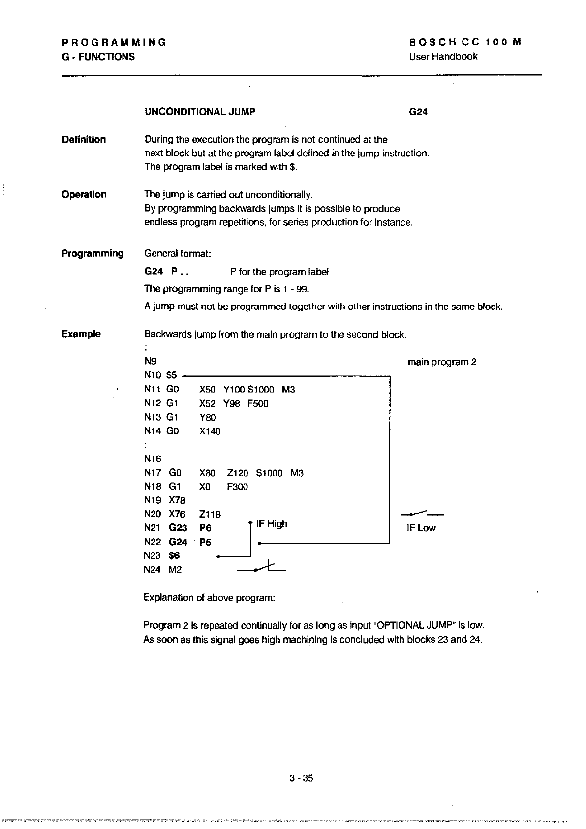
PROGRAMMING
G • FUNCTIONS
BOSCHCC100M
User Handbook
UNCONDITIONAL JUMP G24
Definition
Operation
Programming
Example
During the execution the program
next block but
The program label
The jump
By programming backwards jumps it
endless program repetitions. for series production for instance.
General format:
G24
P._
The programming range for P is 1 A
jump
must not be programmed together with other instructions in the same block.
Backwards jump from the main program
N9
N10 $5
N11
GO
N12
G1
N13
G1
N14
GO
atthe
program label defined in the
is
marked with $.
is
carried out unconditionally.
P for the program label
X5Q
Y100 $1000 M3
X52
Y98 F500
Y80
Xl40
is
not continued at the
jump
is
possible to produce
99.
to
the second block.
instruction.
main program 2
N16
GO
N17
N18
G1
N19
X78
N20
X76
N21
G23
N22 G24
N23
$6
N24 M2
Explanation of above program:
Program 2 is repeated continually for as
As
soon as this signal goes high machining
X80
Z120 51000 M3
XO
F300
Zl18
~IFHi9h
P6
PS
.
------L
--
IFLow
long as input "OPTIONAL JUMP" is low.
is
concluded with blocks 23 and
24.
3
-35
Page 95
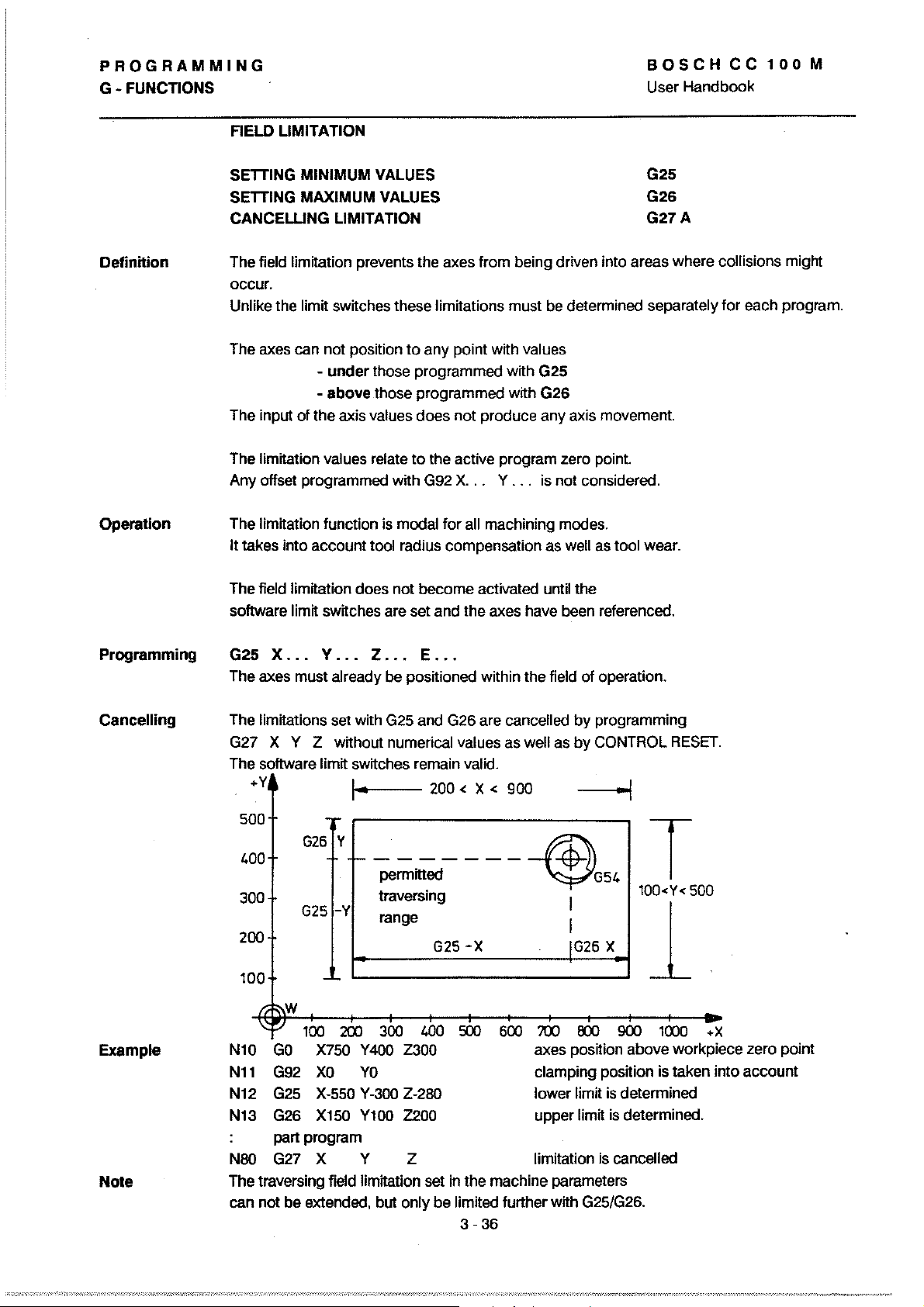
PROGRAMMING
G - FUNCTIONS
FIELD LIMITATION
BOSCH
User Handbook
CC
100
M
Definition
Operation
1001
G25
G26
G27A
wear.
SETTING MINIMUM VALUES
SETTING MAXIMUM VALUES
CANCEWNG
The field limttation prevents the axes from being driven into areas where collisions might
occur.
Unlike the limtt swttches these limitations must
The axes can not position
The input of the axis
limrtation values relate
The
Any offset programmed
limitation funclion
The
I1
takes into
field limrtation does not become activated until the
The
software
LIMITATION
be
determined separately for each program.
to
any point wtth values
- under those programmed wtth G25
- above those programmed
values does not produce any axis movement.
to
Ihe aclive program zero point.
with
G92
X.
is
modal for all machining modes.
accounllool
limit switches are set and Ihe axes have been referenced.
radius compensalion as weil as
..
wrth G26
Y...
is not considered.
Programming
Cancelling
Example
Note
x
...
Y
G25
The axes must
limrtations set with
The
G27 X Y
The software limit switches remain valid.
500
400
300
200
100
W
Nl0
GO
Nll
G92
G25
N12
N13
G26
part program
N80 G27 X Y
The traversing field limrtation set in the machine parameters
can not be extended, but
... Z ••• E •••
al
ready
be
posilioned within Ihe field of operation.
G25
and G26 are cancelled
Z without numerical values as weil as by CONTROL
'"'1-0----
G26
Y
________
G25
-Y
100
200
X750 Y 400
XO
X-550
X150
permitted
traversing I
range I
300
YO
Y-300
Yl00
200<
X<
900
~
G25
-x
500
400
Z300
Z-280
Z200
Z
only be limited further wrth G25/G26.
3
600
-36
by
programming
--I
~G54
IG26
X
700
OCXJ
900
axes position above workpiece zero poinl
clamping position is taken into account
lower limit
upper limrt
limitation
is
is
is cancelled
RESET.
T
100<Y<
500
1
1000
determined
determined.
+ X
Page 96

PROGRAMMING
G-FUNCnONS
BOSCH
User
Handbook
CC
100
M
Definition
SCAUNG
Modification
The contour
in the
the
programming
The scallng faetor always relates
(see next page);
FACTOR
cf
lines
specnied faetor area, without having
SWITCHING
the scaling
of
cf
the!wo
lactor
a workpiece are enlarged
the aetual
axes
contour
of
+Y
r-------,
I
I I
I I
I
I I
, I
L
______
..
J
01
the coordinate system.
or
reduced
to
change
lines.
to
a particular plane
a plane can
1 < Factor < 99.0
Faetor = 1
not
be modified separately.
1 > Factor > 0.00001
G36
Modification
range
of
scaling
faetor
Format
scaling faetor plane G 17
+X
...
0.00001
reduetion enlargement
)(.xxxxx
Scaling factor data is accepted in decimal format,
for instance:
XO.2
XS.O
(5
digits behind decimal point)
= 5-fold reduetion (corresponds
= 5-fold enlargement
to
99.0
reciprocal value
of
5)
3
-37
Page 97

PROGRAMMING
G - FUNCTIONS
BOSCHCC100M
User
Handbook
Display
Operation
The defined scaling faetors
displayed in main mode
- G36 always relates
Example: The programming cf the scaling
automatically influences X and
- G36 is modal and can
Cf,
Z,
E)
to
lactor
1.
A change in plane (G17/18/19) also resets a delined scaling lactor. This means
that the scaling factor needs
- G36 also operates in the E-axis,
alinear
-
Any variables called up in the program are subject
to
the variable
G36
-
axis, whatever working plane is selected.
the scaling laetor. The scaled values are, however,
lable
or
does
affect the contents
lor
the different axes can be
INFO
underthe
to
a particular plane.
Y in plane G17.
be
reset wtth CONTROL RESET, G36
to
be redelined after each plane selection.
ff
tool lable.
cf
the
ce 100M STATUS display.
lactor
this is delined as
zero shift lable if
lor
X
Xl
to
modification according
not
transferred into
it precedes G54-59 in the program.
G36
does
not
affect any preceding zero shifts.
Programing
Example
- II
G36 is programmed in several blocks they overwrite each other. The block
prgrammed has highest priority and the programmed scaling
last
remains effeetive until the next change in scaling lactor. The scaling
cf
the
scaling faetor is switched off
- G36 can be programmed together with main addresses
T,
H, but
6,
19,21,22
- G36 is
plane;
axes Z and E can be programmed independently in the same
block wtth a different scaling factor.
Nl
N2
N3
N4
N5
N6 M30
not
with any other G-codes
in one block.
to
be programmed with only one axis
lorworking
GO
G17
G36
GO
G36
plane G17 this is either X
YO
XO
X2
Y50
Xl
ZO
selection
scaling
traversing
swttch off scaling
by
programming the scaling laetor 1.
F,
S,
or
with M-codes
01
the working
orY;
01
X!Y
plane, clearing all programmed scaling faetors
lactor
lor
X and Y-axis, 2-lold magnification
to
Y100
mm
factor
by
means
3-38
Page 98

PROGRAMMING
G-FUNCnONS
BOSCH
Handbook
User
CC
100
M
Definition
Operation
Reference
Points
PROGRAMMABLE MIRRORING
or
2 specified axis(es) is (are) mirrored within the selected plane.
1
The
axes
are
programmed
The programmed workpiece positions are interpreted with
inverted sign in the
are mirrored around the active zero point. This is the
zero point which
the position stores with G92, presets
relevant axis. The position values
resulted after any possible setting
+Y
together
Y'
with
G3S.
or
zero shilts.
of
x
G38 switch
G39A
switch off
on
Programming
~;;;;;;;;;;;;;;;;;;;;~~----X'
x
y
~~--------------------------~~+X
M
M = machine zero point
= workpiece zero point
W
= clamping zero point (G92)
A
X'
= axis values after zero shilt
= axis values after zero shilt
Y'
x = X-axis values are mirrored
= Y -axIs values are mirrored
Y
Nl0
Nl1
G17
G3B
(G1B/G19)
XorYorZ
plane selection
(rnax. 3 axes)
to
N10 G39
N11
G39
XM(Z)
axis addresses are always programmed without axis values.
The
cancel all mirroring
selective cancelling
particular axes
3-39
of
mirroring in
Page 99

PROGRAMMING
G - FUNCTIONS
BOSCHCC100M
User
Handbook
Example
Original
Contour
G17
PROGRAMMABLE MIRRORING
+Y
360
2
30
200
3
100
1.6---------<i
100
Nl0
Nl1
N12
N13
N14
N15
N16
N17
N18
_ö--':':::LO--oS
200 300
(G17)
(G39)
G22
G38
G22
G38
G22
G38
G22
1.00
Pl
Y400
X
Pl
X500
XY
Pl
Y400
Y
Pl
E
6
!
5
500
+X
N21
N22
N23
N24
N25
N26
N27
N28
N29
G38/
G39
subprogram
$1
GO
Gl
X250
G3
Gl
X450
Y360
G99
execution in 1 st quadrant
no mirroring
program
execution in 2nd quadrant
X-va
lues
program
execution in 3rd quadrant
X and Y-values mirrored
program
execution in 4th quadrant (IV)
Y-values mirrored
"contour":
X500 Y300 Start
X450 F200
F500
Xl00
Y50
call-up
call-up
call-up
Y150 R-150
End (E)
(I)
mirrored
(111)
(11)
(S)
Operating
Sequence
during
Mirroring
Note
N19
N20 M30
..
t~
'I
I~
L / S
S3
G39
r.------~----
1
~s,
w
~
-
------
------
-;I
Cl
I.
-
When the values are mirrored
G41
into G42 and G3 into G2 etc. internally. See also examples
This is
See
not
the case when
example
111.
the
for
just
values
3 - 40
one axis the control converts
for
2 axes are mirrored.
mirroring cancelled in both axes
- tool path
for
mirroring
operations
eauxiliary points
11
and
IV.
Page 100
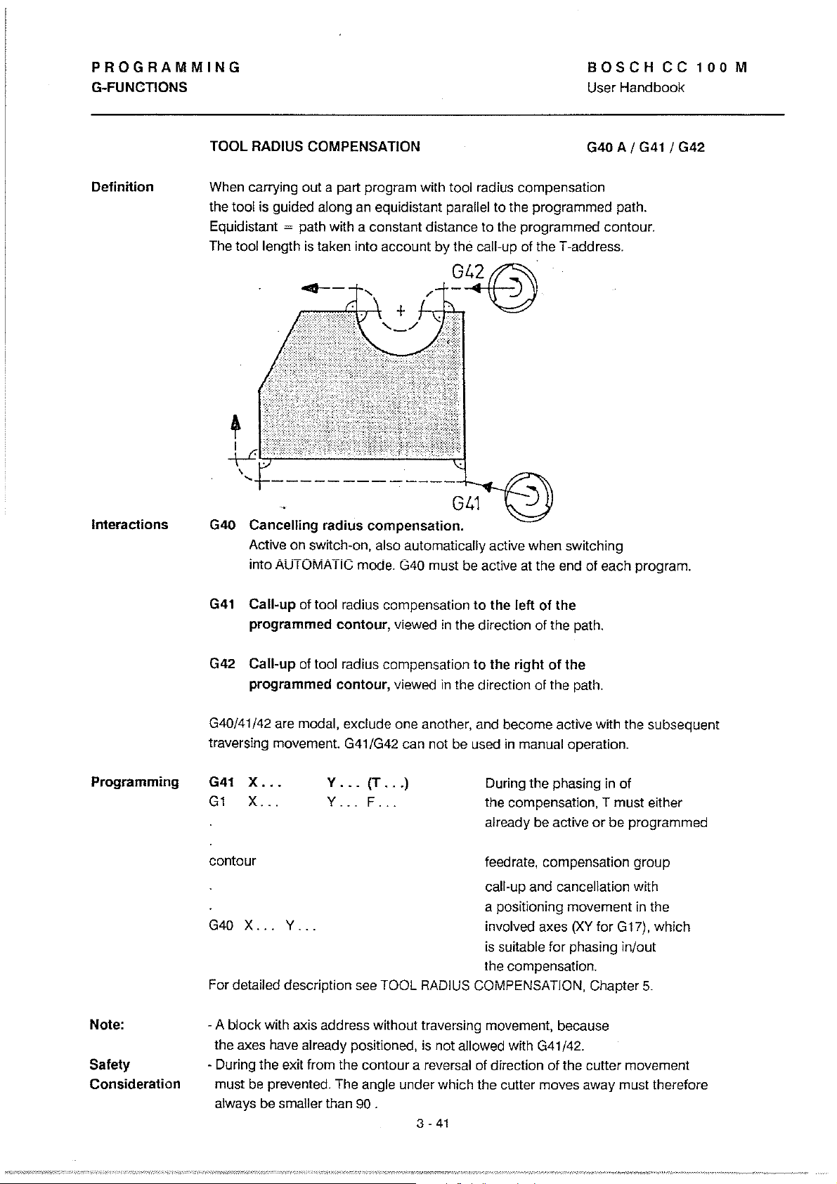
PROGRAMMING
G-FUNCTIONS
BOSCHCC100M
User Handbook
Delinition
Interactions
TOOL RADIUS COMPENSATION
apart
When carrying out
tool is guided along an equidistant parallel to the programmed path.
the
Equidistant
The
toollength
= path with a constant distance to the programmed contour.
is
taken into account
program with tool radius compensation
by
the call-up
01
the T-address .
G40
./-,.-I;.l...G~
+
---------------~
GL.1
G40 Cancelling radius
Active on switch-on, also automatically active when switching
AUTOMATie mode.
into
compensation.
G40
must be active at the end
01
A I
G41
I G42
each program.
Programming
G41
Call-up
programmed
Call-up
G42
programmed contour, viewed in the direction of the path.
G40/41
142
traversing movement.
G41
X,
G1
X
contour
G40 X ... V ...
For detailed description see TOOL
01
tool radius compensation
contour,
01
tool radius compensation
are modal, exclude one another, and become active with the subsequent
G41/G42 can not be used
•.
...
V
...
V
... F ..
(T
viewed
...
)
.
RADIUS
to
the left
in
the direction
to
the
right
in
During the phasing in of
the compensation, T must either
already be active
feedrate, compensation group
call-up and cancellation with
a positioning movement in the
involved axes
is
suitable far phasing
the compensation.
COMPENSATION, Chapter
01
the
01
the path.
01 the
manual operation.
or
be programmed
(XV
for G 17), wh ich
in/out
5.
Note:
Salety
Consideration
- A block with axis address without traversing movement, because
al
the axes have
- During the exit Irom the contour areversal
mus! be prevented. The angle und er which the cutter moves away must therelore
always be smaller than 90 .
ready positioned,
is
not allowed with G41/42.
01
direction
3 -
41
01
the cutter movement
 Loading...