

Bosch BRB-60HWD1N1-M19 Operation Manual
Bosch Inverter Ducted Packaged Heat Pump
19 SEER Series (5 Ton Capacity)
R410A
Installation & Operation Manual
BTC 761701105 A (2019/03) US

|
2
Bosch Inverter Ducted Packaged Heat Pump Installation & Operation Manual
03.2019 | BTC 761701105 AData subject to change

Installation & Operation Manual Bosch Inverter Ducted Packaged Heat Pump | 3
Table of Contents
1 Key to Symbols and Safety Instructions 4
1.1 Key to Symbols 4
1.2 Safety 4
2 Component Location 6
3 Dimensions 7
3.1 Unit Dimensions 7
3.2 Dimensions - Back and Bottom 8
3.3 Dimensions - Right and Top 9
4 Installation 10
4.1 Pre-Installation 10
4.2 Rigging And Lifting 10
4.3 Location Restrictions 10
4.4 Rooftop Installation - Curb Mounting 12
5 Airfl ow Performance 13
6 Indoor Fan Motor Function 14
13 System Operation and Troubleshooting 22
13.1 Control Logic Description 22
13.2 Sensors (Thermistors/Pressure Transducer) 22
13.3 Defrost Description 23
13.4 Compressor Crankcase Heater Description 23
13.5 Reversing Valve Operation 23
13.6 Protection Functions 24
13.7 Fault Code Table 25
13.8 Parameter Point Check Table 26
13.9 Control Board Overview 27
13.10 Error Code Troubleshooting 28
13.11 Temperature and Resistance Relationship Tables (for Sensors) 34
13.12
Temperature and Resistance Relationship Tables (for T5 & Tf Sensors)
13.13 Wiring Diagram 37
35
14 Maintenance 38
14.1 Cleaning Precautions 38
14.2 Regular Maintenance 38
7 Ductwork 14
8 Condensate Drain Connection 16
8.1 Install Drain Pipe 16
9 Air Filter (Not Factory-Installed) 16
10 Electrical Wiring 17
10.1 Power Wiring 17
10.2 Grounding 17
10.3 Control Wiring 17
11 Start Up 19
11.1 System Start Up 19
12 System Charge Adjustment 20
12.1 Charging: Weigh-In Method 20
12.2 S ubc ooli ng C harg ing and Refr iger ant Adju stm ent I n C ooli ng
(Above 55°F Outdoor Temp.) 20
BTC 761701105 A | 03.2019
Data subject to change
|
4
Bosch Inverter Ducted Packaged Heat Pump Installation & Operation Manual
1 Key to Symbols and Safety Instructions
1.1 Key to Symbols
Warnings
Warnings in this document are identifi ed by a
warning triangle printed against a grey background.
Keywords at the start of a warning indicate the type and
seriousness of the ensuing risk if measures to prevent the
risk are not taken.
The following keywords are defi ned and can be used in this document:
DANGER indicates a hazardous situation which, if not avoided,
will result in death or serious injury.
WARNING indicates a hazardous situation which, if not
avoided, could result in death or serious injury.
CAUTION indicates a hazardous situation which, if not avoided,
could result in minor to moderate injury.
NOTICE is used to address practices not related to personal
injury.
Important information
1.2 Safety
Please read before proceeding
DANGER: HIGH VOLTAGE
Failure to follow this warning could result in property
damage, severe personal injury, or death.
WAIT THREE (3) MINUTES after disconnecting power
prior to touching electrical components as they may
hold a dangerous charge of 380 VDC,then verify DC
Voltage is less than 42VDC at inverter TEST POINTS
P-N.
NOTICE:
This document is customer property and is to remain
with this unit. Please return to service information
pack upon completion of work.
These instructions do not cover all variations in
systems or provide for every possible contingency to
be met in connection with the installation.
Should further information be desired or should
particular problems arise which are not covered
sufficiently for the purchaser’s purposes, the matter
should be referred to your installing dealer or local
distributor.
This symbol indicates important information where
there is no risk to people or property.
This document contains a wiring diagram and service
information. This is customer property and is to remain with this
unit. Please return to service information pack upon completion
of work.
WARNING:
This information is intended for use by individuals
possessing adequate backgrounds of electrical
and mechanical experience. Any attempt to repair
a central air conditioning product may result in
personal injury and/or property damage.
WARNING: ELECTRICAL SHOCK
Failure to follow this warning could result in property
damage, severe personal injury, or death.
Disconnect all electric power, Including remote
disconnects before servicing. Follow proper lockout/
tagout procedures to ensure the power cannot be
inadvertently energized.
03.2019 | BTC 761701105 AData subject to change
Installation & Operation Manual Bosch Inverter Ducted Packaged Heat Pump | 5
WARNING: PERSONAL INJURY/ENVIRONMENTAL HAZARD
Any attempt to repair a central air conditioning
product may result in property damage, severe
personal injury, or death.
These units use R-410A refrigerant which operates
at 50 to 70% higher pressures than R-22. Use only
R-410A approved service equipment. Refrigerant
cylinders are painted a “Rose” color to indicate the
type of refrigerant and may contain a “dip” tube
to allow for charging of liquid refrigerant into the
system. All R-410A systems with variable speed
compressors use a POE oil (VG74 or equivalent )
that readily absorbs moisture from the atmosphere.
To limit this ‘hygroscopic“ action, the system should
remain sealed whenever possible. If a system has
been open to the atmosphere for more than 4 hours,
the compressor oil must be replaced. Never break a
vacuum with air and always change the driers when
opening the system for component replacement.
CAUTION: HOT SURFACE
Do not touch top of compressor. May cause minor to
severe burning. Failure to follow this Caution could
result in property damage or personal injury.
CAUTION: BURN HAZARD
Failure to follow this warning will result in abrupt
release of system charge and may result in personal
injury and/or property damage. Extreme caution
should be exercised when applying gauges to service
ports.
WARNING: ELECTRICAL SHOCK
Failure to follow this warning could result in property
damage, severe personal injury, or death.
Grounding is essential before connecting electrical
supply.
WARNING:
This product can expose you to chemicals including
Lead and Lead components, which are known to the
State of California to cause cancer and birth defects
or other reproductive harm. For more information
go to
www.P65Warnings.ca.gov.
CAUTION: HIGH PRESSURE
Failure to follow proper procedures can result in
personal illness or injury or severe equipment
damage.System contains oil and refrigerant under
high pressure. Recover refrigerant to relieve pressure
before opening system.
WARNING: GROUNDING REQUIRED
Failure to inspect or use proper service tools may
result in equipment damage or personal injury.
Reconnect all grounding devices. All parts of this
product that are capable of conducting electrical
current are grounded. If grounding wires, screws,
straps, clips, nuts, or washers used to complete a
path to ground are removed for service, they must
be returned to their original position and properly
fastened.
BTC 761701105 A | 03.2019
Data subject to change
|
6
Bosch Inverter Ducted Packaged Heat Pump Installation & Operation Manual
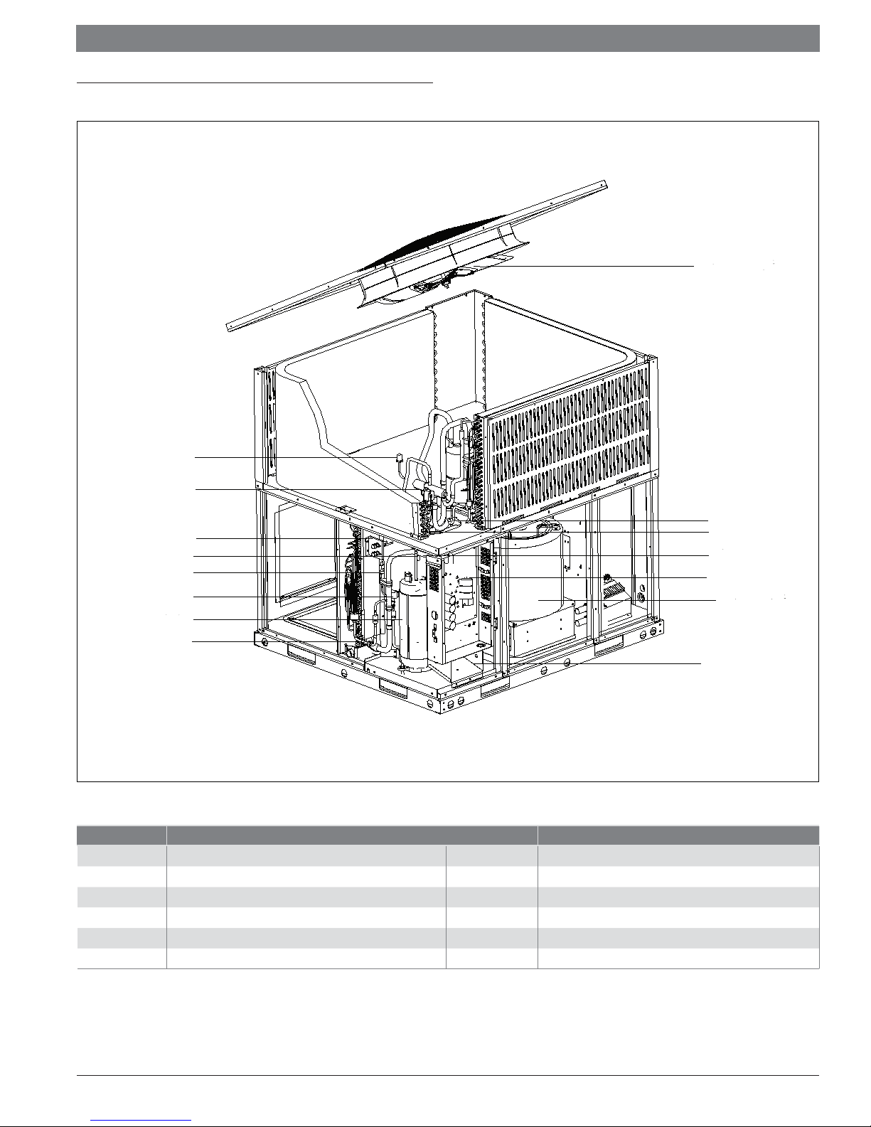
2 Component Location
Outdoor Fan
HPS
RV
Service Valves
T5
PT
EEV
COMP
T2
Figure 1
Component Descriptions Component Descriptions
HPS High pressure switch
PT Pressure transducer Tf Radiator temp. sensor
T2 Indoor coil temp. sensor Th Comp. return temp. sensor
T3 Condenser temp. sensor EEV Electronic expansion valve
T4 Ambient temp. sensor RV Reversing valve
T5 Comp. discharge temp. sensor COMP Compressor
Table 1 Component Descriptions
T3L Condensor outlet temp. sensor
T3L
T3
Th
Tf
Indoor Fan
T4
03.2019 | BTC 761701105 AData subject to change
Installation & Operation Manual Bosch Inverter Ducted Packaged Heat Pump | 7
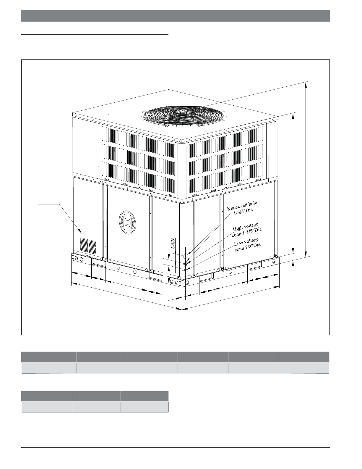
3 Dimensions
3.1 Unit Dimensions
H
A
Front
.
.
.
2-3/16"
9-5
/16"
6-
5/8"
B
L
Figure 2
6-5/8"
5-1/2"
2-1/
"
15-1/2
/8"
-5
6
"
4
W
Heat Pump Model L W H A B
6
-5/8"
8-1/16"
2-3/8"
BRB-60HWD1N1-M19 51-9/16" 44-13/16" 51-7/16" 47-5/16" 19-11/16"
Table 2 Unit Dimensions
Heat Pump Model Net Weight Gross Weight
BRB-60HWD1N1-M19 561 lbs (255kg) 596 lbs (271kg)
Table 3 Unit Weights
BTC 761701105 A | 03.2019
Data subject to change
|
8
Bosch Inverter Ducted Packaged Heat Pump Installation & Operation Manual
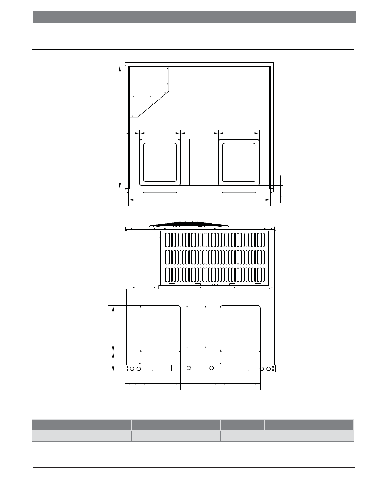
3.2 Dimensions - Back and Bottom
Bottom view
D
4-3/4"
OPTIONAL
RETURN
AIR
Back view
E
OPENING
F
12-15/16"
C
E
OPTIONAL
SUPPLY
OPENING
AIR
2-3/16"
G
6-3/16"
5-3/16"
Figure 3
Heat Pump Model C D E F G H
BRB-60HWD1N1-M19 49-1/4" 42-1/2" 14-1/8" 16-1/8" 15-7/8" 13-7/8"
Table 4 Dimensions - Back and Bottom
SUPPLY
DUCT
OPENING
H
13-9/16"
RETURN
DUCT
OPENING
H
03.2019 | BTC 761701105 AData subject to change
Installation & Operation Manual Bosch Inverter Ducted Packaged Heat Pump | 9
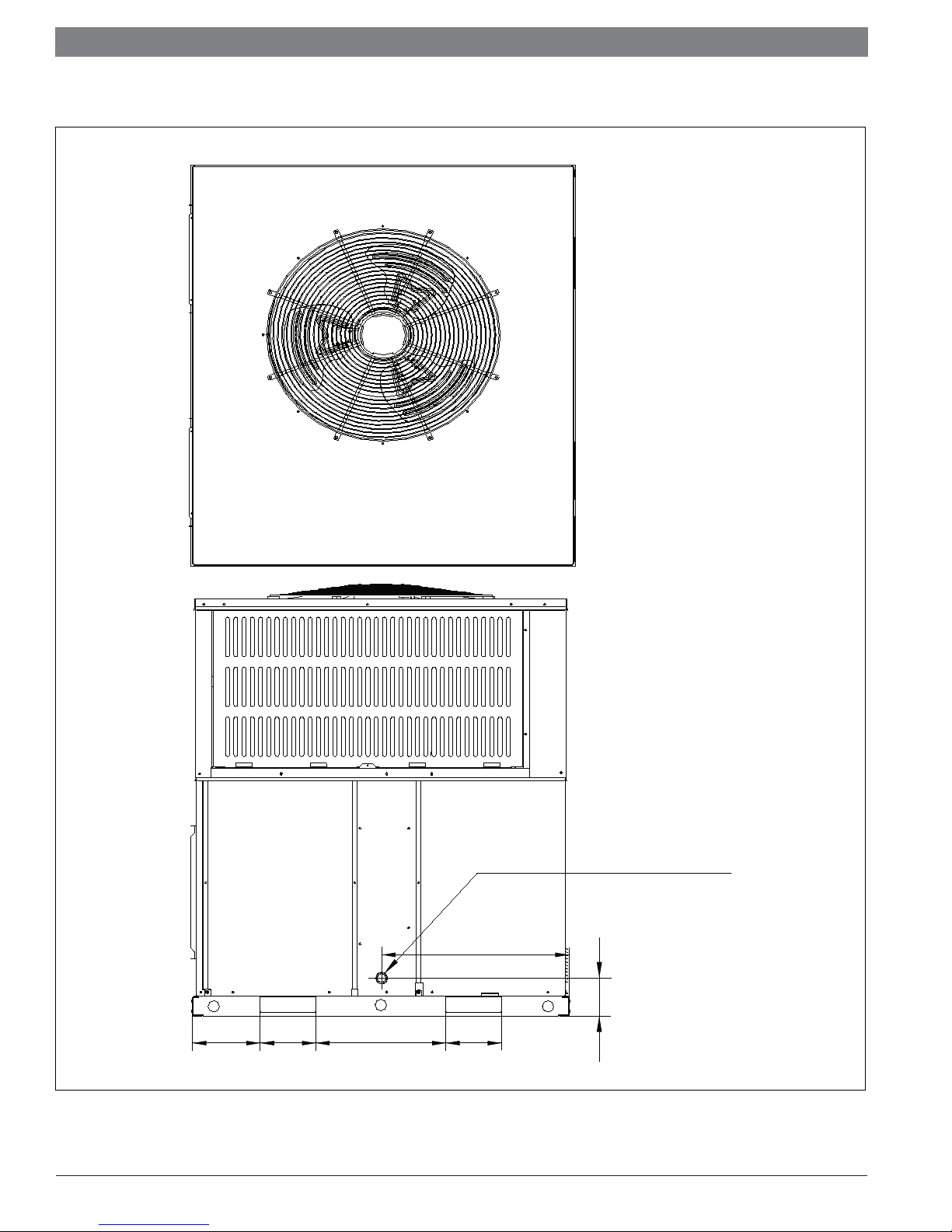
3.3 Dimensions - Right and Top
Top View
Right side view
8-1/16"
Figure 4
BTC 761701105 A | 03.2019
6-5/8"
15-1/2"
Condensate drain connection
3/4" NPT (Trap required)
22-3/8"
4-9/16"
6-5/8"
Data subject to change
|
10
Bosch Inverter Ducted Packaged Heat Pump Installation & Operation Manual
4 Installation
4.1 Pre-Installation
Before installation, carefully check the following:
1. Unit should be installed in accordance with national and local
safety codes, including but not limited to ANSI/NFPS No. 70, local
plumbing and wastewater codes and any other applicable codes.
2. For rooftop installation, be sure the structure has enough strength
to support the weight of unit. Unit must be installed on a fi eld
supplied roof curb or rack and leveled.
3. For ground level installation, a fi eld supplied level slab must be
used.
4. Condenser airfl ow should not be restricted.
5. On applications when a roof curb is used, the unit must be
positioned on the curb so the front of the unit is tight against
the curb. If the unit is to be mounted on a curb in a downfl ow
application, refer to Figure 13, and convert panels prior to rigging
and lifting. The panel removal process may require the unit to be on
the ground.
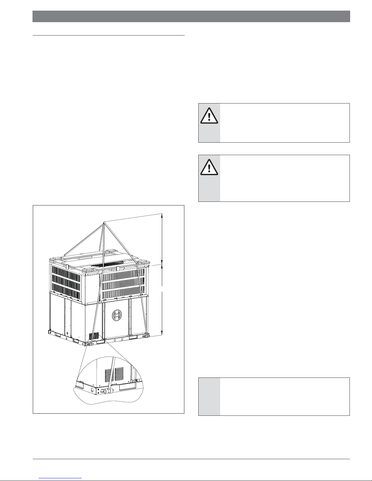
4.2 Rigging And Lifting
Exercise care when moving the unit. Do not remove any packaging until
the unit is near the place of installation. Rig the unit by attaching chain or
cable slings to the lifting holes provided in the base rails. Spreader bars,
whose length exceeds the largest dimension across the unit, MUST be
used across the top of the unit.
When rigging/lifting the unit, the minimum height between the top of the
rigging cables' connection point and top of unit should be 36 in. Refer to
Figure 5.
CAUTION:
Before lifting, make sure the unit weight is
distributed equally on the rigging cables so it will lift
evenly.
CAUTION:
All panels must be secured in place when the unit is
lifted. The condenser coils should be protected from
rigging cable damage with plywood or other suitable
material.
Figure 5
Minimum Height 36"
Unit Height
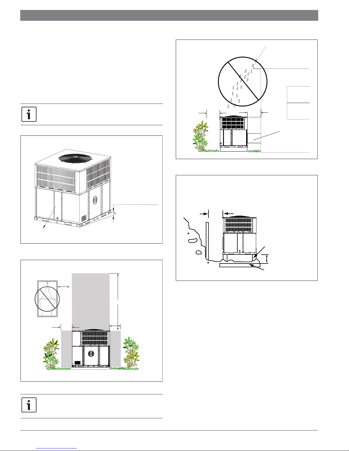
4.3 Location Restrictions
Ensure the top discharge area is unrestricted for at least 60 inches above
the unit.
Do not locate outdoor unit near bedrooms since normal operational noise
levels may be disturbing to building occupants.
Position unit to allow adequate space for unobstructed airfl ow, wiring, and
serviceability.
Do not restrict outdoor airfl ow. An air restriction at either the outdoor air
inlet or the fan discharge may be detrimental to compressor life.
Do not place the unit where water, ice, or snow from an overhang or roof
will damage or fl ood the unit. Do not install the unit on carpeting or other
combustible materials. Slab-mounted units should be at least 2 in. (51
mm) above the highest expected water and runoff levels. Do not use unit if
it has been under water.
Maintain a distance of 24 inches between units. Position unit so water,
snow, or ice from roof or overhang cannot fall directly on unit.
See Fig. 7 and Fig. 8 for minimum clearance requirements.
Cold climate considerations (heat pump only)
NOTICE:
Precautions must be taken for units being installed
in areas where snow accumulation and prolonged
below-freezing temperatures occur.
03.2019 | BTC 761701105 AData subject to change
Installation & Operation Manual Bosch Inverter Ducted Packaged Heat Pump | 11
Units should be elevated 3-12 inches above the pad or rooftop,
depending on local weather. This additional height will allow
drainage of snow and will permit condensate water to drain
when the unit is in defrost mode. Ensure that drain holes in
unit base pan are unobstructed, preventing drainage of defrost
water (See Fig.9).
If possible, avoid locations that are prone to snow drifts. If not
possible, a snow drift barrier should be installed around the
unit to prevent a build-up of snow on the sides of the unit.
Ensure that Condensate Drain side is pitched lower than the
opposite side.
Min. 24"
Access Panel
Figure 8
Min. 12" to
Shrubbery
Supply Air Duct
0˘ h≤ 25mm(
Condensate drain side
1°)
Figure 6
Avoid Install
Near Bedrooms
Min. 60" Unrestricted
Min. 24"
Access Panel
Min. 24"
Access Panel
Figure 7
A minimum clearance of 24" should be maintained adjacent to
all access/service panels. Refer to local code requirements for
additional clearance requirements.
Min 24"
Snow
barrier
Snow legs
pad
3- 12" Elevation
Figure 9
Corrosive Environment
Exposure to a corrosive environment may shorten the life of the
equipment, corrode metal parts, and/or negatively aff ect unit
performance. Corrosive elements include, but are not limited to: sodium
chloride, sodium hydroxide, sodium sulfate, and other compounds
commonly found in ocean water, sulfur, chlorine, fl uorine, fertilizers, and
various chemical contaminants from industry/manufacturing plants. If
installed in areas which may exposed to corrosive environments, special
attention should be given to the equipment placement and maintenance.
Lawn sprinklers/hoses/waste water should not spray directly
on the unit cabinet for prolonged periods of time.
In coastal areas: locate the unit on the side of the building or
roof away from the waterfront.
Fencing or shrubbery may provide some shielding protection
to the unit, however minimum unit clearances must still be
maintained.
Every three months, wash the outdoor coil and any exposed
cabinet surfaces.
BTC 761701105 A | 03.2019
Data subject to change
|
12
Bosch Inverter Ducted Packaged Heat Pump Installation & Operation Manual
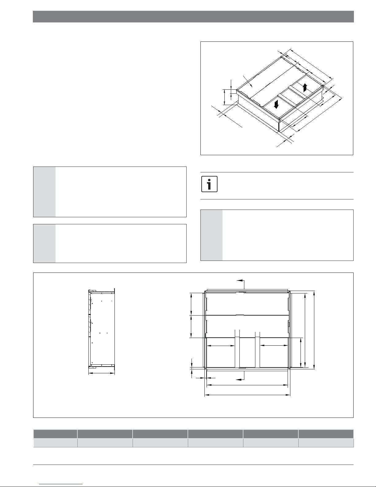
4.4 Rooftop Installation - Curb Mounting
The manufacturer does not supply roof curbs, they must be fi eld supplied.
On applications when a roof curb is used,the unit must be positioned on
the curb so the front of the unit is tight against the curb (see Figure 10
Roof Curb Dimension).
The default orientation from the factory is for horizontal airfl ow. Convert
the unit to downfl ow using the following procedure:
1. Remove the sheet metal screws securing the supply air cover and
the sheet metal screws securing the return air cover from the base
of the unit. Remove the covers from the base. See Figure 13.
2. Place the covers over the horizontal supply and return openings
(painted side out). Align the screw holes, and secure using the
same screws removed in step 1. See Figure 13.
Install the fi eld-supplied roof mounting curb according to the Installation
Instructions supplied with the curb. Install insulation, cant strips, roofi ng,
and fl ashing. Ductwork must be attached to curb.
Figure 11
Insulation layer
4-1/16"
14-1/4"
1-15/16"
Roof Curb Dimensions
1"
1-15/16"
1
2
-1/16"
4
1
2
-1/16"
1/4"
-
5
1
2-3/16"
16"
46-1/
1"
15-1/4"
"
16
NOTICE:
The gasketing of the unit to the roof curb is critical
for a water tight seal. Install gasketing material
supplied with the field supplied roof curb.
Improperly applied gasketing also can result in air
leaks and poor unit performance.
NOTICE:
The unit must be secured to the curb by installing
screws through the bottom of the curb flange and
into the unit base rails.
A-A
B
NOTES:
1. Roof curb must be set up for unit being installed.
2. Seal strip must be applied, as required, to unit being installed.
4. Attach ductwork to curb (flanges of duct rest on curb).
5. Recommended insulated panels: 1 in. (25.4 mm) thick fiberglass 1 lb. density.
For units applied with a roof curb, the minimum clearance
may be reduced from 1 inch to 1/2 inch between combustible
roof curb material and supply air duct.
NOTICE: UNIT/STRUCTURAL DAMAGE HAZARD
Failure to follow this caution may result in property
damage. Ensure there is sufficient clearance for
saw blade when cutting the outer horizontal flange
of the roof curb so there is no damage to the roof or
flashing.
A
F
12-1/16" 12-1/16"
C
C
39-1/2"
E
SUPPLY
1"
AIR
1"
A
43-9/16"
RETURN
AIR
D
Figure 10
Roof Curb Details
BCDEF
CURB 14-1/4" 15-1/4" 46-1/16" 16" 42-3/16"
Table 5 Roof Curb Details -
inches
03.2019 | BTC 761701105 AData subject to change
 Loading...