


Bosch BOVA, BOVA-36, BOVA-60 Installation Instructions Manual
Bosch BOVA Split System Heat Pump
Condensing Units Up to 18 SEER
2-3-4-5 Ton Capacity
R410A
Installation Instructions

|
2
Bosch IDS BOVA Installation Instructions
12.2016 | Bosch Thermotechnology Corp.Data subject to change

Installation Instructions Bosch IDS BOVA | 3
Table of Contents
1 Key to symbols and safety instructions 4
2 Unit location considerations 6
3 Unit preparation 8
4 Setting the unit 8
5 Refrigerant line considerations 9
6 Refrigerant line routing 10
7 Refrigerant line brazing 11
8 Refrigerant line leak check 13
9 Evacuation 13
10 Service valves 14
11 Electrical - low voltage 15
12 Electrical - high voltage 16
13 Start up 17
14 System charge adjustment 18
15 System operation and troubleshooting 21
Bosch Thermotechnology Corp. | 12.2016
Data subject to change
|
4
Bosch IDS BOVA Installation Instructions
1 Key to symbols and safety instructions
1.1 Key to symbols
Warnings
Warnings in this document are identifi ed by a
warning triangle printed against a grey background.
Keywords at the start of a warning indicate the type and seriousness
of the ensuing risk if measures to prevent the risk are not taken.
The following keywords are defi ned and can be used in this document:
DANGER indicates a hazardous situation which, if not avoided, will result
in death or serious injury.
WARNING indicates a hazardous situation which, if not avoided, could
result in death or serious injury.
CAUTION indicates a hazardous situation which, if not avoided, could
result in minor to moderate injury.
NOTICE is used to address practices not related to personal injury.
1.2 Safety
Please read before proceeding
CAUTION:
This document is customer property and is to remain with
this unit. Please return to service information pack upon
completion of work.
These instructions do not cover all variations in systems
or provide for every possible contingency to be met in
connection with the installation.
Should further information be desired or should particular
problems arise which are not covered sufficiently for the
purchaser’s purposes, the matter should be referred to your
installing dealer or local distributor.
The manufacturer recommends installing only approved
matched indoor and outdoor systems. All of the manufacturer’s split
systems are A.H.R.I. rated only with TXV indoor systems. Some of the
benefi ts of installing approved matched indoor and outdoor split systems
are maximum effi ciency, optimum performance and the best overall
system reliability.
Important information
This symbol indicates important information where
there is no risk to people or property.
This document contains a wiring diagram and service information.
This is customer property and is to remain with this unit. Please return to
service information pack upon completion of work.
CAUTION:
This information is intended for use by individuals possessing
adequate backgrounds of electrical and mechanical
experience. Any attempt to repair a central air conditioning
product may result in personal injury and/or property
damage.
WARNING: HAZARDOUS VOLTAGE
Failure to follow this warning could result in property damage,
severe personal injury, or death.
Disconnect all electric power, Including remote disconnects
before servicing. Follow proper lockout/tagout procedures to
ensure the power cannot be inadvertently energized.
12.2016 | Bosch Thermotechnology Corp.Data subject to change
Installation Instructions Bosch IDS BOVA | 5
WARNING: REFRIGERANT OIL
Any attempt to repair a central air conditioning product may
result in property damage, severe personal injury, or death.
These units use R-410A refrigerant which operates at 50 to
70% higher pressures than R-22. Use only R-410A approved
service equipment. Refrigerant cylin-ders are painted a
“Rose” color to indicate the type of refrigerant and may
contain a “dip” tube to allow for charging of liquid refrigerant
into the system. All R-410A systems with variable speed
compressors use a PVE oil that readily absorbs moisture
from the atmosphere To limit this ‘hygroscopic“ action. the
system should remain sealed whenever possible. If a system
has been open to the atmosphere for more than 4 hours, the
compressor oil must be replaced. Never break a vacuum with
air and always change the driers when opening the system for
component replacement.
CAUTION: HOT SURFACE
May cause minor to severe burning. Failure to follow this
Caution could result in property damage or personal injury.
Do not touch top of compressor.
WARNING: SERVICE VALVES
Failure to follow this warning will result in abrupt release
of system charge and may result in personal injury and/
or property damage. Extreme caution should be exercised
when opening the Liquid Line Service valve. Turn valve stem
counterclockwise only until the stem contacts the rolled edge.
No torque is required.
WARNING: BRAZING REQUIRED
Failure to inspect lines or use proper service tools may result
in equipment damage or personal injury. if using existing
refrigerant lines make certain that all joints are brazed, not
soldered.
WARNING: HIGH CURRENT LEAKAGE
Failure to follow this warning could result in property damage,
severe personal injury, or death.
Grounding is essential before connecting electrical supply.
CAUTION: CONTAINS REFRIGERANT
Failure to follow proper procedures can result in personal
illness or injury or severe equipment damage.System
contains oil and refrigerant under high pressure. Recover
refrigerant to relieve pressure before opening system.
CAUTION: GROUNDING REQUIRED
Failure to inspect or use proper service tools may result
in equipment damage or personal injury. Reconnect all
grounding devices. All parts of this product that are capable
of conducting electrical current are grounded. if grounding
wires, screws, straps, clips, nuts, or washers used to
complete a path to ground are removed for service, they must
be returned to their original position and properly fastened.
CAUTION: INDOOR UNIT REQUIRED
The indoor units must be matched with TXV. The model of TXV
can be changed according to the system capacity.
Bosch Thermotechnology Corp. | 12.2016
Data subject to change
|
6
Bosch IDS BOVA Installation Instructions
2 Unit location considerations
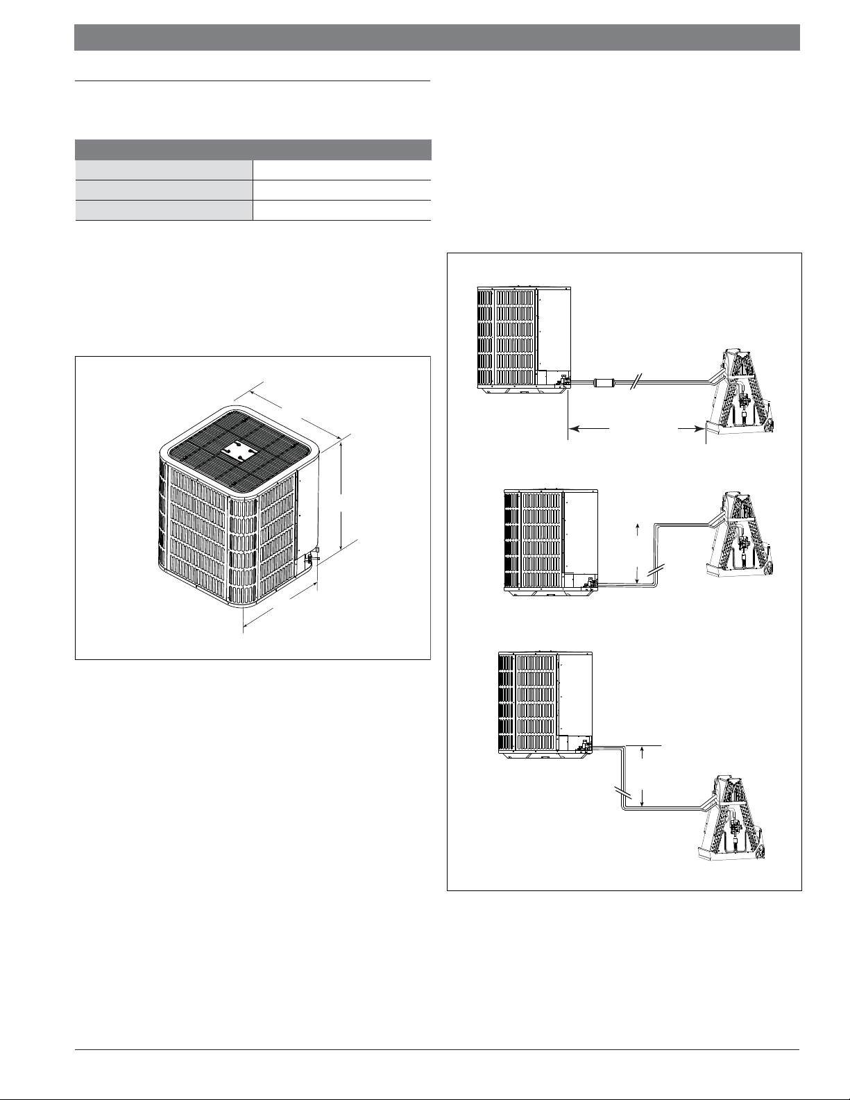
2.1 Unit dimensions
Unit Dimensions
Models H x W x L (Inches)
BOVA-36 24-15/16 x 29-1/8 x 29-1/8
BOVA-60 33-3/16 x 29-1/8 x 29-1/8
Table 1
The unit’s weight values is on the carton box.
When mounting the outdoor unit on a roof, be sure the roof will support the unit’s
weight. Properly selected isolation is recommended to prevent sound or vibration
transmission to the building structure.
W
2.2 Refrigerant piping limits
Maximum line equivalent length = 100 feet.
Maximum vertical equivalent length = 50 feet.
Use only the line diameters indicated in Table 5.1.
If the suction line sets are greater than 60 feet do not use a larger suction
line than recommended.
Standard Line
Set 100’ Max
Line Length
Figure 1
H
x
a
M
0
’
5
e
t
L
i
f
L
i
n
L
50’ Max
Line Lift
Figure 2
12.2016 | Bosch Thermotechnology Corp.Data subject to change
Installation Instructions Bosch IDS BOVA | 7
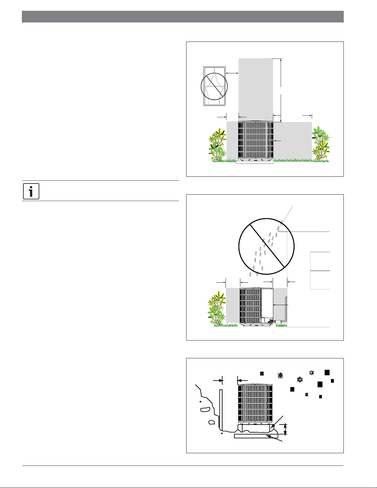
2.3 Location restrictions
Ensure the top discharge area is unrestricted for at least 60 inches above the unit.
Do not locate outdoor unit near bedrooms since normal operational sounds may be
objectionable.
Avoid Install
Near Bedrooms
Position unit to allow adequate space for unobstructed airfl ow, wiring, refrigerant
lines, and serviceability.
Allow a minimum of 12 in. clearance on one side of access panel to a wall and a
minimum of 24 in. on the adjacent side of access panel.
Maintain a distance of 24 in. between units.
Position unit so water, snow, or ice from roof or overhang cannot fall directly on unit.
See Fig. 3 and Fig. 4.
Cold climate considerations (heat pump only)
Precautions must be taken for units being installed in areas where
snow accumulation and prolonged below-freezing temperatures occur.
Units should be elevated 3-12 inches above the pad or rooftop, depending
on local weather. This addi-tional height will allow drainage of snow and ice
melted durIng defrost cycle prior to its refreezlng. Ensure that drain holes
in unit base pan are not obstructed, preventing drainage of defrost water
(Fig. 5).
If possible, avoid locations that are likely to accu-mulate snow drifts. if not
possible, a snow drift barrier should be installed around the unit to prevent
a build-up of snow on the sides of the unit.
Figure 3
Min. 20” to
Shrubbery
Min. 20” to
Shrubbery
Min. 60” Unrestricted
Min. 36”
Unrestricted
Access Panel
Min. 36” to
Shrubber
Bosch Thermotechnology Corp. | 12.2016
Access Panel
Figure 4
Min 12"
Snow
barrier
Snow legs
3- 12" Elevation
pad
Figure 5
Data subject to change
|
8
Bosch IDS BOVA Installation Instructions
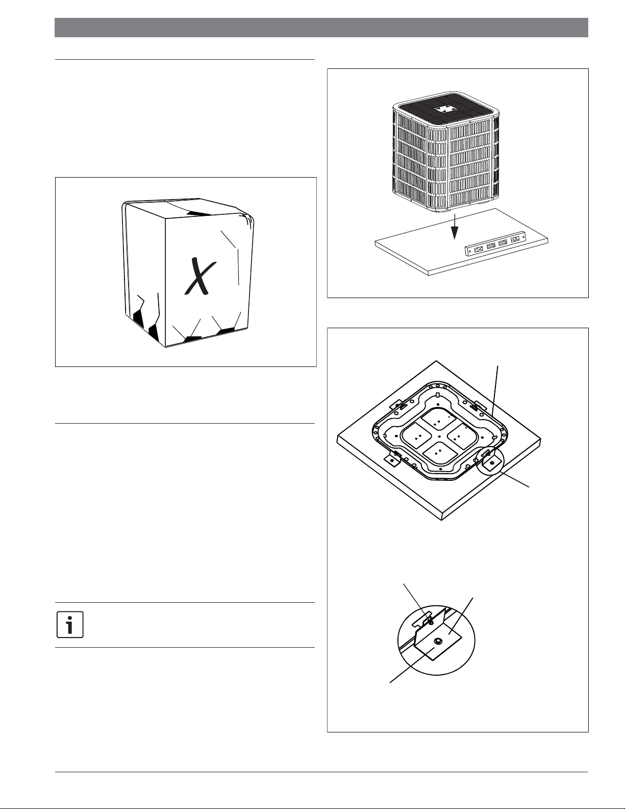
3 Unit preparation
3.1 Prepare the unit for installation
STEP 1 - Check for damage and report promptly to the carrier any damage
found to the unit (Fig. 6).
The charge port can be used to check to be sure the refrigerant charge has
been retained during shipment.
Figure 7
Figure 6
4 Setting the unit
4.1 Pad installation
When installing the unit on a support pad, such as a concrete slab, consider the
following:
The pad must be at least 1-2” larger than the unit on all sides.
The pad must be separate from any structure.
The pad must be level.
The pad must be high enough above grade to allow for drainage.
The pad location must comply with National, State, and Local codes.
These instructions are intended to provide a method to tie-down system to
cement slab as a securing procedure for high wind areas. Check Local
Codes for tie-down methods and protocols.
#7 X 3/8” Self Tapping Screws
(Don’t Exceed 3/8” long)
Detail A
The dimension
see Unit Dimensions.
See Detail A
Brackets:
2" width, 1/16" thickness,
height as required.
Available from distributor
or in market place.
1/4” Χ 1-1/2” Hex Washer Head Concrete Screws
(3/16” Pilot Hole Needed. Pilot Hole Should Be1/4” Deeper
Than The Fastener Embedment)
Figure 8
12.2016 | Bosch Thermotechnology Corp.Data subject to change
Installation Instructions Bosch IDS BOVA | 9
5 Refrigerant line considerations
5.1 Refrigerant line and service valve connection sizes
Models Suction line Liquid line
BOVA-36 3/4 3/8 3/4 3/8
BOVA-60 7/8 3/8 7/8 3/8
Table 2
Suction line
connection
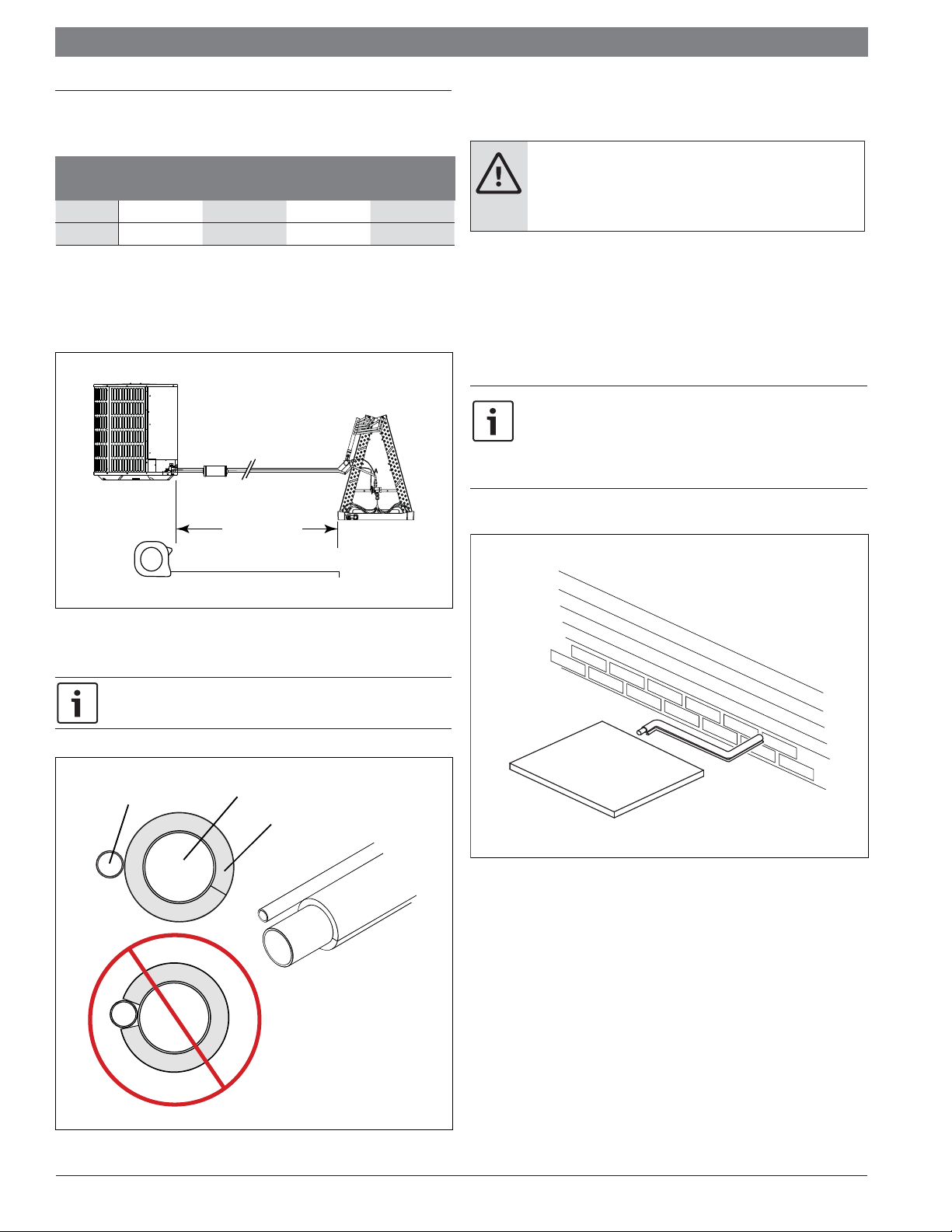
5.2 Required refrigerant line length
Determine required line length (Fig. 9).
Line Length
Liquid line
connection
5.4 Reuse existing refrigerant lines
CAUTION:
If using existing refrigerant lines make certain that all joints
are brazed, not soldered.
For retrofi t applications, where the existing refrigerant lines will be used, the
following precautions should be taken:
Ensure that the refrigerant lines are the correct size. Refer to Section 5.1
listed and Table 2.
Ensure that the refrigerant lines are free of leaks, acid, and oil.
The manufacturer recommends installing only approved matched indoor
and outdoor systems. All of the manufacturer’s split systems are A.H.R.I.
rated only with TXV indoor systems. Some of the benefi ts of installing
approved matched indoor and outdoor split systems are maximum
effi ciency, optimum per-formance and the best overall system reliability.
Figure 9
5.3 Refrigerant line insulation
The Suction Line must always be insulated. DO NOT allow the Liquid Line
and Suction Line to come in direct (metal to metal) contact.
Liquid Line
Suction Line
Insulation
Figure 11
Figure 10
Bosch Thermotechnology Corp. | 12.2016
Data subject to change
|
10
Bosch IDS BOVA Installation Instructions
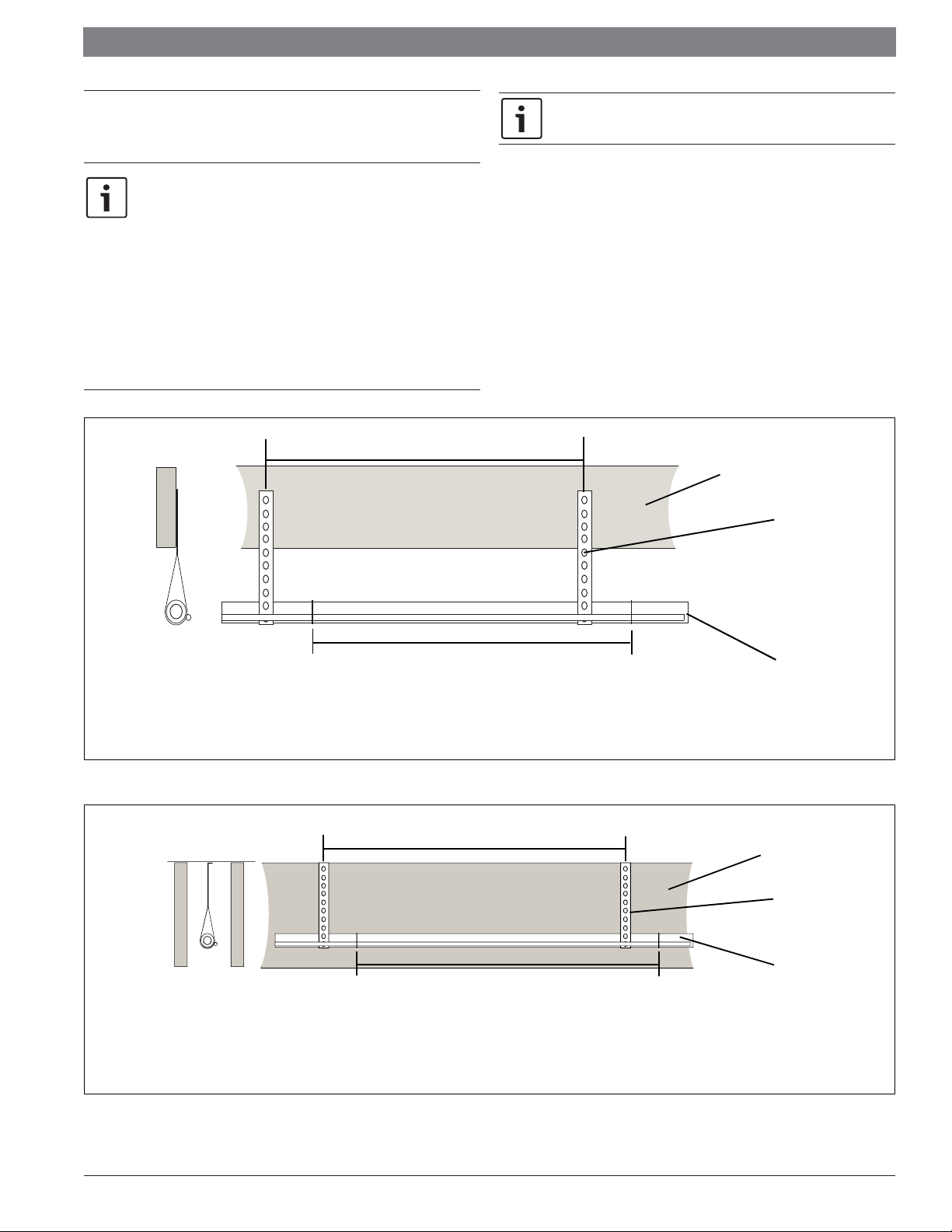
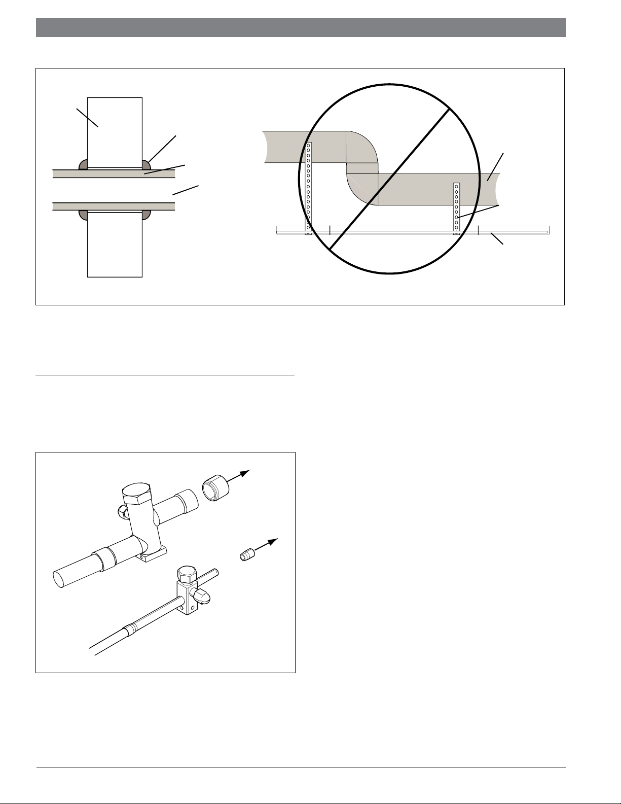
6 Refrigerant line routing
6.1 Precautions
Take precautions to prevent noise within the building structure due to
vibration transmission from the refrigerant lines. For Example:
When the refrigerant lines have to be fastened to floor joists or
other framing in a structure, use isolation type hangers.
Isolation hangers should also be used when refrigerant lines are
run in stud spaces or enclosed ceilings.
Where the refrigerant lines run through a wall or sill, they should
be insulated and isolated.
Isolate the lines from all ductwork.
Minimize the number of 90º turns.
8FeetMaximum
Comply with National, State, and Local Codes when isolating line sets from
joists, rafters, walls, or other structural elements.
Joist/Raft er
Isolator
Figure 12
Side View
Side View
8 Feet Maximum
Secure Suc tion line f rom joist s using isolators every 8 ft. Secure
Liquid Line directly to Suction line using tape,wire, or other
approp riate m ethod every 8 ft.
Isolation From Joist/Rafter
8 Feet Maximum
8FeetMaximum
Secure Suction Line using isolators every 8 ft. Secure Liquid Line
directly to Suction Line using tape, wir e, or other approp riate
method every 8 ft.
Isolation In Wall Spaces
Line Set
Wall
Isolator
Line Set
Figure 13
12.2016 | Bosch Thermotechnology Corp.Data subject to change
Installation Instructions Bosch IDS BOVA | 11
Wall
Sealant
Ductwork
Insulati on
Suction Line
Isolator
Line Set
Isolation Through Wall
Figure 14
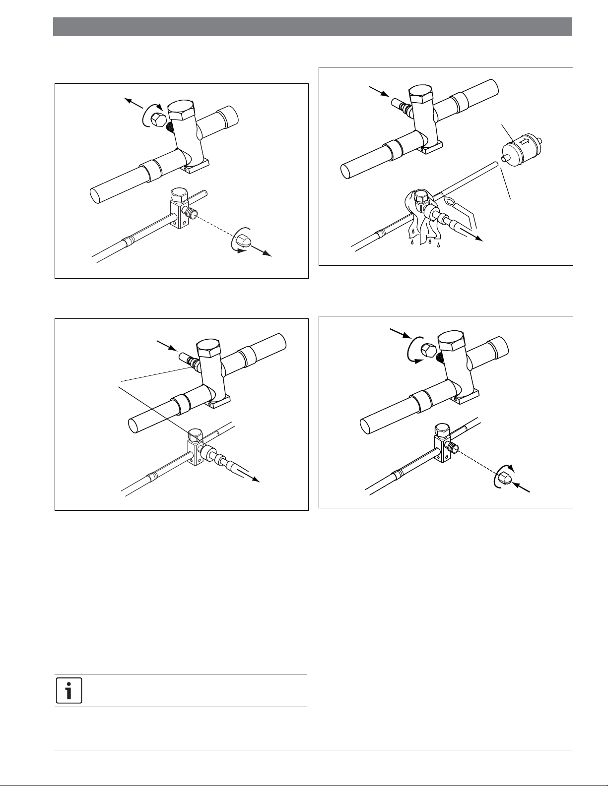
7 Refrigerant line brazing
7.1 Braze the refrigerant lines
1. Remove caps or plugs. Use a deburing tool to debur the pipe ends. Clean both
internal and external surfaces of the tubing using an emery cloth.
DO NOT hang line sets from duc two rk
Figure 15
Bosch Thermotechnology Corp. | 12.2016
Data subject to change
|
12
Bosch IDS BOVA Installation Instructions
2. Remove the pressure tap cap from both service valves.
Field supplied
and installed
3-4" from valve
Figure 18
Figure 16
3. Purge the refrigerant lines and indoor coil with dry nitrogen.
5. Replace the pressure tap caps after the service valves have cooled.
This pipe
must have
a thimble
Figure 17
4. Wrap a wet rag around the valve body to avoid heat damage and continue the
dry nitrogen purge (Fig. 18).
Braze the refrigerant lines to the service valves.
Check liquid line fi lter drier’s directional fl ow arrow to confi rm correct direction
of refrigeration fl ow (away from outdoor unit and toward evaporator coil) as
illustrated. Braze the fi lter drier to the Liquid Line.
Continue the dry nitrogen purge. Do not remove the wet rag until all brazing is
completed.
Figure 19
Remove the wet rag before stopping the dry nitrogen purge.
12.2016 | Bosch Thermotechnology Corp.Data subject to change
Installation Instructions Bosch IDS BOVA | 13
150 PSI
G
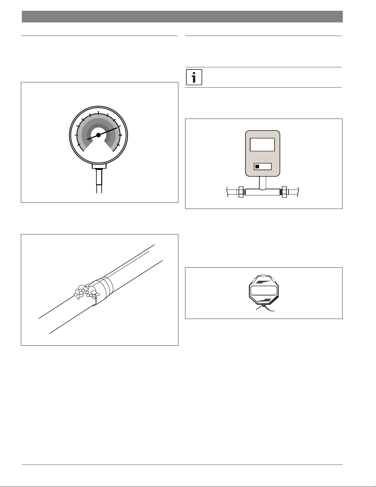
8 Refrigerant line leak check
8.1 Check for leaks
1. Pressurize the refrigerant lines and evaporator coil to 150 PSIG using dry
nitrogen.
Figure 20
2. Check for leaks by using a soapy solution or bubbles at each brazed location.
9 Evacuation
9.1 Evacuate the refrigerant lines and indoor coil
Do not open the service valves until the refrigerant lines and indoor coil
leak check and evacuation are complete.
1. Evacuate until the micron gauge reads no higher than 350 microns, then close
the valve to the vacuum pump.
0350
Microns
ON
OFF
Figure 22
2. Observe the micron gauge. Evacuation is complete if the micron gauge does not
rise above 500 microns in one (1) minute.
Figure 21
Once evacuation is complete blank off the vacuum pump and micron gauge,
and close the valves on the manifold gauge set.
1MIN.
Figure 23
Bosch Thermotechnology Corp. | 12.2016
Data subject to change
|
14
Bosch IDS BOVA Installation Instructions
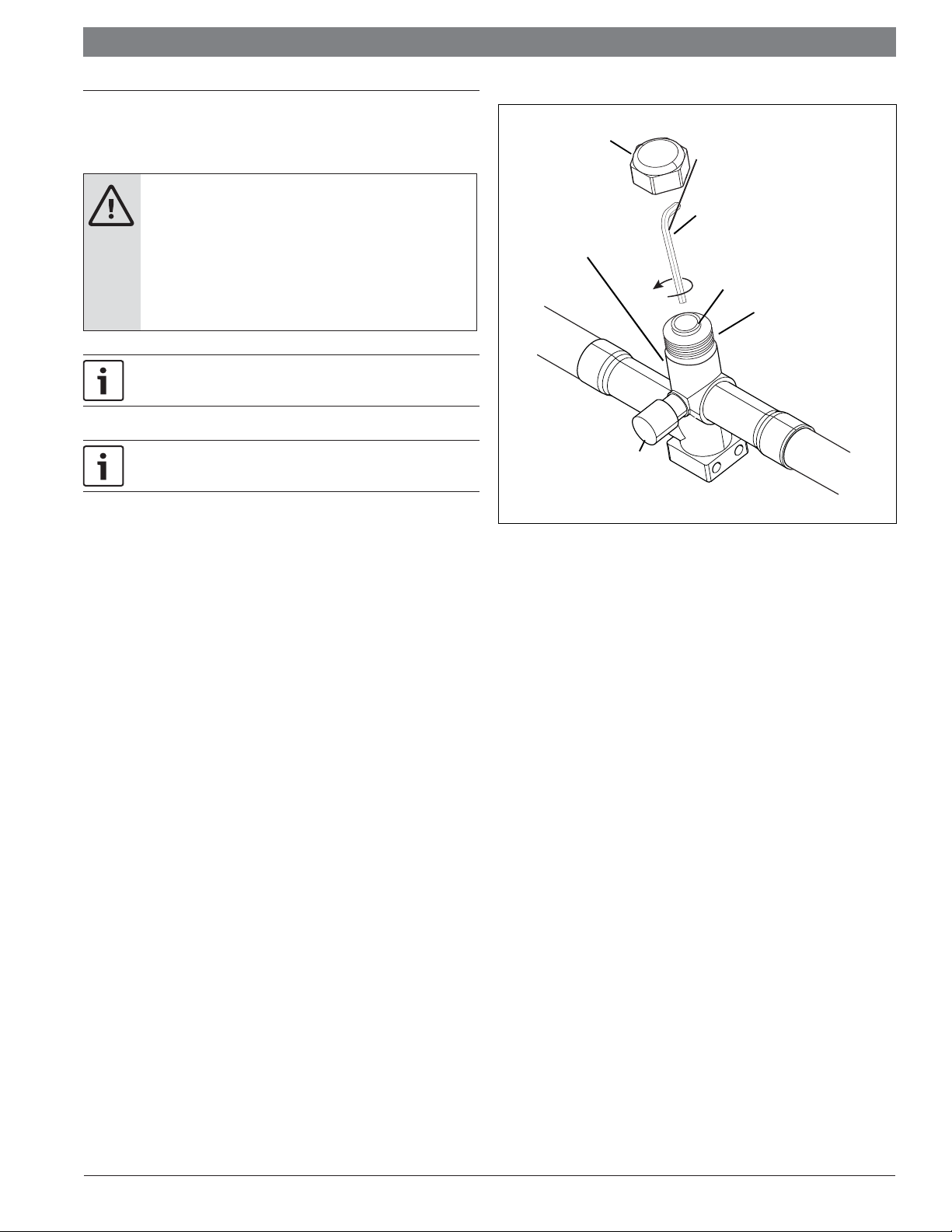
10 Service valves
10.1 Open the service valves
WARNING:
Extreme caution should be exercised when opening the
Liquid Line Service Valve. Turn counterclock wise until the
valve stem just touches the rolled edge. No torque is required.
Failure to follow this warning will result in abrupt release
of system charge and may result in personal injury and /or
property damage.
Leak check and evacuation must be com pleted before opening the service
valves.
The Suction Service Valve must be opened fi rst BEFORE opening the
Liquid Service Valve!
1. Remove service valve cap (Fig 24).
2. Fully insert hex wrench into the stem and back out counterclockwise until valve
stem just touches the rolled edge (approximately five (5) turns.)
Figure 24
Cap
Unit S ide
of Service
Val ve
Serv ice Port
5/16” Hex Wrench
for Suction Service Valve
3/16” Hex Wrench
for Liquid Service Valve
Roll ed Edge to
Capti vate Stem
Hex Headed
Val ve Sy st em
3. Replace the valve stem cap to prevent leaks. Tighten finger tight plus an
additional 1/6 turn.
4. Repeat STEPS 1 - 3 for Liquid Service Valve.
12.2016 | Bosch Thermotechnology Corp.Data subject to change
 Loading...