

Bosch BORECTWODWRH818 Installation manual

Installation instructions ................. 2
Instructions d’installation ..................... 14
Instrucciones de instalación ................. 26
HOODS HCP30651UC, HCP36651UC,
HCP80641UC
Hotte aspirante HCP30651UC, HCP36651UC, HCP80641UC
Campanas extractoras HCP30651UC, HCP36651UC, HCP80641UC

Table of Contents
Installation instructions
Safety Definitions .......................................................... 3
IMPORTANT SAFETY INSTRUCTIONS ........................ 4
General notes ........................................................................ 4
Fire Safety .............................................................................. 4
Burn Prevention .................................................................... 5
Child Safety ........................................................................... 5
Cleaning Safety ..................................................................... 6
Safe use ................................................................................. 6
Proper Installation and Maintenance ................................ 6
State of California Proposition 65 Warnings ................... 7
Causes for damages ..................................................... 7
Protecting the environment .......................................... 7
General notes ................................................................. 7
Fan operation ........................................................................ 7
Ventilation line ....................................................................... 7
Electrical connection ........................................................... 8
Before You Begin ........................................................... 8
Tools and Parts Needed ..................................................... 8
Parts Included ....................................................................... 8
Appliance dimensions ......................................................... 9
Safety clearances ................................................................. 9
Fan operation ........................................................................ 9
Ventilation line ....................................................................... 9
Checking the wall .............................................................. 10
Installation Procedure ................................................. 10
Preparing the installation ................................................. 10
Fitting the wall retainer ..................................................... 10
Making the ceiling breakthrough .................................... 10
Making the wall breakthrough ........................................ 10
Mounting the back-pressure flap .................................... 11
Mounting the recirculation model
(only for circulating-air mode) ......................................... 11
Connect Electrical Supply ................................................ 12
Attaching flue duct ............................................................ 12
Removing the appliance .................................................. 13
Produktinfo.
Additional information on products, accessories,
replacement parts and services can be found at
www.bosch-home.com and in the online shop
www.bosch-home.com/us/store
2
Safety Definitions
9 WARNING
This indicates that death or serious injuries may
occur as a result of non-observance of this warning.
9 CAUTION
This indicates that minor or moderate injuries may
occur as a result of non-observance of this warning.
NOTICE: This indicates that damage to the appliance or property may occur as a result of non-compliance with this advisory.
Note: This alerts you to important information and/or tips.
3
IMPORTANT SAFETY INSTRUCTIONS
READ AND SAVE THESE INSTRUCTIONS
IMPORTANT SAFETY INS READ AND SAVE THESE INSTRUCTIONS
WARNING
Fire Safety
When properly cared for, your new appliance has been
designed to be safe and reliable. Read all instructions
carefully before use. These precautions will reduce the
risk of burns, electric shock, fire, and injury to persons.
When using kitchen appliances, basic safety precautions
must be followed, including those in the following pages.
General notes
Examine the appliance after unpacking it. In the event of
transport damage, do not plug it in.
WARNING
TO REDUCE THE RISK OF FIRE, ELECTRIC SHOCK, OR
INJURY TO PERSONS, OBSERVE THE FOLLOWING:
Use this unit only in the manner intended by the
manufacturer. If you have questions, contact the
manufacturer.
Before servicing or cleaning unit, switch power off at
service panel and lock the service panel to prevent
power from being switched on accidentally.
When the service panel cannot be locked, securely
fasten a prominent warning device, such as a tag,
to the service panel.
WARNING
WARNING – TO REDUCE THE RISK OF FIRE, ELECTRIC SHOCK, OR INJURY TO PERSONS, OBSERVE THE FOLLOWING
Installation work and electrical wiring must be done by
qualified person(s) in accordance with all applicable
codes and standards, including fire-rated construction.
Sufficient air is needed for proper combustion and
exhausting of gases through the flue (chimney) of fuel
burning equipment to prevent back -drafting. Follow the
heating equipment manufacturer’s guideline and safety
standards such as those published by the National Fire
Protection Association (NFPA), and the American
Society for Heating, Refrigeration and Air Conditioning
Engineers (ASHRAE), and the local code authorities.
When cutting or drilling into wall or ceiling, do not
damage electrical wiring and other hidden utilities.
Ducted fans must always be vented to the outdoors.
WARNING
To reduce risk of fire and to properly exhaust air, be sure
to duct air outside. Do not vent exhaust air into spaces
within walls, ceilings, attics, crawl spaces or garages.
WARNING
To reduce the risk of fire, use only metal ductwork.
Always have a working smoke detector near the kitchen.
WARNING
TO REDUCE THE RISK OF A RANGE TOP GREASE FIRE:
a.
Never leave surface units unattended at high settings.
Boil overs cause smoking and greasy spillovers that
may ignite. Heat oils slowly on low or medium settings.
b.
Always turn hood ON when cooking at high heat or
when flambéing food (i.e. Crepes Suzette, Cherries
Jubilee, Peppercorn Beef Flambé).
c.
Clean ventilating fans frequently. Grease should not be
allowed to accumulate on fan or filter.
d.
Use proper pan size. Always use cookware
appropriate for the size of the surface element.
Do not flambé under the extractor hood or work with a
naked flame. When switched on, the extractor hood
draws flames into the filter. There is a risk of fire due to
deposits on the grease filter!
CAUTION
For general ventilating use only. Do not use to exhaust
hazardous or explosive materials and vapors.
In the event that personal clothing or hair catches fire,
drop and roll immediately to extinguish flames.
Smother flames from food fires other than grease fires
with baking soda. Never use water on cooking fires.
This appliance is not intended for operation with an
external clock timer or a remote control.
Do not use extension cord for installation.
Have an appropriate fire extinguisher available, nearby,
highly visible, and easily accessible near the appliance.
4
9 IMPORTANT SAFETY INSTRUCTIONS
READ AND SAVE THESE INSTRUCTIONS
WARNING
TO REDUCE THE RISK OF INJURY TO PERSONS IN THE EVENT OF A RANGE TOP GREASE FIRE, OBSERVE THE FOLLOWING:
SMOTHER FLAMES with a close-fitting lid, cookie
sheet, or metal tray, then turn off the burner. BE
CAREFUL TO PREVENT BURNS. If the flames do not
go out immediately, EVACUATE AND CALL THE FIRE
DEPARTMENT.
NEVER PICK UP A FLAMING PAN – You may be
burned.
DO NOT USE WATER, including wet dishcloths or
towels – a violent steam explosion may result.
Use an extinguisher ONLY if:
- You know you have a Class ABC extinguisher, and
you already know how to operate it.
- The fire is small and contained in the area where it
started.
- The fire department is being called.
a
Based on “Kitchen Fire Safety Tips” published by NFPA.
Whenever possible, do not operate the ventilation system
during a cooktop fire. However, do not reach through fire
to turn it off.
a
WARNING
RISK OF FIRE
Grease deposits in the grease filter can ignite.
Clean the grease filter at least every two months.
Never operate the appliance without the grease filter.
WARNING
RISK OF FIRE
Grease deposits in the grease filter can catch fire. Never
work with a naked flame near the appliance (e.g.
flambéing). Install the unit near a heat-producing
appliance for solid fuels (e.g. wood or coal) only if there
is a closed, non-detachable cover. There must be no
flying sparks.
Burn Prevention
WARNING
RISK OF BURNS
The accessible parts get hot during operation. Never
touch hot parts. Keep children away.
WARNING
RISK OF FIRE
When gas burners are in operation without any cookware
placed on them, they can build up a lot of heat. A
ventilation appliance installed above the cooker may
become damaged or catch fire. Only operate the gas
burners with cookware on them.
WARNING
RISK OF FIRE
During simultaneous use of multiple gas cooktops, a
great deal of heat is created. A ventilation device located
above it can become damaged or catch fire. Never use
two gas cooktops together at maximum heat for longer
than 15 minutes. One large burner with over 17,000 Btu/
hr (5 kW) (wok) is equal to the wattage of two gas
burners.
WARNING
RISK OF FIRE
Hot oil and fat catch fire fast. Never leave hot oil and fat
unsupervised. Never extinguish a fire with water. Switch
off the cooking position. Suffocate flames carefully with a
lid, a fire blanket or similar.
Child Safety
When children become old enough to use the appliance,
it is the responsibility of the parents or legal guardians to
ensure that they are instructed in safe practices by
qualified persons.
Remove all tape and packaging before using the
appliance. Destroy the packaging after unpacking the
appliance. Never allow children to play with packaging
material.
Do not allow anyone to climb, stand, lean, sit, or hang on
any part of an appliance, especially a door, warming
drawer, or storage drawer. This can damage the
appliance, and the unit may tip over, potentially causing
severe injury.
Do not allow children to use this appliance unless closely
supervised by an adult. Children and pets should not be
left alone or unattended in the area where the appliance
is in use. They should never be allowed to play in its
vicinity, whether or not the appliance is in use.
CAUTION
Items of interest to children should not be stored in an
appliance, in cabinets above an appliance or on the
backsplash. Children climbing on an appliance to reach
items could be seriously injured.
5
9 IMPORTANT SAFETY INSTRUCTIONS
READ AND SAVE THESE INSTRUCTIONS
Cleaning Safety
WARNING
Be sure the entire appliance (including the grease filters
and light bulbs, if applicable) has cooled and grease has
solidified before attempting to clean any part of the
appliance.
Do not use steam cleaners to clean the appliance.
Safe use
WARNING
Do not repair, replace or remove any part of the
appliance unless specifically recommended in the
manuals. Improper installation, service or maintenance
can cause injury or property damage. Refer to this
manual for guidance. All other servicing should be done
by an authorized technician.
WARNING
RISK OF INJURY
Items placed on the appliance may fall down. Do not
place any objects on the appliance.
Proper Installation and Maintenance
Have the installer show you the location of the circuit
breaker or fuse. Mark it for easy reference.
This appliance must be properly installed and grounded
by a qualified technician. Connect only to properly
grounded outlet. Refer to Installation Instructions for
details.
This appliance is intended for normal family household
use only. It is not approved for outdoor use. See the
Warranty. If you have any questions, contact the
manufacturer.
Do not store or use corrosive chemicals, vapors,
flammables or nonfood products in or near this
appliance. It is specifically designed for use when
heating or cooking food. The use of corrosive chemicals
in heating or cleaning will damage the appliance and
could result in injury.
Do not operate this appliance if it is not working properly,
or if it has been damaged. Contact an authorized
servicer.
Do not repair or replace any part of the appliance unless
specifically recommended in this manual. Refer all
servicing to a factory authorized service center.
CAUTION
Turn power off at breaker before removing a damaged
bulb. Do not touch the bulbs immediately after use. The
bulbs will remain hot for several minutes.
WARNING
Make sure the appliance and lights are cool and power
to the appliance has been turned off before replacing the
light bulb(s). Failure to do so could result in electrical
shock or burns.The lenses (if equipped) must be in place
when using the appliance.The lenses (if equipped) serve
to protect the light bulb from breaking.The lenses (if
equipped) are made of glass. Handle carefully to avoid
breaking. Broken glass can cause an injury.
Hidden surfaces may have sharp edges. Use caution
when reaching behind or under appliance.
WARNING
When the hood is operated in exhaust-air mode
simultaneously with a different burner which also makes
use of the same chimney (such as gas, oil or coal-fired
heaters, continuous-flow heaters, hot-water boilers) care
must be taken to ensure that there is an adequate supply
of fresh air which will be needed by the burner for
combustion.
Safe operation is possible provided that the under
pressure in the room where the burner is installed does
not exceed 4 Pa (0.04 mbar).
This can be achieved if combustion air can flow through
non-lockable openings, e.g. in doors, windows and via
the air-intake/exhaust-air wall box or by other technical
measures, such as reciprocal interlocking, etc.
WARNING
Avoid carbon monoxide poisoning – Provide adequate
air intake so combustion gases are not drawn back into
the room.
An air-intake/exhaust-air wall box by itself is no
guarantee that the limiting value will not be exceeded.
Note: When assessing the overall requirement, the combined ventilation system for the entire household must be taken into consideration. This rule does not apply to the use of cooking appliances, such as cooktops and ovens.
CAUTION
Grease left on filters can remelt and move into the vent.
6
State of California Proposition 65
Warning
WARNING
This product can expose you to chemicals including
vinyl chloride, which is known to the State of California
to cause cancer and birth defects or other reproductive
harm.
For more information go to www.P65Warnings.ca.gov.
Causes for damages
9 CAUTION
Risk of damage due to corrosion. Always turn
appliance on when cooking to avoid condensation
buildup. Condensation can lead to corrosion
damages.
Always replace burnt out bulbs immediately to avoid an
overload of the remaining bulbs.
Protecting the environment
Unpack the appliance and dispose of the packaging in
line with environmental requirements.
General notes
Fan operation
Note: Ventilation may not exit through an already
operational smoke or exhaust chimney, nor a duct used
for ventilating furnace installation areas.
If the ventilation is intended to pass through a smoke
or exhaust that is not in operation, the responsible
area heating inspector must give approval.
If the ventilation passes through an external wall, use a
telescope wall sleeve.
Risk of damage due to the presence of humidity into the
electronic circuitry. Never clean operator controls with a
wet cloth.
Surface damage due to incorrect cleaning. Clean
stainless steel surfaces in the grain direction only. Do not
use any stainless steel cleaners for operator controls.
Surface damage due to strong or abrasive cleaning
agents. Never use strong and abrasive cleaning agents.
Risk of damage from condensation back flow. Install
exhaust vent at a slight downward slope away from the
appliance (1° slope).
Round pipes
An inner diameter of 8 ” (203 mm) is recommended.
Ventilation line
Note: The manufacturer is not responsible for any issues
associated with the pipe section.
The device achieves its optimum performance by
means of a short, straight exhaust air pipe and as
large a pipe diameter as possible.
The optimum extraction performance is not achieved
and fan noise is increased if exhaust air pipes are long
and rough and if there is a large number of pipe bends
or diameters less than 8” (203 mm).
The pipes or hoses for laying the exhaust air line must
consist of non-combustible material.
7
Electrical connection
9 WARNING
RISK OF ELECTRIC SHOCK
Parts inside the appliance can have sharp edges.
The connection cable can be damaged. Do not
bend or pinch connection cables during installation.
Before connecting the appliance, check the household
installation. Ensure sufficient fuse protection of the
household installation. The voltage and frequency of the
appliance must match the electrical installation (see
rating plate).
The appliance complies with protection class 1 and must
only be operated in conjunction with a protective
conductor terminal.
An all-pole isolating switch with at least a 3 mm contact
gap must be fitted in the installation. This must remain
accessible after installation.
Only a qualified electrician who takes the appropriate
regulations into account may lay or replace the
connecting cable.
Follow all valid standards and laws.
Ensure that the electrical connection meets the
requirements of the latest version of all applicable
standards and laws in the appropriate country, especially
the following standards: National Electrical Code, ANSI/
NFPA 70*, or CSA Standards C22.1-94, Canadian
Electrical Code, Part 1 and C22.2 No.0-M91**.
Have a qualified electrical technician check the
grounding of the appliance.
Do not ground to a gas line.
No fuse protection in the neutral or grounding circuit.
Keep the installation instructions. Only connect the
appliance with a copper conductor. If possible, connect
the appliance to a metal cable guide directly to the fuse
box.
Ensure that the wire diameter meets the requirements of
the latest version of all applicable standards and laws in
the appropriate country, especially the following
standards: National Electrical Code, ANSI/NFPA 70*, or
CSA Standards C22.1-94, Canadian Electrical Code, Part
1 and C22.2 No.0-M91**.
Put a protecting hose that is listed in the U.L. or C.S.A. on
both ends of the connecting cable, that is, on the
appliance and on the fuse box.
For copies of the standards listed, contact:
* National Fire Protection Association Batterymarch Park
Quincy, Massachusetts 02269
** CSA International 8501 East Pleasant Valley Road
Cleveland, Ohio 44131-5575
Before You Begin
Tools and Parts Needed
Measuring tape
Pencil
Phillips screwdriver (Posidrive) #2
Drill with the following bits: 5/16" (7.9 mm) and 3/8"
(9.5 mm)
Spirit-level
Aluminum tape (DO NOT use insulating tape)
Exhaust channel (configuration depends on the
installation situation)
Additional sheet metal screws (if necessary for
installation of the exhaust air duct)
Saw
Parts Included
Extractor hood with fan, back-pressure flap
Lamp, already installed
Metal grease filter
Flue duct
Drill template
1x angle bracket for the flue duct
Installation manual and instructions for use
6x screws, 5x45 mm
8x screws, 4x8 mm
2x washers
2x hollow wall plugs, 8x40 mm
4x hollow wall plugs, 10x50 mm
Torx adapter, 10 & 20
8
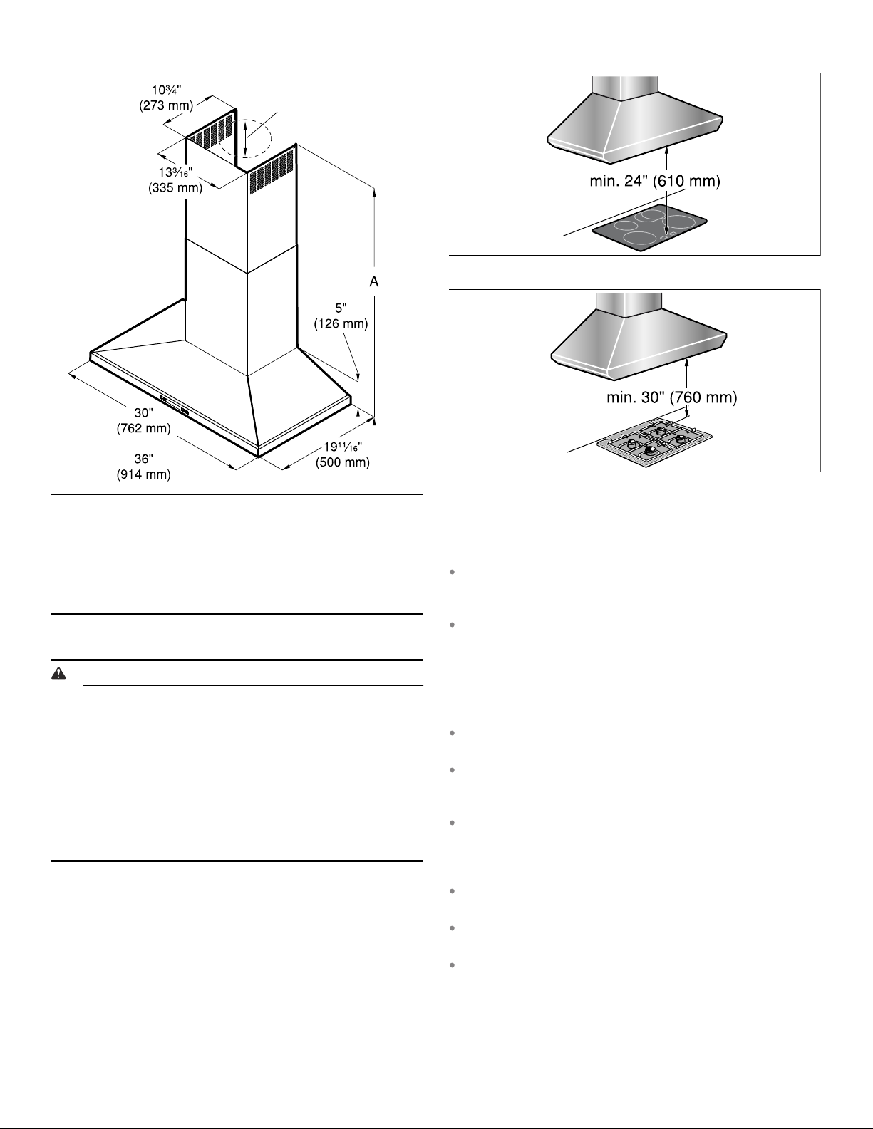
Appliance dimensions
Electrical cooktop
77/8”
(200 mm)
Gas cooktop
A Only for circulating-air mode:
*Max. 42 9/16" (1081 mm)
*Min. 28 1/4" (718 mm)
Only for ducted operation:
*Max. 38 7/8" (988 mm)
*Min. 24 9/16" (625 mm)
Safety clearances
WARNING
RISK OF FIRE
Grease deposits in the grease filter can catch fire.
The given safety clearance must be observed to
avoid heat buildup. Observe the specifications for
your cooking appliance. If gas and electric cooktops
are used together, the largest given clearance
applies.
The appliance may only be installed directly next to
a cabinet or wall on one side. The wall or cabinet
clearance must be at least 2" (50 mm).
The clearance between the shelf on the cooktop and the
bottom of the extractor hood may not be less than 24"
(610 mm) in the case of electric cooktops and 30"
(760 mm) in case of gas or combined ranges.
If the installation instructions for the gas cooking
appliance specify a larger distance, this must be taken
into account.
Fan operation
Note: Ventilation may not exit through an already
operational smoke or exhaust chimney, nor a duct used
for ventilating furnace installation areas.
If the ventilation is intended to pass through a smoke
or exhaust that is not in operation, the responsible
area heating inspector must give approval.
If the ventilation passes through an external wall, use a
telescope wall sleeve.
Ventilation line
Note: The device manufacturer does not assume any
warranty for complaints attributable to the pipe section.
The ventilation opening and the exhaust air ducts must
be made according to the local circumstances.
The device achieves its optimum performance by
means of a short, straight exhaust air pipe and as
large a pipe diameter as possible.
As a result of long rough exhaust air pipes, many pipe
bends or too-small diameters, the optimum extraction
performance is not achieved and fan noise is
increased.
The pipes or hoses for laying the exhaust air line must
consist of non-combustible material.
Smooth the connection area of the pipes before
installation.
Seal the connection points of the pipes appropriately.
9
Round pipes
An inner diameter of Ø 8" (203 mm) is recommended.
Installation Procedure
Checking the wall
The wall must be level, vertical and adequately loadbearing.
The depth of the bore holes must be the same length
as the screws. The wall plugs must have a secure grip.
The enclosed screws and wall plugs are suitable for
solid brickwork. Suitable fasteners must be used for
other structures.
9 CAUTION
Ensure that there are no electric wires, gas or water
pipes in the area where holes are to be made.
If you are not sure, consult a qualified installer
Preparing the installation
1.
Mark a vertical center line on the wall from the ceiling to the lower edge of the extractor hood.
2.
Align the drill template on the center line and the bottom edge of the extractor hood and glue on.
3.
Mark positions for the screws and the contour of the attachment area.
4.
Mark holes for the flue's angle brackets. The center of the angle bracket is marked with a hole. Place the angle brackets in the center of the center line, align them horizontally and mark the positions of the holes.
Fitting the wall retainer
1.
Drill holes with Ø 5/16" (7.9 mm) for the angle bracket.
2.
Press in the wall plugs flush with the wall.
3.
Screw screws (5x34 mm) into the wall plugs by hand in order to spread the plugs apart.
4.
Unscrew screws.
5.
Screw on the angle bracket for the flue duct.
Mounting the extractor hood on the wall
9 WARNING
RISK OF INJURY
The appliance is heavy. To move the appliance, 2
people are required. Use only suitable tools and
equipment.
1.
Initially remove the protective foil from the back of the appliance and, following installation, remove foil completely.
2.
Mark the upper holes on the wall. Note: Ensure that the holes are horizontal and aligned
centered on the center line.
3.
Drill the upper holes. Adhere to a distance of 1/4" (6 mm) between the wall and screw head.
4.
Remove grease filters.
5.
Hang the extractor hood on the upper screws on the wall.
6.
Mark holes for the lower holes.
7.
Remove the extractor hood from the wall.
8.
Drill the lower holes.
9.
Hang the extractor hood on the upper screws on the wall.
10.
Tighten the upper and lower screws by hand.
Making the ceiling breakthrough
1.
Using a spirit level, extend the center line of the drill template to the ceiling.
2.
Mark the ceiling breakthrough (Ø 8 1/2" (216 mm)) at least 4 5/8" (117 mm) away from the wall.
Making the wall breakthrough
1.
Using a spirit level, extend the center line of the drill template to the ceiling.
2.
Depending on the curved section of the wall breakthrough (Ø 8 1/2" (216 mm)) mark at least 26 1/ 2" (660 mm) above the bottom edge of the extractor hood.
10
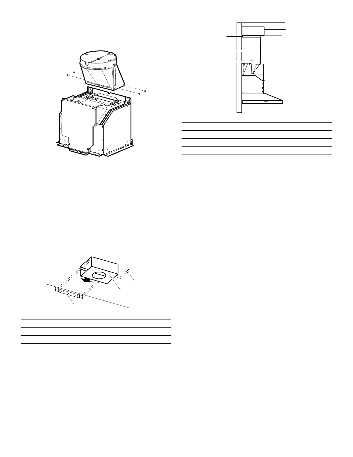
Mounting the back-pressure flap
Using 4 screws (4x8 mm), attach the back-pressure flap
to the extractor hood.
Connecting the air extractor (only for ducted operation)
Note: If an aluminum pipe is used, smooth the
connection area beforehand.
1.
Attach exhaust air pipe and seal.
2.
Check whether the back-pressure flap works.
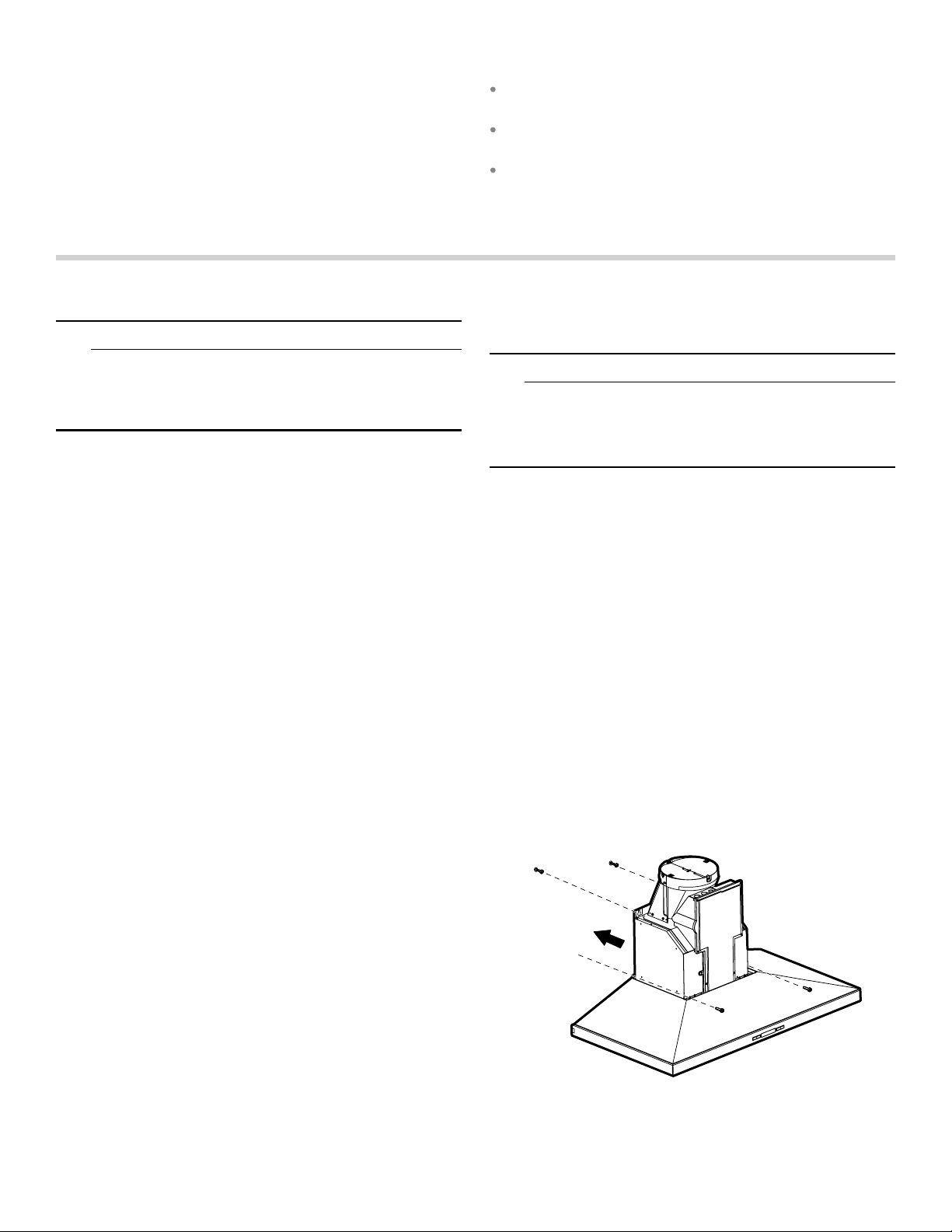
Mounting the recirculation model (only for circulating-air mode)
1.
Use 4 screws (4x8 mm) to screw the housing to the angle bracket.
$
%
&
'
A Recirculation module
B Clamps
C Flue duct
D Exhaust air duct
3.
Shorten the exhaust air pipe to the length measured.
4.
Remove the recirculation module.
5.
Push the exhaust air pipe onto the bottom side of the recirculation module.
6.
Position the recirculation module with exhaust air pipe over the air extraction duct of the extractor hood.
7.
Use 4 screws to fasten the recirculation module to the angle bracket.
8.
Secure connections with clamps.
[
$
%
&
A Screws
B Recirculation module
C Angle bracket
2.
Measure the distance (x) between the bottom edge of the housing for the recirculation module and the bottom edge of the back-pressure flap.
11
Connect Electrical Supply
9 WARNING
RISK OF ELECTRIC SHOCK
Before wiring the appliance, interrupt the main
electrical circuit at the electrical control cabinet. A
circuit with 120 VAC, 15 or 20 Ampere is required.
Grounding notes: this appliance is equipped with a
distributor box with 3 cables. Use the green-yellow
cable for grounding the appliance. Connect the
green-yellow cable to the grounding cable on the
house connection to prevent electric sthock. Do not
under any circumstances damage or remove the
green-yellow cable. Non-adherence can cause
deadly injuries or electric shock.
Installation work and electrical wiring must be done
by qualified person(s) in accordance with all
applicable codes and standards, including
fire-rated construction.
1.
Remove the left cable passage and the cover of the motor controller. Fasten the connecting piece for the installation pipe (listed in cULUS) to the cable passage.
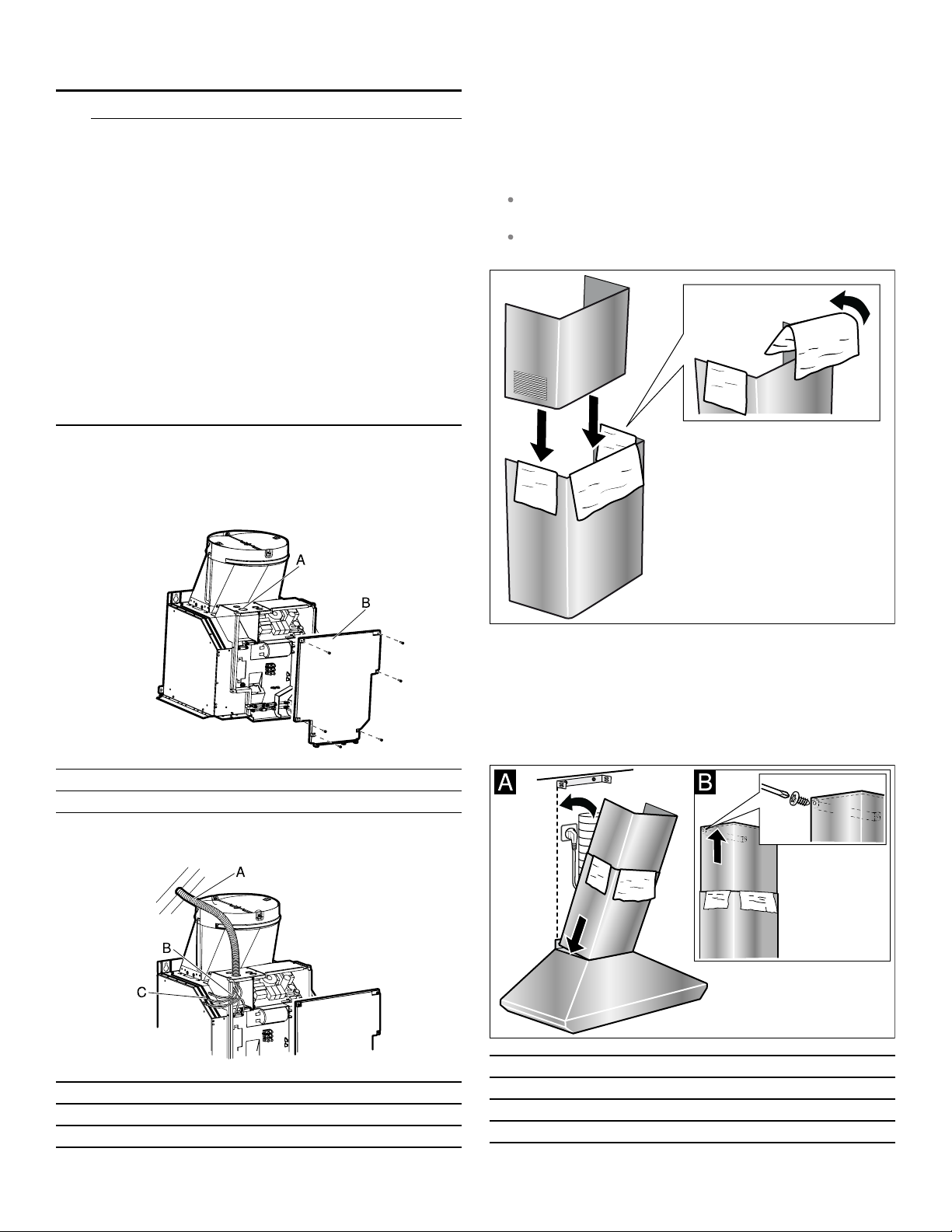
Attaching flue duct
Hidden surfaces may have sharp edges. Use caution
when reaching behind or under appliance.
1.
Remove the protective foil from both flue ducts.
2.
Push one flue duct into the other.
Notes
To prevent scratches, lay paper over the edges of
the lower flue duct to protect the surface.
For ducted operation, turn the upper flue duct so
that the ventilation slots point downward.
A Cable passage
B Cover of the motor controller
2.
Connect 1/2" (12.7 mm) installation pipe to motor controller.
A Installation pipe
B Power connection
C Cable connector listed in UL
3.
Remove the protective foil from the extractor hood.
4.
Place flue ducts on the appliance.
5.
Push the inner flue duct upwards and attach it to the angle brackets on the left and right.
6.
Screw the flue duct to the sides of the angle bracket using two screws.
A Upper flue duct
B Lower flue duct
C Screws
D Angle bracket
12
 Loading...