

Page 1
Data sheet
BNO055
Intelligent 9-axis absolute orientation sensor
BNO055: data sheet
Document revision
1.4
Document release date
June 2016
Document number
BST-BNO055-DS000-14
Technical reference code(s)
0 273 141 209
Notes
Data in this document are subject to change without notice. Product
photos and pictures are for illustration purposes only and may differ from
the real product’s appearance.
User Motion
• Quaternion
• Linear Acceleration
• Rotation
• Gravity
• Robust Heading
Bosch Sensortec
Page 2

BNO055
Data sheet
Page 2
BNO055
INTELLIGENT ABSOLUTE ORIENTATION SENSOR, 9-AXIS SENSOR FUSION
ALL-IN-ONE WINDOWS 8.x COMPLIANT SENSOR HUB
Basic Description
Key features:
Outputs fused sensor data Quaternion, Euler angles, Rotation vector,
Linear acceleration, Gravity, Heading
3 sensors in one device an advanced triaxial 16bit gyroscope, a versatile,
leading edge triaxial 14bit accelerometer and a
full performance geomagnetic sensor
Small package LGA package 28 pins
Footprint 3.8 x 5.2 mm², height 1.13 mm²
Power Management Intelligent Power Management: normal,
low power and suspend mode available
Common voltage supplies V
Digital interface HID-I2C (Windows 8 compatible), I²C, UART
V
Consumer electronics suite MSL1, RoHS compliant, halogen-free
Key features of integrated sensors:
voltage range: 2.4V to 3.6V
DD
voltage range: 1.7V to 3.6V
DDIO
Operating temperature: -40°C ... +85°C
Accelerometer features
Programmable functionality Acceleration ranges ±2g/±4g/±8g/±16g
Low-pass filter bandwidths 1kHz - <8Hz
Operation modes:
- Normal
- Suspend
- Low power
- Standby
- Deep suspend
On-chip interrupt controller Motion-triggered interrupt-signal generation for
- any-motion (slope) detection
- slow or no motion recognition
- high-g detection
BST-BNO055-DS000-14 | Revision 1.4 | June 2016 Bosch Sensortec
© Bosch Sensortec GmbH reserves all rights even in the event of industrial property rights. We reserve all rights of disposal su ch as copying and passing on
to third parties. BOSCH and the symbol are registered trademarks of Robert Bosch GmbH, Germany.
Note: Specifications within this document are subject to change without notice.
Page 3

BNO055
Data sheet
Page 3
Gyroscope features
Programmable functionality Ranges switchable from ±125°/s to ±2000°/s
Low-pass filter bandwidths 523Hz - 12Hz
Operation modes:
- Normal
- Fast power up
- Deep suspend
- Suspend
- Advanced power save
On-chip interrupt controller Motion-triggered interrupt-signal generation for
- any-motion (slope) detection
- high rate
Magnetometer features
Flexible functionality Magnetic field range typical ±1300µT (x-, y-axis);
±2500µT (z-axis)
Magnetic field resolution of ~0.3µT
Operating modes:
- Low power
- Regular
- Enhanced regular
- High Accuracy
Power modes:
- Normal
- Sleep
- Suspend
- Force
Typical applications
Navigation
Robotics
Fitness and well-being
Augmented reality
Context awareness
Tablets and ultra-books
BST-BNO055-DS000-14 | Revision 1.4 | June 2016 Bosch Sensortec
© Bosch Sensortec GmbH reserves all rights even in the event of industrial property rights. We reserve all rights of disposal su ch as copying and passing on
to third parties. BOSCH and the symbol are registered trademarks of Robert Bosch GmbH, Germany.
Note: Specifications within this document are subject to change without notice.
Page 4

BNO055
Data sheet
Page 4
General description
The BNO055 is a System in Package (SiP), integrating a triaxial 14-bit accelerometer, a
triaxial 16-bit gyroscope with a range of ±2000 degrees per second, a triaxial geomagnetic
sensor and a 32-bit cortex M0+ microcontroller running Bosch Sensortec sensor fusion
software, in a single package.
The corresponding chip-sets are integrated into one single 28-pin LGA 3.8mm x 5.2mm x
1.1 mm housing. For optimum system integration the BNO055 is equipped with digital bidirectional I2C and UART interfaces. The I2C interface can be programmed to run with the
HID-I2C protocol turning the BNO055 into a plug-and-play sensor hub solution for devices
running the Windows 8.0 or 8.1 operating system.
BST-BNO055-DS000-14 | Revision 1.4 | June 2016 Bosch Sensortec
© Bosch Sensortec GmbH reserves all rights even in the event of industrial property rights. We reserve all rights of disposal su ch as copying and passing on
to third parties. BOSCH and the symbol are registered trademarks of Robert Bosch GmbH, Germany.
Note: Specifications within this document are subject to change without notice.
Page 5

BNO055
Data sheet
Page 5
Contents
BASIC DESCRIPTION ........................................................................................................... 2
SPECIFICATION .................................................................................................................. 12
1.1 ELECTRICAL SPECIFICATION .......................................................................................... 12
1.2 ELECTRICAL AND PHYSICAL CHARACTERISTICS, MEASUREMENT PERFORMANCE ................ 13
2. ABSOLUTE MAXIMUM RATINGS .................................................................................. 17
3. FUNCTIONAL DESCRIPTION ......................................................................................... 18
3.1 ARCHITECTURE ............................................................................................................. 18
3.2 POWER MANAGEMENT ................................................................................................... 18
3.2.1 NORMAL MODE ....................................................................................................................... 19
3.2.2 LOW POWER MODE ................................................................................................................. 19
3.2.3 SUSPEND MODE ..................................................................................................................... 20
3.3 OPERATION MODES ...................................................................................................... 20
3.3.1 CONFIG MODE ........................................................................................................................ 22
3.3.2 NON-FUSION MODES .............................................................................................................. 22
3.3.3 FUSION MODES ....................................................................................................................... 22
3.4 AXIS REMAP.................................................................................................................. 24
3.5 SENSOR CONFIGURATION.............................................................................................. 26
3.5.1 DEFAULT SENSOR CONFIGURATION .......................................................................................... 26
3.5.2 ACCELEROMETER CONFIGURATION .......................................................................................... 27
3.5.3 GYROSCOPE CONFIGURATION .................................................................................................. 28
3.5.4 MAGNETOMETER CONFIGURATION............................................................................................ 29
3.6 OUTPUT DATA ............................................................................................................... 30
3.6.1 UNIT SELECTION...................................................................................................................... 30
3.6.2 DATA OUTPUT FORMAT ............................................................................................................ 30
3.6.3 FUSION OUTPUT DATA RATES .................................................................................................. 31
3.6.4 SENSOR CALIBRATION DATA ..................................................................................................... 31
3.6.5 OUTPUT DATA REGISTERS ....................................................................................................... 33
3.7 DATA REGISTER SHADOWING ......................................................................................... 37
3.8 INTERRUPTS ................................................................................................................. 38
3.8.1 INTERRUPT PIN ....................................................................................................................... 38
3.8.2 INTERRUPT SETTINGS ............................................................................................................. 38
3.9 SELF-TEST ................................................................................................................... 46
3.9.1 POWER ON SELF TEST (POST) ............................................................................................... 46
3.9.2 BUILD IN SELF TEST (BIST) ..................................................................................................... 46
3.10 BOOT LOADER ............................................................................................................ 46
3.11 CALIBRATION .............................................................................................................. 47
3.11.1 ACCELEROMETER CALIBRATION ............................................................................................. 47
3.11.2 GYROSCOPE CALIBRATION .................................................................................................... 47
3.11.3 MAGNETOMETER CALIBRATION .............................................................................................. 47
3.11.4 REUSE OF CALIBRATION PROFILE .......................................................................................... 48
BST-BNO055-DS000-14 | Revision 1.4 | June 2016 Bosch Sensortec
© Bosch Sensortec GmbH reserves all rights even in the event of industrial property rights. We reserve all rights of disposal su ch as copying and passing on
to third parties. BOSCH and the symbol are registered trademarks of Robert Bosch GmbH, Germany.
Note: Specifications within this document are subject to change without notice.
Page 6

BNO055
Data sheet
Page 6
4. REGISTER DESCRIPTION .............................................................................................. 49
4.1 GENERAL REMARKS ...................................................................................................... 49
4.2 REGISTER MAP ............................................................................................................. 50
4.2.1 REGISTER MAP PAGE 0 ........................................................................................................... 50
4.2.2 REGISTER MAP PAGE 1 ........................................................................................................... 53
4.3 REGISTER DESCRIPTION (PAGE 0).................................................................................. 54
4.3.1 CHIP_ID 0X00 ....................................................................................................................... 54
4.3.2 ACC_ID 0X01 ........................................................................................................................ 54
4.3.3 MAG_ID 0X02 ....................................................................................................................... 54
4.3.4 GYR_ID 0X03 ........................................................................................................................ 54
4.3.5 SW_REV_ID_LSB 0X04 ....................................................................................................... 55
4.3.6 SW_REV_ID_MSB 0X05 ...................................................................................................... 55
4.3.7 BL_REV_ID 0X06 .................................................................................................................. 55
4.3.8 PAGE ID 0X07 ....................................................................................................................... 55
4.3.9 ACC_DATA_X_LSB 0X08 ..................................................................................................... 56
4.3.10 ACC_DATA_X_MSB 0X09 .................................................................................................. 56
4.3.11 ACC_DATA_Y_LSB 0X0A .................................................................................................. 56
4.3.12 ACC_DATA_Y_MSB 0X0B ................................................................................................. 56
4.3.13 ACC_DATA_Z_LSB 0X0C .................................................................................................. 57
4.3.14 ACC_DATA_Z_MSB 0X0D ................................................................................................. 57
4.3.15 MAG_DATA_X_LSB 0X0E .................................................................................................. 57
4.3.16 MAG_DATA_X_MSB 0X0F ................................................................................................. 57
4.3.17 MAG_DATA_Y_LSB 0X10 .................................................................................................. 58
4.3.18 MAG_DATA_Y_MSB 0X11 ................................................................................................. 58
4.3.19 MAG_DATA_Z_LSB 0X12 .................................................................................................. 58
4.3.20 MAG_DATA_Z_MSB 0X13 ................................................................................................. 58
4.3.21 GYR_DATA_X_LSB 0X14 .................................................................................................. 59
4.3.22 GYR_DATA_X_MSB 0X15 ................................................................................................. 59
4.3.23 GYR_DATA_Y_LSB 0X16 .................................................................................................. 59
4.3.24 GYR_DATA_Y_MSB 0X17 ................................................................................................. 59
4.3.25 GYR_DATA_Z_LSB 0X18 ................................................................................................... 60
4.3.26 GYR_DATA_Z_MSB 0X19 .................................................................................................. 60
4.3.27 EUL_DATA_X_LSB 0X1A ................................................................................................... 60
4.3.28 EUL_DATA_X_MSB 0X1B .................................................................................................. 60
4.3.29 EUL_DATA_Y_LSB 0X1C ................................................................................................... 61
4.3.30 EUL_DATA_Y_MSB 0X1D .................................................................................................. 61
4.3.31 EUL_DATA_Z_LSB 0X1E ................................................................................................... 61
4.3.32 EUL_DATA_Z_MSB 0X1F .................................................................................................. 61
4.3.33 QUA_DATA_W_LSB 0X20 ................................................................................................. 62
4.3.34 QUA_DATA_W_MSB 0X21 ................................................................................................ 62
4.3.35 QUA_DATA_X_LSB 0X22 .................................................................................................. 62
4.3.36 QUA_DATA_X_MSB 0X23 ................................................................................................. 62
4.3.37 QUA_DATA_Y_LSB 0X24 .................................................................................................. 63
4.3.38 QUA_DATA_Y_MSB 0X25 ................................................................................................. 63
4.3.39 QUA_DATA_Z_LSB 0X26 ................................................................................................... 63
4.3.40 QUA_DATA_Z_MSB 0X27 .................................................................................................. 63
4.3.41 LIA_DATA_X_LSB 0X28 ..................................................................................................... 64
4.3.42 LIA_DATA_X_MSB 0X29 .................................................................................................... 64
4.3.43 LIA_DATA_Y_LSB 0X2A .................................................................................................... 64
4.3.44 LIA_DATA_Y_MSB 0X2B ................................................................................................... 64
4.3.45 LIA_DATA_Z_LSB 0X2C .................................................................................................... 65
4.3.46 LIA_DATA_Z_MSB 0X2D ................................................................................................... 65
4.3.47 GRV_DATA_X_LSB 0X2E .................................................................................................. 65
4.3.48 GRV_DATA_X_MSB 0X2F ................................................................................................. 65
4.3.49 GRV_DATA_Y_LSB 0X30 .................................................................................................. 66
4.3.50 GRV_DATA_Y_MSB 0X31 ................................................................................................. 66
BST-BNO055-DS000-14 | Revision 1.4 | June 2016 Bosch Sensortec
© Bosch Sensortec GmbH reserves all rights even in the event of industrial property rights. We reserve all rights of disposal su ch as copying and passing on
to third parties. BOSCH and the symbol are registered trademarks of Robert Bosch GmbH, Germany.
Note: Specifications within this document are subject to change without notice.
Page 7

BNO055
Data sheet
Page 7
4.3.51 GRV_DATA_Z_LSB 0X32 ................................................................................................... 66
4.3.52 GRV_DATA_Z_MSB 0X33 .................................................................................................. 66
4.3.53 TEMP 0X34 ......................................................................................................................... 67
4.3.54 CALIB_STAT 0X35.............................................................................................................. 67
4.3.55 ST_RESULT 0X36 .............................................................................................................. 67
4.3.56 INT_STA 0X37 .................................................................................................................... 68
4.3.57 SYS_CLK_STATUS 0X38 ................................................................................................... 68
4.3.58 SYS_STATUS 0X39 ............................................................................................................ 68
4.3.59 SYS_ERR 0X3A .................................................................................................................. 69
4.3.60 UNIT_SEL 0X3B.................................................................................................................. 69
4.3.61 OPR_MODE 0X3D .............................................................................................................. 70
4.3.62 PWR_MODE 0X3E.............................................................................................................. 70
4.3.63 SYS_TRIGGER 0X3F ......................................................................................................... 70
4.3.64 TEMP_SOURCE 0X40 ........................................................................................................ 70
4.3.65 AXIS_MAP_CONFIG 0X41 ................................................................................................. 71
4.3.66 AXIS_MAP_SIGN 0X42 ...................................................................................................... 71
4.3.67 ACC_OFFSET_X_LSB 0X55 .............................................................................................. 71
4.3.68 ACC_OFFSET_X_MSB 0X56 ............................................................................................. 72
4.3.69 ACC_OFFSET_Y_LSB 0X57 .............................................................................................. 72
4.3.70 ACC_OFFSET_Y_MSB 0X58 ............................................................................................. 72
4.3.71 ACC_OFFSET_Z_LSB 0X59 .............................................................................................. 72
4.3.72 ACC_OFFSET_Z_MSB 0X5A ............................................................................................. 73
4.3.73 MAG_OFFSET_X_LSB 0X5B ............................................................................................. 73
4.3.74 MAG_OFFSET_X_MSB 0X56C .......................................................................................... 73
4.3.75 MAG_OFFSET_Y_LSB 0X5D ............................................................................................. 73
4.3.76 MAG_OFFSET_Y_MSB 0X5E ............................................................................................ 74
4.3.77 MAG_OFFSET_Z_LSB 0X5F ............................................................................................. 74
4.3.78 MAG_OFFSET_Z_MSB 0X60 ............................................................................................. 74
4.3.79 GYR_OFFSET_X_LSB 0X61 .............................................................................................. 74
4.3.80 GYR_OFFSET_X_MSB 0X62 ............................................................................................. 75
4.3.81 GYR_OFFSET_Y_LSB 0X63 .............................................................................................. 75
4.3.82 GYR_OFFSET_Y_MSB 0X64 ............................................................................................. 75
4.3.83 GYR_OFFSET_Z_LSB 0X65 .............................................................................................. 75
4.3.84 GYR_OFFSET_Z_MSB 0X66 ............................................................................................. 76
4.3.85 ACC_RADIUS_LSB 0X67 ................................................................................................... 76
4.3.86 ACC_RADIUS_MSB 0X68 .................................................................................................. 76
4.3.87 MAG_RADIUS_LSB 0X69 .................................................................................................. 76
4.3.88 MAG_RADIUS_MSB 0X6A ................................................................................................. 76
4.4 REGISTER DESCRIPTION (PAGE 1).................................................................................. 77
4.4.1 PAGE ID 0X07 ........................................................................................................................ 77
4.4.2 ACC_CONFIG 0X08 ................................................................................................................ 77
4.4.3 MAG_CONFIG 0X09 ............................................................................................................... 77
4.4.4 GYR_CONFIG_0 0X0A ........................................................................................................... 78
4.4.5 GYR_CONFIG_1 0X0B ........................................................................................................... 78
4.4.6 ACC_SLEEP_CONFIG 0X0C ................................................................................................... 79
4.4.7 GYR_SLEEP_CONFIG 0X0D ................................................................................................... 80
4.4.8 INT_MSK 0X0F ..................................................................................................................... 81
4.4.9 INT_EN 0X10 ........................................................................................................................ 82
4.4.10 ACC_AM_THRES 0X11 ...................................................................................................... 82
4.4.11 ACC_INT_SETTINGS 0X12 ................................................................................................... 83
4.4.12 ACC_HG_DURATION 0X13 ............................................................................................... 83
4.4.13 ACC_HG_THRES 0X14 ...................................................................................................... 83
4.4.14 ACC_NM_THRES 0X15 ...................................................................................................... 84
4.4.15 ACC_NM_SET 0X16 ........................................................................................................... 84
4.4.16 GYR_INT_SETTING 0X17 .................................................................................................. 85
4.4.17 GYR_HR_X_SET 0X18 ....................................................................................................... 85
4.4.18 GYR_DUR_X 0X19 ............................................................................................................. 86
BST-BNO055-DS000-14 | Revision 1.4 | June 2016 Bosch Sensortec
© Bosch Sensortec GmbH reserves all rights even in the event of industrial property rights. We reserve all rights of disposal su ch as copying and passing on
to third parties. BOSCH and the symbol are registered trademarks of Robert Bosch GmbH, Germany.
Note: Specifications within this document are subject to change without notice.
Page 8

BNO055
Data sheet
Page 8
4.4.19 GYR_HR_Y_SET 0X1A ...................................................................................................... 86
4.4.20 GYR_DUR_Y 0X1B ............................................................................................................. 86
4.4.21 GYR_HR_Z_SET 0X1C ...................................................................................................... 87
4.4.22 GYR_DUR_Z 0X1D ............................................................................................................. 87
4.4.23 GYR_AM_THRES 0X1E ..................................................................................................... 87
4.4.24 GYR_AM_SET 0X1F ........................................................................................................... 88
4.5 DIGITAL INTERFACE ....................................................................................................... 89
4.6 I2C PROTOCOL ............................................................................................................. 90
4.7 UART PROTOCOL ......................................................................................................... 93
4.8 HID OVER I2C .............................................................................................................. 94
5. PIN-OUT AND CONNECTION DIAGRAM ....................................................................... 95
5.1 PIN-OUT ....................................................................................................................... 95
5.2 CONNECTION DIAGRAM I2C ............................................................................................ 97
5.3 CONNECTION DIAGRAM UART ....................................................................................... 98
5.4 CONNECTION DIAGRAM HID-I2C .................................................................................... 99
5.5 XOUT32 & XIN32 CONNECTIONS................................................................................ 100
5.5.1 EXTERNAL 32KHZ CRYSTAL OSCILLATOR ............................................................................... 100
5.5.2 INTERNAL CLOCK MODE ......................................................................................................... 100
6. PACKAGE ..................................................................................................................... 101
6.1 OUTLINE DIMENSIONS.................................................................................................. 101
6.2 MARKING .................................................................................................................... 102
6.3 SOLDERING GUIDELINES ............................................................................................. 102
6.4 HANDLING INSTRUCTIONS ............................................................................................ 102
6.5 TAPE AND REEL SPECIFICATION.................................................................................... 103
6.6 ENVIRONMENTAL SAFETY ............................................................................................ 103
6.6.1 HALOGEN CONTENT............................................................................................................... 103
6.6.2 INTERNAL PACKAGE STRUCTURE ............................................................................................ 103
7. LEGAL DISCLAIMER .................................................................................................... 104
7.1 ENGINEERING SAMPLES............................................................................................... 104
7.2 PRODUCT USE ............................................................................................................ 104
7.3 APPLICATION EXAMPLES AND HINTS ............................................................................. 104
8. DOCUMENT HISTORY AND MODIFICATIONS ............................................................ 105
BST-BNO055-DS000-14 | Revision 1.4 | June 2016 Bosch Sensortec
© Bosch Sensortec GmbH reserves all rights even in the event of industrial property rights. We reserve all rights of disposal su ch as copying and passing on
to third parties. BOSCH and the symbol are registered trademarks of Robert Bosch GmbH, Germany.
Note: Specifications within this document are subject to change without notice.
Page 9

BNO055
Data sheet
Page 9
Table of Figures
Figure 1: system architecture ...............................................................................................18
Figure 2: Principle of any-motion detection ...........................................................................40
Figure 3: High rate interrupt ..................................................................................................42
Figure 4: Principle of any-motion detection ...........................................................................44
Figure 5: I²C timing diagram .................................................................................................91
Figure 6: I²C write .................................................................................................................92
Figure 7: I²C multiple read ....................................................................................................92
Figure 8: Pin-out bottom view ...............................................................................................95
Figure 9: I2C connection diagram .........................................................................................97
Figure 10: UART connection diagram ...................................................................................98
Figure 11 : HID via IC connection diagram ...........................................................................99
Figure 12 : External 32kHz Crystal Oscillator with Load Capacitor ..................................... 100
Figure 13: Outline dimensions ............................................................................................ 101
BST-BNO055-DS000-14 | Revision 1.4 | June 2016 Bosch Sensortec
© Bosch Sensortec GmbH reserves all rights even in the event of industrial property rights. We reserve all rights of disposal su ch as copying and passing on
to third parties. BOSCH and the symbol are registered trademarks of Robert Bosch GmbH, Germany.
Note: Specifications within this document are subject to change without notice.
Page 10

BNO055
Data sheet
Page 10
List of Tables
Table 0-1: Electrical parameter specification ........................................................................12
Table 0-2: Electrical characteristics BNO055 ........................................................................13
Table 2-1: Absolute maximum ratings (preliminary target values) .........................................17
Table 3-1: power modes selection ........................................................................................19
Table 3-2: Low power modes - Interrupts .............................................................................19
Table 3-3: Operating modes overview ..................................................................................20
Table 3-4: Default sensor settings ........................................................................................21
Table 3-5: operating modes selection ...................................................................................21
Table 3-6: Operating mode switching time ............................................................................21
Table 3-7: Default sensor configuration at power-on ............................................................26
Table 3-8: Accelerometer configurations ..............................................................................27
Table 3-9: Gyroscope configurations ....................................................................................28
Table 3-10: Magnetometer configurations ...........................................................................29
Table 3-11: unit selection .....................................................................................................30
Table 3-12: Fusion data output format ..................................................................................30
Table 3-13: Rotation angle conventions ...............................................................................30
Table 3-14: Fusion output data rates ....................................................................................31
Table 3-15: Accelerometer Default-Reg settings ..................................................................31
Table 3-16: Accelerometer G-range settings ........................................................................31
Table 3-17: Accelerometer Unit settings ...............................................................................31
Table 3-18: Magnetometer Default-Reg settings ..................................................................32
Table 3-19: Magnetometer Unit settings ...............................................................................32
Table 3-20: Gyroscope Default Reg-settings ........................................................................32
Table 3-21: Gyroscope range settings ..................................................................................33
Table 3-22: Gyroscope unit settings .....................................................................................33
Table 3-23: Radius Default-Reg settings ..............................................................................33
Table 3-24: Radius range settings ........................................................................................33
Table 3-25: Acceleration data ...............................................................................................34
Table 3-26: Magnetic field strength data ...............................................................................34
Table 3-27: Yaw rate data ....................................................................................................34
Table 3-28: Compensated orientation data in Euler angles format........................................35
Table 3-29: Euler angle data representation .........................................................................35
Table 3-30: Compensated orientation data in quaternion format ..........................................35
Table 3-31: Quaternion data representation .........................................................................35
Table 3-32: Linear Acceleration Data ...................................................................................36
Table 3-33: Linear Acceleration data representation ............................................................36
Table 3-34: Gravity Vector Data ...........................................................................................36
Table 3-35: Gravity Vector data representation ....................................................................36
Table 3-36: Temperature Data .............................................................................................37
Table 3-37: Temperature data representation ......................................................................37
Table 3-38: Temperature Source Selection ..........................................................................37
Table 3-39: No-motion time-out periods................................................................................39
Table 3-40: Timing of No-motion interrupt ............................................................................39
Table 3-41: Any-motion Interrupt parameters and Axis selection ..........................................41
Table 3-42: High-G Interrupt parameters and Axis selection.................................................41
Table 3-43: High Rate Interrupt parameters and Axis selection ............................................43
Table 3-44: Axis selection and any motion interrupt .............................................................45
Table 3-45: Power on Self Test ............................................................................................46
Table 3-46: Power on Self Test ............................................................................................46
Table 4-1: Register Access Coding ......................................................................................50
Table 4-2: Register Map Page 0 ...........................................................................................50
BST-BNO055-DS000-14 | Revision 1.4 | June 2016 Bosch Sensortec
© Bosch Sensortec GmbH reserves all rights even in the event of industrial property rights. We reserve all rights of disposal su ch as copying and passing on
to third parties. BOSCH and the symbol are registered trademarks of Robert Bosch GmbH, Germany.
Note: Specifications within this document are subject to change without notice.
Page 11

BNO055
Data sheet
Page 11
Table4-3: Register Map Page 1 ............................................................................................53
Table 4-4: protocol select pin mapping .................................................................................89
Table 4-5: Mapping of digital interface pins ..........................................................................89
Table 4-6: Electrical specification of the interface pins ..........................................................89
Table 4-7: I2C address selection ..........................................................................................90
Table 4-8: I²C timings ...........................................................................................................90
Table 5-1: Pin description .....................................................................................................96
Table 5-2: Crystal Oscillator Source Connections ............................................................... 100
Table 6-1: Marking of mass production parts ...................................................................... 102
BST-BNO055-DS000-14 | Revision 1.4 | June 2016 Bosch Sensortec
© Bosch Sensortec GmbH reserves all rights even in the event of industrial property rights. We reserve all rights of disposal su ch as copying and passing on
to third parties. BOSCH and the symbol are registered trademarks of Robert Bosch GmbH, Germany.
Note: Specifications within this document are subject to change without notice.
Page 12

BNO055
Data sheet
Page 12
OPERATING CONDITIONS BNO055
Parameter
Symbol
Condition
Min
Typ
Max
Unit
Supply Voltage
(only Sensors)
VDD
--
2.4
--
3.6
V
Supply Voltage
(µC and I/O Domain)
V
DDIO
--
1.7
--
3.6
V
Voltage Input
Low Level (UART, I2C)
V
DDIO_VIL
V
DDIO
= 1.7-2.7V
--
--
0.25 V
DDIO
V
V
DDIO
= 2.7-3.6V
--
--
0.3 V
DDIO
V
Voltage Input
High Level (UART, I2C)
V
DDIO_VIH
V
DDIO
= 1.7-2.7V
0.7 V
DDIO
--
--
V
V
DDIO
= 2.7-3.6V
0.55 V
DDIO
--
--
V
Voltage Output
Low Level (UART, I2C)
V
DDIO_VOL
V
DDIO
> 3V , I
OL
=20mA
--
0.1 V
DDIO
0.2 V
DDIO
V
Voltage Output
High Level (UART, I2C)
V
DDIO_VOH
V
DDIO
> 3V , I
OH
=10mA
0.8 V
DDIO
0.9 V
DDIO
-- V POR Voltage threshold
on VDDIO-IN rising
V
DDIO_POT+
V
DDIO
falls at 1V/ms or slower
--
1.45
-- V POR Voltage threshold
on VDDIO-IN falling
V
DDIO_POT-
--
0.99
--
V
Operating Temperature
TA
--
-40
--
+85
°C
Total supply current
normal mode at TA
(9DOF @100Hz output
data rate)
I
DD
+ I
DDIO
VDD = 3V, V
DDIO
= 2.5V
--
--
12.3
mA
Total supply current
Low power mode at TA
I
DD_LPM
VDD = 3V, V
DDIO
= 2.5V
0.33
2.72# mA
Total supply current
suspend mode at TA
I
DD_SuM
VDD = 3V, V
DDIO
= 2.5V
--
--
0.04*
mA
Specification
If not stated otherwise, the given values are over lifetime and full performance temperature
and voltage ranges, minimum/maximum values are ±3 sigma.
1.1 Electrical specification
Table 0-1: Electrical parameter specification
# 80% suspend mode and 20% normal mode with 9DOF @100Hz output data rate
* using I2C as communication protocol
BST-BNO055-DS000-14 | Revision 1.4 | June 2016 Bosch Sensortec
© Bosch Sensortec GmbH reserves all rights even in the event of industrial property rights. We reserve all rights of disposal su ch as copying and passing on
to third parties. BOSCH and the symbol are registered trademarks of Robert Bosch GmbH, Germany.
Note: Specifications within this document are subject to change without notice.
Page 13

BNO055
Data sheet
Page 13
OPERATING CONDITIONS BNO055
Parameter
Symbol
Condition
Min
Typ
Max
Unit
Start-Up time
T
Sup
From Off to configuration
mode
400 ms
POR time
T
POR
From Reset to Config mode
650 ms
Data Rate
DR
s. Par. Fusion Output data rates
Data rate tolerance
9DOF @100Hz output
data rate
(if internal oscillator is
used)
DR
tol
±1 %
OPERATING CONDITIONS ACCELEROMETER
Parameter
Symbol
Condition
Min
Typ
Max
Units
Acceleration Range
g
FS2g
Selectable
via serial digital interface
±2 g
g
FS4g
±4 g
g
FS8g
±8 g
g
FS16g
±16 g
OUTPUT SIGNAL ACCELEROMETER
(ACCELEROMETER ONLY MODE)
Parameter
Symbol
Condition
Min
Typ
Max
Units
Sensitivity
S
All g
FSXg
Values, TA=25°C
1
LSB/mg
Sensitivity tolerance
S
tol
Ta=25°C, g
FS2g
±1
±4
%
Sensitivity Temperature
Drift
TCS
g
FS2g
,
Nominal VDD supplies,
Temp operating conditions
±0.03
%/K
Sensitivity
Supply Volt. Drift
S
VDD
g
FS2g
, TA=25°C,
V
DD_min
≤ VDD ≤ V
DD_max
0.065
0.2
%/V
Zero-g Offset (x,y.z)
Off
xyz
g
FS2g
, TA=25°C, nominal VDD
supplies, over life-time
-150
±80
+150
mg
Zero-g Offset
Temperature Drift
TCO
g
FS2g
,
Nominal VDD supplies
±1
+/-3.5
mg/K
Zero-g Offset Supply
Volt. Drift
Off
VDD
g
FS2g
, TA=25°C,
V
DD_min
≤ VDD ≤ V
DD_max
1.5
2.5
mg/V
Bandwidth
bw
8
2nd order filter, bandwidth
programmable
8
Hz
bw16 16 Hz
bw31 31 Hz
bw63 63 Hz
bw
125
125 Hz
bw
250
250 Hz
bw
500
500 Hz
bw
1000
1,000 Hz
1.2 Electrical and physical characteristics, measurement performance
Table 0-2: Electrical characteristics BNO055
BST-BNO055-DS000-14 | Revision 1.4 | June 2016 Bosch Sensortec
© Bosch Sensortec GmbH reserves all rights even in the event of industrial property rights. We reserve all rights of disposal su ch as copying and passing on
to third parties. BOSCH and the symbol are registered trademarks of Robert Bosch GmbH, Germany.
Note: Specifications within this document are subject to change without notice.
Page 14

BNO055
Data sheet
Page 14
Nonlinearity
NL
best fit straight line, g
FS2g
0.5 2 %FS
Output Noise Density
n
rms
g
FS2g
, TA=25°C
Nominal VDD supplies
Normal mode
150
190
µg/Hz
MECHANICAL CHARACTERISTICS ACCELEROMETER
Parameter
Symbol
Condition
Min
Typ
Max
Units
Cross Axis Sensitivity
CAS
relative contribution between
any two of the three axes
1 2
%
Alignment Error
EA relative to package outline
0.5 2 °
OPERATING CONDITIONS GYROSCOPE
Parameter
Symbol
Condition
Min
Typ
Max
Unit
Rate Range
R
FS125
Selectable
via serial digital interface
125 °/s
R
FS250
250 °/s
R
FS500
500 °/s
R
FS1000
1,000 °/s
R
FS2000
2,000 °/s
OUTPUT SIGNAL GYROSCOPE
(GYRO ONLY MODE)
Sensitivity via register
Map
S
Ta=25°C
16.0
900
LSB/°/s
rad/s
Sensitivity tolerance
S
tol
Ta=25°C, R
FS2000
--
±1
±3
%
Sensitivity Change over
Temperature
TCS
Nominal VDD supplies -40°C
≤ TA ≤ +85°C R
FS2000
±0.03
±0.07
%/K
Sensitivity
Supply Volt. Drift
S
VDD
TA=25°C,
V
DD_min
≤ VDD ≤ V
DD_max
<0.4
%/V
Nonlinearity
NL
best fit straight line
R
FS1000, RFS2000
±0.05
±0.2
%FS
Zero-rate Offset
Off x
y and
z
Nominal VDD supplies
TA=25°C,
Slow and fast offset
cancellation off
-3
±1
+3
°/s
Zero- Offset Change
over Temperature
TCO
Nominal VDD supplies -40°C
≤ TA ≤ +85°C R
FS2000
±0.015
±0.03
°/s per K
Zero- Offset Supply
Volt. Drift
Off
VDD
TA=25°C,
V
DD_min
≤ VDD ≤ V
DD_max
0.1
°/s /V
Output Noise
n
rms
rms, BW=47Hz
(@ 0.014°/s/√Hz)
0.1
0.3
°/s
BST-BNO055-DS000-14 | Revision 1.4 | June 2016 Bosch Sensortec
© Bosch Sensortec GmbH reserves all rights even in the event of industrial property rights. We reserve all rights of disposal su ch as copying and passing on
to third parties. BOSCH and the symbol are registered trademarks of Robert Bosch GmbH, Germany.
Note: Specifications within this document are subject to change without notice.
Page 15

BNO055
Data sheet
Page 15
Bandwidth BW
f
-3dB
523
230
116
64
47
32
23
12
Hz
MECHANICAL CHARACTERISTICS GYROSCOPE
Cross Axis Sensitivity
CAS
Sensitivity to stimuli in
non-sense-direction
±1
±3
%
OPERATING CONDITIONS MAGNETOMETER
(MAGNETOMETER ONLY MODE)
Parameter
Symbol
Condition
Min
Typ
Max
Units
Magnetic field range1
Brg,xy
TA=25°C
±1200
±1300 µT
Brg,z
±2000
±2500 µT
Magnetometer heading
accuracy2
As heading
30µT horizontal geomagnetic
field component, TA=25°C
±2.5
deg
MAGNETOMETER OUTPUT SIGNAL
Parameter
Symbol
Condition
Min
Typ
Max
Unit
Device Resolution
D
res,m
TA=25°C
0.3 µT
Gain error3
G
err,m
After API compensation
TA=25°C
Nominal VDD supplies
±5
±8
%
Sensitivity Temperature
Drift
TCSm
After API compensation
-40°C ≤ TA ≤ +85°C
Nominal VDD supplies
±0.01
±0.03
%/K
Zero-B offset
OFFm TA=25°C
±40 µT
Zero-B offset4
OFF
m,cal
After calibration in fusion mode
-40°C ≤ TA ≤ +85°C
±2 µT
Zero-B offset
Temperature Drift
TCOm
-40°C TA +85°C
±0.23
±0.37
µT/K
Full-scale Nonlinearity
NL
m, FS
best fit straight line
1
%FS
1
2
3
4
Full linear measurement range considering sensor offsets.
The heading accuracy depends on hardware and software. A fully calibrated sensor and ideal tilt
compensation are assumed.
Definition: gain error = ( (measured field after API compensation) / (applied field) ) – 1
Magnetic zero-B offset assuming calibration in fusion mode. Typical value after applying calibration
movements containing various device orientations (typical device usage).
BST-BNO055-DS000-14 | Revision 1.4 | June 2016 Bosch Sensortec
© Bosch Sensortec GmbH reserves all rights even in the event of industrial property rights. We reserve all rights of disposal su ch as copying and passing on
to third parties. BOSCH and the symbol are registered trademarks of Robert Bosch GmbH, Germany.
Note: Specifications within this document are subject to change without notice.
Page 16

BNO055
Data sheet
Page 16
Output Noise
n
rms,lp,m,xy
Low power preset
x, y-axis, TA=25°C
Nominal VDD supplies
1.0 µT
n
rms,lp,m,z
Low power preset
z-axis, TA=25°C
Nominal VDD supplies
1.4 µT
n
rms,rg,m
Regular preset
TA=25°C
Nominal VDD supplies
0.6 µT
n
rms,eh,m
Enhanced regular preset
TA=25°C
Nominal VDD supplies
0.5 µT
n
rms,ha,m
High accuracy preset
TA=25°C
Nominal VDD supplies
0.3 µT
Power Supply Rejection
Rate
PSRRm
TA=25°C
Nominal VDD supplies
±0.5
µT/V
BST-BNO055-DS000-14 | Revision 1.4 | June 2016 Bosch Sensortec
© Bosch Sensortec GmbH reserves all rights even in the event of industrial property rights. We reserve all rights of disposal su ch as copying and passing on
to third parties. BOSCH and the symbol are registered trademarks of Robert Bosch GmbH, Germany.
Note: Specifications within this document are subject to change without notice.
Page 17

BNO055
Data sheet
Page 17
Parameter
Symbol
Condition
Min
Max
Units
Voltage at Supply Pin
VDD Pin -0.3
4.2
V
V
DDIO
Pin
-0.3
3.6
V
Voltage at any Logic Pin
V
non-supply
Pin
-0.3
V
DDIO
+0.3
V
Passive Storage Temp.
Range
Trps
≤ 65% rel. H.
-50
+150
°C
Mechanical Shock
MechShock
200µs
Duration ≤ 200µs
10,000
g
MechShock
1ms
Duration ≤ 1.0ms
2,000
g
MechShock
freefall
Free fall
onto hard surfaces
1.8
m
ESD
ESD
HBM
HBM, at any Pin
2
kV
ESD
CDM
CDM
500
V
ESDMM
MM
200
V
2. Absolute Maximum Ratings
Table 2-1: Absolute maximum ratings (preliminary target values)
Note:
Stress above these limits may cause damage to the device. Exceeding the specified
electrical limits may affect the device reliability or cause malfunction.
BST-BNO055-DS000-14 | Revision 1.4 | June 2016 Bosch Sensortec
© Bosch Sensortec GmbH reserves all rights even in the event of industrial property rights. We reserve all rights of disposal su ch as copying and passing on
to third parties. BOSCH and the symbol are registered trademarks of Robert Bosch GmbH, Germany.
Note: Specifications within this document are subject to change without notice.
Page 18
BNO055
Data sheet
Page 18
3. Functional Description
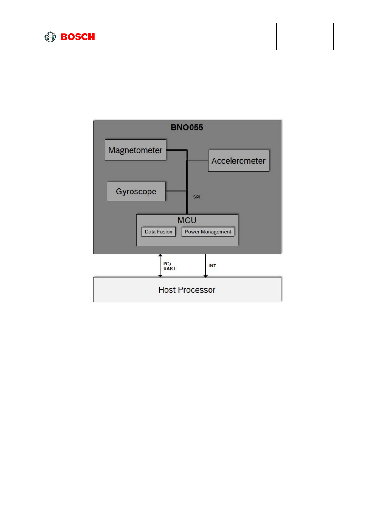
3.1 Architecture
The following figure shows the basic building blocks of the BNO055 device.
Figure 1: system architecture
3.2 Power management
The BNO055 has two distinct power supply pins:
• VDD is the main power supply for the internal sensors
• V
For the switching sequence of power supply VDD and VDDIO it is mandatory that VDD is powered
on and driven to the specified level before or at the same time as VDDIO is powered ON.
Otherwise there are no limitations on the voltage levels of both pins relative to each other, as
long as they are used within the specified operating range.
The sensor features a power-on reset (POR), initializing the register map with the default
values and starting in CONFIG mode. The POR is executed at every power on and can also
be triggered either by applying a low signal to the nRESET pin for at least 20ns or by setting
the RST_SYS bit in the SYS_TRIGGER register.
The BNO055 can be configured to run in one of the following power modes: normal mode,
low power mode, and suspend mode. These power modes are described in more detail in
section Power Modes
is a separate power supply pin used for the supply of the µC and the digital interfaces
DDIO
BST-BNO055-DS000-14 | Revision 1.4 | June 2016 Bosch Sensortec
© Bosch Sensortec GmbH reserves all rights even in the event of industrial property rights. We reserve all rights of disposal su ch as copying and passing on
to third parties. BOSCH and the symbol are registered trademarks of Robert Bosch GmbH, Germany.
Note: Specifications within this document are subject to change without notice.
Page 19

BNO055
Data sheet
Page 19
Parameter
Value
[Reg Addr]: Reg Value
Power Mode
Normal Mode
[PWR_MODE]: xxxxxx00b
Low Power Mode
[PWR_MODE]: xxxxxx01b
Suspend Mode
[PWR_MODE]: xxxxxx10b
Description
Parameter
Value
Reg Value
Restriction
Entering to
sleep:
NO Motion
Interrupt
Detection
Type
No Motion
[ACC_NM_SET] : xxxxxxx1b
n/a
Detection Axis
[ACC_INT_Settings] : bit4-bit2
Shares common
bit with Any Motion
interrupt axis
selection
Params
Duration
[ACC_NM_SET] : bit6-bit1
n/a
Threshold
[ACC_NM_THRE] : bit7-bit0
n/a
Description
Parameter
Value
Reg Value
Waking up: Any
Motion Interrupt
Detection Type
Detection Axis
[ACC_INT_Settings] : bit4-bit2
Params
Duration
[ACC_INT_Settings] : bit1-bit0
Threshold
[ACC_AM_THRES] : bit7-bit0
Power Modes
The BNO055 support three different power modes: Normal mode, Low Power Mode, and
Suspend mode.
The power mode can be selected by writing to the PWR_MODE register as defined in the
table below. As default at start-up the BNO055 will run in Normal mode.
Table 3-1: power modes selection
3.2.1 Normal Mode
In normal mode all sensors required for the selected operating mode (see section 3.3) are
always switched ON. The register map and the internal peripherals of the MCU are always
operative in this mode.
3.2.2 Low Power Mode
If no activity (i.e. no motion) is detected for a configurable duration (default 5 seconds), the
BNO055 enters the low power mode. In this mode only the accelerometer is active. Once
motion is detected (i.e. the accelerometer signals an any-motion interrupt), the system is
woken up and normal mode is entered. The following settings are possible.
Table 3-2: Low power modes - Interrupts
Additionally, the interrupt pins can also be configured to provide HW interrupt to the host.
The BNO055 is by default configured to have optimum values for entering into sleep and
waking up. To restore these values, trigger system reset by setting RST_SYS bit in
SYS_TRIGGER register.
There are some limitations to achieve the low power mode performance:
Only No and Any motion interrupts are applicable and High-G and slow motion
interrupts are not applicable in low power mode.
Low power mode is not applicable where accelerometer is not employed.
BST-BNO055-DS000-14 | Revision 1.4 | June 2016 Bosch Sensortec
© Bosch Sensortec GmbH reserves all rights even in the event of industrial property rights. We reserve all rights of disposal su ch as copying and passing on
to third parties. BOSCH and the symbol are registered trademarks of Robert Bosch GmbH, Germany.
Note: Specifications within this document are subject to change without notice.
Page 20

BNO055
Data sheet
Page 20
Operating Mode
Available sensor signals
Fusion Data
Accel
Mag
Gyro
Relative
orientation
Absolute
orientation
CONFIGMODE
- - - - -
Non
-fusion
modes
ACCONLY
X - - - -
MAGONLY
- X - - -
GYROONLY
- - X - -
ACCMAG
X X - - -
ACCGYRO
X - X - -
MAGGYRO
- X X - AMG
X X X - -
Fusion modes
IMU
X - X X -
COMPASS
X X - - X
M4G
X X X -
NDOF_FMC_OFF
X X X - X
NDOF
X X X - X
3.2.3 Suspend Mode
In suspend mode the system is paused and all the sensors and the microcontroller are put
into sleep mode. No values in the register map will be updated in this mode. To exit from
suspend mode the mode should be changed by writing to the PWR_MODE register (see
Table 3-1).
3.3 Operation Modes
The BNO055 provides a variety of output signals, which can be chosen by selecting the
appropriate operation mode. The table below lists the different modes and the available
sensor signals.
Table 3-3: Operating modes overview
The default operation mode after power-on is CONFIGMODE.
When the user changes to another operation mode, the sensors which are required in that
particular sensor mode are powered, while the sensors whose signals are not required are
set to suspend mode.
BST-BNO055-DS000-14 | Revision 1.4 | June 2016 Bosch Sensortec
© Bosch Sensortec GmbH reserves all rights even in the event of industrial property rights. We reserve all rights of disposal su ch as copying and passing on
to third parties. BOSCH and the symbol are registered trademarks of Robert Bosch GmbH, Germany.
Note: Specifications within this document are subject to change without notice.
Page 21

BNO055
Data sheet
Page 21
Sensor
Range
Bandwidth
Accelerometer
4G
62.5 Hz
Magnetometer
NA
10 Hz
Gyroscope
2000 dps
32 Hz
Parameter
Value
[Reg Addr]: Reg Value
CONFIG MODE
CONFIGMODE
[OPR_MODE]: xxxx0000b
Non-Fusion
Mode
ACCONLY
[OPR_MODE]: xxxx0001b
MAGONLY
[OPR_MODE]: xxxx0010b
GYROONLY
[OPR_MODE]: xxxx0011b
ACCMAG
[OPR_MODE]: xxxx0100b
ACCGYRO
[OPR_MODE]: xxxx0101b
MAGGYRO
[OPR_MODE]: xxxx0110b
AMG
[OPR_MODE]: xxxx0111b
Fusion Mode
IMU
[OPR_MODE]: xxxx1000b
COMPASS
[OPR_MODE]: xxxx1001b
M4G
[OPR_MODE]: xxxx1010b
NDOF_FMC_OFF
[OPR_MODE]: xxxx1011b
NDOF
[OPR_MODE]: xxxx1100b
From
To
Switching time
CONFIGMODE
Any operation mode
7ms
Any operation mode
CONFIGMODE
19ms
The BNO055 sets the following default settings for the sensors. The user can overwrite these
settings in the register map when in CONFIGMODE.
Table 3-4: Default sensor settings
In any mode, the sensor data are available in the data register based on the unit selected.
The axis of the data is configured based on the axis-remap register configuration.
The operating mode can be selected by writing to the OPR_MODE register, possible register
values and the corresponding operating modes are shown in the table below.
Table 3-5: operating modes selection
Table 3-6 below shows the time required to switch between CONFIGMODE and the other
operating modes.
Table 3-6: Operating mode switching time
BST-BNO055-DS000-14 | Revision 1.4 | June 2016 Bosch Sensortec
© Bosch Sensortec GmbH reserves all rights even in the event of industrial property rights. We reserve all rights of disposal su ch as copying and passing on
to third parties. BOSCH and the symbol are registered trademarks of Robert Bosch GmbH, Germany.
Note: Specifications within this document are subject to change without notice.
Page 22

BNO055
Data sheet
Page 22
3.3.1 Config Mode
This mode is used to configure BNO, wherein all output data is reset to zero and sensor
fusion is halted. This is the only mode in which all the writable register map entries can be
changed. (Exceptions from this rule are the interrupt registers (INT and INT_MSK) and the
operation mode register (OPR_MODE), which can be modified in any operation mode.)
As being said, this mode is the default operation mode after power-on or RESET. Any other
mode must be chosen to be able to read any sensor data.
3.3.2 Non-Fusion Modes
3.3.2.1 ACCONLY
If the application requires only raw accelerometer data, this mode can be chosen. In this
mode the other sensors (magnetometer, gyro) are suspended to lower the power
consumption. In this mode, the BNO055 behaves like a stand-alone acceleration sensor.
3.3.2.1 MAGONLY
In MAGONLY mode, the BNO055 behaves like a stand-alone magnetometer, with
acceleration sensor and gyroscope being suspended.
3.3.2.2 GYROONLY
In GYROONLY mode, the BNO055 behaves like a stand-alone gyroscope, with acceleration
sensor and magnetometer being suspended.
3.3.2.3 ACCMAG
Both accelerometer and magnetometer are switched on, the user can read the data from
these two sensors.
3.3.2.4 ACCGYRO
Both accelerometer and gyroscope are switched on; the user can read the data from these
two sensors.
3.3.2.5 MAGGYRO
Both magnetometer and gyroscope are switched on, the user can read the data from these
two sensors.
3.3.2.6 AMG (ACC-MAG-GYRO)
All three sensors accelerometer, magnetometer and gyroscope are switched on.
3.3.3 Fusion modes
Sensor fusion modes are meant to calculate measures describing the orientation of the
device in space. It can be distinguished between non-absolute or relative orientation and
absolute orientation. Absolute orientation means orientation of the sensor with respect to the
earth and its magnetic field. In other words, absolute orientation sensor fusion modes
calculate the direction of the magnetic north pole.
In non-absolute or relative orientation modes, the heading of the sensor can vary depending
on how the sensor is placed initially.
All fusion modes provide the heading of the sensor as quaternion data or in Euler angles
(roll, pitch and yaw angle). The acceleration sensor is both exposed to the gravity force and
to accelerations applied to the sensor due to movement. In fusion modes it is possible to
separate the two acceleration sources, and thus the sensor fusion data provides separately
linear acceleration (i.e. acceleration that is applied due to movement) and the gravity vector.
BST-BNO055-DS000-14 | Revision 1.4 | June 2016 Bosch Sensortec
© Bosch Sensortec GmbH reserves all rights even in the event of industrial property rights. We reserve all rights of disposal su ch as copying and passing on
to third parties. BOSCH and the symbol are registered trademarks of Robert Bosch GmbH, Germany.
Note: Specifications within this document are subject to change without notice.
Page 23

BNO055
Data sheet
Page 23
3.3.3.1 IMU (Inertial Measurement Unit)
In the IMU mode the relative orientation of the BNO055 in space is calculated from the
accelerometer and gyroscope data. The calculation is fast (i.e. high output data rate).
3.3.3.2 COMPASS
The COMPASS mode is intended to measure the magnetic earth field and calculate the
geographic direction.
The earth magnetic field is a vector with the horizontal components x,y and the vertical z
component. It depends on the position on the globe and natural iron occurrence. For heading
calculation (direction of compass pointer) only the horizontal components x and y are used.
Therefore the vector components of the earth magnetic field must be transformed in the
horizontal plane, which requires the knowledge of the direction of the gravity vector. To
summarize, the heading can only be calculated when considering gravity and magnetic field
at the same time.
However, the measurement accuracy depends on the stability of the surrounding magnetic
field. Furthermore, since the earth magnetic field is usually much smaller than the magnetic
fields that occur around and inside electronic devices, the compass mode requires calibration
(see chapter 3.10)
3.3.3.3 M4G (Magnet for Gyroscope)
The M4G mode is similar to the IMU mode, but instead of using the gyroscope signal to
detect rotation, the changing orientation of the magnetometer in the magnetic field is used.
Since the magnetometer has much lower power consumption than the gyroscope, this mode
is less power consuming in comparison to the IMU mode. There are no drift effects in this
mode which are inherent to the gyroscope.
However, as for compass mode, the measurement accuracy depends on the stability of the
surrounding magnetic field.
For this mode no magnetometer calibration is required and also not available.
3.3.3.4 NDOF_FMC_OFF
This fusion mode is same as NDOF mode, but with the Fast Magnetometer Calibration
turned ‘OFF’.
3.3.3.5 NDOF
This is a fusion mode with 9 degrees of freedom where the fused absolute orientation data is
calculated from accelerometer, gyroscope and the magnetometer. The advantages of
combining all three sensors are a fast calculation, resulting in high output data rate, and high
robustness from magnetic field distortions. In this mode the Fast Magnetometer calibration is
turned ON and thereby resulting in quick calibration of the magnetometer and higher output
data accuracy. The current consumption is slightly higher in comparison to the
NDOF_FMC_OFF fusion mode.
BST-BNO055-DS000-14 | Revision 1.4 | June 2016 Bosch Sensortec
© Bosch Sensortec GmbH reserves all rights even in the event of industrial property rights. We reserve all rights of disposal su ch as copying and passing on
to third parties. BOSCH and the symbol are registered trademarks of Robert Bosch GmbH, Germany.
Note: Specifications within this document are subject to change without notice.
Page 24

BNO055
Data sheet
Page 24
Bit 7
Bit 6
Bit 5
Bit 4
Bit 3
Bit 2
Bit 1
Bit 0
Reserved
Remapped Z axis value
Remapped Y axis
value
Remapped X axis
value
Value
Axis Representation
00
X - Axis
01
Y - Axis
10
Z- Axis
11
Invalid
Bit 7
Bit 6
Bit 5
Bit 4
Bit 3
Bit 2
Bit 1
Bit 0
Reserved
Remapped
X axis sign
Remapped
Y axis sign
Remapped
Z axis sign
Value
Sign
0
Positive
1
Negative
Z; Ωz; z
X; Ωx; x
Y; Ωy; y
Accel; Gyro; Magnet
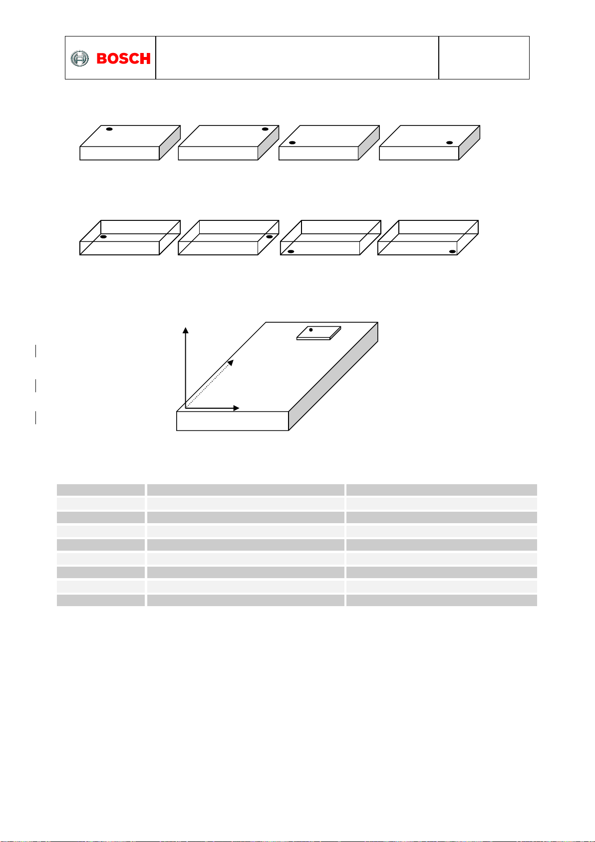
3.4 Axis remap
The device mounting position should not limit the data output of the BNO055 device. The
axis of the device can be re-configured to the new reference axis.
Axis configuration byte: Register Address: AXIS_MAP_CONFIG
There are two bits are used to configure the axis remap which will define in the following
way,
Also, when user try to configure the same axis to two or more then BNO055 will take this as
invalid condition and previous configuration will be restored in the register map. The default
value is: X Axis = X, Y Axis = Y and Z Axis = Z (AXIS_REMAP_CONFIG = 0x24).
Axis sign configuration byte: Register Address: AXIS_MAP_SIGN
The default value is 0x00.
The default values correspond to the following coordinate system
BST-BNO055-DS000-14 | Revision 1.4 | June 2016 Bosch Sensortec
© Bosch Sensortec GmbH reserves all rights even in the event of industrial property rights. We reserve all rights of disposal su ch as copying and passing on
to third parties. BOSCH and the symbol are registered trademarks of Robert Bosch GmbH, Germany.
Note: Specifications within this document are subject to change without notice.
Page 25
BNO055
Data sheet
Page 25
Placement
AXIS_REMAP_CONFIG
AXIS_REMAP_SIGN
P0
0x21
0x04
P1 (default)
0x24
0x00
P2
0x24
0x06
P3
0x21
0x02
P4
0x24
0x03
P5
0x21
0x01
P6
0x21
0x07
P7
0x24
0x05
TOP VIEW
BOTTOM VIEW
ZYX
P0
P1
P2
P3
P4
P5
P6
P7
P0
Some example placement for axis vs. register settings:
For the above described placements, following would be the axis configuration parameters.
BST-BNO055-DS000-14 | Revision 1.4 | June 2016 Bosch Sensortec
© Bosch Sensortec GmbH reserves all rights even in the event of industrial property rights. We reserve all rights of disposal su ch as copying and passing on
to third parties. BOSCH and the symbol are registered trademarks of Robert Bosch GmbH, Germany.
Note: Specifications within this document are subject to change without notice.
Page 26

BNO055
Data sheet
Page 26
Sensors
Parameters
Value
Accelerometer
Power Mode
NORMAL
Range
+/- 4g
Bandwidth
62.5Hz
Resolution
14 bits
Gyroscope
Power Mode
NORMAL
Range
2000 °/s
Bandwidth
32Hz
Resolution
16 bits
Magnetometer
Power Mode
FORCED
ODR
20Hz
XY Repetition
15
Z Repetition
16
Resolution x/y/z
13/13/15 bits
3.5 Sensor Configuration
The fusion outputs of the BNO055 are tightly linked with the sensor configuration settings.
Due to this fact, the sensor configuration is limited when BNO055 is configured to run in any
of the fusion operating mode. In any of the non-fusion modes the configuration settings can
be updated by writing to the configuration registers as defined in the following sections.
3.5.1 Default sensor configuration
At power-on the sensors are configured with the default settings as defined in Table 3-8
below.
Table 3-7: Default sensor configuration at power-on
BST-BNO055-DS000-14 | Revision 1.4 | June 2016 Bosch Sensortec
© Bosch Sensortec GmbH reserves all rights even in the event of industrial property rights. We reserve all rights of disposal su ch as copying and passing on
to third parties. BOSCH and the symbol are registered trademarks of Robert Bosch GmbH, Germany.
Note: Specifications within this document are subject to change without notice.
Page 27

BNO055
Data sheet
Page 27
Parameter
Values
[Reg Addr]: Reg Value
Restrictions
G Range
2G
[ACC_Config]: xxxxxx00b
Auto controlled in fusion
mode
4G
[ACC_Config]: xxxxxx01b
8G
[ACC_Config]: xxxxxx10b
16G
[ACC_Config]: xxxxxx11b
Bandwidth
7.81Hz
[ACC_Config]: xxx000xxb
15.63Hz
[ACC_Config]: xxx001xxb
31.25Hz
[ACC_Config]: xxx010xxb
62.5Hz
[ACC_Config]: xxx011xxb
125Hz
[ACC_Config]: xxx100xxb
250Hz
[ACC_Config]: xxx101xxb
500Hz
[ACC_Config]: xxx110xxb
1000Hz
[ACC_Config]: xxx111xxb
Operation Mode
Normal
[ACC_Config]: 000xxxxxb
Suspend
[ACC_Config]: 001xxxxxb
Low Power 1
[ACC_Config]: 010xxxxxb
Standby
[ACC_Config]: 011xxxxxb
Low Power 2
[ACC_Config]: 100xxxxxb
Deep Suspend
[ACC_Config]: 101xxxxxb
3.5.2 Accelerometer configuration
The fusion outputs of the BNO055 are tightly linked with the accelerometer sensor settings.
Therefore the configuration possibilities are restricted when running in any of the fusion
operating modes. The accelerometer configuration can be changed by writing to the
ACC_Config register, Table below shows different Accelerometer configurations
Table 3-8: Accelerometer configurations
The accelerometer sensor operation mode is not configurable by user when BNO power
mode is configured as low power mode. BNO rewrites the user configured value to Normal
mode when switching from config mode to any BNO operation mode. This used to achieve
the BNO low power mode performance.
BST-BNO055-DS000-14 | Revision 1.4 | June 2016 Bosch Sensortec
© Bosch Sensortec GmbH reserves all rights even in the event of industrial property rights. We reserve all rights of disposal su ch as copying and passing on
to third parties. BOSCH and the symbol are registered trademarks of Robert Bosch GmbH, Germany.
Note: Specifications within this document are subject to change without notice.
Page 28

BNO055
Data sheet
Page 28
Parameter
Values
[Reg Addr]: Register value
Restrictions
Range
2000 dps
[GYR_Config_0]: xxxxx000b
Auto controlled in fusion mode
1000 dps
[GYR_Config_0]: xxxxx001b
500dps
[GYR_Config_0]: xxxxx010b
250 dps
[GYR_Config_0]: xxxxx011b
125 dps
[GYR_Config_0]: xxxxx100b
Bandwidth
523Hz
[GYR_Config_0]: xx000xxxb
230Hz
[GYR_Config_0]: xx001xxxb
116Hz
[GYR_Config_0]: xx010xxxb
47Hz
[GYR_Config_0]: xx011xxxb
23Hz
[GYR_Config_0]: xx100xxxb
12Hz
[GYR_Config_0]: xx101xxxb
64Hz
[GYR_Config_0]: xx110xxxb
32Hz
[GYR_Config_0]: xx111xxxb
Operation Mode
Normal
[GYR_Config_1]: xxxxx000b
Fast Power up
[GYR_Config_1]: xxxxx001b
Deep Suspend
[GYR_Config_1]: xxxxx010b
Suspend
[GYR_Config_1]: xxxxx011b
Advanced
Powersave
[GYR_Config_1]: xxxxx100b
3.5.3 Gyroscope configuration
The fusion outputs of the BNO055 are tightly linked with the angular rate sensor settings.
Therefore the configuration possibilities are restricted when running in any of the fusion
operating modes. The gyroscope configuration can be changed by writing to the GYR_Config
register, Table below shows different Gyroscope configurations
Table 3-9: Gyroscope configurations
BST-BNO055-DS000-14 | Revision 1.4 | June 2016 Bosch Sensortec
© Bosch Sensortec GmbH reserves all rights even in the event of industrial property rights. We reserve all rights of disposal su ch as copying and passing on
to third parties. BOSCH and the symbol are registered trademarks of Robert Bosch GmbH, Germany.
Note: Specifications within this document are subject to change without notice.
Page 29

BNO055
Data sheet
Page 29
Parameter
Values
[Reg Addr]: Register
value
Restrictions
Data output rate
2Hz
[MAG_Config]: xxxxx000b
Auto controlled in fusion mode
6Hz
[MAG_Config]: xxxxx001b
8Hz
[MAG_Config]: xxxxx010b
10Hz
[MAG_Config]: xxxxx011b
15Hz
[MAG_Config]: xxxxx100b
20Hz
[MAG_Config]: xxxxx101b
25Hz
[MAG_Config]: xxxxx110b
30Hz
[MAG_Config]: xxxxx111b
Operation Mode
Low Power
[MAG_Config]: xxx00xxxb
Regular
[MAG_Config]: xxx01xxxb
Enhanced
Regular
[MAG_Config]: xxx10xxxb
High Accuracy
[MAG_Config]: xxx11xxxb
Power Mode
Normal
[MAG_Config]: x00xxxxxb
Sleep
[MAG_Config]: x01xxxxxb
Suspend
[MAG_Config]: x10xxxxxb
Force Mode
[MAG_Config]: x11xxxxxb
3.5.4 Magnetometer configuration
The fusion outputs of the BNO055 are tightly linked with the magnetometer sensor settings.
Therefore the configuration possibilities are restricted when running in any of the fusion
operating modes. The magnetometer configuration can be changed by writing to the
MAG_Config register, Table below shows different Magnetometer configurations.
Table 3-10: Magnetometer configurations
BST-BNO055-DS000-14 | Revision 1.4 | June 2016 Bosch Sensortec
© Bosch Sensortec GmbH reserves all rights even in the event of industrial property rights. We reserve all rights of disposal su ch as copying and passing on
to third parties. BOSCH and the symbol are registered trademarks of Robert Bosch GmbH, Germany.
Note: Specifications within this document are subject to change without notice.
Page 30

BNO055
Data sheet
Page 30
Data
Units
[Reg Addr]: Register Value
Acceleration, Linear
Acceleration, Gravity
vector
m/s2
[UNIT_SEL] : xxxxxxx0b
mg
[UNIT_SEL] : xxxxxxx1b
Magnetic Field Strength
Micro Tesla
NA
Angular Rate
Dps
[UNIT_SEL] : xxxxxx0xb
Rps
[UNIT_SEL] : xxxxxx1xb
Euler Angles
Degrees
[UNIT_SEL] : xxxxx0xxb
Radians
[UNIT_SEL] : xxxxx1xxb
Quaternion
Quaternion
units
NA
Temperature
°C
[UNIT_SEL] : xxx0xxxxb
°F
[UNIT_SEL] : xxx1xxxxb
Parameter
Values
[Reg Addr]: Register value
Fusion data output
format
Windows
[UNIT_SEL]: 0xxxxxxxb
Android
[UNIT_SEL]: 1xxxxxxxb
Rotation angle
Range (Android format)
Range (Windows format)
Pitch
+180° to -180° (turning
clockwise decreases values)
-180° to +180° (turning clockwise increases values)
Roll
-90° to +90° (increasing with increasing inclination)
Heading / Yaw
0° to 360° (turning clockwise increases values)
3.6 Output data
Depending on the selected operating mode the device will output either un-calibrated sensor
data (in non-fusion mode) or calibrated / fused data (in fusion mode), this section describes
the output data for each modes.
3.6.1 Unit selection
The measurement units for the various data outputs (regardless of operation mode) can be
configured by writing to the UNIT_SEL register as described in Table 3-9.
Table 3-11: unit selection
3.6.2 Data output format
The data output format can be selected by writing to the UNIT_SEL register, this allows user
to switch between the orientation definition described by Windows and Android operating
systems.
Table 3-12: Fusion data output format
The output data format is based on the following convention regarding the rotation angles for
roll, pitch and heading / yaw (compare also section 3.4):
Table 3-13: Rotation angle conventions
BST-BNO055-DS000-14 | Revision 1.4 | June 2016 Bosch Sensortec
© Bosch Sensortec GmbH reserves all rights even in the event of industrial property rights. We reserve all rights of disposal su ch as copying and passing on
to third parties. BOSCH and the symbol are registered trademarks of Robert Bosch GmbH, Germany.
Note: Specifications within this document are subject to change without notice.
Page 31

BNO055
Data sheet
Page 31
BNO055 Operating
Mode
Data input rate
Algo
calling
rate
Data output rate
Accel
Mag
Gyro
Accel
Mag
Gyro
Fusion
data
IMU
100Hz
NA
100Hz
100Hz
100Hz
NA
100Hz
100Hz
COMPASS
20Hz
20Hz
NA
20Hz
20Hz
20Hz
NA
20Hz
M4G
50Hz
50Hz
NA
50Hz
50Hz
50Hz
NA
50Hz
NDOF_FMC_OFF
100Hz
20Hz
100Hz
100Hz
100Hz
20Hz
100Hz
100Hz
NDOF
100Hz
20Hz
100Hz
100Hz
100Hz
20Hz
100Hz
100Hz
Reg Name
Default Reg Value (Bit 0 – Bit 7)
ACC_OFFSET_X_LSB
0x00
ACC_OFFSET_X_MSB
0x00
ACC_OFFSET_Y_LSB
0x00
ACC_OFFSET_Y_MSB
0x00
ACC_OFFSET_Z_LSB
0x00
ACC_OFFSET_Z_MSB
0x00
Accelerometer G-range
Maximum Offset range in mg
2G
+/- 2000
4G
+/- 4000
8G
+/- 8000
16G
+/- 16000
Unit
Representation
m/s2
1 m/s2 = 100 LSB
mg
1 mg = 1 LSB
3.6.3 Fusion Output data rates
Table 3-14: Fusion output data rates
3.6.4 Sensor calibration data
The following section describes the register holding the calibration data of the sensors (see
chapter 3.11). The offset and radius data can be read from these registers and stored in the
host system, which could be later used to get the correct orientation data after ‘Power on
Reset’ of the sensor.
3.6.4.1 Accelerometer offset
The accelerometer offset can be configured in the following registers, shown in the table
below. There are 6 bytes required to configure the accelerometer offset (2 bytes for each of
the 3 axis X, Y and Z). Configuration will take place only when the user writes the last byte
(i.e., ACC_OFFSET_Z_MSB).
Table 3-15: Accelerometer Default-Reg settings
The range of the offsets varies based on the G-range of accelerometer sensor.
Table 3-16: Accelerometer G-range settings
Table 3-17: Accelerometer Unit settings
BST-BNO055-DS000-14 | Revision 1.4 | June 2016 Bosch Sensortec
© Bosch Sensortec GmbH reserves all rights even in the event of industrial property rights. We reserve all rights of disposal su ch as copying and passing on
to third parties. BOSCH and the symbol are registered trademarks of Robert Bosch GmbH, Germany.
Note: Specifications within this document are subject to change without notice.
Page 32

BNO055
Data sheet
Page 32
Reg Name
Default Reg Value (Bit 0 – Bit 7)
MAG_OFFSET_X_LSB
0x00
MAG_OFFSET_X_MSB
0x00
MAG_OFFSET_Y_LSB
0x00
MAG_OFFSET_Y_MSB
0x00
MAG_OFFSET_Z_LSB
0x00
MAG_OFFSET_Z_MSB
0x00
Unit
Representation
µT
1 µT = 16 LSB
Reg Name
Default Reg Value (Bit 0 – Bit 7)
GYR_OFFSET_X_LSB
0x00
GYR_OFFSET_X_MSB
0x00
GYR_OFFSET_Y_LSB
0x00
GYR_OFFSET_Y_MSB
0x00
GYR_OFFSET_Z_LSB
0x00
GYR_OFFSET_Z_MSB
0x00
3.6.4.2 Magnetometer offset
The magnetometer offset can be configured in the following registers,
Table 3-18: Magnetometer Default-Reg settings
There are 6 bytes required to configure the magnetometer offset (bytes (2 bytes for each of
the 3 axis X, Y and Z). Configuration will take place only when the user writes the last byte
(i.e., MAG_OFFSET_Z_MSB). Therefore the last byte must be written whenever the user
wants to changes the configuration. The range of the magnetometer offset is +/-6400 in LSB.
Table 3-19: Magnetometer Unit settings
3.6.4.3 Gyroscope offset
The gyroscope offset can be configured in the following registers, shown in the table below
Table 3-20: Gyroscope Default Reg-settings
There are 6 bytes required to configure the gyroscope offset (bytes (2 bytes for each of the 3
axis X, Y and Z). Configuration will take place only when the user writes the last byte (i.e.,
GYR_OFFSET_Z_MSB). Therefore the last byte must be written whenever the user wants to
changes the configuration. The range of the offset varies based on the dps-range of
gyroscope sensor.
BST-BNO055-DS000-14 | Revision 1.4 | June 2016 Bosch Sensortec
© Bosch Sensortec GmbH reserves all rights even in the event of industrial property rights. We reserve all rights of disposal su ch as copying and passing on
to third parties. BOSCH and the symbol are registered trademarks of Robert Bosch GmbH, Germany.
Note: Specifications within this document are subject to change without notice.
Page 33

BNO055
Data sheet
Page 33
Gyroscope dps range
Maximum Offset range in LSB
2000
+/- 32000
1000
+/- 16000
500
+/- 8000
250
+/- 4000
125
+/- 2000
Unit
Representation
Dps
1 Dps = 16 LSB
Rps
1 Rps = 900 LSB
Reg Name
Default Reg Value (Bit 0 – Bit 7)
ACC_RADIUS_LSB
0x00
ACC_RADIUS_MSB
0x00
MAG_RADIUS_LSB
0x00
MAG_RADIUS_MSB
0x00
Radius for sensor
Maximum Range
Accelerometer
+/- 1000 LSB
Magnetometer
+/- 960 LSB
Table 3-21: Gyroscope range settings
Table 3-22: Gyroscope unit settings
3.6.4.4 Radius
The radius of accelerometer, magnetometer and gyroscope can be configured in the
following registers,
Table 3-23: Radius Default-Reg settings
There are 4 bytes (2 bytes for each accelerometer and magnetometer) to configure the
radius. Configuration will take place only when user writes to the last byte (i.e.,
ACC_RADIUS_MSB and MAG_RADIUS_MSB). Therefore the last byte must be written
whenever the user wants to changes the configuration. The range of the radius for
accelerometer is +/-1000, magnetometer is +/-960 and Gyroscope is NA.
Table 3-24: Radius range settings
3.6.5 Output data registers
3.6.5.1 Acceleration data
In non-fusion mode uncompensated acceleration data for each axis X/Y/Z, can be read from
the appropriate ACC_DATA_<axis>_LSB and ACC_DATA_<axis>_MSB registers.
In fusion mode the fusion algorithm output offset compensated acceleration data for each
axis X/Y/Z, the output data can be read from the appropriate ACC_DATA_<axis>_LSB and
ACC_DATA_<axis>_MSB registers. Refer table below for information regarding the data
types for the acceleration data.
BST-BNO055-DS000-14 | Revision 1.4 | June 2016 Bosch Sensortec
© Bosch Sensortec GmbH reserves all rights even in the event of industrial property rights. We reserve all rights of disposal su ch as copying and passing on
to third parties. BOSCH and the symbol are registered trademarks of Robert Bosch GmbH, Germany.
Note: Specifications within this document are subject to change without notice.
Page 34

BNO055
Data sheet
Page 34
Parameter
Data type
bytes
Accel_Data_X
signed
2
Accel_Data_Y
signed
2
Accel_Data_Z
signed
2
Parameter
Data type
bytes
Mag_Data_X
signed
2
Mag_Data_Y
signed
2
Mag_Data_Z
signed
2
Parameter
Data type
bytes
Gyr_Data_X
signed
2
Gyr_Data_Y
signed
2
Gyr_Data_Z
signed
2
Table 3-25: Acceleration data
3.6.5.2 Magnetic Field Strength
In non-fusion mode uncompensated field strength data for each axis X/Y/Z, can be read from
the appropriate MAG_DATA_<axis>_LSB and MAG_DATA_<axis>_MSB registers.
In fusion mode the fusion algorithm output offset compensated magnetic field strength data
for each axis X/Y/Z, the output data can be read from the appropriate
MAG_DATA_<axis>_LSB and MAG_DATA_<axis>_MSB registers. Refer table below for
information regarding the data types for the magnetic field strength.
Table 3-26: Magnetic field strength data
3.6.5.3 Angular Velocity
In non-fusion mode uncompensated angular velocity (yaw rate) data for each axis X/Y/Z, can
be read from the appropriate GYR_DATA_<axis>_LSB and GYR_DATA_<axis>_MSB
registers.
In fusion mode the fusion algorithm output offset compensated angular velocity (yaw rate)
data for each axis X/Y/Z, the output data can be read from the appropriate
GYR_DATA_<axis>_LSB and GYR_DATA_<axis>_MSB registers. Refer table below for
information regarding the data types for the angular velocity.
Table 3-27: Yaw rate data
BST-BNO055-DS000-14 | Revision 1.4 | June 2016 Bosch Sensortec
© Bosch Sensortec GmbH reserves all rights even in the event of industrial property rights. We reserve all rights of disposal su ch as copying and passing on
to third parties. BOSCH and the symbol are registered trademarks of Robert Bosch GmbH, Germany.
Note: Specifications within this document are subject to change without notice.
Page 35

BNO055
Data sheet
Page 35
Parameter
Data type
bytes
EUL_Heading
Signed
2
EUL_Roll
Signed
2
EUL_Pitch
Signed
2
Unit
Representation
Degrees
1 degree = 16 LSB
Radians
1 radian = 900 LSB
Parameter
Data type
bytes
QUA_Data_w
Signed
2
QUA_Data_x
Signed
2
QUA_Data_y
Signed
2
QUA_Data_z
Signed
2
Unit
Representation
Quaternion (unit less)
1 Quaternion (unit less) = 2^14 LSB
3.6.5.4 Orientation (Euler angles)
Orientation output only available in fusion operation modes.
The fusion algorithm output offset and tilt compensated orientation data in Euler angles
format for each DOF Heading/Roll/Pitch, the output data can be read from the appropriate
EUL<dof>_LSB and EUL_<dof>_MSB registers. Refer table below for information regarding
the data types and the unit representation for the Euler angle format.
Table 3-28: Compensated orientation data in Euler angles format
Table 3-29: Euler angle data representation
3.6.5.5 Orientation (Quaternion)
Orientation output only available in fusion operating modes.
The fusion algorithm output offset and tilt compensated orientation data in quaternion format
for each DOF w/x/y/z, the output data can be read from the appropriate
QUA_DATA_<dof>_LSB and QUA_DATA_<dof>_MSB registers. Refer table below for
information regarding the data types and the unit representation for the Orientation output.
Table 3-30: Compensated orientation data in quaternion format
Table 3-31: Quaternion data representation
BST-BNO055-DS000-14 | Revision 1.4 | June 2016 Bosch Sensortec
© Bosch Sensortec GmbH reserves all rights even in the event of industrial property rights. We reserve all rights of disposal su ch as copying and passing on
to third parties. BOSCH and the symbol are registered trademarks of Robert Bosch GmbH, Germany.
Note: Specifications within this document are subject to change without notice.
Page 36

BNO055
Data sheet
Page 36
Parameter
Data type
bytes
LIA_Data_X
signed
2
LIA_Data_Y
signed
2
LIA_Data_Z
signed
2
Unit
Representation
m/s2
1 m/s2 = 100 LSB
mg
1 mg = 1 LSB
Parameter
Data type
bytes
GRV_Data_X
signed
2
GRV_Data_Y
signed
2
GRV_Data_Z
signed
2
Unit
Representation
m/s2
1 m/s2 = 100 LSB
mg
1 mg = 1 LSB
3.6.5.6 Linear Acceleration
Linear acceleration output only available in fusion operating modes.
The fusion algorithm output linear acceleration data for each axis x/y/z, the output data can
be read from the appropriate LIA_DATA_<axis>_LSB and LIA_DATA_<axis>_MSB registers.
Refer table below for further information regarding the data types and the unit representation
for Linear acceleration
Table 3-32: Linear Acceleration Data
Table 3-33: Linear Acceleration data representation
3.6.5.7 Gravity Vector
Gravity Vector output only available in fusion operating modes.
The fusion algorithm output gravity vector data for each axis x/y/z, the output data can be
read from the appropriate GRV_DATA_<axis>_LSB and GRV_DATA_<axis>_MSB registers.
Refer table below for further information regarding the data types and the unit representation
for the Gravity vector.
Table 3-34: Gravity Vector Data
Table 3-35: Gravity Vector data representation
BST-BNO055-DS000-14 | Revision 1.4 | June 2016 Bosch Sensortec
© Bosch Sensortec GmbH reserves all rights even in the event of industrial property rights. We reserve all rights of disposal su ch as copying and passing on
to third parties. BOSCH and the symbol are registered trademarks of Robert Bosch GmbH, Germany.
Note: Specifications within this document are subject to change without notice.
Page 37

BNO055
Data sheet
Page 37
Parameter
Data type
bytes
TEMP
signed
1
Unit
Representation
°C
1°C = 1 LSB
F
2 F = 1 LSB
Source
[Reg Addr]: Register Value
Accelerometer
[TEMP_SOURCE]: xxxxxx00b
Gyroscope
[TEMP_SOURCE]: xxxxxx01b
3.6.5.8 Temperature
The temperature output data can be read from the TEMP register. The table below describes
the output data type and data representation (depending on selected unit).
The temperature can be read from one of two sources, the temperature source can be
selected by writing to the TEMP_SOURCE register as detailed below.
Table 3-36: Temperature Data
Table 3-37: Temperature data representation
Table 3-38: Temperature Source Selection
3.7 Data register shadowing
This section describes the two methods to read sensor data from the BNO055 register map.
In the first method also called multi byte read (or burst read) the data consistency is ensured
by data register shadowing and hence the LSB and MSB of each axis are all referring to the
same instance (refer section 4.6 I2C read access)
Whereas in the single byte reads, the MSB may get updated when the data in LSB is read
and thereby resulting in data inconsistency.
So depending upon the application, the user may select the type of data read to ensure that
the correct data is being read.
BST-BNO055-DS000-14 | Revision 1.4 | June 2016 Bosch Sensortec
© Bosch Sensortec GmbH reserves all rights even in the event of industrial property rights. We reserve all rights of disposal su ch as copying and passing on
to third parties. BOSCH and the symbol are registered trademarks of Robert Bosch GmbH, Germany.
Note: Specifications within this document are subject to change without notice.
Page 38

BNO055
Data sheet
Page 38
3.8 Interrupts
3.8.1 Interrupt Pin
INT is configured as interrupt pin for signaling an interrupt to the host. The interrupt trigger is
configured as raising edge and is latched on to the INT pin. Once an interrupt occurs, the INT
pin is set to high and will remain high until it is reset by host. This can be done by setting
RST_INT in SYS_TRIGGER register.
Interrupts can be enabled by setting the corresponding bit in the interrupt enable register
(INT_EN) and disabled when it is cleared.
Interrupt Pin Masking
Interrupts can be routed to the INT pin by setting the corresponding interrupt bit in the
INT_MSK register.
Interrupt Status
Interrupt occurrences are stored in the interrupt status register (INT_STA). All bits in this
register are cleared on read.
3.8.2 Interrupt Settings
3.8.2.1 Accelerometer Slow/No Motion Interrupt
The slow-motion/no-motion interrupt engine can be configured in two modes.
Slow-motion Interrupt is triggered when the measured slope of at least one enabled axis
exceeds the programmable slope threshold for a programmable number of samples. Hence
the engine behaves similar to the any-motion interrupt, but with a different set of parameters.
In order to suppress false triggers, the interrupt is only generated (cleared) if a certain
number N of consecutive slope data points is larger (smaller) than the slope threshold given
by slo_no_mot_dur<1:0>. The number is N = slo_no_mot_dur<1:0> + 1.
In no-motion mode an interrupt is generated if the slope on all selected axes remains smaller
than a programmable threshold for a programmable delay time. Figure 11 shows the timing
diagram for the no-motion interrupt. The scaling of the threshold value is identical to that of
the slow-motion interrupt. However, in no-motion mode register slo_no_mot_dur defines the
delay time before the no-motion interrupt is triggered.
Table 3-39 lists the delay times adjustable with register slo_no_mot_dur. The timer tick
period is 1 second. Hence using short delay times can result in considerable timing
uncertainty.
If bit SM/NM is set to ‘1’ (‘0’), the no-motion/slow-motion interrupt engine is configured in the
no-motion (slow-motion) mode. Common to both modes, the engine monitors the slopes of
the axes that have been enabled with bits AM/NM_X_AXIS, AM/NM_Y_AXIS, and
AM/NM_Z_AXIS for the x-axis, y-axis and z-axis, respectively. The measured slope values
are continuously compared against the threshold value defined in register ACC_NM_THRES.
The scaling is such that 1 LSB of ACC_NM_THRES corresponds to 3.91 mg in 2g-range
(7.81 mg in 4g-range, 15.6 mg in 8g-range and 31.3 mg in 16g-range). Therefore the
maximum value is 996 mg in 2g-range (1.99g in 4g-range, 3.98g in 8g-range and 7.97g in
16g-range). The time difference between the successive acceleration samples depends on
the selected bandwidth and equates to 1/(2 * bw).
BST-BNO055-DS000-14 | Revision 1.4 | June 2016 Bosch Sensortec
© Bosch Sensortec GmbH reserves all rights even in the event of industrial property rights. We reserve all rights of disposal su ch as copying and passing on
to third parties. BOSCH and the symbol are registered trademarks of Robert Bosch GmbH, Germany.
Note: Specifications within this document are subject to change without notice.
Page 39

BNO055
Data sheet
Page 39
slo_no_mot_dur
Delay
time
slo_no_mot_dur
Delay
time
slo_no_mot_dur
Delay
Time
0
1 s
16
40 s
32
88 s
1
2 s
17
48 s
33
96 s
2
3 s
18
56 s
34
104 s
...
...
19
64 s.
...
...
14
15 s
20
72 s
62
328 s
15
16 s
21
80 s
63
336 s
Params
Value
[Reg Addr]: Register Value
Detection Type
No Motion
[ACC_NM_SET]: xxxxxxx1b
Slow Motion
[ACC_NM_SET]: xxxxxxx0b
Interrupt Parameters
Threshold
[ACC_NM_THRE]: bit7:bit0
Duration
[ACC_NM_SET]: bit6:bit1
acceleration
slo_no_mot_th
-slo_no_mot_th
slope
time
axis x, y, or z
axis x, y, or z
slo_no_mot_dur
timer
INT
slope(t0+Δt)= acc(t0+Δt) - acc(t0)
acc(t0+Δt)
acc(t0)
Table 3-39: No-motion time-out periods
Note: slo_no_mot_dur values 22 to 31 are not specified
BST-BNO055-DS000-14 | Revision 1.4 | June 2016 Bosch Sensortec
© Bosch Sensortec GmbH reserves all rights even in the event of industrial property rights. We reserve all rights of disposal su ch as copying and passing on
to third parties. BOSCH and the symbol are registered trademarks of Robert Bosch GmbH, Germany.
Note: Specifications within this document are subject to change without notice.
Table 3-40: Timing of No-motion interrupt
Page 40

BNO055
Data sheet
Page 40
slope_th
INT
slope
acceleration
acc(t0)
acc(t0−1/(2*bw))
slope(t0)=acc(t0)−acc(t0−1/(2*bw))
time
time
time
slope_dur
slope_dur
Axis selection
X-axis
[ACC_INT_Settings]: xxxxx1xxb
Y-axis
[ACC_INT_Settings]: xxxx1xxxb
Z-axis
[ACC_INT_Settings]: xxx1xxxxb
3.8.2.2 Accelerometer Any Motion Interrupt
The any-motion interrupt uses the slope between successive acceleration signals to detect
changes in motion. An interrupt is generated when the slope (absolute value of acceleration
difference) exceeds a preset threshold. It is cleared as soon as the slope falls below the
threshold. The principle is made clear in Figure 2: Principle of any-motion detection.
Figure 2: Principle of any-motion detection
The threshold is defined through register ACC_AM_THRES. In terms of scaling 1 LSB of
ACC_AM_THRES corresponds to 3.91 mg in 2g-range (7.81 mg in 4g-range, 15.6 mg in 8grange and 31.3 mg in 16g-range). Therefore the maximum value is 996 mg in 2g-range
(1.99g in 4g-range, 3.98g in 8g-range and 7.97g in 16g-range).
The time difference between the successive acceleration signals depends on the selected
bandwidth and equates to 1/(2*bandwidth) (t=1/(2*bw)). In order to suppress false triggers,
the interrupt is only generated (cleared) if a certain number N of consecutive slope data
points is larger (smaller) than the slope threshold given by ACC_AM_THRES. This number is
set by the AM_DUR bits. It is N = AM_DUR + 1.
BST-BNO055-DS000-14 | Revision 1.4 | June 2016 Bosch Sensortec
© Bosch Sensortec GmbH reserves all rights even in the event of industrial property rights. We reserve all rights of disposal su ch as copying and passing on
to third parties. BOSCH and the symbol are registered trademarks of Robert Bosch GmbH, Germany.
Note: Specifications within this document are subject to change without notice.
Page 41

BNO055
Data sheet
Page 41
Example: AM_DUR = 00b, …, 11b = 1decimal, …, 4decimal.
BST-BNO055-DS000-14 | Revision 1.4 | June 2016 Bosch Sensortec
© Bosch Sensortec GmbH reserves all rights even in the event of industrial property rights. We reserve all rights of disposal su ch as copying and passing on
to third parties. BOSCH and the symbol are registered trademarks of Robert Bosch GmbH, Germany.
Note: Specifications within this document are subject to change without notice.
Page 42

BNO055
Data sheet
Page 42
Params
Value
[Reg Addr]: Register Value
Interrupt Parameters
Threshold
[ACC_AM_THRES]: bit7:bit0
Duration
[ACC_INT_Settings]: bit1:bit0
Axis selection
X-axis
[ACC_INT_Settings]: xxxxx1xxb
Y-axis
[ACC_INT_Settings]: xxxx1xxxb
Z-axis
[ACC_INT_Settings]: xxx1xxxxb
Params
Value
[Reg Addr]: Register Value
Interrupt Parameters
Threshold
[ACC_HG_THRES]: bit7 : bit0
Duration
[ACC_HG_DURATION]: bit7 : bit0
Axis selection
X-axis
[ACC_INT_Settings]: xx1xxxxxb
Y-axis
[ACC_INT_Settings]: x1xxxxxxb
Z-axis
[ACC_INT_Settings]: 1xxxxxxxb
Enabling (disabling) for each axis:
Any-motion detection can be enabled (disabled) for each axis separately by writing ´1´ (´0´)
to bits AM/NM_X_AXIS, AM/NM_Y_AXIS, AM/NM_Z_AXIS. The criteria for any-motion
detection are fulfilled and the slope interrupt is generated if the slope of any of the enabled
axes exceeds the threshold ACC_AM_THRES for [AM_DUR +1] consecutive times. As soon
as the slopes of all enabled axes fall or stay below this threshold for [AM_DUR +1]
consecutive times the interrupt is cleared unless interrupt signal is latched.
Table 3-41: Any-motion Interrupt parameters and Axis selection
3.8.2.3 Accelerometer High G Interrupt
This interrupt is based on the comparison of acceleration data against a high-g threshold for
the detection of shock or other high-acceleration events.
The high-g interrupt is enabled (disabled) per axis by writing ´1´ (´0´) to bits ACC_HIGH_G in
the INT_EN register and enabling the axis in with bits HG_X_AXIS, HG_Y_AXIS, and
HG_Z_AXIS, respectively in the ACC_INT_Settings register. The high-g threshold is set
through the ACC_HG_THRES register. The meaning of an LSB of ACC_HG_THRES
depends on the selected g-range: it corresponds to 7.81 mg in 2g-range, 15.63 mg in 4grange, 31.25 mg in 8g-range, and 62.5 mg in 16g-range (i.e. increment depends from grange setting).
The high-g interrupt is generated if the absolute value of the acceleration of at least one of
the enabled axes (´or´ relation) is higher than the threshold for at least the time defined by
the ACC_HG_DURATION register. The interrupt is reset if the absolute value of the
acceleration of all enabled axes (´and´ relation) is lower than the threshold for at least the
time defined by the ACC_HG_DURATION register. The interrupt status is stored in bit
ACC_HIGH_G in the INT_STA register. The relation between the content of
ACC_HG_DURATION and the actual delay of the interrupt generation is delay [ms] =
[ACC_HG_DURATION + 1] * 2 ms. Therefore, possible delay times range from 2 ms to 512
ms.
Table 3-42: High-G Interrupt parameters and Axis selection
BST-BNO055-DS000-14 | Revision 1.4 | June 2016 Bosch Sensortec
© Bosch Sensortec GmbH reserves all rights even in the event of industrial property rights. We reserve all rights of disposal su ch as copying and passing on
to third parties. BOSCH and the symbol are registered trademarks of Robert Bosch GmbH, Germany.
Note: Specifications within this document are subject to change without notice.
Page 43

BNO055
Data sheet
Page 43
3.8.2.4 Gyroscope High Rate Interrupt
This interrupt is based on the comparison of angular rate data against a high-rate threshold
for the detection of shock or other high-angular rate events. The principle is made clear in
Figure 3 below:
Figure 3: High rate interrupt
The high-rate interrupt is enabled (disabled) per axis by writing ´1´ (´0´) to bits
GYRO_HIGH_RATE in the INT_EN register and for each axis by writing to the HR_X_AXIS,
HR_Y_AXIS, and HR_Z_AXIS, respectively in the GYR_INT_SETTING register. The high-
rate threshold is set through the HR_<axis>_Threshold bits in the appropriate
GYR_HR_<axis>_SET register. The meaning of an LSB of HR_<axis>_Threshold depends
on the selected °/s-range: it corresponds to 62.5°/s in 2000°/s-range, 31.25°/s in 1000°/srange, 15.625°/s in 500°/s -range …). The HR_<axis>_Threshold register setting 0
corresponds to 62.26°/s in 2000°/s-range, 31.13°/s in 1000°/s-range, 15.56°/s in 500°/srange …. Therefore the maximum value is 1999.76°/s in 2000°/s-range (999.87°/s 1000°/srange, 499.93°/s in 500°/s -range …).
A hysteresis can be selected by setting the HR_<axis>_THRES_HYST bits. Analogously to
threshold, the meaning of an LSB of HR_<axis>_THRES_HYST bits is °/s-range dependent:
The HR_<axis>_THRES_HYST register setting 0 corresponds to an angular rate difference
of 62.26°/s in 2000°/s-range, 31.13°/s in 1000°/s-range, 15.56°/s in 500°/s-range …. The
meaning of an LSB of HR_<axis>_THRES_HYST depends on the selected °/s-range too: it
corresponds to 62.5°/s in 2000°/s-range, 31.25°/s in 1000°/s-range, 15.625°/s in 500°/s -
range …).
The high-rate interrupt is generated if the absolute value of the angular rate of at least one of
the enabled axes (´or´ relation) is higher than the threshold for at least the time defined by
the GYR_DUR_<axis> register. The interrupt is reset if the absolute value of the angular rate
of all enabled axes (´and´ relation) is lower than the threshold minus the hysteresis. In bit
GYR_HIGH_RATE in the INT_STA the interrupt status is stored. The relation between the
content of GYR_DUR_<axis> and the actual delay of the interrupt generation is delay [ms] =
[ GYR_DUR_<axis> + 1] * 2.5 ms. Therefore, possible delay times range from 2.5 ms to 640
ms.
BST-BNO055-DS000-14 | Revision 1.4 | June 2016 Bosch Sensortec
© Bosch Sensortec GmbH reserves all rights even in the event of industrial property rights. We reserve all rights of disposal su ch as copying and passing on
to third parties. BOSCH and the symbol are registered trademarks of Robert Bosch GmbH, Germany.
Note: Specifications within this document are subject to change without notice.
Page 44

BNO055
Data sheet
Page 44
Params
Value
[Reg Addr]: Register Value
Axis selection
X-axis
[GYR_INT_SETTING]: xxxx1xxxb
Y-axis
[GYR_INT_SETTING]: xxx1xxxxb
Z-axis
[GYR_INT_SETTING]: xx1xxxxxb
High Rate Filter
settings
Filtered
[GYR_INT_SETTING]: 0xxxxxxxb
Unfiltered
[GYR_INT_SETTING]: 1xxxxxxxb
Interrupt Settings Xaxis
Threshold
[GYR_HR_X_SET]: bit4 : bit0
Duration
[GYR_DUR_X]: bit7 : bit0
Hysteresis
[GYR_HR_X_SET]: bit6 : bit5
Interrupt Settings Yaxis
Threshold
[GYR_HR_Y_SET]: bit4 : bit0
Duration
[GYR_DUR_Y]: bit7 : bit0
Hysteresis
[GYR_HR_Y_SET]: bit6 : bit5
Interrupt Settings Xaxis
Threshold
[GYR_HR_Z_SET]: bit4 : bit0
Duration
[GYR_DUR_Z]: bit7 : bit0
Hysteresis
[GYR_HR_Z_SET]: bit6 : bit5
Table 3-43: High Rate Interrupt parameters and Axis selection
BST-BNO055-DS000-14 | Revision 1.4 | June 2016 Bosch Sensortec
© Bosch Sensortec GmbH reserves all rights even in the event of industrial property rights. We reserve all rights of disposal su ch as copying and passing on
to third parties. BOSCH and the symbol are registered trademarks of Robert Bosch GmbH, Germany.
Note: Specifications within this document are subject to change without notice.
Page 45

BNO055
Data sheet
Page 45
slope_th
INT
slope
angular rate
rate(t0)
rate(t0−1/(4*fs))
slope(t0)=gyro(t0)−gyro(t0−1/(2*bw))
time
time
time
slope_dur
slope_dur
3.8.2.5 Gyroscope Any Motion Interrupt
Any-motion (slope) detection uses the slope between successive angular rate signals to
detect changes in motion. An interrupt is generated when the slope (absolute value of
angular rate difference) exceeds a preset threshold. It is cleared as soon as the slope falls
below the threshold. The principle is made clear in Figure 4.
Figure 4: Principle of any-motion detection
The threshold is defined through register GYR_AM_THRES. In terms of scaling 1 LSB of
GYR_AM_THRES corresponds to 1 °/s in 2000°/s-range (0.5°/s in 1000°/s-range, 0.25°/s in
500°/s -range …). Therefore the maximum value is 125°/s in 2000°/s-range (62.5°/s
1000°/s-range, 31.25 in 500°/s -range …).
The time difference between the successive angular rate signals depends on the selected
update rate(fs) which is coupled to the bandwidth and equates to 1/(4*fs) (t=1/(4*fs)). For
bandwidth settings with an update rate higher than 400Hz (bandwidth =0,1,2) fs is set to
400Hz.
In order to suppress false triggers, the interrupt is only generated (cleared) if a certain
number N of consecutive slope data points is larger (smaller) than the slope threshold given
by GYR_AM_THRES. This number is set by the Slope Samples bits in the GYR_AM_SET
register. It is N = [Slope Samples + 1]*4. N is set in samples. Thus the time is scaling with the
update rate (fs).
BST-BNO055-DS000-14 | Revision 1.4 | June 2016 Bosch Sensortec
© Bosch Sensortec GmbH reserves all rights even in the event of industrial property rights. We reserve all rights of disposal su ch as copying and passing on
to third parties. BOSCH and the symbol are registered trademarks of Robert Bosch GmbH, Germany.
Note: Specifications within this document are subject to change without notice.
Page 46

BNO055
Data sheet
Page 46
Params
Value
[Reg Addr]: Register Value
Axis selection
X-axis
[GYR_INT_SETING]: xxxxxxx1b
Y-axis
[GYR_INT_SETING]: xxxxxx1xb
Z-axis
[GYR_INT_SETING]: xxxxx1xxb
Any Motion Filter
settings
Filtered
[GYR_INT_SETING]: x0xxxxxxb
Unfiltered
[GYR_INT_SETING]: x1xxxxxxb
Interrupt Settings
Threshold
[GYR_AM_THRES]: bit6 : bit0
Slope Samples
[GYR_AM_SET]: bit1 : bit0
Awake Duration
[GYR_AM_SET]: bit3 : bit2
3.8.2.6 Enabling (disabling) for each axis
Any-motion detection can be enabled (disabled) for each axis separately by writing ´1´ (´0´)
to bits AM_X_AXIS, AM_Y_AXIS, AM_Z_AXIS in the GYR_INT_SETTING register. The
criteria for any-motion detection are fulfilled and the Any-Motion interrupt is generated if the
slope of any of the enabled axes exceeds the threshold GYR_AM_THRES for [Slope
Samples+1]*4 consecutive times. As soon as the slopes of all enabled axes fall or stay below
this threshold for [Slope Samples +1]*4 consecutive times the interrupt is cleared unless
interrupt signal is latched.
3.8.2.7 Axis of slope / any motion interrupt
The interrupt status is stored in bit GYRO_AM in the INT_EN register. The Any-motion
interrupt supplies additional information about the detected slope.
Table 3-44: Axis selection and any motion interrupt
BST-BNO055-DS000-14 | Revision 1.4 | June 2016 Bosch Sensortec
© Bosch Sensortec GmbH reserves all rights even in the event of industrial property rights. We reserve all rights of disposal su ch as copying and passing on
to third parties. BOSCH and the symbol are registered trademarks of Robert Bosch GmbH, Germany.
Note: Specifications within this document are subject to change without notice.
Page 47

BNO055
Data sheet
Page 47
Components
Test type
Accelerometer
Verify chip ID
Magnetometer
Verify chip ID
Gyroscope
Verify chip ID
Microcontroller
Memory Build In Self Test
Components
Test type
Accelerometer
built in self test
Magnetometer
built in self test
Gyroscope
built in self test
Microcontroller
No test
performed
3.9 Self-Test
3.9.1 Power On Self Test (POST)
During the device startup, a power on self test is executed. This feature checks that the
connected sensors and microcontroller are responding / functioning correctly. Following tests
are executed
Table 3-45: Power on Self Test
The results of the POST are stored at register ST_RESULT, where a bit set indicates test
passed and cleared indicates self test failed.
3.9.2 Build In Self Test (BIST)
The host can trigger a self test from CONFIG MODE. The test can be triggered by setting bit
SELF_TEST in the in the SYS_TRIGGER register, the results are stored in the ST_RESULT
register. During the execution of the system test, all other features are paused.
Table 3-46: Power on Self Test
3.10 Boot loader
The boot loader is located at the start of the program memory and it is executed at each
reset / power-on sequence. It first checks the status of the nBOOT_LOAD_PIN.
If the nBOOT_LOAD_PIN is pulled low during reset / power-on sequence, it continues
execution in boot loader mode. Otherwise the device continues to boot in application mode.
In case there is a firmware update, then an application note would be available in time with
the necessary information to upgrade at the host side. Nevertheless it is recommended that
the nBOOT_LOAD_PIN is connected as shown in section 5.
BST-BNO055-DS000-14 | Revision 1.4 | June 2016 Bosch Sensortec
© Bosch Sensortec GmbH reserves all rights even in the event of industrial property rights. We reserve all rights of disposal su ch as copying and passing on
to third parties. BOSCH and the symbol are registered trademarks of Robert Bosch GmbH, Germany.
Note: Specifications within this document are subject to change without notice.
Page 48

BNO055
Data sheet
Page 48
5
3.11 Calibration
Though the sensor fusion software runs the calibration algorithm of all the three sensors
(accelerometer, gyroscope and magnetometer) in the background to remove the offsets,
some preliminary steps had to be ensured for this automatic calibration5 to take place.
The accelerometer and the gyroscope are relatively less susceptible to external
disturbances, as a result of which the offset is negligible. Whereas the magnetometer is
susceptible to external magnetic field and therefore to ensure proper heading accuracy, the
calibration steps described below have to be taken.
Depending on the sensors been selected in the fusion mode, the following simple steps had
to be taken after every ‘Power on Reset’ for proper calibration of the device.
3.11.1 Accelerometer Calibration
Place the device in 6 different stable positions for a period of few seconds to allow the
accelerometer to calibrate.
Make sure that there is slow movement between 2 stable positions
The 6 stable positions could be in any direction, but make sure that the device is lying at
least once perpendicular to the x, y and z axis.
The register CALIB_STAT can be read to see the calibration status of the accelerometer.
3.11.2 Gyroscope Calibration
Place the device in a single stable position for a period of few seconds to allow the
gyroscope to calibrate
The register CALIB_STAT can be read to see the calibration status of the gyroscope.
3.11.3 Magnetometer Calibration
Magnetometer in general are susceptible to both hard-iron and soft-iron distortions, but
majority of the cases are rather due to the former. And the steps mentioned below are to
calibrate the magnetometer for hard-iron distortions.
Nevertheless certain precautions need to be taken into account during the positioning of the
sensor in the PCB which is described in our HSMI (Handling, Soldering and Mounting
Instructions) application note to avoid unnecessary magnetic influences.
Compass, M4G & NDOF_FMC_OFF:
Make some random movements (for example: writing the number ‘8’ on air) until the
CALIB_STAT register indicates fully calibrated.
It takes more calibration movements to get the magnetometer calibrated than in the NDOF
mode.
NDOF:
The same random movements have to be made to calibrate the sensor as in the
FMC_OFF mode, but here it takes relatively less calibration movements (and slightly
higher current consumption) to get the magnetometer calibrated.
The register CALIB_STAT can be read to see the calibration status of the magnetometer.
It is not possible to disable the automatic calibration which runs in the background
BST-BNO055-DS000-14 | Revision 1.4 | June 2016 Bosch Sensortec
© Bosch Sensortec GmbH reserves all rights even in the event of industrial property rights. We reserve all rights of disposal su ch as copying and passing on
to third parties. BOSCH and the symbol are registered trademarks of Robert Bosch GmbH, Germany.
Note: Specifications within this document are subject to change without notice.
Page 49

BNO055
Data sheet
Page 49
3.11.4 Reuse of Calibration Profile
Once the device is calibrated, the calibration profile can be reused to get the correct
orientation data immediately after ‘Power of Reset’ (prior to going through the steps
mentioned in the above section). However, once the sensor enters the internal calibration
routine, the calibration profile is overwritten with the newly obtained sensor offsets and
sensor radius. Depending on the application, necessary steps had to be ensured for proper
calibration of the sensor.
Reading Calibration profile
The calibration profile includes sensor offsets and sensor radius. Host system can read the
offsets and radius only after a full calibration is achieved and the operation mode is switched
to CONFIG_MODE. Refer to sensor offsets and sensor radius registers.
Setting Calibration profile
It is important that the correct offsets and corresponding sensor radius are used. Incorrect
offsets may result in unreliable orientation data even at calibration accuracy level 3. To set
the calibration profile the following steps need to be taken
1. Select the operation mode to CONFIG_MODE
2. Write the corresponding sensor offsets and radius data
3. Change operation mode to fusion mode
BST-BNO055-DS000-14 | Revision 1.4 | June 2016 Bosch Sensortec
© Bosch Sensortec GmbH reserves all rights even in the event of industrial property rights. We reserve all rights of disposal su ch as copying and passing on
to third parties. BOSCH and the symbol are registered trademarks of Robert Bosch GmbH, Germany.
Note: Specifications within this document are subject to change without notice.
Page 50

BNO055
Data sheet
Page 50
4. Register description
4.1 General Remarks
The entire communication with the device is performed by reading from and writing to
registers. Registers have a width of 8 bits. There are several registers which are either
completely or partially marked as ‘reserved’. Any reserved bit is ignored when it is written and
no specific value is guaranteed when read. It is recommended not to use registers at all
which are completely marked as ‘reserved’. Furthermore it is recommended to mask out
(logical and with zero) reserved bits of registers which are partially marked as reserved.
Read-Only Registers are marked as shown in Table 4-1: Register Access Coding. Any
attempt to write to these registers is ignored.
There are bits within some registers that trigger internal sequences. These bits are
configured for write-only access and read as value ´0´.
BST-BNO055-DS000-14 | Revision 1.4 | June 2016 Bosch Sensortec
© Bosch Sensortec GmbH reserves all rights even in the event of industrial property rights. We reserve all rights of disposal su ch as copying and passing on
to third parties. BOSCH and the symbol are registered trademarks of Robert Bosch GmbH, Germany.
Note: Specifications within this document are subject to change without notice.
Page 51

BNO055
Data sheet
Page 51
read/write
read only
write only
reserved
Register
Address
Register Name
Default
Value
bit7
bit6
bit5
bit4
bit3
bit2
bit1
bit0
7F-6B
Reserved
NA
6A
MAG_RADIUS_
MSB
Magnetometer Radius
69
MAG_RADIUS_
LSB
Magnetometer Radius
68
ACC_RADIUS_
MSB
Accelerometer Radius
67
ACC_RADIUS_
LSB
Accelerometer Radius
66
GYR_OFFSET_
Z_MSB
0x00
Gyroscope Offset Z <15:8>
65
GYR_OFFSET_
Z_LSB
0x00
Gyroscope Offset Z <7:0>
64
GYR_OFFSET_
Y_MSB
0x00
Gyroscope Offset Y <15:8>
63
GYR_OFFSET_
Y_LSB
0x00
Gyroscope Offset Y <7:0>
62
GYR_OFFSET_
X_MSB
0x00
Gyroscope Offset X <15:8>
61
GYR_OFFSET_
X_LSB
0x00
Gyroscope Offset X <7:0>
60
MAG_OFFSET
_Z_MSB
0x00
Magnetometer Offset Z <15:8>
5F
MAG_OFFSET
_Z_LSB
0x00
Magnetometer Offset Z <7:0>
5E
MAG_OFFSET
_Y_MSB
0x00
Magnetometer Offset Y <15:8>
5D
MAG_OFFSET
_Y_LSB
0x00
Magnetometer Offset Y <7:0>
5C
MAG_OFFSET
_X_MSB
0x00
Magnetometer Offset X <15:8>
5B
MAG_OFFSET
_X_LSB
0x00
Magnetometer Offset X <7:0>
5A
ACC_OFFSET_
Z_MSB
0x00
Accelerometer Offset Z <15:8>
59
ACC_OFFSET_
Z_LSB
0x00
Accelerometer Offset Z <7:0>
58
ACC_OFFSET_
Y_MSB
0x00
Accelerometer Offset Y <15:8>
57
ACC_OFFSET_
Y_LSB
0x00
Accelerometer Offset Y <7:0>
56
ACC_OFFSET_
X_MSB
0x00
Accelerometer Offset X <15:8>
55
ACC_OFFSET_
X_LSB
0x00
Accelerometer Offset X <7:0>
43 - 54
Reserved
0x00
4.2 Register map
The register map is separated into two logical pages, Page 1 contains sensor specific
configuration data and Page 0 contains all other configuration parameters and output data.
At power-on Page 0 is selected, the PAGE_ID register can be used to identify the current
selected page and change between page 0 and page 1.
4.2.1 Register map Page 0
Table 4-1: Register Access Coding
Table 4-2: Register Map Page 0
BST-BNO055-DS000-14 | Revision 1.4 | June 2016 Bosch Sensortec
© Bosch Sensortec GmbH reserves all rights even in the event of industrial property rights. We reserve all rights of disposal su ch as copying and passing on
to third parties. BOSCH and the symbol are registered trademarks of Robert Bosch GmbH, Germany.
Note: Specifications within this document are subject to change without notice.
Page 52

BNO055
Data sheet
Page 52
Register
Address
Register Name
Default
Value
bit7
bit6
bit5
bit4
bit3
bit2
bit1
bit0
42
AXIS_MAP_SI
GN
TBD
Remappe
d X axis
sign
Remappe
d Y axis
sign
Remappe
d Z axis
sign
41
AXIS_MAP_CO
NFIG
TBD
Remapped Z axis
value
Remapped Y axis
value
Remapped X axis
value
40
TEMP_SOURC
E
0x02
TEMP_Source <1:0>
3F
SYS_TRIGGER
0x00
CLK_S
EL
RST_IN
T
RST_S
YS
Self_Test
3E
PWR_MODE
0x00 Power Mode <1:0>
3D
OPR_MODE
0x1C Operation Mode <3:0>
3C
Reserved
0xFF
3B
UNIT_SEL
0x80
ORI_An
droid_W
indows
TEMP_U
nit
EUL_Unit
GYR_Unit
ACC_Unit
3A
SYS_ERR
0x00
System Error Code
39
SYS_STATUS
0x00
System Status Code
38
SYS_CLK_STA
TUS
0x00
ST_MAI
N_CLK
37
INT_STA
0x00
ACC_N
M
ACC_A
M
ACC_HI
GH_G
GYR_HIG
H_RATE
GYRO_A
M
36
ST_RESULT
0x0F
ST_MCU
ST_GYR
ST_MAG
ST_ACC
35
CALIB_STAT
0x00
SYS Calib Status
0:3
GYR Calib Status
0:3
ACC Calib Status 0:3
MAG Calib Status 0:3
34
TEMP
0x00
Temperature
33
GRV_Data_Z_
MSB
0x00
Gravity Vector Data Z <15:8>
32
GRV_Data_Z_L
SB
0x00
Gravity Vector Data Z <7:0>
31
GRV_Data_Y_
MSB
0x00
Gravity Vector Data Y <15:8>
30
GRV_Data_Y_L
SB
0x00
Gravity Vector Data Y <7:0>
2F
GRV_Data_X_
MSB
0x00
Gravity Vector Data X <15:8>
2E
GRV_Data_X_L
SB
0x00
Gravity Vector Data X <7:0>
2D
LIA_Data_Z_M
BS
0x00
Linear Acceleration Data Z <15:8>
2C
LIA_Data_Z_LS
B
0x00
Linear Acceleration Data Z <7:0>
2B
LIA_Data_Y_M
BS
0x00
Linear Acceleration Data Y <15:8>
2A
LIA_Data_Y_LS
B
0x00
Linear Acceleration Data Y <7:0>
29
LIA_Data_X_M
BS
0x00
Linear Acceleration Data X <15:8>
28
LIA_Data_X_LS
B
0x00
Linear Acceleration Data X <7:0>
27
QUA_Data_z_
MSB
0x00
Quaternion z Data <15:8>
26
QUA_Data_z_L
SB
0x00
Quaternion z Data <7:0>
25
QUA_Data_y_
MSB
0x00
Quaternion y Data <15:8>
24
QUA_Data_y_L
SB
0x00
Quaternion y Data <7:0>
23
QUA_Data_x_
MSB
0x00
Quaternion x Data <15:8>
22
QUA_Data_x_L
SB
0x00
Quaternion x Data <7:0>
21
QUA_Data_w_
MSB
0x00
Quaternion w Data <15:8>
20
QUA_Data_w_L
SB
0x00
Quaternion w Data <7:0>
1F
EUL_Pitch_MS
B
0x00
Pitch Data <15:8>
BST-BNO055-DS000-14 | Revision 1.4 | June 2016 Bosch Sensortec
© Bosch Sensortec GmbH reserves all rights even in the event of industrial property rights. We reserve all rights of disposal su ch as copying and passing on
to third parties. BOSCH and the symbol are registered trademarks of Robert Bosch GmbH, Germany.
Note: Specifications within this document are subject to change without notice.
Page 53

BNO055
Data sheet
Page 53
Register
Address
Register Name
Default
Value
bit7
bit6
bit5
bit4
bit3
bit2
bit1
bit0
1E
EUL_Pitch_LSB
0x00
Pitch Data <7:0>
1D
EUL_Roll_MSB
0x00
Roll Data <15:8>
1C
EUL_Roll_LSB
0x00
Roll Data <7:0>
1B
EUL_Heading_
MSB
0x00
Heading Data <15:8>
1A
EUL_Heading_
LSB
0x00
Heading Data <7:0>
19
GYR_DATA_Z_
MSB
0x00
Gyroscope Data Z <15:8>
18
GYR_DATA_Z_
LSB
0x00
Gyroscope Data Z <7:0>
17
GYR_DATA_Y_
MSB
0x00
Gyroscope Data Y <15:8>
16
GYR_DATA_Y_
LSB
0x00
Gyroscope Data Y <7:0>
15
GYR_DATA_X_
MSB
0x00
Gyroscope Data X <15:8>
14
GYR_DATA_X_
LSB
0x00
Gyroscope Data X <7:0>
13
MAG_DATA_Z_
MSB
0x00
Magnetometer Data Z <15:8>
12
MAG_DATA_Z_
LSB
0x00
Magnetometer Data Z <7:0>
11
MAG_DATA_Y
_MSB
0x00
Magnetometer Data Y <15:8>
10
MAG_DATA_Y
_LSB
0x00
Magnetometer Data Y <7:0>
F
MAG_DATA_X
_MSB
0x00
Magnetometer Data X <15:8>
E
MAG_DATA_X
_LSB
0x00
Magnetometer Data X <7:0>
D
ACC_DATA_Z_
MSB
0x00
Acceleration Data Z <15:8>
C
ACC_DATA_Z_
LSB
0x00
Acceleration Data Z <7:0>
B
ACC_DATA_Y_
MSB
0x00
Acceleration Data Y <15:8>
A
ACC_DATA_Y_
LSB
0x00
Acceleration Data Y <7:0>
9
ACC_DATA_X_
MSB
0x00
Acceleration Data X <15:8>
8
ACC_DATA_X_
LSB
0x00
Acceleration Data X <7:0>
7
Page ID
0x00
Page ID
6
BL_Rev_ID
NA
Bootloader Version
5
SW_REV_ID_M
SB
0x036
SW Revision ID <15:8>
4
SW_REV_ID_L
SB
0x087
SW Revision ID <7:0>
3
GYR_ID
0x0F
GYRO chip ID
2
MAG_ID
0x32
MAG chip ID
1
ACC_ID
0xFB
ACC chip ID
0
CHIP_ID
0xA0
BNO055 CHIP ID
6
7
The current software version is 0.3.0.8 and therefore the SW_REV_ID_MSB is 0x03. However the register
default value is subject to change with respect to the updated software.
The current software version is 0.3.0.8 and therefore the SW_REV_ID_LSB is 0x08. However the register
default value is subject to change with respect to the updated software.
BST-BNO055-DS000-14 | Revision 1.4 | June 2016 Bosch Sensortec
© Bosch Sensortec GmbH reserves all rights even in the event of industrial property rights. We reserve all rights of disposal su ch as copying and passing on
to third parties. BOSCH and the symbol are registered trademarks of Robert Bosch GmbH, Germany.
Note: Specifications within this document are subject to change without notice.
Page 54

BNO055
Data sheet
Page 54
Register
Address
Register Name
Default
Value
bit7
bit6
bit5
bit4
bit3
bit2
bit1
bit0
7F-60
Reserved
0x00
5F - 50
UNIQUE_ID
n.a.
BNO unique ID
4F - 20
Reserved
0x00
1F
GYR_AM_SET
0x0A
Awake Duration
<1:0>
Slope Samples <1:0>
1E
GYR_AM_THR
ES
0x04
Gyro Any Motion Threshold <6:0>
1D
GYR_DUR_Z
0x19
HR_Z_Duration
1C
GYR_HR_Z_S
ET
0x01
HR_Z_THRES_
HYST <1:0>
HR_Z_Threshold <4:0>
1B
GYR_DUR_Y
0x19
HR_Y_Duration
1A
GYR_HR_Y_S
ET
0x01
HR_Y_THRES_
HYST <1:0>
HR_Y_Threshold <4:0>
19
GYR_DUR_X
0x19
HR_X_Duration
18
GYR_HR_X_S
ET
0x01
HR_X_THRES_
HYST <1:0>
HR_X_Threshold <4:0>
17
GYR_INT_SET
ING
0x00
HR_FIL
T
AM_FIL
T
HR_Z_
AXIS
HR_Y_A
XIS
HR_X_A
XIS
AM_Z_A
XIS
AM_Y_A
XIS
AM_X_AXIS
16
ACC_NM_SET
0x0B
NO/SLOW Motion Duration <5:0>
SMNM
15
ACC_NM_THR
E
0x0A
Accelerometer NO/SLOW motion threshold
14
ACC_HG_THR
ES
0xC0
Accelerometer High G Threshold
13
ACC_HG_DUR
ATION
0x0F
Accelerometer High G Duration
12
ACC_INT_Setti
ngs
0x03
HG_Z_
AXIS
HG_Y_
AXIS
HG_X_
AXIS
AM/NM_
Z_AXIS
AM/NM_
Y_AXIS
AM/NM_
X_AXIS
AM_DUR <1:0>
11
ACC_AM_THR
ES
0x14
Accelerometer Any motion threshold
10
INT_EN
0x00
ACC_N
M
ACC_A
M
ACC_H
IGH_G
GYR_HI
GH_RAT
E
GYRO_A
M
F
INT_MSK
0x00
ACC_N
M
ACC_A
M
ACC_H
IGH_G
GYR_HI
GH_RAT
E
GYRO_A
M
E
Reserved
0x00
D
GYR_Sleep_C
onfig
0x00
AUTO_SLP_DURATION
<2:0>
SLP_DURATION <2:0>
C
ACC_Sleep_C
onfig
0x00 SLP_DURATION <3:0>
SLP_MODE
B
GYR_Config_1
0x00
GYR_Power_Mode <2:0>
A
GYR_Config_0
0x38 GYR_Bandwidth <2:0>
GYR_Range <2:0>
9
MAG_Config
0x6D
MAG_Power_mo
de <1:0>
MAG_OPR_Mode
<1:0>
MAG_Data_output_rate <2:0>
8
ACC_Config
0x0D
ACC_PWR_Mode <2:0>
ACC_BW <2:0>
ACC_Range <1:0>
7
Page ID
0x01
Page ID
6 - 0
Reserved
n.a.
4.2.2 Register map Page 1
Table4-3: Register Map Page 1
BST-BNO055-DS000-14 | Revision 1.4 | June 2016 Bosch Sensortec
© Bosch Sensortec GmbH reserves all rights even in the event of industrial property rights. We reserve all rights of disposal su ch as copying and passing on
to third parties. BOSCH and the symbol are registered trademarks of Robert Bosch GmbH, Germany.
Note: Specifications within this document are subject to change without notice.
Page 55

BNO055
Data sheet
Page 55
bit7
bit6
bit5
bit4
bit3
bit2
bit1
bit0
Access r r r r r r r r
Reset 1 0 1 0 0 0 0 0
Content
BNO055 CHIP ID
DATA
bits
Description
BNO055 CHIP ID
<7:0>
Chip identification code, read-only fixed value 0xA0
bit7
bit6
bit5
bit4
bit3
bit2
bit1
bit0
Access r r r r r r R r
Reset
0xFB
Content
ACC chip ID
DATA
bits
Description
ACC chip ID
<7:0>
Chip ID of the Accelerometer device, read-only fixed value 0xFB
bit7
bit6
bit5
bit4
bit3
bit2
bit1
bit0
Access r r r r r r R r
Reset
0x32
Content
MAG chip ID
DATA
bits
Description
MAG chip ID
<7:0>
Chip ID of the Magnetometer device, read-only fixed value 0x32
bit7
bit6
bit5
bit4
bit3
bit2
bit1
bit0
Access r r r r r r R r
Reset
0x0F
Content
GRYO chip ID
DATA
bits
Description
GYRO chip ID
<7:0>
Chip ID of the Gyroscope device, read-only fixed value 0x0F
4.3 Register description (Page 0)
4.3.1 CHIP_ID 0x00
4.3.2 ACC_ID 0x01
4.3.3 MAG_ID 0x02
4.3.4 GYR_ID 0x03
BST-BNO055-DS000-14 | Revision 1.4 | June 2016 Bosch Sensortec
© Bosch Sensortec GmbH reserves all rights even in the event of industrial property rights. We reserve all rights of disposal su ch as copying and passing on
to third parties. BOSCH and the symbol are registered trademarks of Robert Bosch GmbH, Germany.
Note: Specifications within this document are subject to change without notice.
Page 56

BNO055
Data sheet
Page 56
bit7
bit6
bit5
bit4
bit3
bit2
bit1
bit0
Access r r r r r r r r
Reset
Content
SW Revision ID <7:0>
DATA
bits
Description
SW Revision ID
<7:0>
<7:0>
Lower byte of SW Revision ID, read-only fixed value depending on SW revision programmed
on microcontroller
bit7
bit6
bit5
bit4
bit3
bit2
bit1
bit0
Access r r r r r r r r
Reset
Content
SW Revision ID <15:8>
DATA
bits
Description
SW Revision ID
<15:8>
<7:0>
Upper byte of SW Revision ID, read-only fixed value depending on SW revision programmed
on microcontroller
bit7
bit6
bit5
bit4
bit3
bit2
bit1
bit0
Access r r r r r r r r
Reset
Content
Bootloader Version
DATA
bits
Description
Bootloader
Version
<7:0>
Identifies the version of the bootloader in the microcontroller, read-only
bit7
bit6
bit5
bit4
bit3
bit2
bit1
bit0
Access
r/w
r/w
r/w
r/w
r/w
r/w
r/w
r/w
Reset 0 0 0 0 0 0 0 0
Content
Page ID
DATA
bits
Description
Page ID
<7:0>
Read: Number of currently selected page
Write: Change page, 0x00 or 0x01
4.3.5 SW_REV_ID_LSB 0x04
4.3.6 SW_REV_ID_MSB 0x05
4.3.7 BL_REV_ID 0x06
4.3.8 PAGE ID 0x07
BST-BNO055-DS000-14 | Revision 1.4 | June 2016 Bosch Sensortec
© Bosch Sensortec GmbH reserves all rights even in the event of industrial property rights. We reserve all rights of disposal su ch as copying and passing on
to third parties. BOSCH and the symbol are registered trademarks of Robert Bosch GmbH, Germany.
Note: Specifications within this document are subject to change without notice.
Page 57

BNO055
Data sheet
Page 57
bit7
bit6
bit5
bit4
bit3
bit2
bit1
bit0
Access r r r r r r r r
Reset 0 0 0 0 0 0 0 0
Content
Acceleration Data X <7:0>
DATA
bits
Description
Acceleration Data
X <7:0>
<7:0>
Lower byte of X axis Acceleration data, read only
The output units can be selected using the UNIT_SEL register and data output type can be
changed by updating the Operation Mode in the OPR_MODE register, see section 3.3
bit7
bit6
bit5
bit4
bit3
bit2
bit1
bit0
Access r r r r r r r r
Reset 0 0 0 0 0 0 0 0
Content
Acceleration Data X <15:8>
DATA
bits
Description
Acceleration Data
X <15:8>
<7:0>
Upper byte of X axis Acceleration data, read only
The output units can be selected using the UNIT_SEL register and data output type can be
changed by updating the Operation Mode in the OPR_MODE register, see section 3.3
bit7
bit6
bit5
bit4
bit3
bit2
bit1
bit0
Access r r r r r r r r
Reset 0 0 0 0 0 0 0 0
Content
Acceleration Data Y <7:0>
DATA
bits
Description
Acceleration Data
Y <7:0>
<7:0>
Lower byte of Y axis Acceleration data, read only
The output units can be selected using the UNIT_SEL register and data output type can be
changed by updating the Operation Mode in the OPR_MODE register, see section 3.3
bit7
bit6
bit5
bit4
bit3
bit2
bit1
bit0
Access r r r r r r r r
Reset 0 0 0 0 0 0 0 0
Content
Acceleration Data Y <15:8>
DATA
bits
Description
Acceleration Data
Y <15:8>
<7:0>
Upper byte of Y axis Acceleration data, read only
The output units can be selected using the UNIT_SEL register and data output type can be
changed by updating the Operation Mode in the OPR_MODE register, see section 3.3
4.3.9 ACC_DATA_X_LSB 0x08
4.3.10 ACC_DATA_X_MSB 0x09
4.3.11 ACC_DATA_Y_LSB 0x0A
4.3.12 ACC_DATA_Y_MSB 0x0B
BST-BNO055-DS000-14 | Revision 1.4 | June 2016 Bosch Sensortec
© Bosch Sensortec GmbH reserves all rights even in the event of industrial property rights. We reserve all rights of disposal su ch as copying and passing on
to third parties. BOSCH and the symbol are registered trademarks of Robert Bosch GmbH, Germany.
Note: Specifications within this document are subject to change without notice.
Page 58

BNO055
Data sheet
Page 58
bit7
bit6
bit5
bit4
bit3
bit2
bit1
bit0
Access r r r r r r r r
Reset 0 0 0 0 0 0 0 0
Content
Acceleration Data Z <7:0>
DATA
bits
Description
Acceleration Data
Z <7:0>
<7:0>
Lower byte of Z axis Acceleration data, read only
The output units can be selected using the UNIT_SEL register and data output type can be
changed by updating the Operation Mode in the OPR_MODE register, see section 3.3
bit7
bit6
bit5
bit4
bit3
bit2
bit1
bit0
Access r r r r r r r r
Reset 0 0 0 0 0 0 0 0
Content
Acceleration Data Z <15:8>
DATA
bits
Description
Acceleration Data
Z <15:8>
<7:0>
Upper byte of Z axis Acceleration data, read only
The output units can be selected using the UNIT_SEL register and data output type can be
changed by updating the Operation Mode in the OPR_MODE register, see section 3.3
bit7
bit6
bit5
bit4
bit3
bit2
bit1
bit0
Access r r r r r r r r
Reset 0 0 0 0 0 0 0 0
Content
Magnetometer Data X <7:0>
DATA
bits
Description
Magnetometer
Data X <7:0>
<7:0>
Lower byte of X axis Magnetometer data, read only
The output units can be selected using the UNIT_SEL register and data output type can be
changed by updating the Operation Mode in the OPR_MODE register, see section 3.3
bit7
bit6
bit5
bit4
bit3
bit2
bit1
bit0
Access r r r r r r r r
Reset 0 0 0 0 0 0 0 0
Content
Magnetometer Data X <15:8>
DATA
bits
Description
Magnetometer
Data X <15:8>
<7:0>
Upper byte of X axis Magnetometer data, read only
The output units can be selected using the UNIT_SEL register and data output type can be
changed by updating the Operation Mode in the OPR_MODE register, see section 3.3
4.3.13 ACC_DATA_Z_LSB 0x0C
4.3.14 ACC_DATA_Z_MSB 0x0D
4.3.15 MAG_DATA_X_LSB 0x0E
4.3.16 MAG_DATA_X_MSB 0x0F
BST-BNO055-DS000-14 | Revision 1.4 | June 2016 Bosch Sensortec
© Bosch Sensortec GmbH reserves all rights even in the event of industrial property rights. We reserve all rights of disposal su ch as copying and passing on
to third parties. BOSCH and the symbol are registered trademarks of Robert Bosch GmbH, Germany.
Note: Specifications within this document are subject to change without notice.
Page 59

BNO055
Data sheet
Page 59
bit7
bit6
bit5
bit4
bit3
bit2
bit1
bit0
Access r r r r r r r r
Reset 0 0 0 0 0 0 0 0
Content
Magnetometer Data Y <7:0>
DATA
bits
Description
Magnetometer
Data Y <7:0>
<7:0>
Lower byte of Y axis Magnetometer data, read only
The output units can be selected using the UNIT_SEL register and data output type can be
changed by updating the Operation Mode in the OPR_MODE register, see section 3.3
bit7
bit6
bit5
bit4
bit3
bit2
bit1
bit0
Access r r r r r r r r
Reset 0 0 0 0 0 0 0 0
Content
Magnetometer Data Y <15:8>
DATA
bits
Description
Magnetometer
Data Y <15:8>
<7:0>
Upper byte of Y axis Magnetometer data, read only
The output units can be selected using the UNIT_SEL register and data output type can be
changed by updating the Operation Mode in the OPR_MODE register, see section 3.3
bit7
bit6
bit5
bit4
bit3
bit2
bit1
bit0
Access r r r r r r r r
Reset 0 0 0 0 0 0 0 0
Content
Magnetometer Data Z <7:0>
DATA
bits
Description
Magnetometer
Data Z <7:0>
<7:0>
Lower byte of Z axis Magnetometer data, read only
The output units can be selected using the UNIT_SEL register and data output type can be
changed by updating the Operation Mode in the OPR_MODE register, see section 3.3
bit7
bit6
bit5
bit4
bit3
bit2
bit1
bit0
Access r r r r r r r r
Reset 0 0 0 0 0 0 0 0
Content
Magnetometer Data Z <15:8>
DATA
bits
Description
Magnetometer
Data Z <15:8>
<7:0>
Upper byte of Z axis Magnetometer data, read only
The output units can be selected using the UNIT_SEL register and data output type can be
changed by updating the Operation Mode in the OPR_MODE register, see section 3.3
4.3.17 MAG_DATA_Y_LSB 0x10
4.3.18 MAG_DATA_Y_MSB 0x11
4.3.19 MAG_DATA_Z_LSB 0x12
4.3.20 MAG_DATA_Z_MSB 0x13
BST-BNO055-DS000-14 | Revision 1.4 | June 2016 Bosch Sensortec
© Bosch Sensortec GmbH reserves all rights even in the event of industrial property rights. We reserve all rights of disposal su ch as copying and passing on
to third parties. BOSCH and the symbol are registered trademarks of Robert Bosch GmbH, Germany.
Note: Specifications within this document are subject to change without notice.
Page 60

BNO055
Data sheet
Page 60
bit7
bit6
bit5
bit4
bit3
bit2
bit1
bit0
Access r r r r r r r r
Reset 0 0 0 0 0 0 0 0
Content
Gyroscope Data X <7:0>
DATA
bits
Description
Gyroscope Data
X <7:0>
<7:0>
Lower byte of X axis Gyroscope data, read only
The output units can be selected using the UNIT_SEL register and data output type can be
changed by updating the Operation Mode in the OPR_MODE register, see section 3.3
bit7
bit6
bit5
bit4
bit3
bit2
bit1
bit0
Access r r r r r r r r
Reset 0 0 0 0 0 0 0 0
Content
Gyroscope Data X <15:8>
DATA
bits
Description
Gyroscope Data
X <15:8>
<7:0>
Upper byte of X axis Gyroscope data, read only
The output units can be selected using the UNIT_SEL register and data output type can be
changed by updating the Operation Mode in the OPR_MODE register, see section 3.3
bit7
bit6
bit5
bit4
bit3
bit2
bit1
bit0
Access r r r r r r r r
Reset 0 0 0 0 0 0 0 0
Content
Gyroscope Data Y <7:0>
DATA
bits
Description
Gyroscope Data
Y <7:0>
<7:0>
Lower byte of Y axis Gyroscope data, read only
The output units can be selected using the UNIT_SEL register and data output type can be
changed by updating the Operation Mode in the OPR_MODE register, see section 3.3
bit7
bit6
bit5
bit4
bit3
bit2
bit1
bit0
Access r r r r r r r r
Reset 0 0 0 0 0 0 0 0
Content
Gyroscope Data Y <15:8>
DATA
bits
Description
Gyroscope Data
Y <15:8>
<7:0>
Upper byte of Y axis Gyroscope data, read only
The output units can be selected using the UNIT_SEL register and data output type can be
changed by updating the Operation Mode in the OPR_MODE register, see section 3.3
4.3.21 GYR_DATA_X_LSB 0x14
4.3.22 GYR_DATA_X_MSB 0x15
4.3.23 GYR_DATA_Y_LSB 0x16
4.3.24 GYR_DATA_Y_MSB 0x17
BST-BNO055-DS000-14 | Revision 1.4 | June 2016 Bosch Sensortec
© Bosch Sensortec GmbH reserves all rights even in the event of industrial property rights. We reserve all rights of disposal su ch as copying and passing on
to third parties. BOSCH and the symbol are registered trademarks of Robert Bosch GmbH, Germany.
Note: Specifications within this document are subject to change without notice.
Page 61

BNO055
Data sheet
Page 61
bit7
bit6
bit5
bit4
bit3
bit2
bit1
bit0
Access r r r r r r r r
Reset 0 0 0 0 0 0 0 0
Content
Gyroscope Data Z <7:0>
DATA
bits
Description
Gyroscope Data Z
<7:0>
<7:0>
Lower byte of Z axis Gyroscope data, read only
The output units can be selected using the UNIT_SEL register and data output type can be
changed by updating the Operation Mode in the OPR_MODE register, see section 3.3
bit7
bit6
bit5
bit4
bit3
bit2
bit1
bit0
Access r r r r r r r r
Reset 0 0 0 0 0 0 0 0
Content
Gyroscope Data Z <15:8>
DATA
bits
Description
Gyroscope Data Z
<15:8>
<7:0>
Upper byte of Z axis Gyroscope data, read only
The output units can be selected using the UNIT_SEL register and data output type can be
changed by updating the Operation Mode in the OPR_MODE register, see section 3.3
bit7
bit6
bit5
bit4
bit3
bit2
bit1
bit0
Access r r r r r r r r
Reset 0 0 0 0 0 0 0 0
Content
Heading Data <7:0>
DATA
bits
Description
Heading Data
<7:0>
<7:0>
Lower byte of heading data, read only
The output units can be selected using the UNIT_SEL register and data output type can be
changed by updating the Operation Mode in the OPR_MODE register, see section 3.3
bit7
bit6
bit5
bit4
bit3
bit2
bit1
bit0
Access r r r r r r r r
Reset 0 0 0 0 0 0 0 0
Content
Heading Data <15:8>
DATA
bits
Description
Heading Data
<15:8>
<7:0>
Upper byte of heading data, read only
The output units can be selected using the UNIT_SEL register and data output type can be
changed by updating the Operation Mode in the OPR_MODE register, see section 3.3
4.3.25 GYR_DATA_Z_LSB 0x18
4.3.26 GYR_DATA_Z_MSB 0x19
4.3.27 EUL_DATA_X_LSB 0x1A
4.3.28 EUL_DATA_X_MSB 0x1B
BST-BNO055-DS000-14 | Revision 1.4 | June 2016 Bosch Sensortec
© Bosch Sensortec GmbH reserves all rights even in the event of industrial property rights. We reserve all rights of disposal su ch as copying and passing on
to third parties. BOSCH and the symbol are registered trademarks of Robert Bosch GmbH, Germany.
Note: Specifications within this document are subject to change without notice.
Page 62

BNO055
Data sheet
Page 62
bit7
bit6
bit5
bit4
bit3
bit2
bit1
bit0
Access r r r r r r r r
Reset 0 0 0 0 0 0 0 0
Content
Roll Data <7:0>
DATA
bits
Description
Roll Data <7:0>
<7:0>
Lower byte of roll data, read only
The output units can be selected using the UNIT_SEL register and data output type can be
changed by updating the Operation Mode in the OPR_MODE register, see section 3.3
bit7
bit6
bit5
bit4
bit3
bit2
bit1
bit0
Access r r r r r r r r
Reset 0 0 0 0 0 0 0 0
Content
Roll Data <15:8>
DATA
bits
Description
Roll Data <15:8>
<7:0>
Upper byte of Y axis roll data, read only
The output units can be selected using the UNIT_SEL register and data output type can be
changed by updating the Operation Mode in the OPR_MODE register, see section 3.3
bit7
bit6
bit5
bit4
bit3
bit2
bit1
bit0
Access r r r r r r r r
Reset 0 0 0 0 0 0 0 0
Content
Pitch Data <7:0>
DATA
bits
Description
Pitch Data <7:0>
<7:0>
Lower byte of pitch data, read only
The output units can be selected using the UNIT_SEL register and data output type can be
changed by updating the Operation Mode in the OPR_MODE register, see section 3.3
bit7
bit6
bit5
bit4
bit3
bit2
bit1
bit0
Access r r r r r r r r
Reset 0 0 0 0 0 0 0 0
Content
Pitch Data <15:8>
DATA
bits
Description
Pitch Data <15:8>
<7:0>
Upper byte of pitch data, read only
The output units can be selected using the UNIT_SEL register and data output type can be
changed by updating the Operation Mode in the OPR_MODE register, see section 3.3
4.3.29 EUL_DATA_Y_LSB 0x1C
4.3.30 EUL_DATA_Y_MSB 0x1D
4.3.31 EUL_DATA_Z_LSB 0x1E
4.3.32 EUL_DATA_Z_MSB 0x1F
BST-BNO055-DS000-14 | Revision 1.4 | June 2016 Bosch Sensortec
© Bosch Sensortec GmbH reserves all rights even in the event of industrial property rights. We reserve all rights of disposal su ch as copying and passing on
to third parties. BOSCH and the symbol are registered trademarks of Robert Bosch GmbH, Germany.
Note: Specifications within this document are subject to change without notice.
Page 63

BNO055
Data sheet
Page 63
bit7
bit6
bit5
bit4
bit3
bit2
bit1
bit0
Access r r r r r r r r
Reset 0 0 0 0 0 0 0 0
Content
Quaternion Data W <7:0>
DATA
bits
Description
Quaternion Data
W <7:0>
<7:0>
Lower byte of w axis Quaternion data, read only
The output units can be selected using the UNIT_SEL register and data output type can be
changed by updating the Operation Mode in the OPR_MODE register, see section 3.3
bit7
bit6
bit5
bit4
bit3
bit2
bit1
bit0
Access r r r r r r r r
Reset 0 0 0 0 0 0 0 0
Content
Quaternion Data W <15:8>
DATA
bits
Description
Quaternion Data
W <15:8>
<7:0>
Upper byte of w axis Quaternion data, read only
The output units can be selected using the UNIT_SEL register and data output type can be
changed by updating the Operation Mode in the OPR_MODE register, see section 3.3
bit7
bit6
bit5
bit4
bit3
bit2
bit1
bit0
Access r r r r r r r r
Reset 0 0 0 0 0 0 0 0
Content
Quaternion Data X <7:0>
DATA
bits
Description
Quaternion Data
X <7:0>
<7:0>
Lower byte of X axis Quaternion data, read only
The output units can be selected using the UNIT_SEL register and data output type can be
changed by updating the Operation Mode in the OPR_MODE register, see section 3.3
bit7
bit6
bit5
bit4
bit3
bit2
bit1
bit0
Access r r r r r r r r
Reset 0 0 0 0 0 0 0 0
Content
Quaternion Data X <15:8>
DATA
bits
Description
Quaternion Data
X <15:8>
<7:0>
Upper byte of X axis Quaternion data, read only
The output units can be selected using the UNIT_SEL register and data output type can be
changed by updating the Operation Mode in the OPR_MODE register, see section 3.3
4.3.33 QUA_DATA_W_LSB 0x20
4.3.34 QUA_DATA_W_MSB 0x21
4.3.35 QUA_DATA_X_LSB 0x22
4.3.36 QUA_DATA_X_MSB 0x23
BST-BNO055-DS000-14 | Revision 1.4 | June 2016 Bosch Sensortec
© Bosch Sensortec GmbH reserves all rights even in the event of industrial property rights. We reserve all rights of disposal su ch as copying and passing on
to third parties. BOSCH and the symbol are registered trademarks of Robert Bosch GmbH, Germany.
Note: Specifications within this document are subject to change without notice.
Page 64

BNO055
Data sheet
Page 64
bit7
bit6
bit5
bit4
bit3
bit2
bit1
bit0
Access r r r r r r r r
Reset 0 0 0 0 0 0 0 0
Content
Quaternion Data Y <7:0>
DATA
bits
Description
Quaternion Data
Y <7:0>
<7:0>
Lower byte of Y axis Quaternion data, read only
The output units can be selected using the UNIT_SEL register and data output type can be
changed by updating the Operation Mode in the OPR_MODE register, see section 3.3
bit7
bit6
bit5
bit4
bit3
bit2
bit1
bit0
Access r r r r r r r r
Reset 0 0 0 0 0 0 0 0
Content
Quaternion Data Y <15:8>
DATA
bits
Description
Quaternion Data
Y <15:8>
<7:0>
Upper byte of Y axis Quaternion data, read only
The output units can be selected using the UNIT_SEL register and data output type can be
changed by updating the Operation Mode in the OPR_MODE register, see section 3.3
bit7
bit6
bit5
bit4
bit3
bit2
bit1
bit0
Access r r r r r r r r
Reset 0 0 0 0 0 0 0 0
Content
Quaternion Data Z <7:0>
DATA
bits
Description
Quaternion Data
Z <7:0>
<7:0>
Lower byte of Z axis Quaternion data, read only
The output units can be selected using the UNIT_SEL register and data output type can be
changed by updating the Operation Mode in the OPR_MODE register, see section 3.3
bit7
bit6
bit5
bit4
bit3
bit2
bit1
bit0
Access r r r r r r r r
Reset 0 0 0 0 0 0 0 0
Content
Quaternion Data Z <15:8>
DATA
bits
Description
Quaternion Data
Z <15:8>
<7:0>
Upper byte of Z axis Quaternion data, read only
The output units can be selected using the UNIT_SEL register and data output type can be
changed by updating the Operation Mode in the OPR_MODE register, see section 3.3
4.3.37 QUA_DATA_Y_LSB 0x24
4.3.38 QUA_DATA_Y_MSB 0x25
4.3.39 QUA_DATA_Z_LSB 0x26
4.3.40 QUA_DATA_Z_MSB 0x27
BST-BNO055-DS000-14 | Revision 1.4 | June 2016 Bosch Sensortec
© Bosch Sensortec GmbH reserves all rights even in the event of industrial property rights. We reserve all rights of disposal su ch as copying and passing on
to third parties. BOSCH and the symbol are registered trademarks of Robert Bosch GmbH, Germany.
Note: Specifications within this document are subject to change without notice.
Page 65

BNO055
Data sheet
Page 65
bit7
bit6
bit5
bit4
bit3
bit2
bit1
bit0
Access r r r r r r r r
Reset 0 0 0 0 0 0 0 0
Content
Linear Acceleration Data X <7:0>
DATA
bits
Description
Linear
Acceleration Data
X <7:0>
<7:0>
Lower byte of X axis Linear Acceleration data, read only
The output units can be selected using the UNIT_SEL register and data output type can be
changed by updating the Operation Mode in the OPR_MODE register, see section 3.3
bit7
bit6
bit5
bit4
bit3
bit2
bit1
bit0
Access r r r r r r r r
Reset 0 0 0 0 0 0 0 0
Content
Linear Acceleration Data X <15:8>
DATA
bits
Description
Linear
Acceleration Data
X <15:8>
<7:0>
Upper byte of X axis Linear Acceleration data, read only
The output units can be selected using the UNIT_SEL register and data output type can be
changed by updating the Operation Mode in the OPR_MODE register, see section 3.3
bit7
bit6
bit5
bit4
bit3
bit2
bit1
bit0
Access r r r r r r r r
Reset 0 0 0 0 0 0 0 0
Content
Linear Acceleration Data Y <7:0>
DATA
bits
Description
Linear
Acceleration Data
Y <7:0>
<7:0>
Lower byte of Y axis Linear Acceleration data, read only
The output units can be selected using the UNIT_SEL register and data output type can be
changed by updating the Operation Mode in the OPR_MODE register, see section 3.3
bit7
bit6
bit5
bit4
bit3
bit2
bit1
bit0
Access r r r r r r r r
Reset 0 0 0 0 0 0 0 0
Content
Linear Acceleration Data Y <15:8>
DATA
bits
Description
Linear
Acceleration Data
Y <15:8>
<7:0>
Upper byte of Y axis Linear Acceleration data, read only
The output units can be selected using the UNIT_SEL register and data output type can be
changed by updating the Operation Mode in the OPR_MODE register, see section 3.3
4.3.41 LIA_DATA_X_LSB 0x28
4.3.42 LIA_DATA_X_MSB 0x29
4.3.43 LIA_DATA_Y_LSB 0x2A
4.3.44 LIA_DATA_Y_MSB 0x2B
BST-BNO055-DS000-14 | Revision 1.4 | June 2016 Bosch Sensortec
© Bosch Sensortec GmbH reserves all rights even in the event of industrial property rights. We reserve all rights of disposal su ch as copying and passing on
to third parties. BOSCH and the symbol are registered trademarks of Robert Bosch GmbH, Germany.
Note: Specifications within this document are subject to change without notice.
Page 66

BNO055
Data sheet
Page 66
bit7
bit6
bit5
bit4
bit3
bit2
bit1
bit0
Access r r r r r r r r
Reset 0 0 0 0 0 0 0 0
Content
Linear Acceleration Data Z <7:0>
DATA
bits
Description
Linear
Acceleration Data
Z <7:0>
<7:0>
Lower byte of Z axis Linear Acceleration data, read only
The output units can be selected using the UNIT_SEL register and data output type can be
changed by updating the Operation Mode in the OPR_MODE register, see section 3.3
bit7
bit6
bit5
bit4
bit3
bit2
bit1
bit0
Access r r r r r r r r
Reset 0 0 0 0 0 0 0 0
Content
Linear Acceleration Data Z <15:8>
DATA
bits
Description
Linear
Acceleration Data
Z <15:8>
<7:0>
Upper byte of Z axis Linear Acceleration data, read only
The output units can be selected using the UNIT_SEL register and data output type can be
changed by updating the Operation Mode in the OPR_MODE register, see section 3.3
bit7
bit6
bit5
bit4
bit3
bit2
bit1
bit0
Access r r r r r r r r
Reset 0 0 0 0 0 0 0 0
Content
Gravity Vector Data X <7:0>
DATA
bits
Description
Gravity Vector
Data X <7:0>
<7:0>
Lower byte of X axis Gravity Vector data, read only
The output units can be selected using the UNIT_SEL register and data output type can be
changed by updating the Operation Mode in the OPR_MODE register, see section 3.3
bit7
bit6
bit5
bit4
bit3
bit2
bit1
bit0
Access r r r r r r r r
Reset 0 0 0 0 0 0 0 0
Content
Gravity Vector Data X <15:8>
DATA
bits
Description
Gravity Vector
Data X <15:8>
<7:0>
Upper byte of X axis Gravity Vector data, read only
The output units can be selected using the UNIT_SEL register and data output type can be
changed by updating the Operation Mode in the OPR_MODE register, see section 3.3
4.3.45 LIA_DATA_Z_LSB 0x2C
4.3.46 LIA_DATA_Z_MSB 0x2D
4.3.47 GRV_DATA_X_LSB 0x2E
4.3.48 GRV_DATA_X_MSB 0x2F
BST-BNO055-DS000-14 | Revision 1.4 | June 2016 Bosch Sensortec
© Bosch Sensortec GmbH reserves all rights even in the event of industrial property rights. We reserve all rights of disposal su ch as copying and passing on
to third parties. BOSCH and the symbol are registered trademarks of Robert Bosch GmbH, Germany.
Note: Specifications within this document are subject to change without notice.
Page 67

BNO055
Data sheet
Page 67
bit7
bit6
bit5
bit4
bit3
bit2
bit1
bit0
Access r r r r r r r r
Reset 0 0 0 0 0 0 0 0
Content
Gravity Vector Data Y <7:0>
DATA
bits
Description
Gravity Vector
Data Y <7:0>
<7:0>
Lower byte of Y axis Gravity Vector data, read only
The output units can be selected using the UNIT_SEL register and data output type can be
changed by updating the Operation Mode in the OPR_MODE register, see section 3.3
bit7
bit6
bit5
bit4
bit3
bit2
bit1
bit0
Access r r r r r r r r
Reset 0 0 0 0 0 0 0 0
Content
Gravity Vector Data Y <15:8>
DATA
bits
Description
Gravity Vector
Data Y <15:8>
<7:0>
Upper byte of Y axis Gravity Vector data, read only
The output units can be selected using the UNIT_SEL register and data output type can be
changed by updating the Operation Mode in the OPR_MODE register, see section 3.3
bit7
bit6
bit5
bit4
bit3
bit2
bit1
bit0
Access r r r r r r r r
Reset 0 0 0 0 0 0 0 0
Content
Gravity Vector Data Z <7:0>
DATA
bits
Description
Gravity Vector
Data Z <7:0>
<7:0>
Lower byte of Z axis Gravity Vector data, read only
The output units can be selected using the UNIT_SEL register and data output type can be
changed by updating the Operation Mode in the OPR_MODE register, see section 3.3
bit7
bit6
bit5
bit4
bit3
bit2
bit1
bit0
Access r r r r r r r r
Reset 0 0 0 0 0 0 0 0
Content
Gravity Vector Data Z <15:8>
DATA
bits
Description
Gravity Vector
Data Z <15:8>
<7:0>
Upper byte of Z axis Gravity Vector data, read only
The output units can be selected using the UNIT_SEL register and data output type can be
changed by updating the Operation Mode in the OPR_MODE register, see section 3.3
4.3.49 GRV_DATA_Y_LSB 0x30
4.3.50 GRV_DATA_Y_MSB 0x31
4.3.51 GRV_DATA_Z_LSB 0x32
4.3.52 GRV_DATA_Z_MSB 0x33
BST-BNO055-DS000-14 | Revision 1.4 | June 2016 Bosch Sensortec
© Bosch Sensortec GmbH reserves all rights even in the event of industrial property rights. We reserve all rights of disposal su ch as copying and passing on
to third parties. BOSCH and the symbol are registered trademarks of Robert Bosch GmbH, Germany.
Note: Specifications within this document are subject to change without notice.
Page 68

BNO055
Data sheet
Page 68
bit7
bit6
bit5
bit4
bit3
bit2
bit1
bit0
Access r r r r r r r r
Reset 0 0 0 0 0 0 0 0
Content
Temperature
DATA
bits
Description
Temperature
<7:0>
Temperature data, read only
The output units can be selected using the UNIT_SEL register and data output source can be
selected by updating the TEMP_SOURCE register, see section 3.6.5.8
bit7
bit6
bit5
bit4
bit3
bit2
bit1
bit0
Access r r r r r r r r
Reset 0 0 0 0 0 0 0 0
Content
SYS Calib Status <0:1>
GYR Calib Status <0:1>
ACC Calib Status <0:1>
MAG Calib Status <0:1>
DATA
bits
Description
SYS Calib Status
<0:1>
<7:6>
Current system calibration status, depends on status of all sensors, read-only
Read: 3 indicates fully calibrated; 0 indicates not calibrated
GYR Calib Status
<0:1>
<5:4>
Current calibration status of Gyroscope, read-only
Read: 3 indicates fully calibrated; 0 indicates not calibrated
ACC Calib Status
<0:1>
<3:2>
Current calibration status of Accelerometer, read-only
Read: 3 indicates fully calibrated; 0 indicates not calibrated
MAG Calib Status
<0:1>
<1:0>
Current calibration status of Magnetometer, read-only
Read: 3 indicates fully calibrated; 0 indicates not calibrated
bit7
bit6
bit5
bit4
bit3
bit2
bit1
bit0
Access r r r r r r r r
Reset 1 1 1 1
Content
Reserved
ST_MCU
ST_GYR
ST_MAG
ST_ACC
DATA
bits
Description
ST_MCU
3
Microcontroller self test result.
Read: 1 indicated test passed; 0 indicates test failed
ST_GYR
2
Gyroscope self test result.
Read: 1 indicated test passed; 0 indicates test failed
ST_MAG
1
Magnetometer self test result.
Read: 1 indicated test passed; 0 indicates test failed
ST_ACC
0
Accelerometer self test result.
Read: 1 indicated test passed; 0 indicates test failed
4.3.53 TEMP 0x34
4.3.54 CALIB_STAT 0x35
4.3.55 ST_RESULT 0x36
BST-BNO055-DS000-14 | Revision 1.4 | June 2016 Bosch Sensortec
© Bosch Sensortec GmbH reserves all rights even in the event of industrial property rights. We reserve all rights of disposal su ch as copying and passing on
to third parties. BOSCH and the symbol are registered trademarks of Robert Bosch GmbH, Germany.
Note: Specifications within this document are subject to change without notice.
Page 69

BNO055
Data sheet
Page 69
bit7
bit6
bit5
bit4
bit3
bit2
bit1
bit0
Access r r r r r r r r
Reset 0 0 0 0 0
Content
ACC_NM
ACC_AM
ACC_HIG
H_G
Reserved
GYR_HIG
H_RATE
GYRO_AM
Reserved
Reserved
DATA
bits
Description
ACC_NM
7
Status of Accelerometer no motion or slow motion interrupt, read only
Read: 1 indicates interrupt triggered; 0 indicates no interrupt triggered
ACC_AM
6
Status of Accelerometer any motion interrupt, read only
Read: 1 indicates interrupt triggered; 0 indicates no interrupt triggered
ACC_HIGH_G
5
Status of Accelerometer high-g interrupt, read only
Read: 1 indicates interrupt triggered; 0 indicates no interrupt triggered
GYR_HIGH_RATE
3
Status of gyroscope high rate interrupt, read only
Read: 1 indicates interrupt triggered; 0 indicates no interrupt triggered
GYRO_AM
2
Status of gyroscope any motion interrupt, read only
Read: 1 indicates interrupt triggered; 0 indicates no interrupt triggered
bit7
bit6
bit5
bit4
bit3
bit2
bit1
bit0
Access r r r r r r r r
Reset 0 0 0 0 0 0 0 0
Content
Reserved
Reserved
Reserved
Reserved
Reserved
Reserved
Reserved
ST_MAIN_
CLK
DATA
bits
Description
0
0
Indicates that, it is Free to configure the CLK SRC (External or Internal)
1
0
Indicates that, it is in Configuration state
bit7
bit6
bit5
bit4
bit3
bit2
bit1
bit0
Access r r r r r r r r
Reset 0 0 0 0 0 0 0 0
Content
System Status Code
DATA
bits
Description
System Status
Code
<7:0>
Read: 0 System idle,
1 System Error,
2 Initializing peripherals
3 System Initialization
4 Executing selftest,
5 Sensor fusion algorithm running,
6 System running without fusion algorithm
4.3.56 INT_STA 0x37
4.3.57 SYS_CLK_STATUS 0x38
4.3.58 SYS_STATUS 0x39
BST-BNO055-DS000-14 | Revision 1.4 | June 2016 Bosch Sensortec
© Bosch Sensortec GmbH reserves all rights even in the event of industrial property rights. We reserve all rights of disposal su ch as copying and passing on
to third parties. BOSCH and the symbol are registered trademarks of Robert Bosch GmbH, Germany.
Note: Specifications within this document are subject to change without notice.
Page 70

BNO055
Data sheet
Page 70
bit7
bit6
bit5
bit4
bit3
bit2
bit1
bit0
Access r r r r r r r r
Reset
Content
System Error Code
DATA
bits
Description
System Error
Code
<7:0>
Read the error status from this register if the SYS_STATUS (0x39) register is SYSTEM
ERROR (0x01)
Read : 0 No error
1 Peripheral initialization error
2 System initialization error
3 Self test result failed
4 Register map value out of range
5 Register map address out of range
6 Register map write error
7 BNO low power mode not available for selected operation mode
8 Accelerometer power mode not available
9 Fusion algorithm configuration error
A Sensor configuration error
bit7
bit6
bit5
bit4
bit3
bit2
bit1
bit0
Access
r/w
r/w
r/w
r/w
r/w
r/w
r/w
r/w
Reset 0 0 0 0 0 0
Content
ORI_Andro
id_Windows reserved
TEMP_Uni
t
reserved
EUL_Unit
GYR_Unit
ACC_Unit
DATA
bits
Description
ORI_Android_Win
dows
7
Read: Current selected orientation mode
Write: Select orientation mode
0: Windows orientation
1: Android orientation
See section 3.6.2 for more details
TEMP_Unit
5
Read: Current selected temperature units
Write: Select temperature units
0: Celsius
1: Fahrenheit
See section 3.6.1 for more details
EUL_Unit
3
Read: Current selected Euler units
Write: Select Euler units
0: Degrees
1: Radians
See section 3.6.1 for more details
GYR_Unit
2
Read: Current selected angular rate units
Write: Select angular rate units
0: dps
1: rps
See section 3.6.1 for more details
ACC_Unit
1
Read: Current selected acceleration units
Write: Select acceleration units
0: m/s2
1: mg
See section 3.6.1 for more details
4.3.59 SYS_ERR 0x3A
4.3.60 UNIT_SEL 0x3B
BST-BNO055-DS000-14 | Revision 1.4 | June 2016 Bosch Sensortec
© Bosch Sensortec GmbH reserves all rights even in the event of industrial property rights. We reserve all rights of disposal su ch as copying and passing on
Note: Specifications within this document are subject to change without notice.
to third parties. BOSCH and the symbol are registered trademarks of Robert Bosch GmbH, Germany.
Page 71

BNO055
Data sheet
Page 71
bit7
bit6
bit5
bit4
bit3
bit2
bit1
bit0
Access
r/w
r/w
r/w
r/w
Reset Content
Reserved
Operation Mode <3:0>
DATA
bits
Description
Operation Mode
<3:0>
<3:0>
Read: Current selected operation mode
Write: Select operation mode
See section 3.3 for details
bit7
bit6
bit5
bit4
bit3
bit2
bit1
bit0
Access
r/w
r/w
Reset
Content
Reserved
Power Mode <1:0>
DATA
bits
Description
Power Mode
<1:0>
<1:0>
Read: Current selected power mode
Write: Select power mode
See section 0 for details
bit7
bit6
bit5
bit4
bit3
bit2
bit1
bit0
Access
w w w
w
Reset 0 0 0 0
Content
CLK_SEL
RST_INT
RST_SYS
Self_Test
DATA
bits
Description
CLK_SEL
7
0: Use internal oscillator
1: Use external oscillator. Set this bit only if external crystal is connected
RST_INT
6
Set to reset all interrupt status bits, and INT output
RST_SYS
5
Set to reset system
Self_Test
0
Set to trigger self test
bit7
bit6
bit5
bit4
bit3
bit2
bit1
bit0
Access
r/w
r/w
Reset
Content
Reserved
TEMP_Source <1:0>
DATA
bits
Description
TEMP_Source
<1:0>
<1:0>
See section 3.6.5.8 for details
4.3.61 OPR_MODE 0x3D
4.3.62 PWR_MODE 0x3E
4.3.63 SYS_TRIGGER 0x3F
4.3.64 TEMP_SOURCE 0x40
BST-BNO055-DS000-14 | Revision 1.4 | June 2016 Bosch Sensortec
© Bosch Sensortec GmbH reserves all rights even in the event of industrial property rights. We reserve all rights of disposal su ch as copying and passing on
to third parties. BOSCH and the symbol are registered trademarks of Robert Bosch GmbH, Germany.
Note: Specifications within this document are subject to change without notice.
Page 72

BNO055
Data sheet
Page 72
bit7
bit6
bit5
bit4
bit3
bit2
bit1
bit0
Access
r/w
r/w
r/w
r/w
r/w
r/w
Reset
Content
Reserved
Remapped Z axis value
Remapped Y axis value
Remapped X axis value
DATA
bits
Description
Remapped Z axis
value
<5:4>
See section 3.4 for details
Remapped Y axis
value
<3:2>
See section 3.4 for details
Remapped X axis
value
<1:0>
See section 3.4 for details
bit7
bit6
bit5
bit4
bit3
bit2
bit1
bit0
Access r/w
r/w
r/w
Reset
Content
Reserved
Remapped
X axis sign
Remapped
Y axis sign
Remapped
Z axis sign DATA
bits
Description
Remapped X axis
sign
2
See section 3.4 for details
Remapped Y axis
sign
1
See section 3.4 for details
Remapped Z axis
sign
0
See section 3.4 for details
bit7
bit6
bit5
bit4
bit3
bit2
bit1
bit0
Access
r/w
r/w
r/w
r/w
r/w
r/w
r/w
r/w
Reset
Content
Accelerometer Offset X <7:0>
DATA
bits
Description
Accelerometer
Offset X <7:0>
<7:0>
See section 3.6.4 for details
4.3.65 AXIS_MAP_CONFIG 0x41
4.3.66 AXIS_MAP_SIGN 0x42
4.3.67 ACC_OFFSET_X_LSB 0x55
BST-BNO055-DS000-14 | Revision 1.4 | June 2016 Bosch Sensortec
© Bosch Sensortec GmbH reserves all rights even in the event of industrial property rights. We reserve all rights of disposal su ch as copying and passing on
to third parties. BOSCH and the symbol are registered trademarks of Robert Bosch GmbH, Germany.
Note: Specifications within this document are subject to change without notice.
Page 73

BNO055
Data sheet
Page 73
bit7
bit6
bit5
bit4
bit3
bit2
bit1
bit0
Access
r/w
r/w
r/w
r/w
r/w
r/w
r/w
r/w
Reset
Content
Accelerometer Offset X <15:8>
DATA
bits
Description
Accelerometer
Offset X <15:8>
<7:0>
See section 3.6.4 for details
bit7
bit6
bit5
bit4
bit3
bit2
bit1
bit0
Access
r/w
r/w
r/w
r/w
r/w
r/w
r/w
r/w
Reset
Content
Accelerometer Offset Y <7:0>
DATA
bits
Description
Accelerometer
Offset Y <7:0>
<7:0>
See section 3.6.4 for details
bit7
bit6
bit5
bit4
bit3
bit2
bit1
bit0
Access
r/w
r/w
r/w
r/w
r/w
r/w
r/w
r/w
Reset
Content
Accelerometer Offset Y <15:8>
DATA
bits
Description
Accelerometer
Offset Y <15:8>
<7:0>
See section 3.6.4 for details
bit7
bit6
bit5
bit4
bit3
bit2
bit1
bit0
Access
r/w
r/w
r/w
r/w
r/w
r/w
r/w
r/w
Reset
Content
Accelerometer Offset Z <7:0>
DATA
bits
Description
Accelerometer
Offset Z <7:0>
<7:0>
See section 3.6.4 for details
4.3.68 ACC_OFFSET_X_MSB 0x56
4.3.69 ACC_OFFSET_Y_LSB 0x57
4.3.70 ACC_OFFSET_Y_MSB 0x58
4.3.71 ACC_OFFSET_Z_LSB 0x59
BST-BNO055-DS000-14 | Revision 1.4 | June 2016 Bosch Sensortec
© Bosch Sensortec GmbH reserves all rights even in the event of industrial property rights. We reserve all rights of disposal su ch as copying and passing on
to third parties. BOSCH and the symbol are registered trademarks of Robert Bosch GmbH, Germany.
Note: Specifications within this document are subject to change without notice.
Page 74

BNO055
Data sheet
Page 74
bit7
bit6
bit5
bit4
bit3
bit2
bit1
bit0
Access
r/w
r/w
r/w
r/w
r/w
r/w
r/w
r/w
Reset
Content
Accelerometer Offset Z <15:8>
DATA
bits
Description
Accelerometer
Offset Z <15:8>
<7:0>
See section 3.6.4 for details
bit7
bit6
bit5
bit4
bit3
bit2
bit1
bit0
Access
r/w
r/w
r/w
r/w
r/w
r/w
r/w
r/w
Reset
Content
Magnetometer Data X <7:0>
DATA
bits
Description
Magnetometer
Offset X <7:0>
<7:0>
See section 3.6.4 for details
bit7
bit6
bit5
bit4
bit3
bit2
bit1
bit0
Access
r/w
r/w
r/w
r/w
r/w
r/w
r/w
r/w
Reset
Content
Magnetometer Offset X <15:8>
DATA
bits
Description
Magnetometer
Offset X <15:8>
<7:0>
See section 3.6.4 for details
bit7
bit6
bit5
bit4
bit3
bit2
bit1
bit0
Access
r/w
r/w
r/w
r/w
r/w
r/w
r/w
r/w
Reset
Content
Magnetometer Offset Y <7:0>
DATA
bits
Description
Magnetometer
Offset Y <7:0>
<7:0>
See section 3.6.4 for details
4.3.72 ACC_OFFSET_Z_MSB 0x5A
4.3.73 MAG_OFFSET_X_LSB 0x5B
4.3.74 MAG_OFFSET_X_MSB 0x56C
4.3.75 MAG_OFFSET_Y_LSB 0x5D
BST-BNO055-DS000-14 | Revision 1.4 | June 2016 Bosch Sensortec
© Bosch Sensortec GmbH reserves all rights even in the event of industrial property rights. We reserve all rights of disposal su ch as copying and passing on
to third parties. BOSCH and the symbol are registered trademarks of Robert Bosch GmbH, Germany.
Note: Specifications within this document are subject to change without notice.
Page 75

BNO055
Data sheet
Page 75
bit7
bit6
bit5
bit4
bit3
bit2
bit1
bit0
Access
r/w
r/w
r/w
r/w
r/w
r/w
r/w
r/w
Reset
Content
Magnetometer Offset Y <15:8>
DATA
bits
Description
Magnetometer
Offset Y <15:8>
<7:0>
See section 3.6.4 for details
bit7
bit6
bit5
bit4
bit3
bit2
bit1
bit0
Access
r/w
r/w
r/w
r/w
r/w
r/w
r/w
r/w
Reset
Content
Magnetometer Offset Z <7:0>
DATA
bits
Description
Magnetometer
Offset Z <7:0>
<7:0>
See section 3.6.4 for details
bit7
bit6
bit5
bit4
bit3
bit2
bit1
bit0
Access
r/w
r/w
r/w
r/w
r/w
r/w
r/w
r/w
Reset
Content
Magnetometer Offset Z <15:8>
DATA
bits
Description
Magnetometer
Offset Z <15:8>
<7:0>
See section 3.6.4 for details
bit7
bit6
bit5
bit4
bit3
bit2
bit1
bit0
Access
r/w
r/w
r/w
r/w
r/w
r/w
r/w
r/w
Reset
Content
Gyroscope Data X <7:0>
DATA
bits
Description
Gyroscope Offset
X <7:0>
<7:0>
See section 3.6.4 for details
4.3.76 MAG_OFFSET_Y_MSB 0x5E
4.3.77 MAG_OFFSET_Z_LSB 0x5F
4.3.78 MAG_OFFSET_Z_MSB 0x60
4.3.79 GYR_OFFSET_X_LSB 0x61
BST-BNO055-DS000-14 | Revision 1.4 | June 2016 Bosch Sensortec
© Bosch Sensortec GmbH reserves all rights even in the event of industrial property rights. We reserve all rights of disposal su ch as copying and passing on
to third parties. BOSCH and the symbol are registered trademarks of Robert Bosch GmbH, Germany.
Note: Specifications within this document are subject to change without notice.
Page 76

BNO055
Data sheet
Page 76
bit7
bit6
bit5
bit4
bit3
bit2
bit1
bit0
Access
r/w
r/w
r/w
r/w
r/w
r/w
r/w
r/w
Reset
Content
Gyroscope Offset X <15:8>
DATA
bits
Description
Gyroscope Offset
X <15:8>
<7:0>
See section 3.6.4 for details
bit7
bit6
bit5
bit4
bit3
bit2
bit1
bit0
Access
r/w
r/w
r/w
r/w
r/w
r/w
r/w
r/w
Reset
Content
Gyroscope Offset Y <7:0>
DATA
bits
Description
Gyroscope Offset
Y <7:0>
<7:0>
See section 3.6.4 for details
bit7
bit6
bit5
bit4
bit3
bit2
bit1
bit0
Access
r/w
r/w
r/w
r/w
r/w
r/w
r/w
r/w
Reset
Content
Gyroscope Offset Y <15:8>
DATA
bits
Description
Gyroscope Offset
Y <15:8>
<7:0>
See section 3.6.4 for details
bit7
bit6
bit5
bit4
bit3
bit2
bit1
bit0
Access
r/w
r/w
r/w
r/w
r/w
r/w
r/w
r/w
Reset
Content
Gyroscope Offset Z <7:0>
DATA
bits
Description
Gyroscope Offset
Z <7:0>
<7:0>
See section 3.6.4 for details
4.3.80 GYR_OFFSET_X_MSB 0x62
4.3.81 GYR_OFFSET_Y_LSB 0x63
4.3.82 GYR_OFFSET_Y_MSB 0x64
4.3.83 GYR_OFFSET_Z_LSB 0x65
BST-BNO055-DS000-14 | Revision 1.4 | June 2016 Bosch Sensortec
© Bosch Sensortec GmbH reserves all rights even in the event of industrial property rights. We reserve all rights of disposal su ch as copying and passing on
to third parties. BOSCH and the symbol are registered trademarks of Robert Bosch GmbH, Germany.
Note: Specifications within this document are subject to change without notice.
Page 77

BNO055
Data sheet
Page 77
bit7
bit6
bit5
bit4
bit3
bit2
bit1
bit0
Access
r/w
r/w
r/w
r/w
r/w
r/w
r/w
r/w
Reset
Content
Gyroscope Offset Z <15:8>
DATA
bits
Description
Gyroscope Offset
Z <15:8>
<7:0>
See section 3.6.4 for details
bit7
bit6
bit5
bit4
bit3
bit2
bit1
bit0
Access
r/w
r/w
r/w
r/w
r/w
r/w
r/w
r/w
Reset
Content
Accelerometer Radius <7:0>
DATA
bits
Description
bit7
bit6
bit5
bit4
bit3
bit2
bit1
bit0
Access
r/w
r/w
r/w
r/w
r/w
r/w
r/w
r/w
Reset
Content
Accelerometer Radius <15:8>
DATA
bits
Description
Gyroscope Offset
Z <15:8>
<7:0>
See section 3.6.4 for details
bit7
bit6
bit5
bit4
bit3
bit2
bit1
bit0
Access
r/w
r/w
r/w
r/w
r/w
r/w
r/w
r/w
Reset
Content
Magnetometer Radius <7:0>
DATA
bits
Description
Gyroscope Offset
Z <7:0>
<7:0>
See section 3.6.4 for details
bit7
bit6
bit5
bit4
bit3
bit2
bit1
bit0
Access
r/w
r/w
r/w
r/w
r/w
r/w
r/w
r/w
Reset
Content
Magnetometer Radius <15:8>
DATA
bits
Description
Gyroscope Offset
Z <15:8>
<7:0>
See section 3.6.4 for details
Gyroscope Offset
Z <7:0>
<7:0>
See section 3.6.4for details
4.3.84 GYR_OFFSET_Z_MSB 0x66
4.3.85 ACC_RADIUS_LSB 0x67
4.3.86 ACC_RADIUS_MSB 0x68
4.3.87 MAG_RADIUS_LSB 0x69
4.3.88 MAG_RADIUS_MSB 0x6A
BST-BNO055-DS000-14 | Revision 1.4 | June 2016 Bosch Sensortec
© Bosch Sensortec GmbH reserves all rights even in the event of industrial property rights. We reserve all rights of disposal su ch as copying and passing on
to third parties. BOSCH and the symbol are registered trademarks of Robert Bosch GmbH, Germany.
Note: Specifications within this document are subject to change without notice.
Page 78

BNO055
Data sheet
Page 78
bit7
bit6
bit5
bit4
bit3
bit2
bit1
bit0
Access
r/w
r/w
r/w
r/w
r/w
r/w
r/w
r/w
Reset 0 0 0 0 0 0 0 0
Content
Page ID
DATA
bits
Description
Page ID
<7:0>
Read: Number of currently selected page
Write: Change page, 0x00 or 0x01
bit7
bit6
bit5
bit4
bit3
bit2
bit1
bit0
Access
r/w
r/w
r/w
r/w
r/w
r/w
r/w
r/w
Reset 0 0 0 0 1 1 0 1
Content
ACC_PWR_Mode <2:0>
ACC_BW <2:0>
ACC_Range <1:0>
DATA
bits
Description
ACC_PWR_Mode
<2:0>
<7:5>
Read: current selected power mode
Write: can only be changed in sensor mode, see section 3.5.2
ACC_BW <2:0>
<4:3>
Read: current selected bandwidth
Write: can only be changed in sensor mode, see section 3.5.2
ACC_Range <1:0>
<2:0>
Read: current selected range
Write: can only be changed in sensor mode, see section 3.5.2
bit7
bit6
bit5
bit4
bit3
bit2
bit1
bit0
Access
r/w
r/w
r/w
r/w
r/w
r/w
r/w
r/w
Reset 0 0 0 0 1 0 1 1
Content
reserved
MAG_Power_mode
<1:0>
MAG_OPR_Mode <1:0>
MAG_Data_output_rate <2:0>
DATA
bits
Description
MAG_Power_mod
e <1:0>
<6:5>
Read: current selected power mode
Write: can only be changed in sensor mode, see section 3.5.4
MAG_OPR_Mode
<1:0>
<4:3>
Read: current selected operation mode
Write: can only be changed in sensor mode, see section 3.5.4
MAG_Data_output
_rate <2:0>
<2:0>
Read: current selected data output rate
Write: can only be changed in sensor mode, see section 3.5.4
4.4 Register description (Page 1)
4.4.1 Page ID 0x07
4.4.2 ACC_Config 0x08
4.4.3 MAG_Config 0x09
BST-BNO055-DS000-14 | Revision 1.4 | June 2016 Bosch Sensortec
© Bosch Sensortec GmbH reserves all rights even in the event of industrial property rights. We reserve all rights of disposal su ch as copying and passing on
to third parties. BOSCH and the symbol are registered trademarks of Robert Bosch GmbH, Germany.
Note: Specifications within this document are subject to change without notice.
Page 79

BNO055
Data sheet
Page 79
bit7
bit6
bit5
bit4
bit3
bit2
bit1
bit0
Access
r/w
r/w
r/w
r/w
r/w
r/w
r/w
r/w
Reset 0 0 1 1 1 0 0 0
Content
reserved
GYR_Bandwidth <2:0>
GYR_Range <2:0>
DATA
bits
Description
GYR_Bandwidth
<2:0>
<5:3>
Read: current selected bandwidth
Write: can only be changed in sensor mode, see section 3.5.3
GYR_Range <2:0>
<2:0>
Read: current selected range
Write: can only be changed in sensor mode, see section 3.5.3
bit7
bit6
bit5
bit4
bit3
bit2
bit1
bit0
Access
r/w
r/w
r/w
r/w
r/w
r/w
r/w
r/w
Reset 0 0 0 0 0 0 0 0
Content
reserved
GYR_Power_Mode <2:0>
DATA
bits
Description
GYR_Power_Mod
e <2:0>
<2:0>
Read: current selected power mode
Write: can only be changed in sensor mode, see section 3.5.3
4.4.4 GYR_Config_0 0x0A
4.4.5 GYR_Config_1 0x0B
BST-BNO055-DS000-14 | Revision 1.4 | June 2016 Bosch Sensortec
© Bosch Sensortec GmbH reserves all rights even in the event of industrial property rights. We reserve all rights of disposal su ch as copying and passing on
to third parties. BOSCH and the symbol are registered trademarks of Robert Bosch GmbH, Germany.
Note: Specifications within this document are subject to change without notice.
Page 80

BNO055
Data sheet
Page 80
bit7
bit6
bit5
bit4
bit3
bit2
bit1
bit0
Access
r/w
r/w
r/w
r/w
r/w
r/w
r/w
r/w
Reset
Content
reserved
SLP_DURATION <3:0>
SLP_MOD
E
DATA
bits
Description
SLP_DURATION
<3:0>
<4:1>
Write: The sleep duration for accelerometer low power mode can be only configured in the
sensor operation mode where no fusion library is running. Following sleep phase duration is
possible to set.
SLP_DURATION
Accelerometer Sleep Phase Duration
0000b
0.5 ms
0001b
0.5 ms
0010b
0.5 ms
0011b
0.5 ms
0100b
0.5 ms
0101b
0.5 ms
0110b
1 ms
0111b
2 ms
1000b
4 ms
1001b
6 ms
1010b
10 ms
1011b
25 ms
1100b
50 ms
1101b
100 ms
1110b
500 ms
1111b
1000 ms
SLP_MODE
0
The sleep timer mode for accelerometer low power mode can be only configured in the sensor
operation mode where no fusion library is running
Write 0: use event driven time-base mode
1: use equidistant sampling time-base mode
4.4.6 ACC_Sleep_Config 0x0C
BST-BNO055-DS000-14 | Revision 1.4 | June 2016 Bosch Sensortec
© Bosch Sensortec GmbH reserves all rights even in the event of industrial property rights. We reserve all rights of disposal su ch as copying and passing on
to third parties. BOSCH and the symbol are registered trademarks of Robert Bosch GmbH, Germany.
Note: Specifications within this document are subject to change without notice.
Page 81

BNO055
Data sheet
Page 81
bit7
bit6
bit5
bit4
bit3
bit2
bit1
bit0
Access
r/w
r/w
r/w
r/w
r/w
r/w
r/w
r/w
Reset
Content
reserved
AUTO_SLP_DURATION <2:0>
SLP_DURATION <2:0>
DATA
bits
Description
AUTO_SLP_DUR
ATION <2:0>
<5:3>
The Gyroscope can be configures in the advanced power mode to optimize the power
consumption. This can be only done if the selected operation mode in sensor mode. The auto
sleep duration is the wake up duration of gyroscope during the duty cycling between normal
and fast-power up mode. Possible configuration for auto sleep duration are:
Auto sleep duration
Time (ms)
000b
Not allowed
001b
4 ms
010b
5 ms
011b
8 ms
100b
10 ms
101b
15 ms
110b
20 ms
111b
40 ms
SLP_DURATION
<2:0>
<2:0>
The Gyroscope can be configures in the advanced power mode to optimize the power
consumption. This can be only done if the selected operation mode in sensor mode. The sleep
duration is the sleep time of gyroscope during the duty cycling between normal and fast-power
up mode. Possible configuration for sleep duration are:
Sleep duration
Time (ms)
000b
2 ms
001b
4 ms
010b
5 ms
011b
8 ms
100b
10 ms
101b
15 ms
110b
18 ms
111b
20 ms
Gyroscope bandwidth (Hz)
Mini Autosleep duration (ms)
32 Hz
20 ms
64 Hz
10 ms
12 Hz
20 ms
23 Hz
10 ms
47 Hz
5 ms
116 Hz
4 ms
230 Hz
4 ms
Unfiltered (523 Hz)
4 ms
4.4.7 GYR_Sleep_Config 0x0D
The only restriction for the use of the power save mode comes from the configuration of the
digital filter bandwidth of gyroscope. For each bandwidth configuration, minimum auto sleep
duration must be ensured. For example, for bandwidth = 47Hz, the minimum auto sleep
duration is 5ms. This is specified in the table below. For sleep duration, there is no
restriction.
BST-BNO055-DS000-14 | Revision 1.4 | June 2016 Bosch Sensortec
© Bosch Sensortec GmbH reserves all rights even in the event of industrial property rights. We reserve all rights of disposal su ch as copying and passing on
to third parties. BOSCH and the symbol are registered trademarks of Robert Bosch GmbH, Germany.
Note: Specifications within this document are subject to change without notice.
Page 82

BNO055
Data sheet
Page 82
bit7
bit6
bit5
bit4
bit3
bit2
bit1
bit0
Access
r/w
r/w
r/w
r/w
r/w
r/w
r/w
r/w
Reset 0 0 0 0 0
Content
ACC_NM
ACC_AM
ACC_HIG
H_G
reserved
GYR_HIG
H_RATE
GYRO_AM
reserved
reserved
DATA
bits
Description
ACC_NM
7
Masking of Accelerometer no motion or slow motion interrupt, when enabled the interrupt will
update the INT_STA register and trigger a change on the INT pin, when disabled only the
INT_STA register will be updated.
Read: 1: Enabled / 0: Disabled
Write: 1: Enable / 0: Disable
ACC_AM
6
Masking of Accelerometer any motion interrupt, when enabled the interrupt will update the
INT_STA register and trigger a change on the INT pin, when disabled only the INT_STA
register will be updated.
Read: 1: Enabled / 0: Disabled
Write: 1: Enable / 0: Disable
ACC_HIGH_G
5
Masking of Accelerometer high-g interrupt, when enabled the interrupt will update the
INT_STA register and trigger a change on the INT pin, when disabled only the INT_STA
register will be updated.
Read: 1: Enabled / 0: Disabled
Write: 1: Enable / 0: Disable
GYR_HIGH_RATE
3
Masking of gyroscope high rate interrupt, when enabled the interrupt will update the INT_STA
register and trigger a change on the INT pin, when disabled only the INT_STA register will be
updated.
Read: 1: Enabled / 0: Disabled
Write: 1: Enable / 0: Disable
GYRO_AM
2
Masking of gyroscope any motion interrupt, when enabled the interrupt will update the
INT_STA register and trigger a change on the INT pin, when disabled only the INT_STA
register will be updated.
Read: 1: Enabled / 0: Disabled
Write: 1: Enable / 0: Disable
4.4.8 INT_MSK 0x0F
BST-BNO055-DS000-14 | Revision 1.4 | June 2016 Bosch Sensortec
© Bosch Sensortec GmbH reserves all rights even in the event of industrial property rights. We reserve all rights of disposal su ch as copying and passing on
to third parties. BOSCH and the symbol are registered trademarks of Robert Bosch GmbH, Germany.
Note: Specifications within this document are subject to change without notice.
Page 83

BNO055
Data sheet
Page 83
bit7
bit6
bit5
bit4
bit3
bit2
bit1
bit0
Access
r/w
r/w
r/w
r/w
r/w
r/w
r/w
r/w
Reset 0 0 0 0 0
Content
ACC_NM
ACC_AM
ACC_HIG
H_G
reserved
GYR_HIG
H_RATE
GYRO_AM
reserved
reserved
DATA
bits
Description
ACC_NM
7
Status of Accelerometer no motion or slow motion interrupt
Read: 1: Enabled / 0: Disabled
Write: 1: Enable / 0: Disable interrupt
ACC_AM
6
Status of Accelerometer any motion interrupt
Read: 1: Enabled / 0: Disabled
Write: 1: Enable / 0: Disable interrupt
ACC_HIGH_G
5
Status of Accelerometer high-g interrupt
Read: 1: Enabled / 0: Disabled
Write: 1: Enable / 0: Disable interrupt
GYR_HIGH_RATE
3
Status of gyroscope high rate interrupt
Read: 1: Enabled / 0: Disabled
Write: 1: Enable / 0: Disable interrupt
GYRO_AM
2
Status of gyroscope any motion interrupt
Read: 1: Enabled / 0: Disabled
Write: 1: Enable / 0: Disable interrupt
bit7
bit6
bit5
bit4
bit3
bit2
bit1
bit0
Access
r/w
r/w
r/w
r/w
r/w
r/w
r/w
r/w
Reset 0 0 0 1 0 1 0 0
Content
Accelerometer Any motion threshold
DATA
bits
Description
Accelerometer
Any motion
threshold
<7:0>
Threshold used for the any-motion interrupt. The threshold value is dependent on the
accelerometer range selected in the ACC_Config register.
1 LSB = 3.91 mg (2-g range)
1 LSB = 7.81 mg (4-g range)
1 LSB = 15.63 mg (8-g range)
1 LSB = 31.25 mg (16-g range)
4.4.9 INT_EN 0x10
4.4.10 ACC_AM_THRES 0x11
BST-BNO055-DS000-14 | Revision 1.4 | June 2016 Bosch Sensortec
© Bosch Sensortec GmbH reserves all rights even in the event of industrial property rights. We reserve all rights of disposal su ch as copying and passing on
to third parties. BOSCH and the symbol are registered trademarks of Robert Bosch GmbH, Germany.
Note: Specifications within this document are subject to change without notice.
Page 84

BNO055
Data sheet
Page 84
bit7
bit6
bit5
bit4
bit3
bit2
bit1
bit0
Access
r/w
r/w
r/w
r/w
r/w
r/w
r/w
r/w
Reset 0 0 0 0 0 0 1 1
Content
HG_Z_AXI
S
HG_Y_AXI
S
HG_X_AXI
S
AM/NM_Z_
AXIS
AM/NM_Y
_AXIS
AM/NM_X
_AXIS
AM_DUR <1:0>
DATA
bits
Description
HG_Z_AXIS
7
Select which axis of the accelerometer is used to trigger a high-G interrupt
1: Enabled; 0: Disabled
HG_Y_AXIS
6
Select which axis of the accelerometer is used to trigger a high-G interrupt
1: Enabled; 0: Disabled
HG_X_AXIS
5
Select which axis of the accelerometer is used to trigger a high-G interrupt
1: Enabled; 0: Disabled
AM/NM_Z_AXIS
4
Select which axis of the accelerometer is used to trigger a any motion or no motion interrupt
1: Enabled; 0: Disabled
AM/NM_Y_AXIS
3
Select which axis of the accelerometer is used to trigger a any motion or no motion interrupt
1: Enabled; 0: Disabled
AM/NM_X_AXIS
2
Select which axis of the accelerometer is used to trigger a any motion or no motion interrupt
1: Enabled; 0: Disabled
AM_DUR <1:0>
<1:0>
Any motion interrupt triggers if [AM_DUR<1:0>+1] consecutive data points are above the any
motion interrupt threshold define in ACC_AM_THRES register
bit7
bit6
bit5
bit4
bit3
bit2
bit1
bit0
Access
r/w
r/w
r/w
r/w
r/w
r/w
r/w
r/w
Reset 0 0 0 0 1 1 1 1
Content
Accelerometer High G Duration
DATA
bits
Description
Accelerometer
High G Duration
<7:0>
The high-g interrupt trigger delay according to [ACC_HG_DURATION + 1] * 2 ms in a range
from 2 ms to 512 ms;
bit7
bit6
bit5
bit4
bit3
bit2
bit1
bit0
Access
r/w
r/w
r/w
r/w
r/w
r/w
r/w
r/w
Reset 1 1 0 0 0 0 0 0
Content
Accelerometer High G Threshold
DATA
bits
Description
Accelerometer
High G Threshold
<7:0>
Threshold used high-g interrupt. The threshold value is dependent on the accelerometer range
selected in the ACC_Config register.
1 LSB = 7.81 mg (2-g range
1 LSB = 15.63 mg (4-g range)
1 LSB = 31.25 mg (8-g range)
1 LSB = 62.5 mg (16-g range)
4.4.11 ACC_INT_Settings 0x12
4.4.12 ACC_HG_DURATION 0x13
4.4.13 ACC_HG_THRES 0x14
BST-BNO055-DS000-14 | Revision 1.4 | June 2016 Bosch Sensortec
© Bosch Sensortec GmbH reserves all rights even in the event of industrial property rights. We reserve all rights of disposal su ch as copying and passing on
to third parties. BOSCH and the symbol are registered trademarks of Robert Bosch GmbH, Germany.
Note: Specifications within this document are subject to change without notice.
Page 85

BNO055
Data sheet
Page 85
bit7
bit6
bit5
bit4
bit3
bit2
bit1
bit0
Access
r/w
r/w
r/w
r/w
r/w
r/w
r/w
r/w
Reset
0 0 0 0 1 0 1
0
Content
Accelerometer NO/SLOW motion threshold
DATA
bits
Description
Accelerometer
NO/SLOW motion
threshold
<7:0>
Threshold used for the Slow motion or no motion interrupt. The threshold value is dependent
on the accelerometer range selected in the ACC_Config register.
1 LSB = 3.91 mg (2-g range)
1 LSB = 7.81 mg (4-g range)
1 LSB = 15.63 mg (8-g range)
1 LSB = 31.25 mg (16-g range)
bit7
bit6
bit5
bit4
bit3
bit2
bit1
bit0
Access
r/w
r/w
r/w
r/w
r/w
r/w
r/w
r/w
Reset 0 0 0 1 0 1 1
Content
reserved
slo_no_mot_dur <5:0>
SMNM
DATA
bits
Description
slo_no_mot_dur
<5:0>
<6:1>
Function depends on whether the slow-motion or no-motion interrupt function has been
selected. If the slow-motion interrupt function has been enabled (SMNM = ‘0’) then
[slo_no_mot_dur<1:0>+1] consecutive slope data points must be above the slow/no-motion
threshold (ACC_NM_THRES) for the slow-/no-motion interrupt to trigger. If the no-motion
interrupt function has been enabled (SMNM = ‘1’) then slo_no_motion_dur<5:0> defines the
time for which no slope data points must exceed the slow/no-motion threshold
(ACC_NM_THRES) for the slow/no-motion interrupt to trigger. The delay time in seconds may
be calculated according with the following equation:
slo_no_mot_dur<5:4>=’b00’ [slo_no_mot_dur<3:0> + 1]
slo_no_mot_dur<5:4>=’b01’ [slo_no_mot_dur<3:0> * 4 + 20]
slo_no_mot_dur<5>=’1’ [slo_no_mot_dur<4:0> * 8 + 88]
SMNM
0
Select slow motion or no motion interrupt
0: Slow motion; 1: No motion
4.4.14 ACC_NM_THRES 0x15
4.4.15 ACC_NM_SET 0x16
BST-BNO055-DS000-14 | Revision 1.4 | June 2016 Bosch Sensortec
© Bosch Sensortec GmbH reserves all rights even in the event of industrial property rights. We reserve all rights of disposal su ch as copying and passing on
to third parties. BOSCH and the symbol are registered trademarks of Robert Bosch GmbH, Germany.
Note: Specifications within this document are subject to change without notice.
Page 86

BNO055
Data sheet
Page 86
bit7
bit6
bit5
bit4
bit3
bit2
bit1
bit0
Access
r/w
r/w
r/w
r/w
r/w
r/w
r/w
r/w
Reset 0 0 0 0 0 0 0 0
Content
HR_FILT
AM_FILT
HR_Z_AXI
S
HR_Y_AXI
S
HR_X_AXI
S
AM_Z_AXI
S
AM_Y_AXI
S
AM_X_AXI
S
DATA
bits
Description
HR_FILT 7 ‘1’ (‘0’) selects unfiltered (filtered) data for high rate interrupt
AM_FILT 6 ‘1’ (‘0’) selects unfiltered (filtered) data for any motion interrupt
HR_Z_AXIS 5 1’ (‘0’) enables (disables) high rate interrupt for z-axis
HR_Y_AXIS 4 1’ (‘0’) enables (disables) ) high rate interrupt for y-axis
HR_X_AXIS 3 1’ (‘0’) enables (disables) ) high rate interrupt for x-axis
AM_Z_AXIS 2 1’ (‘0’) enables (disables) any motion interrupt for z-axis
AM_Y_AXIS 1 1’ (‘0’) enables (disables) any motion interrupt for y-axis
AM_X_AXIS 0 1’ (‘0’) enables (disables) any motion interrupt for x-axis
bit7
bit6
bit5
bit4
bit3
bit2
bit1
bit0
Access
r/w
r/w
r/w
r/w
r/w
r/w
r/w
r/w
Reset 0 0 0 0 0 0 0 1
Content
reserved
HR_X_THRES_HYST
<1:0>
HR_X_Threshold <4:0>
DATA
bits
Description
HR_X_THRES_HY
ST <1:0>
<6:5>
High rate hysteresis for X axis = (255 + 256 * HR_X_THRES_HYST) *4 LSB
The high rate value scales with the range setting
1 LSB = 62.26°/s in 2000°/s-range
1 LSB = 31.13°/s in 1000°/s-range
1 LSB = 15.56°/s in 500°/s -range
…
HR_X_Threshold
<4:0>
<4:0>
High rate threshold is for the gyroscope X axis. The threshold value is dependent on the
gyroscope range selected in the GRY_Config_0 register.
1 LSB = 62.5°/s in 2000°/s-range
1 LSB = 31.25°/s in 1000°/s-range
1 LSB = 15.625°/s in 500°/s -range
…
4.4.16 GYR_INT_SETTING 0x17
4.4.17 GYR_HR_X_SET 0x18
BST-BNO055-DS000-14 | Revision 1.4 | June 2016 Bosch Sensortec
© Bosch Sensortec GmbH reserves all rights even in the event of industrial property rights. We reserve all rights of disposal su ch as copying and passing on
to third parties. BOSCH and the symbol are registered trademarks of Robert Bosch GmbH, Germany.
Note: Specifications within this document are subject to change without notice.
Page 87

BNO055
Data sheet
Page 87
bit7
bit6
bit5
bit4
bit3
bit2
bit1
bit0
Access
r/w
r/w
r/w
r/w
r/w
r/w
r/w
r/w
Reset 0 0 0 1 1 0 0 1
Content
HR_X_Duration
DATA
bits
Description
HR_X_Duration
<7:0>
High rate duration = (1 + HR_X_Duration)*2.5ms
bit7
bit6
bit5
bit4
bit3
bit2
bit1
bit0
Access r r r r r r r r
Reset 0 0 0 0 0 0 0 1
Content
reserved
HR_Y_THRES_HYST
<1:0>
HR_Y_Threshold <4:0>
DATA
bits
Description
HR_Y_THRES_HY
ST <1:0>
<6:5>
High rate hysteresis for Y axis = (255 + 256 * HR_Y_THRES_HYST) *4 LSB
The high rate value scales with the range setting
1 LSB = 62.26°/s in 2000°/s-range
1 LSB = 31.13°/s in 1000°/s-range
1 LSB = 15.56°/s in 500°/s -range
…
HR_Y_Threshold
<4:0>
<4:0>
High rate threshold is for the gyroscope Y axis. The threshold value is dependent on the
gyroscope range selected in the GRY_Config_0 register.
1 LSB = 62.5°/s in 2000°/s-range
1 LSB = 31.25°/s in 1000°/s-range
1 LSB = 15.625°/s in 500°/s -range
…
bit7
bit6
bit5
bit4
bit3
bit2
bit1
bit0
Access
r/w
r/w
r/w
r/w
r/w
r/w
r/w
r/w
Reset 0 0 0 1 1 0 0 1
Content
HR_Y_Duration
DATA
bits
Description
HR_Y_Duration
<7:0>
High rate duration = (1 + HR_Y_Duration)*2.5ms
4.4.18 GYR_DUR_X 0x19
4.4.19 GYR_HR_Y_SET 0x1A
4.4.20 GYR_DUR_Y 0x1B
BST-BNO055-DS000-14 | Revision 1.4 | June 2016 Bosch Sensortec
© Bosch Sensortec GmbH reserves all rights even in the event of industrial property rights. We reserve all rights of disposal su ch as copying and passing on
to third parties. BOSCH and the symbol are registered trademarks of Robert Bosch GmbH, Germany.
Note: Specifications within this document are subject to change without notice.
Page 88

BNO055
Data sheet
Page 88
bit7
bit6
bit5
bit4
bit3
bit2
bit1
bit0
Access r r r r r r r r
Reset 0 0 0 0 0 0 0 1
Content
reserved
HR_Z_THRES_HYST
<1:0>
HR_Z_Threshold <4:0>
DATA
bits
Description
HR_Z_THRES_HY
ST <1:0>
<6:5>
High rate hysteresis for Z axis = (255 + 256 * HR_Z_THRES_HYST) *4 LSB
The high rate value scales with the range setting
1 LSB = 62.26°/s in 2000°/s-range
1 LSB = 31.13°/s in 1000°/s-range
1 LSB = 15.56°/s in 500°/s -range
…
HR_Z_Threshold
<4:0>
<4:0>
High rate threshold is for the gyroscope Z axis. The threshold value is dependent on the
gyroscope range selected in the GRY_Config_0 register.
1 LSB = 62.5°/s in 2000°/s-range
1 LSB = 31.25°/s in 1000°/s-range
1 LSB = 15.625°/s in 500°/s -range
…
bit7
bit6
bit5
bit4
bit3
bit2
bit1
bit0
Access
r/w
r/w
r/w
r/w
r/w
r/w
r/w
r/w
Reset 0 0 0 1 1 0 0 1
Content
HR_Z_Duration
DATA
bits
Description
HR_Z_Duration
<7:0>
High rate duration = (1 + HR_Z_Duration)*2.5ms
bit7
bit6
bit5
bit4
bit3
bit2
bit1
bit0
Access
r/w
r/w
r/w
r/w
r/w
r/w
r/w
r/w
Reset 0 0 0 0 0 1 0 0
Content
reserved
Gyro Any Motion Threshold <6:0>
DATA
bits
Description
Gyro Any Motion
Threshold <6:0>
<6:0>
Any motion threshold is for the gyroscope any motion interrupt. The threshold value is
dependent on the gyroscope range selected in the GRY_Config_0 register.
1 LSB = 1 °/s in 2000°/s-range
1 LSB = 0.5°/s in 1000°/s-range
1 LSB = 0.25°/s in 500°/s -range
…
4.4.21 GYR_HR_Z_SET 0x1C
4.4.22 GYR_DUR_Z 0x1D
4.4.23 GYR_AM_THRES 0x1E
BST-BNO055-DS000-14 | Revision 1.4 | June 2016 Bosch Sensortec
© Bosch Sensortec GmbH reserves all rights even in the event of industrial property rights. We reserve all rights of disposal su ch as copying and passing on
to third parties. BOSCH and the symbol are registered trademarks of Robert Bosch GmbH, Germany.
Note: Specifications within this document are subject to change without notice.
Page 89

BNO055
Data sheet
Page 89
bit7
bit6
bit5
bit4
bit3
bit2
bit1
bit0
Access
r/w
r/w
r/w
r/w
r/w
r/w
r/w
r/w
Reset 0 0 0 0 1 0 1 0
Content
reserved
Awake Duration <1:0>
Slope Samples <1:0>
DATA
bits
Description
Awake Duration
<1:0>
<3:2>
0=8 samples, 1=16 samples, 2=32 samples, 3=64 samples
Slope Samples
<1:0>
<1:0>
Any motion interrupt triggers if [Slope Samples + 1]*4 consecutive data points are above the
any motion interrupt threshold define in GYRO_AM_THRES register
4.4.24 GYR_AM_SET 0x1F
BST-BNO055-DS000-14 | Revision 1.4 | June 2016 Bosch Sensortec
© Bosch Sensortec GmbH reserves all rights even in the event of industrial property rights. We reserve all rights of disposal su ch as copying and passing on
to third parties. BOSCH and the symbol are registered trademarks of Robert Bosch GmbH, Germany.
Note: Specifications within this document are subject to change without notice.
Page 90

BNO055
Data sheet
Page 90
PS1
PS0
Functionality
0 0 Standard/Fast I2C Interface
0 1 HID over I2C
1 0 UART Interface
1 1 Reserved
PIN
I2C Interfaces
(PS1=0b0)
UART Interface
(PS1.PS0=0b10)
COM0
SDA
Tx
COM1
SCL
Rx
COM2
GNDIO
COM3
I2C address select
Parameter
Symbol
Condition
Min
Typ
Max
Units
Pull-up Resistance,
COM3 pin
Rup
Internal Pull-up
Resistance to
VDDIO
20
40
60
k
Input Capacitance
Cin 5 10
pF
I²C Bus Load
Capacitance (max.
drive capability)
C
I2C_Load
400
pF
4.5 Digital Interface
The BNO055 supports two digital interfaces for communication between the salve and host
device: I2C which supports the HID-I2C protocol and I2C Standard and Fast modes; and the
UART interface.
The active interface is selected by the state of the protocol select pins (PS1 and PS0), Table
4-4 shows the mapping between the protocol select pins and the selected interface mode.
Table 4-4: protocol select pin mapping
It is not allowed to keep the protocol select pins floating.
Both digital interfaces share partially the same pins, the pin mapping for each interface is
shown in Table 4-5.
Table 4-5: Mapping of digital interface pins
The following table shows the electrical specifications of the interface pins:
Table 4-6: Electrical specification of the interface pins
BST-BNO055-DS000-14 | Revision 1.4 | June 2016 Bosch Sensortec
© Bosch Sensortec GmbH reserves all rights even in the event of industrial property rights. We reserve all rights of disposal su ch as copying and passing on
to third parties. BOSCH and the symbol are registered trademarks of Robert Bosch GmbH, Germany.
Note: Specifications within this document are subject to change without notice.
Page 91

BNO055
Data sheet
Page 91
I2C
configuration
COM3_state
I2C address
Slave
HIGH
0x29
Slave
LOW
0x28
HID-I2C
X
0x40
Parameter
Symbol
Condition
Min
Max
Units
Clock Frequency
f
SCL
400
kHz
SCL Low Period
t
LOW
1.3
s
SCL High Period
t
HIGH
0.6
SDA Setup Time
t
SUDAT
0.1 SDA Hold Time
t
HDDAT
0.0
Setup Time for a
repeated Start Condition
t
SUSTA
0.6
Hold Time for a Start
Condition
t
HDSTA
0.6
Setup Time for a Stop
Condition
t
SUSTO
0.6
Time before a new
Transmission can start
t
BUF
1.3
Idle time between write
accesses, normal mode,
standby mode, low-
power mode 2
t
IDLE_wacc_nm
2
µs
Idle time between write
accesses, suspend
mode, low-power mode
1
t
IDLE_wacc_su
m
450 µs
4.6 I2C Protocol
The I²C bus uses SCL (= SCx pin, serial clock) and SDA (= SDx pin, serial data input and
output) signal lines. Both lines are connected to V
they are pulled high when the bus is free.
The I²C interface of the BNO055 is compatible with the I²C Specification UM10204 Rev. 03
(19 June 2007), available at http://www.nxp.com. The BNO055 supports I²C standard mode
and fast mode, only 7-bit address mode is supported. The BNO055 I²C interface uses clock
stretching.
The default I²C address of the BNO055 device is 0101001b (0x29). The alternative address
0101000b (0x28), in I2C mode the input pin COM3 can be used to select between the
primary and alternative I2C address as shown in Table 4-7.
Table 4-7: I2C address selection
externally via pull-up resistors so that
DDIO
The timing specification for I²C of the BNO055 is given in Table 4-8: I²C timings:
Table 4-8: I²C timings
BST-BNO055-DS000-14 | Revision 1.4 | June 2016 Bosch Sensortec
© Bosch Sensortec GmbH reserves all rights even in the event of industrial property rights. We reserve all rights of disposal su ch as copying and passing on
to third parties. BOSCH and the symbol are registered trademarks of Robert Bosch GmbH, Germany.
Note: Specifications within this document are subject to change without notice.
Page 92

BNO055
Data sheet
Page 92
t
HDDAT
tf
t
BUF
SDA
SCL
SDA
t
LOW
t
HDSTA
tr
t
SUSTA
t
HIGH
t
SUDAT
t
SUSTO
Figure 5: I²C timing diagram shows the definition of the I²C timings given in Table 4-8:
Figure 5: I²C timing diagram
The I²C protocol works as follows:
START: Data transmission on the bus begins with a high to low transition on the SDA line
while SCL is held high (start condition (S) indicated by I²C bus master). Once the START
signal is transferred by the master, the bus is considered busy.
STOP: Each data transfer should be terminated by a Stop signal (P) generated by master.
The STOP condition is a low to HIGH transition on SDA line while SCL is held high.
ACK: Each byte of data transferred must be acknowledged. It is indicated by an
acknowledge bit sent by the receiver. The transmitter must release the SDA line (no pull
down) during the acknowledge pulse while the receiver must then pull the SDA line low so
that it remains stable low during the high period of the acknowledge clock cycle.
In the following diagrams these abbreviations are used:
S Start
P Stop
ACKS Acknowledge by slave
ACKM Acknowledge by master
NACKM Not acknowledge by master
RW Read / Write
A START immediately followed by a STOP (without SCL toggling from ´VDDIO´ to ´GND´) is
not supported. If such a combination occurs, the STOP is not recognized by the device.
I²C write access:
I²C write access can be used to write a data byte in one sequence. The sequence begins
with start condition generated by the master, followed by 7 bits slave address and a write bit
(RW = 0). The slave sends an acknowledge bit (ACK = 0) and releases the bus. Then the
master sends the one byte register address. The slave again acknowledges the transmission
BST-BNO055-DS000-14 | Revision 1.4 | June 2016 Bosch Sensortec
© Bosch Sensortec GmbH reserves all rights even in the event of industrial property rights. We reserve all rights of disposal su ch as copying and passing on
to third parties. BOSCH and the symbol are registered trademarks of Robert Bosch GmbH, Germany.
Note: Specifications within this document are subject to change without notice.
Page 93

BNO055
Data sheet
Page 93
Start RW
ACKS
dummy
ACKS
ACKS
Stop
S 0 1 0 1 0 0 0 0 A x x x x x x x x A x x x x x x x x A P
Slave address
Data
Register address (0x00 .. 0x7F)
Start RW
ACKS
dummy
ACKS
S 0 1 0 1 0 0 0 0 A x 0 0 0 1 0 0 0 A
Start RW
ACKS
ACKM
ACKM
Sr 0 1 0 1 0 0 0 1 A x x x x x x x x A x x x x x x x x A …
ACKS
ACKM
ACKM
… A x x x x x x x x A x x x x x x x x A …
ACKS
ACKM
NACKM
Stop
… A x x x x x x x x A x x x x x x x x NA P
Slave address
Register address (0x08)
Slave address
Read data (0x08)
Read data (0x09)
Read data (0x0A)
Read data (0x0B)
Read data (0x0C)
Read data (0x0D)
and waits for the 8 bits of data which shall be written to the specified register address. After
the slave acknowledges the data byte, the master generates a stop signal and terminates the
writing protocol.
Example of an I²C write access to the BNO055 (i2c address in this case: 0101000b = 0x28):
Figure 6: I²C write
I²C read access:
I²C read access also can be used to read one or multiple data bytes in one sequence. A read
sequence consists of a one-byte I²C write phase followed by the I²C read phase. The two
parts of the transmission must be separated by a repeated start condition (Sr). The I²C write
phase addresses the slave and sends the register address to be read. After slave
acknowledges the transmission, the master generates again a start condition and sends the
slave address together with a read bit (RW = 1). Then the master releases the bus and waits
for the data bytes to be read out from slave. After each data byte the master has to generate
an acknowledge bit (ACK = 0) to enable further data transfer. A NACKM (ACK = 1) from the
master stops the data being transferred from the slave. The slave releases the bus so that
the master can generate a STOP condition and terminate the transmission.
The register address is automatically incremented and, therefore, more than one byte can be
sequentially read out. Once a new data read transmission starts, the start address will be set
to the register address specified in the latest I²C write command. By default the start address
is set at 0x00. In this way repetitive multi-bytes reads from the same starting address are
possible.
Example of an I²C read access to the BNO055:
Figure 7: I²C multiple read
BST-BNO055-DS000-14 | Revision 1.4 | June 2016 Bosch Sensortec
© Bosch Sensortec GmbH reserves all rights even in the event of industrial property rights. We reserve all rights of disposal su ch as copying and passing on
to third parties. BOSCH and the symbol are registered trademarks of Robert Bosch GmbH, Germany.
Note: Specifications within this document are subject to change without notice.
Page 94

BNO055
Data sheet
Page 94
Byte 1
Byte 2
Byte 3
Byte 4
Byte 5
…..
Byte (n+4)
Start Byte
Write
Reg addr
Length
Data 1
…..
Data n
0xAA
0x00
<..>
<..>
<..>
…..
<..>
Byte 1
Byte 2
Response Header
Status
0xEE
0x01: WRITE_SUCCESS
0x03: WRITE_FAIL
0x04: REGMAP_INVALID_ADDRESS
0x05: REGMAP_WRITE_DISABLED
0x06: WRONG_START_BYTE
0x07: BUS_OVER_RUN_ERROR
0X08: MAX_LENGTH_ERROR
0x09: MIN_LENGTH_ERROR
0x0A: RECEIVE_CHARACTER_TIMEOUT
Byte 1
Byte 2
Byte 2
Byte 3
Start Byte
Read
Reg addr
Length
0xAA
0x01
<..>
<..>
Byte 1
Byte 2
Byte 3
…..
Byte (n+2)
ResponseByte
length
Data 1
…..
Data n
0xBB
<..>
Byte 1
Byte 2
Response Header
Status
0xEE
0x02: READ_FAIL
0x04: REGMAP_INVALID_ADDRESS
0x05: REGMAP_WRITE_DISABLED
0x06: WRONG_START_BYTE
0x07: BUS_OVER_RUN_ERROR
0X08: MAX_LENGTH_ERROR
0x09: MIN_LENGTH_ERROR
0x0A: RECEIVE_CHARACTER_TIMEOUT
4.7 UART Protocol
The BNO055 supports UART interface with the following settings: 115200 bps, 8N1 (8 data
bits, no parity bit, one stop bit). The maximum length support for read and write is 128 Byte.
The packet structure for register read and write are described below.
Register write
Command:
Acknowledge Response:
Register read
Command:
Read Success Response:
Read Failure or Acknowledge Response:
BST-BNO055-DS000-14 | Revision 1.4 | June 2016 Bosch Sensortec
© Bosch Sensortec GmbH reserves all rights even in the event of industrial property rights. We reserve all rights of disposal su ch as copying and passing on
to third parties. BOSCH and the symbol are registered trademarks of Robert Bosch GmbH, Germany.
Note: Specifications within this document are subject to change without notice.
Page 95

BNO055
Data sheet
Page 95
4.8 HID over I2C
HID over I2C is a standard interface protocol to connect devices with hosts via I2C. The main
advantage of HID is that there exist generic drivers for different input devices (such as
sensors) which can be used with sensors that implement the corresponding well defined HID
profiles. HID over I2C describes how messages (reports and events) are exchanged
between the device and the host. A descriptor of the structure of these reports is provided by
the device and read by the host during initialization of the device at host system start.
For detailed information on HID please refer to the HID over I2C documentation from
Microsoft.
BST-BNO055-DS000-14 | Revision 1.4 | June 2016 Bosch Sensortec
© Bosch Sensortec GmbH reserves all rights even in the event of industrial property rights. We reserve all rights of disposal su ch as copying and passing on
to third parties. BOSCH and the symbol are registered trademarks of Robert Bosch GmbH, Germany.
Note: Specifications within this document are subject to change without notice.
Page 96

BNO055
Data sheet
Page 96
Bottom view (pads visible)
5. Pin-out and connection diagram
5.1 Pin-out
The pin-out of the LGA package is shown in Figure 8 and the pin function is described in
Table 5-1.
Figure 8: Pin-out bottom view
BST-BNO055-DS000-14 | Revision 1.4 | June 2016 Bosch Sensortec
© Bosch Sensortec GmbH reserves all rights even in the event of industrial property rights. We reserve all rights of disposal su ch as copying and passing on
to third parties. BOSCH and the symbol are registered trademarks of Robert Bosch GmbH, Germany.
Note: Specifications within this document are subject to change without notice.
Page 97

BNO055
Data sheet
Page 97
Pin #
Name
I/O Type
Description
Function
I2C
UART
HID-I2C
1
PIN1
--
Do not connect
DNC
2
GND
Ground
GND
GND
3
VDD
Supply
VDD
VDD
4
nBOOT_LOAD_PIN
Digital In
Bootloader mode
select pin (active
low)
nBOOT_LOAD_PIN
5
PS1
Digital In
Protocol select pin
1
GNDIO
VDDIO
GNDIO
6
PS0
Digital In
Protocol select pin
2
GNDIO
GNDIO
VDDIO
7
PIN7
--
Do not connect
DNC
8
PIN8
--
Do not connect
DNC
9
CAP
--
External capacitor
CAP
10
BL_IND
Digital
Out
Boot loader
indicator
DNC
11
nRESET
--
Reset pin (active
low)
nRESET
12
PIN12
--
Do not connect
DNC
13
PIN13
--
Do not connect
DNC
14
INT
Digital
Out
Interrupt output
Interrupt
15
PIN15
Ground
Connect to GNDIO
GNDIO
16
PIN16
Ground
Connect to GNDIO
GNDIO
17
COM3
Digital In
Digital interface pin
3
I2C
address
select
GNDIO
GNDIO
18
COM2
Digital I/O
Digital interface pin
2
GNDIO
19
COM1
Digital I/O
Digital interface pin
1
SCL
Rx
SCL
20
COM0
Digital I/O
Digital interface pin
0
SDA
Tx
SDA
21
PIN21
--
Do not connect
DNC
22
PIN22
--
Do not connect
DNC
23
PIN23
--
Do not connect
DNC
24
PIN24
--
Do not connect
DNC
25
GNDIO
Ground
GNDIO
GNDIO
26
XOUT32
Digital
Out
Optional OSC port
OSC Output
27
XIN32
Digital In
Optional OSC port
OSC Input
28
VDDIO
Supply
VDDIO
VDDIO
Table 5-1: Pin description
BST-BNO055-DS000-14 | Revision 1.4 | June 2016 Bosch Sensortec
© Bosch Sensortec GmbH reserves all rights even in the event of industrial property rights. We reserve all rights of disposal su ch as copying and passing on
to third parties. BOSCH and the symbol are registered trademarks of Robert Bosch GmbH, Germany.
Note: Specifications within this document are subject to change without notice.
Page 98

BNO055
Data sheet
Page 98
BNO 055
Top View
(Pads not visible!)
2
1
3
4
5
6
7
8
9
10
11
12
13
14
15
19
18
17
16
28
27
26
25
24
23
22
21
20
PIN1
VDDIO
XIN32
XOUT
32
GNDIO
PIN24
PIN23
PIN22
PIN21
COM
0
COM1
COM2
COM3
PIN16
PS0
PIN7
PIN8
CAP
PIN10
nRESET
PIN12
PIN13
INT
PIN15
GND
VDD
PS1
100nF
Optional
OSC input
Optional
OSC input
120nF
SDA
6.8nF
R
PULL
SCL
INT
nBOOT_LOAD_PIN
100nF
(GNDIO
)
I²C_ADDR_SEL
VDDVDDIO
nRESET
Optional
10kΩ
R
PULL
Pull-up
10kΩ
BL_IND
5.2 Connection diagram I
2
C
Figure 9: I2C connection diagram
BST-BNO055-DS000-14 | Revision 1.4 | June 2016 Bosch Sensortec
© Bosch Sensortec GmbH reserves all rights even in the event of industrial property rights. We reserve all rights of disposal su ch as copying and passing on
to third parties. BOSCH and the symbol are registered trademarks of Robert Bosch GmbH, Germany.
Note: Specifications within this document are subject to change without notice.
Page 99

BNO055
Data sheet
Page 99
BNO 055
Top View
(Pads not visible!)
2
1
3
4
5
6
7
8
9
10
11
12
13
14
15
19
18
17
16
28
27
26
25
24
23
22
21
20
PIN1
VDDIO
XIN32
XOUT
32
GNDIO
PIN24
PIN23
PIN22
PIN21
COM
0
COM1
COM2
COM3
PIN16
PS0
PIN7
PIN8
CAP
PIN10
nRESET
PIN12
PIN13
INT
PIN15
GND
VDD
PS1
100nF
Optional
OSC input
Optional
OSC input
120nF
TX
6.8nF
RX
INT
nBOOT_LOAD_PIN
100nF
(GNDIO
)
VDDVDDIO
nRESET
Optional
10kΩ
Pull-up
10kΩ
BL_IND
5.3 Connection diagram UART
Figure 10: UART connection diagram
BST-BNO055-DS000-14 | Revision 1.4 | June 2016 Bosch Sensortec
© Bosch Sensortec GmbH reserves all rights even in the event of industrial property rights. We reserve all rights of disposal su ch as copying and passing on
to third parties. BOSCH and the symbol are registered trademarks of Robert Bosch GmbH, Germany.
Note: Specifications within this document are subject to change without notice.
Page 100

BNO055
Data sheet
Page 100
BNO 055
Top View
(Pads not visible!)
2
1
3
4
5
6
7
8
9
10
11
12
13
14
15
19
18
17
16
28
27
26
25
24
23
22
21
20
PIN1
VDDIO
XIN32
XOUT
32
GNDIO
PIN24
PIN23
PIN22
PIN21
COM
0
COM1
COM2
COM3
PIN16
PS0
PIN7
PIN8
CAP
PIN10
nRESET
PIN12
PIN13
INT
PIN15
GND
VDD
PS1
100nF
Optional
OSC input
Optional
OSC input
120nF
SDA
6.8nF
R
PULL
SCL
INT
nBOOT_LOAD_PIN
100nF
(GNDIO
)
VDDVDDIO
nRESET
Optional
10kΩ
R
PULL
Pull-up
10kΩ
BL_IND
5.4 Connection diagram HID-I2C
Figure 11 : HID via IC connection diagram
BST-BNO055-DS000-14 | Revision 1.4 | June 2016 Bosch Sensortec
© Bosch Sensortec GmbH reserves all rights even in the event of industrial property rights. We reserve all rights of disposal su ch as copying and passing on
to third parties. BOSCH and the symbol are registered trademarks of Robert Bosch GmbH, Germany.
Note: Specifications within this document are subject to change without notice.
 Loading...