

BMX055 User Manual
Document revision
1.1
Document release date
August 2020
Document number
BST-BMX055-SD000-00
Sales Part Number
0 273 141 179
Notes
Data and descriptions in this document are subject to change without notice. Product
photos and pictures are for illustration purposes only and may differ from the real
product appearance.
BMX055 Desktop Development 2.0 User Manual

Bosch Sensortec | BMX055 User Manual 2 | 35
Modifications reserved | Data subject to change without notice Document number: BST-BMX055-SD000-00
1. About this user manual
This manual describes the installation and usage instructions of Development Desktop 2.0,
User Interface (DD2.0 UI) a Windows based PC software application developed by Bosch
Sensortec for demonstration and evaluation of the BMX055 accelerometer and gyro sensor.
1.1 Who should read this manual
This information is intended for users who want to implement a robust BMX055 functionality.
1.2 DD2.0 UI Overview
DD2.0 UI is a PC based software used to read, capture, and display sensor data. To display the sensor data of
BMX055 on DD2.0 UI, mount the sensor on the Bosch Sensortec application board. This is a universal demonstration
environment for Bosch Sensortec sensor products.
Bosch Sensortec sensors are mounted on sensor specific shuttle boards. All sensors shuttle boards have an
identical footprint and can be plugged into the application board’s shuttle board socket. DD2.0 UI automatically detects
the sensor that has been plugged in and starts the corresponding software application.
1.3 Sensor Communication:
DD2.0 UI software supports both SPI and I2C to communicate with the sensor.
1.4 Graphical display:
DD2.0 UI UI displays the sensor data and interrupts in different graphical formats.
1.5 Data logging:
DD2.0 UI offers data logging of the sensor data.

Bosch Sensortec | BMX055 User Manual 3 | 35
Modifications reserved | Data subject to change without notice Document number: BST-BMX055-SD000-00
Table of Contents
1. About this user manual ................................................................................................................................................ 2
1.1 Who should read this manual ................................................................................................................................ 2
1.2 DD2.0 UI Overview ................................................................................................................................................ 2
1.3 Sensor Communication: ........................................................................................................................................ 2
1.4 Graphical display: .................................................................................................................................................. 2
1.5 Data logging: ......................................................................................................................................................... 2
2. About the BMX055 ......................................................................................................................................................... 6
2.1 Key features of BMX055 ....................................................................................................................................... 6
2.1.1 BMA255 .................................................................................................................................................... 6
2.1.2 BMG160 .................................................................................................................................................... 6
2.1.3 BMM150 ................................................................................................................................................... 7
3. Getting Started .............................................................................................................................................................. 7
3.1 Setting Up the board-PC connection ..................................................................................................................... 7
3.2 Startup View .......................................................................................................................................................... 8
3.3 Upgrading Firmware ............................................................................................................................................ 10
4. Working with Development Desktop 2.0 - BMX055 sensor ..................................................................................... 11
4.1 Sensor Data and Interrupts Monitoring ............................................................................................................... 11
4.1.1 Accelerometer ......................................................................................................................................... 11
4.1.2 Accelerometer Interrupts ........................................................................................................................ 12
4.1.3 Gyroscope .............................................................................................................................................. 13
4.1.4 Gyro Interrupts ........................................................................................................................................ 13
4.1.5 Magnetometer ......................................................................................................................................... 14
4.1.6 Magnetometer Interrupts ........................................................................................................................ 14
4.2 Data Export .......................................................................................................................................................... 15
4.3 BMA255 Sensor Configuration ............................................................................................................................ 17
4.3.1 Selecting accelerometer Bandwidth ....................................................................................................... 17
4.3.2 Selecting accelerometer Range ............................................................................................................. 18
4.3.3 Selecting accelerometer Operation Mode .............................................................................................. 18
4.3.4 Reset sensor ........................................................................................................................................... 18
4.3.5 Power – On reset .................................................................................................................................... 18
4.3.6 Binary View ............................................................................................................................................. 18
4.3.7 Offset View .............................................................................................................................................. 18
4.3.8 Interrupt configuration ............................................................................................................................. 19

Bosch Sensortec | BMX055 User Manual 4 | 35
Modifications reserved | Data subject to change without notice Document number: BST-BMX055-SD000-00
4.3.9 Trim Registers......................................................................................................................................... 21
4.3.10 FIFO view ............................................................................................................................................... 21
4.4 BMG160 Sensor Configuration ........................................................................................................................... 21
4.4.1 Selecting the power mode ...................................................................................................................... 21
4.4.2 Selecting the band width ........................................................................................................................ 22
4.4.3 Selecting the range ................................................................................................................................. 22
4.4.4 Reset Sensor .......................................................................................................................................... 22
4.4.5 Reset Interrupt ........................................................................................................................................ 23
4.4.6 Binary View ............................................................................................................................................. 23
4.4.7 OFFSET view ......................................................................................................................................... 23
4.4.8 Interrupt configuration ............................................................................................................................. 24
4.4.9 FIFO view ............................................................................................................................................... 25
4.4.10 Register Access ...................................................................................................................................... 25
4.5 BMM150 Sensor Configuration ........................................................................................................................... 26
4.5.1 Selecting magnetometer Operation Mode .............................................................................................. 26
4.5.2 Reset sensor ........................................................................................................................................... 26
4.5.3 Power – On reset .................................................................................................................................... 26
4.5.4 Binary View ............................................................................................................................................. 27
4.5.5 Offset View .............................................................................................................................................. 27
4.5.6 Interrupt configuration ............................................................................................................................. 28
4.5.7 Enable Interrupt Pin ................................................................................................................................ 28
4.5.8 Overflow Interrupt ................................................................................................................................... 28
4.5.9 Enabling Low/High level IRQs ................................................................................................................ 28
4.5.10 Setting thresholds ................................................................................................................................... 28
4.5.11 Latch IRQ ................................................................................................................................................ 28
4.5.12 Magnetic sensor IRQ status display ....................................................................................................... 28
4.5.13 Register Access ...................................................................................................................................... 29
4.5.14 Self Test .................................................................................................................................................. 29
5. General Troubleshooting ............................................................................................................................................ 30
6. Legal disclaimer .......................................................................................................................................................... 33
7. Document history and modification .......................................................................................................................... 34

Bosch Sensortec | BMX055 User Manual 5 | 35
Modifications reserved | Data subject to change without notice Document number: BST-BMX055-SD000-00
List of figures
Figure 1 : Insert sensor ..................................................................................................................................................... 7
Figure 2 : Connect board and PC...................................................................................................................................... 7
Figure 3 : Connection complete ........................................................................................................................................ 8
Figure 4 : DD2.0 UI Startup View ...................................................................................................................................... 9
Figure 5 : Communication Status ...................................................................................................................................... 9
Figure 6 : Firmware upgrade window .............................................................................................................................. 10
Figure 7 : Application Boot Loader .................................................................................................................................. 10
Figure 8 : Boot mode Detected ....................................................................................................................................... 11
Figure 9 : Firmware upgrade completion ........................................................................................................................ 11
Figure 10 : Accelerometer plotter ................................................................................................................................... 12
Figure 11 Interrupt View .................................................................................................................................................. 12
Figure 12 Gyroscope Plotter ........................................................................................................................................... 13
Figure 13 Gyroscope Interrupts....................................................................................................................................... 13
Figure 14 Magnetometer Plotter...................................................................................................................................... 14
Figure 15 Magnetometer Interrupt................................................................................................................................... 15
Figure 16 Data Export ..................................................................................................................................................... 16
Figure 17 Data Export File Name .................................................................................................................................... 17
Figure 18 Offset View ...................................................................................................................................................... 19
Figure 19 Offset View ...................................................................................................................................................... 24
Figure 20 Magnetometer Operation Mode ...................................................................................................................... 26
Figure 21 Offset View ...................................................................................................................................................... 28
Figure 22 : Selecting USB device corresponding to application board ........................................................................... 30
Figure 23 USB driver installation .................................................................................................................................... 31
List of tables
Table 2 : Troubleshooting ................................................................................................................................................ 31

Bosch Sensortec | BMX055 User Manual 6 | 35
Modifications reserved | Data subject to change without notice Document number: BST-BMX055-SD000-00
2. About the BMX055
The BMX055 consists of BMA255, BMG160 and BMM150 in a single chip.
BMA255 is an advanced, ultra-small, tri-axial, low-g acceleration sensor with digital interfaces, aiming for lowpower consumer electronics applications. Featuring 12 bit digital resolution, the BMX055 allows low noise
measurement of accelerations in 3 perpendicular axes and thus senses tilt, motion, shock and vibration in
cellular phones, handhelds, computer peripherals, man-machine interfaces, virtual reality features and game
controllers.
The BMG160 is a three-axes-gyroscope device. It consists of a MEMS element and an ASIC within one package.
It is capable to measure angular rates in three perpendicular room dimensions X, Y and Z-axis and to provide
the corresponding the output signals
BMM150 is a three axis MEMS magnetometer. The magnetometer measures the components of the earth’s
magnetic field (the geomagnetic field).
The packaging and interfaces of the BMM150 have been designed to match a multitude of hardware
requirements. As the sensor features an ultra-small footprint and a flat package, it is ingeniously suited for mobile
applications.
The BMM150 offers ultra-low voltage operation (VDD voltage range from 1.62V to 3.6V, VDDIO voltage range
1.2V to 3.6V) and can be programmed to optimize functionality, performance and power consumption in
customer specific applications. The programmable interrupt engine sets new standards in terms of flexibility.
The BMM150 senses data ready, low threshold, high threshold and overflow in cell phones, handhelds, computer
peripherals, man-machine interfaces, virtual reality features and game controllers. BMM150 sensor specific
details can be referred in BMM150 sensor data sheet.
2.1 Key features of BMX055
2.1.1 BMA255
Digital interface SPI (4-wire/3-wire) and I²C interfaces
Programmable functionality Acceleration ranges ±2g/±4g/±8g/±16g
On-chip FIFO Integrated FIFO with a depth of 32 frames
On-chip interrupt controller
Motion triggered interrupt-signal generation
Ultra-low-power
Low current consumption short wakeup time advanced features for system power management
RoHS, halogen free
2.1.2 BMG160
3-axis gyroscopic sensor evaluation
Switchable full-scale ranges – in total 5 ranges
Internal low-pass filters 10, 25, 50, 100, 200 Hz
16-Bit resolution
Adjustable on-chip oscillator
Self-wakeup
Wake-up time in fast power mode is only 10 ms
Interrupt engine
SPI & I²C interface supported.
Bosch Sensortec | BMX055 User Manual 7 | 35
Modifications reserved | Data subject to change without notice Document number: BST-BMX055-SD000-00
2.1.3 BMM150
User programmable high/low magnetic field detection interrupt
Low-power consumption
SPI (4-wire/3-wire) and I²C interfaces
Programmable interrupt application
Short wake-up time, advanced features for system power management
Magnetic field range ±1300uT(x,y-axis), 2500uT(z-axis)
Self test and advanced self test capability
RoHS compliant, Pb-free
LGA package (3 mm x 3 mm x 0.9 mm)
3. Getting Started
The below sections highlight the procedure to set up connections between BMX055, DD2.0 UI, and the PC.
3.1 Setting Up the board-PC connection
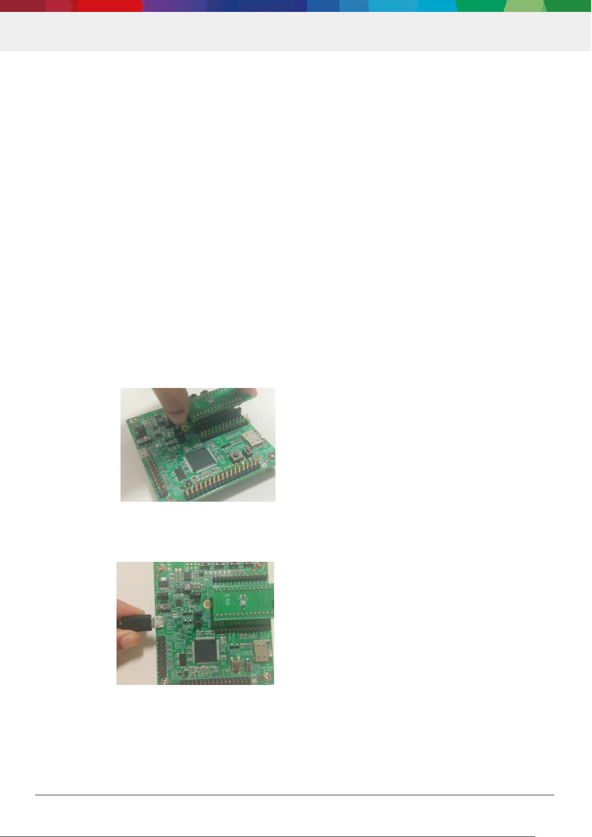
The procedure to connect sensor to PC via USB is as below:
1. Install DD2.0 UI.
2. Insert the shuttle board and application board.
3. Connect the board and PC using a USB cable/Bluetooth.
Figure 1 : Insert sensor
Figure 2 : Connect board and PC

Bosch Sensortec | BMX055 User Manual 8 | 35
Modifications reserved | Data subject to change without notice Document number: BST-BMX055-SD000-00
4. Turn the on/off switch ON. The LED glows.
3.2 Startup View
To start the DD2.0 UI software:
Click Start -> Programs -> Development Desktop 2.0.
Or
Double click the DD2.0 UI software icon on the desktop.
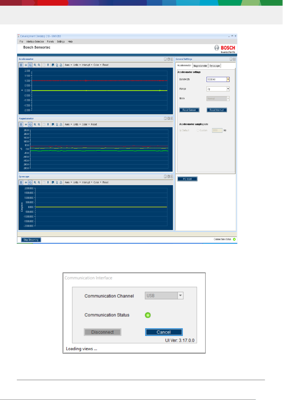
The Graphical User Interface (GUI) of the software is as seen below:
Figure 3 : Connection complete
Bosch Sensortec | BMX055 User Manual 9 | 35
Modifications reserved | Data subject to change without notice Document number: BST-BMX055-SD000-00
Figure 4 : DD2.0 UI Startup View
When the PC and board are connected, the Communication Status glows green as shown below:
Figure 5 : Communication Status
Bosch Sensortec | BMX055 User Manual 10 | 35
Modifications reserved | Data subject to change without notice Document number: BST-BMX055-SD000-00
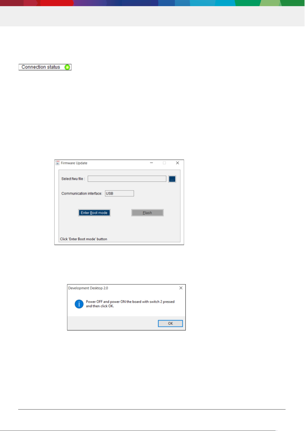
The communication status is also indicated at the bottom right of the GUI at all times:
Other menu options include:
o File
o Interface Selection
o Panels
o Settings
o Help
These menu options are explained in detail in the following sections.
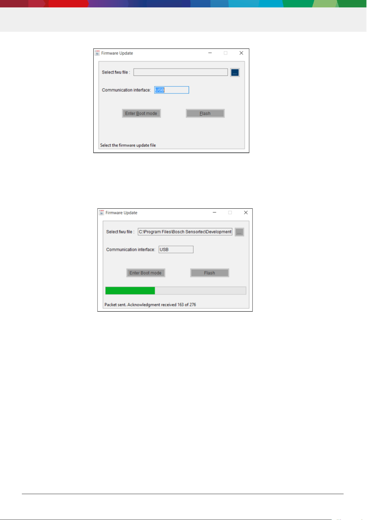
3.3 Upgrading Firmware
To upgrade the firmware of DD2.0 UI to match the current version, follow the steps below:
1. Click Menu -> Settings-> Firmware Upgrade. The following window appears:
2. Click Enter Boot mode.
3. Switch off board, and press Switch 2.In Application board, all four LEDs will glow simultaneously.
4. Click OK.
5. All four LEDs will glow simultaneously.
6. Press OK.
Figure 6 : Firmware upgrade window
Figure 7 : Application Boot Loader
Bosch Sensortec | BMX055 User Manual 11 | 35
Modifications reserved | Data subject to change without notice Document number: BST-BMX055-SD000-00
7. Select the default firmware update file (*.fwu2) from the DD2.0 UI installation directory in the folder Firmware.
8. Click Flash.
9. Once firmware upgrade is complete, restart the application board, and DD2.0 UI.
4. Working with Development Desktop 2.0 - BMX055 sensor
Development Desktop 2.0 offers complete access to BMX055 sensor.
4.1 Sensor Data and Interrupts Monitoring
BMX055 sensor compromises of Accelerometer, Gyroscope and Magnetometer in a single package and the
acceleration, gyro and magnetic field sensor signals can be monitored.
4.1.1 Accelerometer
This panel plots real time sensor signals from the accelerometer on the graph. The sensor data can be
analyzed by using graph features like Play/Pause, view history, graph speed, Zoom In/Out, Zoom particular area in the
graph, save and print current instance.
Figure 8 : Boot mode Detected
Figure 9 : Firmware upgrade completion
 Loading...