

Bosch BMS-BAC User Manual

6720862469 (16/04)
Before using your bacnet, please read this manual carefully and keep it for future reference.
CLIMATE 5000 VRF
Building Management System Gateway Card (Bacnet)
BMS-BAC
User manual

CONTENTS
1. CONNECTING DIAGRAM ..................................................3
2. FUNCTION DESCRIPTION ................................................3
3. CONFIGURATION ILLUSTRATION ...................................... 3
4. OBJECT TABEL ...............................................................4
2 | CONTENTS
6720862469 (16/04) CLIMATE 5000 VRF
1. CONNECTING DIAGRAM
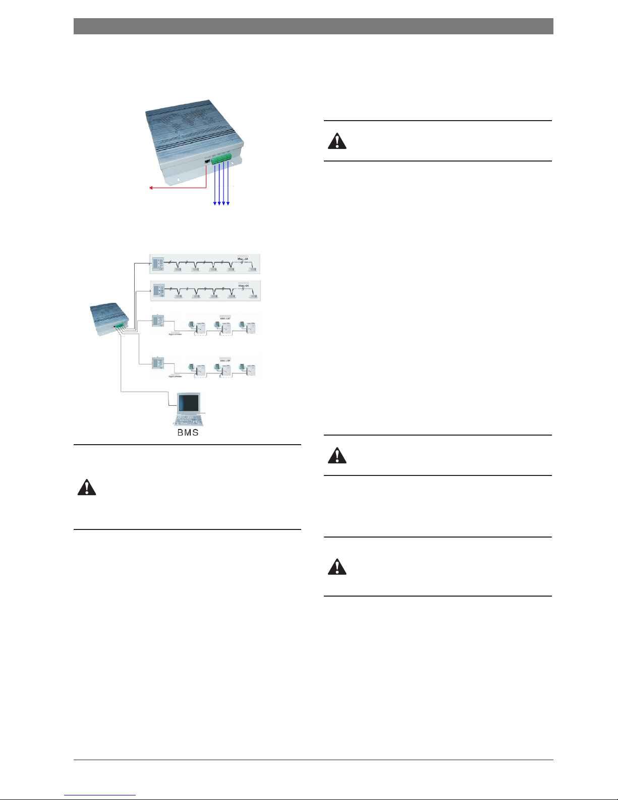
1.1. BMS-BAC interfaces illustration
Ethernet interface, connect with BACnet/
IP network
1.2. System connecting illustration
CAUTION
1) BMS-BAC net can connect to the centralised controller, or the
outdoor master unit. The address on the centralised controller
must be (0) and the outdoor master unit must be set to (16).
2) BMS-BAC net series must connect with Building Control
System with the same IPsubnet! Otherwise the unit will not work
correctly.
2. FUNCTION DESCRIPTION
This unit must be installed between the air conditioning system and
the BMS. BACnet interfaces create a way for air conditioning systems
to communicate with a BMS.
Once BACnet is configured correctly, any units connected to the
system will be able to be controlled and read with a BMS.
2.1. Operation control
This unit will provide the BMS with seven setting functions including
‘operation mode selection’, ‘time on setting’, ‘time off setting’, ‘swing
function’. Refer to object table for more information.
CAUTION
There will be a 10-20 second delay for the BMS to send or read
information.
3. CONFIGURATION ILLUSTRATION
Before using the BACnet, an initial setting configuration is required.
After installation is complete, you will need to input the IP address of
the BACnet into a web browser.
3.1. Control setting
The local network code range will be between 0 and 63. The name
of the network will automatically configure, which can be changed
to something more memorable. After the demand has been set
andthe equipment has been restarted, the equipment will modify the
changes. The control code has been set randomly before ex-factory,
“*” means of control code in“CONTROL-UNIT-*”.
3.2. Time and date setting
You can set the time and date to all corresponding systems connected
to the BACnet. After setting the time and date, the system will require
restarting.
3.3. Safe setting
If the controller requires resetting this can be achieved by using the
default admin password. Default administrator name is “admin” and
the passwordis“12345”.
CAUTION
For safety, passwords should be changed from the factory set
ones.
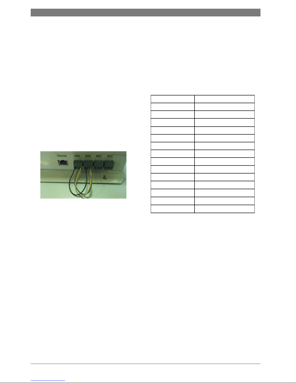
3.4. Network setting
This device adapts Ethernet as the network interface. An IP address
of ‘192.168.1.8’ has been factory set which must be modified to the
appropriate network address.
CAUTION
BMS BAC net series must connect with a Building Control System
using the same IP subnet. Once IP has configured, click ‘apply’
and restart the equipment.
Four groups of 485 interfaces, each one connects with a
universal centralised monitor controller or Indoor/Outdoor
conditioning unit.
BMS-BAC
F1 F2 E
Indoor Central Controller
Outdoor Central Controller
BACnet/IP Network
CLIMATE 5000 VRF 6720862469 (16/04)
CONNECTING DIAGRAM | 3
3.5. BACnet setting
The BACnet network code represents only one of the BACnet
centralised controllers in the range between 0 to 65535. Once the
address has been set, the device will need to be reset for the changes
to be effective.
Each BACnet has a unique network number. This BACnet network
number is required when multiple BACnet or centralised controllers
are connected.
The calculation formula for the indoor and outdoor air conditioning
units are:
Device ID=BTXX;
B is the bus Number 0-3;
T means type 0-indoor unit,1-outdoor unit;
XX is the indoor unit Number 0-63 or outdoor unit 0-31;
3.6. Factory Reset
To delete settings and return to factory setting, connect 1 and 2 of
485. This will restore factory settings of the BACnet.
4. OBJECT TABEL
This device provides with different objects tables for the different
types of outdoor units which are in using for the VRF system. System
will automatically identify using outdoor unit and generate the BACnet
object.
4.1. Indoor objects
This equipment provides with fourteen types of BACnet object, show
as the following table, for connecting with indoor unit using in the
Building Management System (BMS) or other system which suitable
for BACnet Protocol.
Number
Content
1
Device Information
2
Operation mode
3
Fan state
4
Preset Temperature
5
Indoor temperature
6
Set on time
7
Set off time
8
Swing function
9
Electric heater function
10
Malfunction state
11
Protection state
12
Mode query
13
Speed query
14
Temp set query
4 | OBJECT TABEL
6720862469 (16/04) CLIMATE 5000 VRF

Detailed infromation of corresponding objects refer to under-table
1) Device infromation
Attribute Identifier Data mode Attribute value Read/write
Object Identifier BACnetObjectIdentifier Device + Acnumber R
Object Name CharacterString Indoor * * R
Object Type BACnetObjectType Device R
Device Status BACnetDeviceStatus Operational R
Producer Name CharacterString AC Inc R
Producer Identifier Unisgned16 1 1 1 (Unsigned) R
Model Name CharacterString Get one of these from protocolanalysis: Wall Mounted Tpye Floor Tpye Embedded
Tpye Duct Tpye Floor&ceiling Tpye AC Auxiliary Machine Tpye Digital Mutilconnection Tpye Frequency Conversion Tpye Digital Rotation Tpye
R
Firmware Edition CharacterString 1.0 R
Application Software Edition CharacterString 1.0 R
Protocol Edition Unsigned 1 R
Protocol Correspondency Type Unsigned 3 R
Protocol Service Support BACnetServiceSupport ReadProperty R
Protocol Object Types Support BACnetObjectTypesSupport AnalogInput R
Object Array BACnetArray[n] Array all object R
Max length of APDU support Unsigned 1476 R
Segmentation support BACnetSegmentation Segmented both(0) R
Local Time Time R/W
Local Date Date R/W
APDU Segmentation Timeover Unsigned 2000 O
APDU Timeover Unsigned 3000 R
APDU Resend Times Unsigned 3 R
Device Address Binding AddressBinding ASN.1 ‘’ R
Operation instruction The CURRENT VALUE attribute of the selected object reflects the COMPRESSOR 1 ELECTRIC CURRENT (it’s unsettable). The
MINIMAL VALUE stands for the MINIMUM ELECTRIC CURRENT, while the MAXMUN VALUE stands for the MAXIMUM ELECTRIC
CURRENT.
2) Running mode
Attribute Identifier Data mode Attribute value Read/write
Object Identifier BACnetObjectIdentifier Multistate-output 1 R
Object Name CharacterString AC_OModeSetting R
Object Type BACnetObjectType Multistate-output R
Description CharacterString Operation mode setting O
Current value Unsigned W
Status Flags BACnetStatusFlags F F F F R
Event states BACnet EventStates Normal R
Take off service BOOLEAN F R
States number Unsigned 6 R
States text BACnet ARRAY[N]
CharacterString
Auto
Cool
Heat
Dehumidify
FanOnly
Stop
O
Priority Array BACnetPriorityArra NULL R
Release default Unsigned 0 R
Time delay Unsigned 2 O
Publicly type Unsigned 1701 O
Feedback value Unsigned 6
CLIMATE 5000 VRF 6720862469 (16/04)
OBJECT TABEL | 5

Event enable BACnetEventTransitionBits T T T O
Affirm transform BACnetEventTransitionBits T T T O
Notify Type BACnetNotifyType alarm O
Operation instruction The CURRENT VALUE attribute of the selected object reflects the current OPERATION MODE (it’s writeable and settable).
Thereinto, the CURRENT VALUE 1 means HEATING MODE; the CURRENT VALUE 2 means COOLING MODE; the CURRENT
VALUE 3 means DEHUMIDIFIED MODE; the CURRENT VALUE 4 means AIR SUPPLY; the CURRENT VALUE 5 means AUTO MODE;
the CURRENT VALUE 6 means SHUT OFF.
3) Fan states
Attribute Identifier Data mode Attribute value Read/write
Object Identifier BACnetObjectIdentifier Multistate-output 2 R
Object Name CharacterString AC _OFanSpeed R
Object Type BACnetObjectType Multistate-output R
Description CharacterString Fan Speed Setting O
Current value Unsigned W
Status Flags BACnetStatusFlags F F F F R
Event states BACnet EventStates Normal R
Take off service BOOLEAN F R
States number Unsigned 5 R
States text BACnet ARRAY[N]
CharacterString
Auto
Low
Middle
High
Stop
O
Priority Array BACnetPriorityArra NULL R
Release default Unsigned 5 R
Time delay Unsigned 1 O
Publicly type Unsigned 1701 O
Feedback value Unsigned 5
Event enable BACnetEventTransitionBits T T T O
Affirm transform BACnetEventTransitionBits T T T O
Notify Type BACnetNotifyType alarm O
Operation instruction The CURRENT VALUE attribute of the selected object reflects the current FAN SPEED (It’s writable and settable). Thereinto,
the CURRENT VALUE 1 means HIGH SPEED; the CURRENT VALUE 2 means MEDIUM SPEED; the CURRENT VALUE 3 means
LOW SPEED; the CURRENT VALUE 4 means AUTO SPEED; the CURRENT VALUE 5 means FAN STOP. The thing is, during air
conditioner operating, the CURRENT VALUE would be set as to 5 (the order of stop the fan) for ensuring the normal operate,
however, this default setting would be omitted by the system automatically.
4) Preset temperature
Attribute Identifier Data mode Attribute value Read/write
Object Identifier BACnetObjectIdentifier Analog-output 1 R
Object Name CharacterString AC_OTempSetting R
Object Type BACnetObjectType Analog-output R
Current value REAL W
Description CharacterString Temperature Setting O
Status Flags BACnetStatusFlags F F F F R
Event states BACnet EventStates Normal R
Take off service BOOLEAN F R
Unit BACnetEngineering Units Degree-Celsius R
Minimum REAL 16 O
Maximum REAL 32 O
Priority array Value BACnetPriorityArra NULL R
Default release REAL 25 R
Distinguishability REAL 1 O
COV increment REAL 1 O
6 | OBJECT TABEL
6720862469 (16/04) CLIMATE 5000 VRF
 Loading...