

Bosch BMS500-AAU012-0AHXXA, BMS500-AAS012-0CSXXA, BMS500-AAS009-1CSXXA, BMS500-AAS012-1CSXXA, BMS500-AAS009-0CSXXA Service Manual
...
Bosch Split-Type Ductless Air Conditioner / Heat Pump
Climate 5000 AA Series
Service Manual

|
2
Bosch Climate 5000 AA Series Split Type Ductless Air Conditioner / Heat Pump Service Manual
Data subject to change
02.2018 | Bosch Thermotechnology Corp.
Service Manual Bosch Climate 5000 AA Series Split Type Ductless Air Conditioner / Heat Pump | 3
Table of Contents
1 Key to Symbols and Safety Instructions 4
1.1 Key to symbols 4
1.2 Safety 4
2 Part Names and Model Numbers 6
2.1 Model numbers 6
2.2 Unit parts 6
3 Dimensions 7
3.1 Indoor unit 7
3.2 Outdoor unit 9
4 Refrigerant Cycle Diagram 10
5 Wiring Diagram 12
6 Installation Details 12
8 Troubleshooting 22
8.1 Indoor unit error display 23
8.2 Outdoor unit error display 24
8.3 Diagnosis and solution 28
9 Disassembly Guide 50
9.1 Indoor unit 50
9.2 Outdoor unit 55
10 Care and Maintenance 70
10.1 Cleaning precautions 70
10.2 Cleaning your air À lter 70
10.3 Air À lter reminders (optional) 71
10.4 Maintenance – long periods of non-use 71
10.5 Maintenance – pre-season inspection 71
6.1 Wrench torque sheet for installation 12
6.2 Connecting the cables 12
6.3 Pipe length and the elevation 12
6.4 First time installation 12
6.5 Adding the refrigerant to an existing system 13
6.6 Re-installation / indoor unit needs to be repaired 13
6.7 Re-installation while the outdoor unit needs to be repaired 14
6.8 Operation characteristics 15
7 Electronic Functions 16
7.1 Abbreviation 16
7.2 Display function 16
7.3 Main protection 16
7.4 Operation modes and functions 17
Bosch Thermotechnology Corp. | 02.2018
Data subject to change
|
4
Bosch Climate 5000 AA Series Split Type Ductless Air Conditioner / Heat Pump Service Manual
1 Key to Symbols and Safety Instructions
1.1 Key to symbols
Warnings
Warnings in this document are identifi ed by a
warning triangle printed against a grey background.
Keywords at the start of a warning indicate the type and seriousness
of the ensuing risk if measures to prevent the risk are not taken.
The following keywords are defi ned and can be used in this document:
f DANGER indicates a hazardous situation which, if not avoided, will result
in death or serious injury.
f WARNING indicates a hazardous situation which, if not avoided, could
result in death or serious injury.
f CAUTION indicates a hazardous situation which, if not avoided, could
result in minor to moderate injury.
f NOTICE is used to address practices not related to personal injury.
1.2 Safety
Please read safety precautions before installation
WARNING:
f The information contained in the manual is intended for
use by a qualified service technician familiar with safety
procedures and equipped with the proper tools and test
instruments.
f Repairs made by unqualified persons can result in hazards to
you and others.
WARNING:
f Do not modify the length of the signal/power cable or use an
extension cord to power the unit.
f Do not share the electrical outlet with other appliances.
Improper or insufficient power supply can cause fire or
electrical shock.
Important information
This symbol indicates important information where
there is no risk to people or property.
WARNING:
f When connecting refrigerant piping, do not let substances or
gases other than the specified refrigerant enter the unit. The
presence of other gases or substances will lower the unit’s
capacity, and can cause abnormally high pressure in the
refrigeration cycle. This can cause explosion and injury.
WARNING:
f Installation MUST conform with local building codes or, in
the absence of local codes, with the National Electrical Code
NFPA70/ANSI C1-1993 or current edition and Canadian
Electrical Code Part1 CSA C.22.1.
WARNING:
f Failure to carefully read and follow all instructions in this
manual can result in equipment malfunction, property
damage, personal injury and/or death.
Data subject to change
02.2018 | Bosch Thermotechnology Corp.
Service Manual Bosch Climate 5000 AA Series Split Type Ductless Air Conditioner / Heat Pump | 5
WARNING: ELECTRICAL
f For all electrical work, follow all local and national wiring
standards, regulations, and the Installation Manual.
The power supply to the outdoor unit requires a service
disconnect at the unit. Only use a dedicated circuit. Never
share a power source connected to this system. Insufficient
electrical capacity or defects in electrical work can cause
electrical shock or fire.
f For all electrical work, use the specified cables. Connect
cables tightly, and clamp them securely to prevent external
forces from damaging the terminal. Improper electrical
connections can overheat and cause fire, and may also cause
shock.
f All wiring must be properly arranged to ensure that the
control board cover can close properly. If the control board
cover is not closed properly, it can lead to corrosion and
cause the connection points on the terminal to heat up, catch
fire, or cause electrical shock.
f If the power supply cord is damaged, it must be replaced
by the manufacturer, its service agent or similarly qualified
persons such as a licensed electrician in order to avoid a
hazard.
f The product must be properly grounded at the time of
installation, or electrical shock may occur.
CAUTION:
f Install condensate drainage piping according to the
instructions in this manual. Improper condensate drainage
may cause water damage to your home and property.
NOTICE: FLUORINATED GASSES [REFRIGERANT]
f This air-conditioning unit contains fluorinated gasses. For
specific information on the type of gas and the amount,
please refer to the relevant label on the outdoor unit itself.
f Installation, service, maintenance and repair of this unit must
be performed by a certified technician.
f Product removal and recycling must be performed by a
certified technician.
f If the system has a leak-detection system installed, it must be
checked for leaks at least every 12 months.
f When the unit is checked for leaks, proper record-keeping of
all checks is strongly recommended.
WARNING:
f Do not install unit in area of high heat such as kitchen, server
rooms, etc.
CAUTION:
f For units that have an auxiliary electric heater, do not install
the unit within 1 meter (3 feet) of any combustible materials.
f Do not install the unit in a location that may be exposed
to combustible gas leaks. If combustible gas accumulates
around the unit, it may cause fire.
f Do not operate your air conditioner in a wet room such as a
bathroom or laundry room. Too much exposure to water can
cause electrical components to short circuit.
NOTICE: FLUORINATED GASSES [REFRIGERANT]
f Air and moisture in the refrigerant system have undesirable
effects as below:
— Pressure in the system rises.
— Operating current rises.
— Cooling or heating efficiency drops.
— Moisture in the refrigerant circuit may freeze and block
capillary tubing.
— Water may lead to corrosion of parts in the refrigerant
system. Therefore, the indoor units and the pipes
between indoor and outdoor units must be leak tested
and evacuated to remove gas and moisture from the
system.
Bosch Thermotechnology Corp. | 02.2018
Data subject to change
|
6
Bosch Climate 5000 AA Series Split Type Ductless Air Conditioner / Heat Pump Service Manual
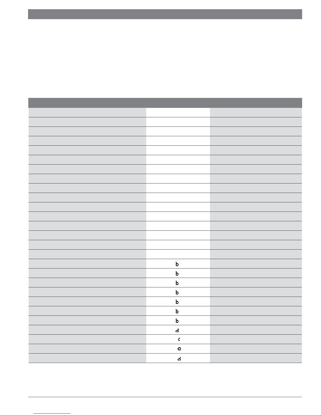
2 Part Names and Model Numbers
2.1 Model numbers
Capacity Voltage Indoor Units Outdoor Units
9k 115V BMS500-AAU009-0AHXXA BMS500-AAS009-0CSXXA
12k 115V BMS500-AAU012-0AHXXA BMS500-AAS012-0CSXXA
9k 208-230V BMS500-AAU009-1AHXXA BMS500-AAS009-1CSXXA
12k 208-230V BMS500-AAU012-1AHXXA BMS500-AAS012-1CSXXA
18k 208-230V BMS500-AAU018-1AHXXA BMS500-AAS018-1CSXXA
24k 208-230V BMS500-AAU024-1AHXXA BMS500-AAS024-1CSXXA
Table 1
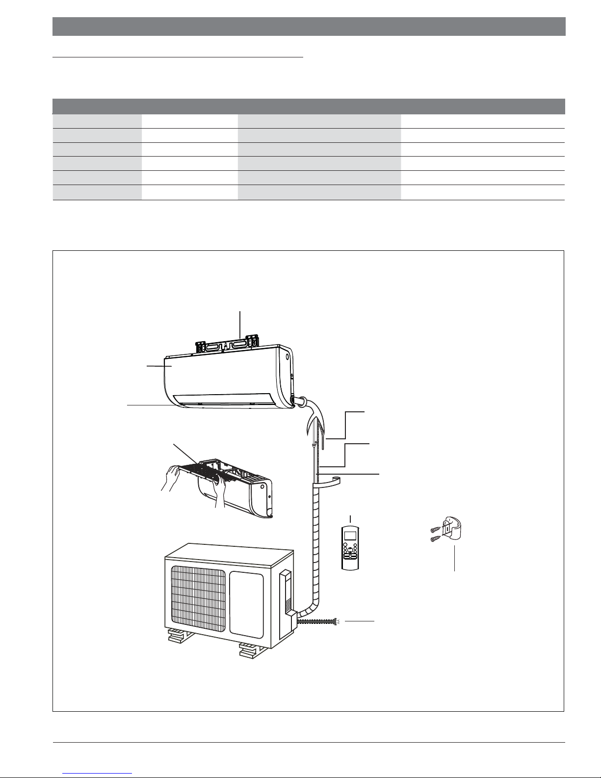
2.2 Unit parts
Wall Mounting Plate
Front Panel
Louver
Air filter
(pull it out)
Drainage Pipe
Signal/power Cable
(32ft cable included with indoor unit)
Refrigerant Piping
(Sold Separately)
Remote Control
Remote Holder
Outdoor Unit
Power Cable
(Required, not included with unit)
Figure 1
Data subject to change
02.2018 | Bosch Thermotechnology Corp.
Service Manual Bosch Climate 5000 AA Series Split Type Ductless Air Conditioner / Heat Pump | 7
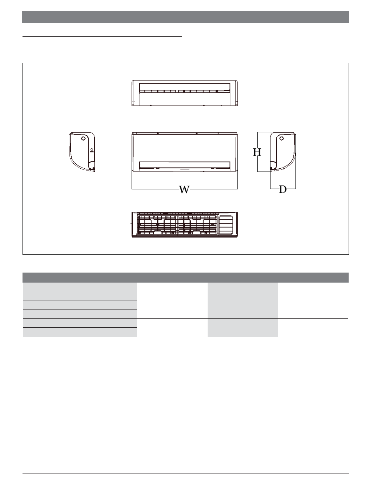
3 Dimensions
3.1 Indoor unit
Figure 2
Table 2
Model W x D x H (mm) W x D x H (inch) Mounted plate
BMS500-AAU009-0AHXXA
BMS500-AAU012-0AHXXA
BMS500-AAU009-1AHXXA
BMS500-AAU012-1AHXXA
BMS500-AAU018-1AHXXA
BMS500-AAU024-1AHXXA
805 x 193 x 302 31.69 x 7.60 x 11.89 B
1106 x 232 x 342 43.54 x 9.13 x 13.46 D
Bosch Thermotechnology Corp. | 02.2018
Data subject to change
|
8
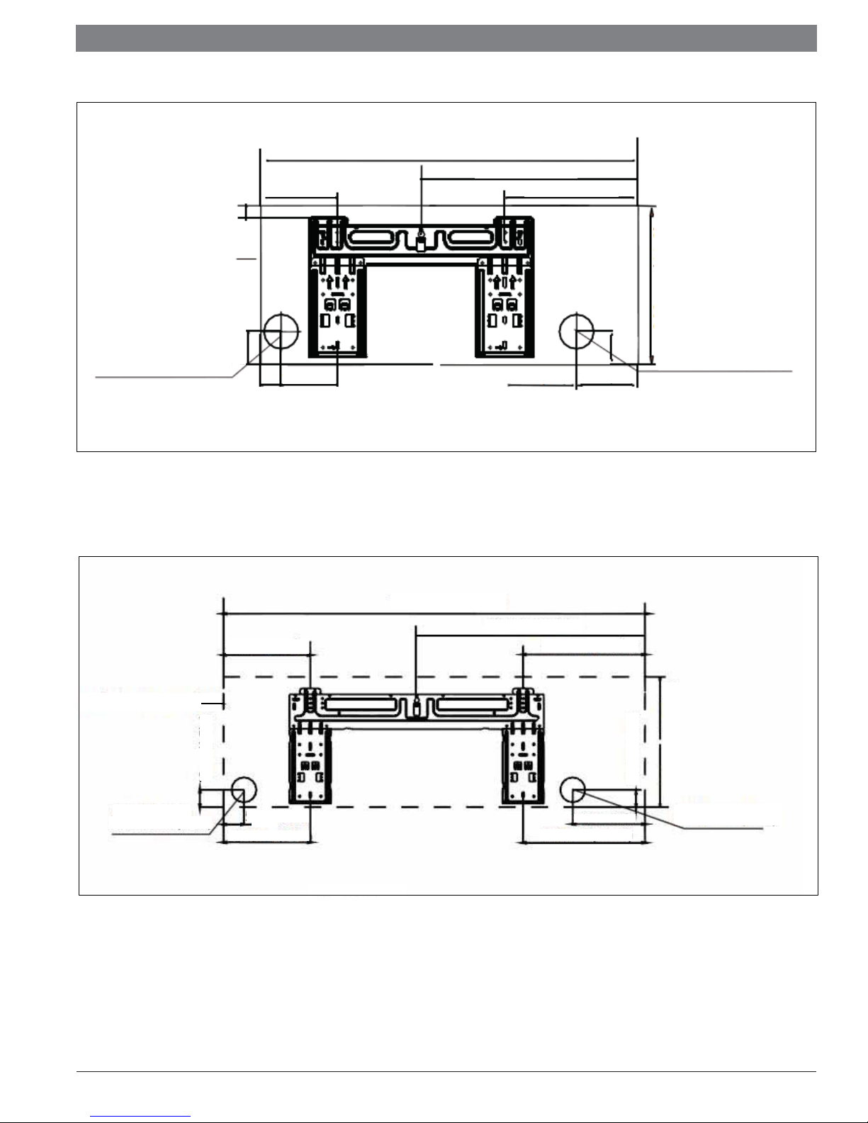
Bosch Climate 5000 AA Series Split Type Ductless Air Conditioner / Heat Pump Service Manual
31.7" (805mm)
16.8" (427.9mm)
6.5"(163mm)
1.1" (27mm)
8.8" (224.6mm)
Indoor unit outline
11.9" (302mm)
Left rear wall hole
2.5" (65mm)
Figure 3
For mount plate B
Indoor unit outline
2.1" (53mm)
1.5"
(39mm)
(128mm)
8.9"(228mm)
5.1"
43.5" (1106mm)
4.4"
(112mm)
23.6" (598.4mm)
12.5" (319.5mm)
4.5"
(113mm)
2.1" (53mm)
Right rear wall hole
2.5" (65mm)
1.7" (45mm)
Left rear wall hole
2.5" (65mm)
2.1"
(53.7mm)
8.9"(227.8mm)
Figure 4
For mount plate D
Data subject to change
7.4"(189mm)
12.5"(319.5mm)
13.5" (342mm)
1.7" (45mm)
Right rear wall hole
2.5" (65mm)
02.2018 | Bosch Thermotechnology Corp.
Service Manual Bosch Climate 5000 AA Series Split Type Ductless Air Conditioner / Heat Pump | 9
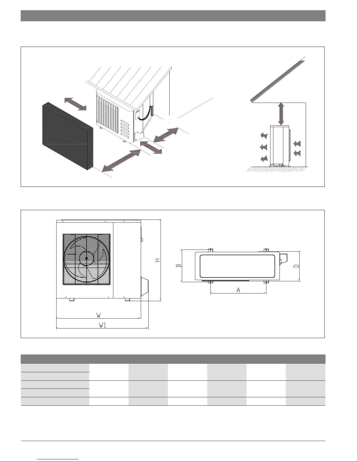
3.2 Outdoor unit
More than 30cm(11.8in)
More than 60cm(23.6in)
More than 30cm(11.8in)
Fence or
obstacles
More than 60cm(23.6in)
More than 70cm(27.6in)
(Service space)
Figure 5
Outdoor unit clearances
Figure 6 Outdoor unit dimensions
Model W D H W1 A B
BMS500-AAS009-0CSXXA
BMS500-AAS009-1CSXXA
BMS500-AAS012-0CSXXA
BMS500-AAS012-1CSXXA
BMS500-AAS018-1CSXXA 33.27 (845) 14.29 (363) 27.64 (702) 35.98 (914) 21.26 (540) 13.78 (350)
Table 3 Outdoor unit dimensions in inches (mm)
30.31 (770) 11.81 (300) 21.85 (555) 33.07 (840) 19.17 (487) 11.73 (298)
31.50 (800) 13.11 (333) 21.81 (554) 34.25 (870) 20.24 (514) 13.39 (340)
Bosch Thermotechnology Corp. | 02.2018
Data subject to change
|
10
Bosch Climate 5000 AA Series Split Type Ductless Air Conditioner / Heat Pump Service Manual
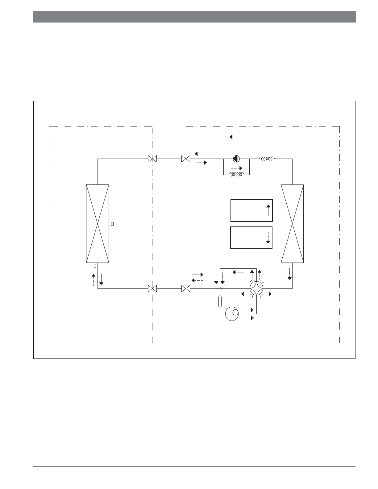
4 Refrigerant Cycle Diagram
For indoor models:
BMS500-AAU009-0AHXXA, BMS500-AAU012-0AHXXA,
For outdoor models:
BMS500-AAS009-0CSXXA, BMS500-AAS012-0CSXXA
INDOOR OUTDOOR
HEAT
EXCHANGER
T2 Evaporator
temp. sensor
T1 Room temp.
sensor
LIQUID SIDE
LIQUID
SERVICE
VALVE
GAS SIDE
GAS
SERVICE
VALVE
ACCUMULATOR
CHECK VALVE
(Heating Model only)
CAPILIARY TUBE
REFRIGERANT
FLOW IN
COOLING
REFRIGERANT
FLOW IN
HEATING
HEAT
EXCHANGER
REVERSING
VALVE
Figure 7
Refrigerant cycle diagram
Data subject to change
COMPRESSOR
02.2018 | Bosch Thermotechnology Corp.
Service Manual Bosch Climate 5000 AA Series Split Type Ductless Air Conditioner / Heat Pump | 11
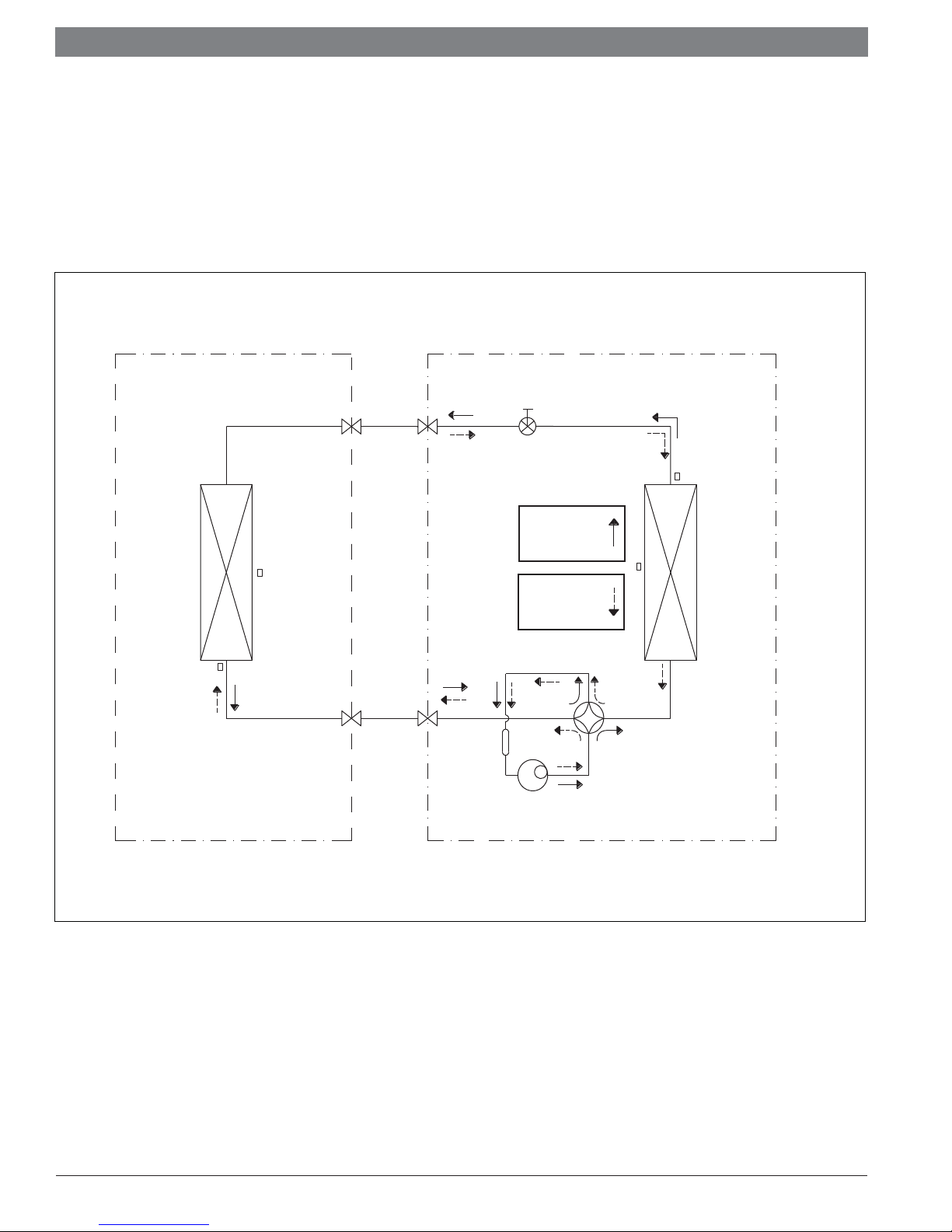
For indoor models:
BMS500-AAU009-1AHXXA, BMS500-AAU012-1AHXXA,
BMS500-AAU018-1AHXXA, BMS500-AAU024-1AHXXA,
For outdoor models:
BMS500-AAS009-1CSXXA, BMS500-AAS012-1CSXXA
BMS500-AAS018-1CSXXA, BMS500-AAS024-1CSXXA
INDOOR OUTDOOR
Electronic
LIQUID SIDE
LIQUID
SERVICE
VALVE
expansion valve
HEAT
EXCHANGER
Figure 8
Refrigerant cycle diagram
T2 Evaporator
temp. sensor
T1 Room temp.
sensor
GAS SIDE
GAS
SERVICE
VALVE
Accumulator
REFRIGERANT
FLOW IN
COOLING
REFRIGERANT
FLOW IN
HEATING
Compressor
HEAT
EXCHANGER
REVERSING
VALVE
Bosch Thermotechnology Corp. | 02.2018
Data subject to change
|
12
Bosch Climate 5000 AA Series Split Type Ductless Air Conditioner / Heat Pump Service Manual
5 Wiring Diagram
Refer to wiring diagram in the installation manual (IOM) or on the unit.
6 Installation Details
6.1 Wrench torque sheet for installation
Outside diameter Torque Additional tightening torque
Ф6.35mm 1/4in 1500N.cm(153kgf.cm) 1600N.cm(163kgf.cm)
Ф9.52mm 3/8in 2500N.cm(255kgf.cm) 2600N.cm(265kgf.cm)
Ф12.7mm 1/2in 3500N.cm(357kgf.cm) 3600N.cm(367kgf.cm)
Ф15.9mm 5/8in 4500N.cm(459kgf.cm) 4700N.cm(479kgf.cm)
Ф19mm 3/4in 6500N.cm(663kgf.cm) 6700N.cm(683kgf.cm)
Table 4
6.2 Connecting the cables
The power cord should be selected according to the following specifi cations sheet.
Appliance Amps AWG Wire Size
10 18
13 16
18 14
25 12
30 10
Table 5
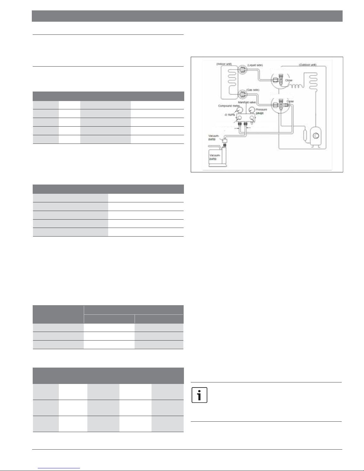
6.4 First time installation
Air purging with vacuum pump
Liquid service valve
Gas service valve
Shut-O Knob Low
Refrigerant Manifold,
Blue Hose
Figure 9
1. Completely tighten the fl are nuts of the indoor and outdoor units, confi rm
that both the liquid service and gas service valves are set to the closed
position.
2. Connect the refrigerant manifold, blue hose with the push pin of shut-off
knob of the low side to the gas service valve port.
3. Connect the refrigerant manifold, yellow hose to the shut-off high side
connection to the vacuum pump.
Shut-O Knob High
Charge/Refrigerant
Hose
The cable size and the current of the fuse or switch are determined by the maximum
current indicated on the nameplate which is located on the side panel of the
unit. Please refer to the nameplate before selecting the cable, fuse and switch.
Recommended: A means of disconnecting the power, should be within 10 feet of the
outdoor unit.
6.3 Pipe length and the elevation
Models
Gas Liquid
9K 3/8in (Ф9.52mm) 1/4in (Ф6.35mm)
12K,18K 1/2in (Ф12.7mm) 1/4in (Ф6.35mm)
24K 5/8in (Ф15.9mm) 3/8in (Ф9.52mm)
Table 6
Models
9K,12K
18K
24K
Standard
length
7.5m
(24.6ft)
7.5m
(24.6ft)
7.5m
(24.6ft)
Max.
Elevation
10m (32.8ft) 25m (82.0ft)
20m (65.6ft) 30m (98.4ft)
25m (82.0ft) 50m (164ft)
Table 7
Pipe size
Max. Length
A
Additional
refrigerant
15g/m
(0.16oz/ft)
15g/m
(0.16oz/ft)
30g/m
(0.32oz/ft)
4. Fully open the shut-off knob low side of the manifold valve.
5. Operate the vacuum pump to evacuate.
6. Perform evacuation for 30 minutes and check whether the refrigeration
low side pressure gauge indicates -0.1Mpa(14.5Psi). If the meter does not
indicate -0.1Mpa(14.5Psi) after evacuating for 30 minutes, it should be
evacuated 20 minutes more. If the pressure can’t achieve -0.1Mpa(14.5Psi)
after evacuating 50 minutes, please check if there are some leakage
points. Fully close the shut-off knob low side of the manifold and stop the
operation of the vacuum pump. Confi rm that the gauge needle does not move
(approximately 5 minutes after turning off the vacuum pump).
7. Make sure the pressure display in the pressure indicator is a little higher than
the atmospheric pressure. Then remove the charge hose from the gas service
valve.
8. Fully open the liquid service valve and gas service valve and securely tighten
the cap of the gas service valve. System is now evacuated and charged.
(Ensure that the unit is charged per the defi ned specifi cations).
Gas leak check (Use soap bubble method):
Apply soapy water or a liquid neutral detergent on the indoor unit
connections or outdoor unit connections by a soft brush to check for
leakage of the connecting points of the piping. If bubbles come out, the
pipes are leaking.
Data subject to change
02.2018 | Bosch Thermotechnology Corp.
Service Manual Bosch Climate 5000 AA Series Split Type Ductless Air Conditioner / Heat Pump | 13
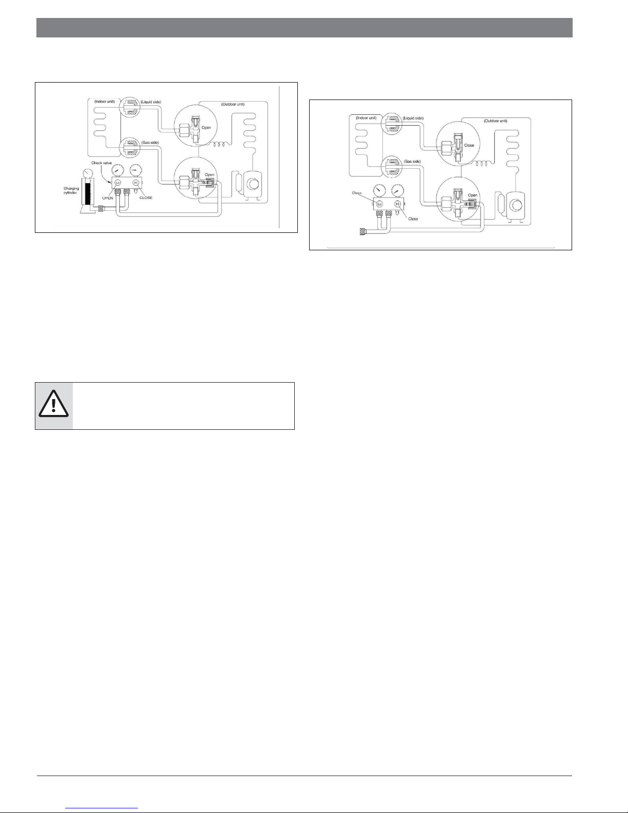
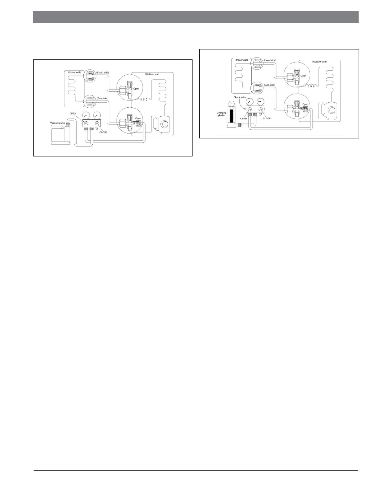
6.5 Adding the refrigerant to an existing system
Liquid service
valve
Gas service
valve
Figure 10
Procedure
1. Connect the refrigerant manifold, blue suction hose to the gas service
valve's service port, open the liquid service valve and the gas service valve.
Connect the refrigerant manifold, yellow hose to the valve at the bottom of the
cylinder. If the refrigerant is R410A, make the cylinder bottom up to ensure
liquid charge.
2. Purge the air from the refrigerant manifold, yellow hose. Open the valve at the
bottom of the cylinder and press the check valve on the refrigerant manifold
to purge the air.
CAUTION:
f Liquid refrigerant can cause frost bite. Handle with care.
6.6 Re-installation / indoor unit needs to be repaired
Collecting the refrigerant into the outdoor unit (passive recovery)
Liquid service
valve
Gas service
valve
Figure 11
Procedure
1. Remove the valve stem caps and confi rm that both the liquid and gas service
valves are set to the opened position. If not opened, use appropriate hex
wrench to open the valve stems.
2. Connect refrigerant gauge low side hose (blue) to the gas service valve's
service port
3. Air purging of the refrigerant manifold, blue hose: Open the low side valve of
manifold slightly to purge air from the hose for 5 seconds and then close it
quickly.
4. Set the liquid service valve to the close position.
3. Put the charging cylinder onto the electronic scale and record the weight.
4. Operate the air conditioner in cooling mode.
5. Open the valves (low side) on the refrigerant manifold and charge the system
with liquid refrigerant.
6. When the electronic scale displays the proper weight (refer to the gauge and
the pressure of the low side), turn off the refrigerant low side valve and the
refrigerant cylinder valve. Then turn off the unit to remove the hose from the
gas service valve.
7. Replace valve stem caps on the service port. Use a torque wrench to tighten
the service port cap to a torque of 18N.m. Be sure to check for gas leakage.
5. Operate the air conditioner at the cooling cycle and stop it when the gauge
indicates 0.1Mpa(14.5Psi).
6. Set the gas service valve to the closed position immediately. Do this quickly
so that the gauge ends up indicating 0.3Mpa(43.5Psi) to 0.5 Mpa(72.5Psi).
Disconnect the refrigerant manifold, and tighten the liquid and gas service
valve’s stem nuts. Use a torque wrench to tighten the gas service valve's
service port cap to a torque of 18N.m. Be sure to check for gas leakage.
Bosch Thermotechnology Corp. | 02.2018
Data subject to change
|
14
Bosch Climate 5000 AA Series Split Type Ductless Air Conditioner / Heat Pump Service Manual
6.7 Re-installation while the outdoor unit needs to be repaired
Evacuation for the whole system
Liquid service
valve
Gas service
valve
Figure 12
Procedure:
1. Confi rm that both the liquid and gas service valves are set to the opened
position.
2. Connect the vacuum pump to gas service valve’s service port.
3. Evacuate for approximately one hour. Confi rm that the refrigerant manifold
low side indicates -0.1Mpa(14.5Psi).
4. Close the valve (Low side) on the charge set, turn off the vacuum pump, and
confi rm that the gauge needle does not move (approximately 5 minutes after
turning off the vacuum pump).
5. Disconnect the charge hose from the vacuum pump.
Refrigerant charging
Liquid service
valve
Gas service
valve
Figure 13
Procedure:
1. Connect the charge hose to the charging cylinder, open the liquid and the
gas service valve. Connect the charge hose which you disconnected from the
vacuum pump to the valve at the bottom of the cylinder. If the refrigerant is
R410A, make the cylinder bottom up to ensure liquid charge.
2. Purge the air from the charge hose. Open the valve at the bottom of the
cylinder and press the check valve on the charge set to purge the air (be
careful of the liquid refrigerant).
3. Put the charging cylinder onto the electronic scale and record the weight.
4. Open the valves (Low side) on the refrigerant manifold and charge the system
with liquid refrigerant If the system cannot be charge with the specifi ed
amount of refrigerant, or can be charged with a little at a time (approximately
150g each time) , operating the air conditioner in the cooling cycle; however,
one time is not suffi cient, wait approximately 1 minute and then repeat the
procedure.
5. When the electronic scale displays the proper weight, disconnect the charge
hose from the gas service valve’s service port immediately. If the system has
been charged with liquid refrigerant while operating the air conditioner, turn
off the air conditioner before disconnecting the hose.
6. Mount the valve stem caps and the service port. Use torque wrench to tighten
the service port cap to a torque of 18N.m. Be sure to check for gas leakage.
Data subject to change
02.2018 | Bosch Thermotechnology Corp.
Service Manual Bosch Climate 5000 AA Series Split Type Ductless Air Conditioner / Heat Pump | 15
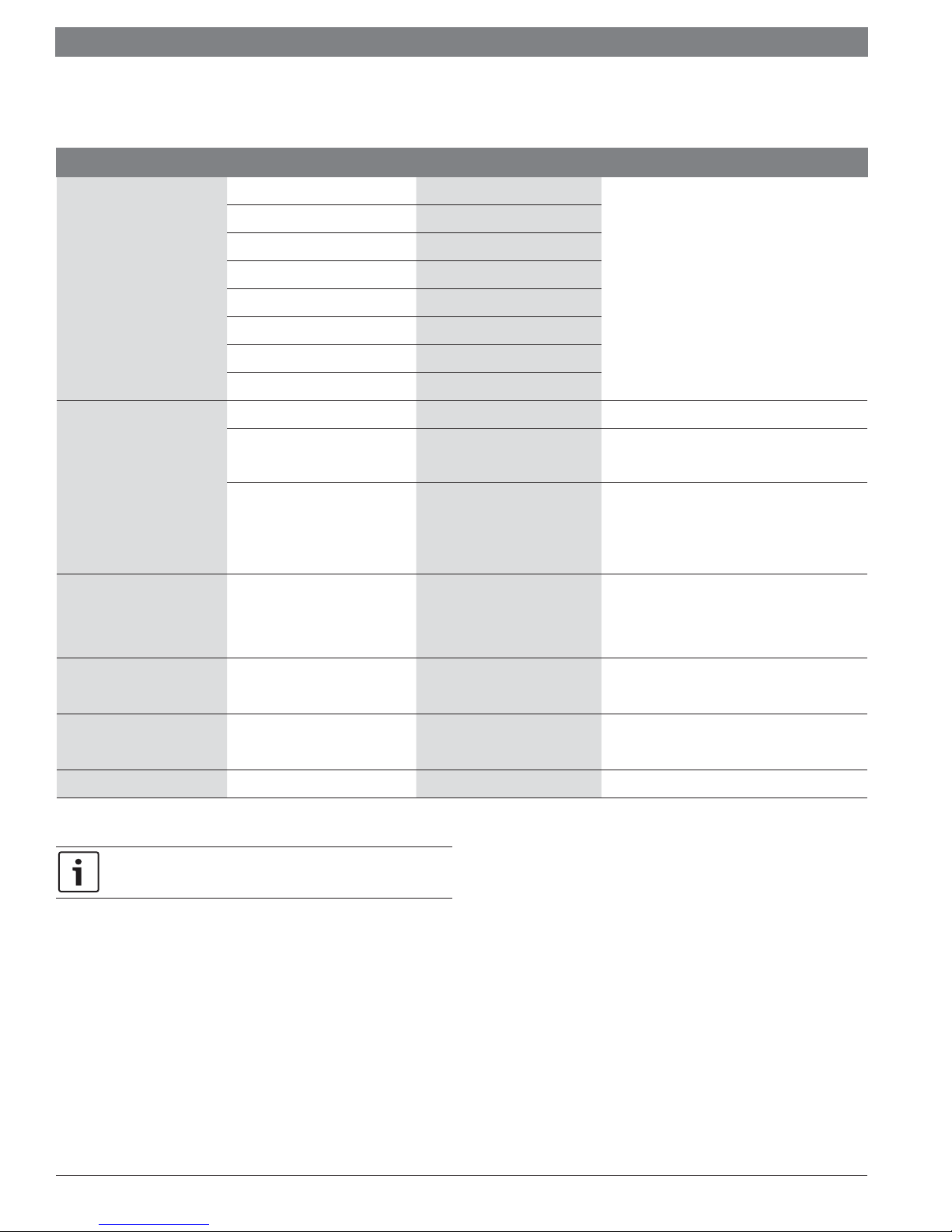
6.8 Operation characteristics
Temperature Cooling operation Heating operation Dr ying operation
Table 8
Room temperature
Outdoor temperature
BMS500-AAS009-0CSXXA
BMS500-AAS012-0CSXXA
BMS500-AAS009-1CSXXA
BMS500-AAS012-1CSXXA
BMS500-AAS018-1CSXXA
BMS500-AAS024-1CSXXA
62℉ - 90℉
(17℃ - 32℃)
-13°F - 122°F (-25°C - 50°C) -13°F - 122°F (-25°C - 50°C) 32°F-122°F (0°C-50°C)
32℉ - 86℉
(0℃ - 30℃)
50℉ - 90℉
(10℃ - 32℃)
Equation to convert Celsius to Fahrenheit
( °F) = 1.8 x ( °C) + 32
CAUTION:
f If the air conditioner is used beyond the above conditions,
certain safety protection features may come into operation
and cause the unit to operate abnormally.
f The room relative humidity should be less than 80%. If the air
conditioner operates beyond this figure, the surface of the air
conditioner may attract condensation. Please set the vertical
air flow louver to its maximum angle (vertically to the floor),
and set HIGH fan mode.
f The optimum performance will be achieved during this
operating temperature zone.
Bosch Thermotechnology Corp. | 02.2018
Data subject to change
|
16
Bosch Climate 5000 AA Series Split Type Ductless Air Conditioner / Heat Pump Service Manual
7 Electronic Functions
7.1 Abbreviation
T1: Indoor room temperature
T2: Coil temperature of evaporator
T3: Coil temperature of condenser
T4: Outdoor ambient temperature
T5: Compressor discharge temperature
Ts: Room temperature setting
Td: Off -set value (Td is an advanced feature)
T2b-A: suction temp for zone A in cooling (discharge temp for each zone in heating)
T2b-B: suction temp for zone B in cooling (discharge temp for each zone in heating)
T2b-C: suction temp for zone C in cooling (discharge temp for each zone in heating)
T2b-D: suction temp for zone D in cooling (discharge temp for each zone in heating)
T2b-E: suction temp for zone E in cooling (discharge temp for each zone in heating)
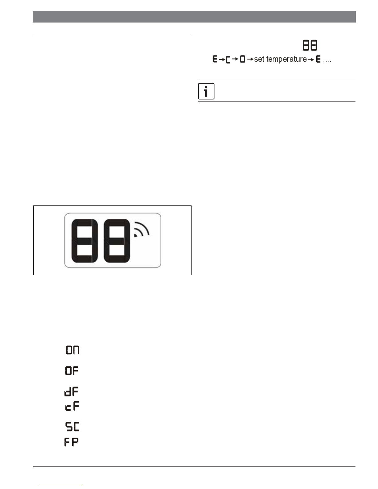
7.2 Display function
7.2.1 Icon explanation on indoor display board.
f When ECO function(optional) is activated,the “ ”
illuminates gradually one by one as
in one second intervals.
A guide on using the infrared remote is not included in this literature
package. A separate user guide is available for the remote operations.
7.3 Main protection
7.3.1 Three minutes delay at restart for compressor
1 minute delay for the 1st time start-up and 3 minutes delay for others.
7.3.2 Temperature protection of compressor discharge
Compressor discharge temp. T5> 239 °F (115℃) for 5s,compressor stops.
7.3.3 Fan speed is out of control
When indoor fan speed keeps too low (300RPM) for certain time, the unit will stop
and the LED will display the failure.
7.3.4 Inverter module protection
The Inverter module has a protection function about current, voltage and
temperature. If these protections happen, the corresponding code will display on
indoor unit and the unit will stop working.
Figure 14
Digital display:
f Displays the temperature settings when the air conditioner is operational.
f Displays the room temperature in FAN mode.
f Displays the self-diagnostic codes.
f Displays
or Silence feature is activated.
f Displays
feature is cancelled.
f Displays
f Displays when anti-cold air feature is activated under heating
mode.
f Displays
for three seconds when Timer ON, Fresh, Swing, Turbo
for three seconds when Fresh, Swing, Turbo or Silence
under defrosting operation (10min max).
during self clean operation (if applicable).
7.3.5 Indoor fan delayed open function
When the unit starts up, the louver will be active immediately and the indoor fan
will open 7s later. If the unit is running in heating mode, the indoor fan will be also
controlled by anti-cold air function.
7.3.6 Compressor preheating functions
Preheating permitting condition:
When T4(outdoor ambient temperature) 37.4 °F (3°C), the preheating function will
be activated.
7.3.7 Sensor protection at open circuit and breaking disconnection.
When there’s only one temperature sensor in malfunction , the air conditioner will
keep working but show the error code, in case of any emergency use.
When there’s more than one temperature sensor in malfunction, the air conditioner
will stop working.
f Displays and maintains a minimum temperature of 46°F (8°C) in
the space during heating operation.
Data subject to change
02.2018 | Bosch Thermotechnology Corp.
Service Manual Bosch Climate 5000 AA Series Split Type Ductless Air Conditioner / Heat Pump | 17
7.4 Operation modes and functions
7.4.1 Fan mode
(1) Outdoor fan and compressor stop.
(2) Temperature setting function is disabled and no setting temperature is displayed.
(3) Indoor fan can be set to high/med/low/auto.
(4) The louver operates same as in cooling mode.
(5) Auto fan:
7.4.2 Cooling mode
7.4.2.1 Compressor running rules
When T1-Ts<ΔT 3.6°F (2℃), the compressor will stop.
When T1—Ts >ΔT 0.9°F (0.5℃) the compressor will be activated.
ΔT is the programmed parameter of temperature compensation. This parameter is
preset at the factory.
When the AC run in mute mode, the compressor will run with low frequency. When
the current is more than setting value, the current protection function will be
activated, and the compressor will stop.
7.4.2.2 Outdoor fan running rules
The outdoor unit will run at diff erent fan speeds according to T4. For diff erent
outdoor units, the fan speeds are diff erent.
7.4.2.3 Indoor fan running rules
In cooling mode, indoor fan runs all the time and the speed can be selected as high,
medium, low and auto.
7.4.2.4 Condenser temperature protection
f TP3<T3< TP3+5, the compressor frequency will decrease to the lower
level until to F1 and then runs at F1.If TP3-3<T3< TP3, the compressor
will keep running at the current frequency.
7.4.3.4 Defrosting mode
AC will enter the defrosting mode according to the value of T3 and the value range of
change in T3 and also the compressor running time.
During the defrosting mode, the compressor will run, indoor and outdoor motor will
stop and defrost lamp of the indoor unit will be lighted
“
” will be displayed.
If any one of the following items is satisfi ed, the defrosting will fi nish and the machine
will turn to normal heating mode.
f T3 rises to be higher than TCDE 33.8°F (1℃).
f T3 keeps to be higher than TCDE 35.6°F (2℃) for 80 seconds.
f The machine has run for 15 minutes in defrosting mode.
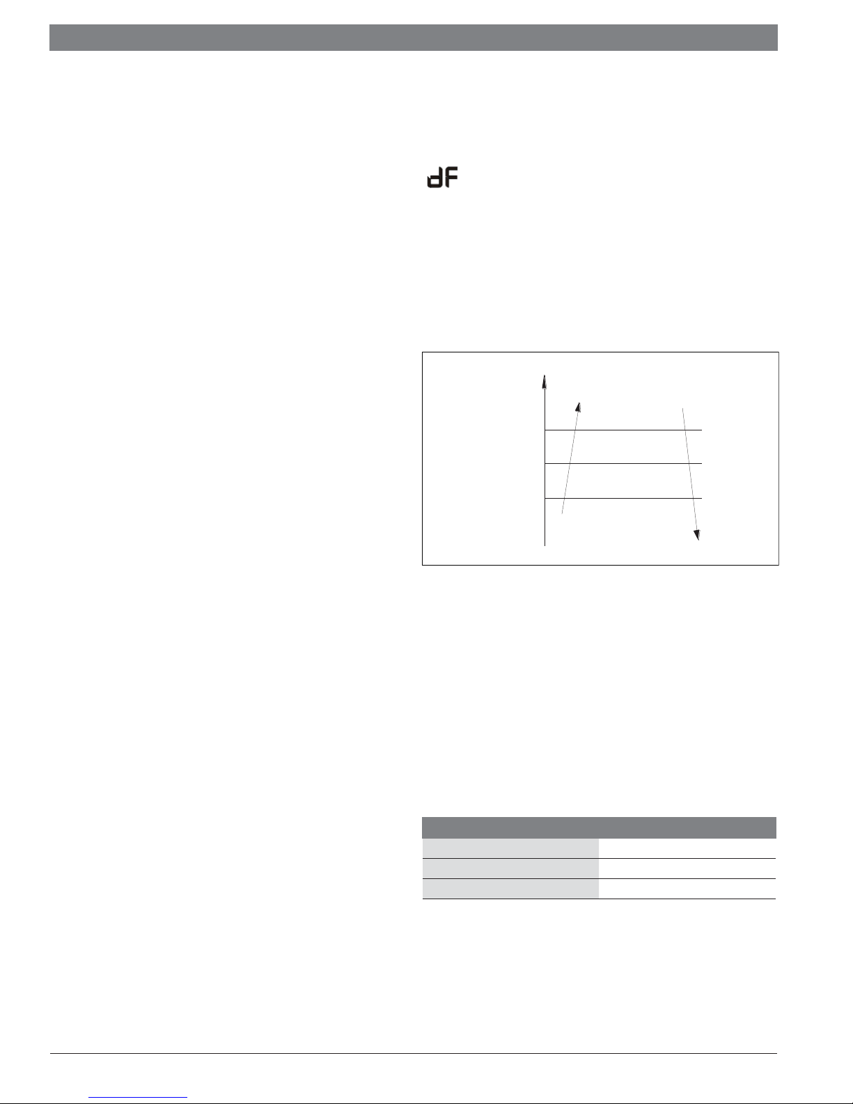
7.4.3.5 Evaporator coil temperature protection
T2
TEstop
TEdown
TEH2
Figure 15
Off
Decrease
Hold
Resume
f T3< TP3-3, the compressor will not limit the frequency and resume to the
former frequency.
f T3> TP3+5 for 5 seconds, the compressor will stop until T3< TP3-3.
7.4.2.5 Evaporator temperature protection
When Evaporator temperature is less than setting value, the compressor will stop.
7.4.3 Heating mode
7.4.3.1 Compressor operation
When T1-Ts>-ΔT, the compressor will stop.
When T1-TS<ΔT-2.8°F (1.5°C) the compressor will be on.
ΔT is the programmed parameter of temperature compensation.
When the AC runs in mute mode, the compressor will run with low frequency. When
the current is more than the setting value, the current protection function will be
activated and the compressor will stop.
7.4.3.2 Outdoor fan operation
The outdoor unit will be run at diff erent fan speed according to T4.
For diff erent outdoor units, the fan speeds are diff erent.
7.4.3.3 Indoor fan operation
When the compressor is on, the indoor fan can be set to high/med/low/auto and the
anti-cold wind function has the priority.
Off: Compressor stops.
Decrease: Decrease the running frequency to the lower level.
Hold: Keep the current frequency.
Resume: No limitation for frequency.
7.4.4 Auto-mode
This mode can be chosen with the remote controller and the setting temperature can
be changed between 62.6°F~86°F (17°C~30°C)
In auto mode, the machine will choose cooling, heating or fan-only mode according
to ΔT (ΔT =T1-Ts).
ΔT=T1-Ts Running mode
ΔT> 3.6°F (2℃) Cooling
-3.6°F (-2°C)≤ΔT≤ 3.6°F (2℃) Fan-only
ΔT< -3.6°F (-2℃) Heating
Table 9
Indoor fan will run at auto fan of the relevant mode.
The louver operates same as in relevant mode. If the machine switches mode
between heating and cooling, the compressor will keep stopping for 15 minutes and
then choose mode according to T1-Ts. If the setting temperature is modifi ed, the
machine will choose running function again.
Bosch Thermotechnology Corp. | 02.2018
Data subject to change

|
18
Bosch Climate 5000 AA Series Split Type Ductless Air Conditioner / Heat Pump Service Manual
7.4.5 Drying mode
Indoor fan speed is fi xed at breeze (low fan) and can’t be changed. The louver angle
is the same as in cooling mode.
All protections are active and the same as that in cooling mode.
7.4.6 Forced operation function
f Forced cooling mode: The compressor and outdoor fan keep running and
the indoor fan runs at low speed. After running for 30 minutes, AC will
turn to auto mode with 75.2°F (24℃) setting temperature.
f Forced auto mode: The action of forced auto mode is the same as normal
auto mode with 75.2°F (24℃) setting temperature.
When AC receives signals, such as switch on, switch off , timer on, timer off ,
mode setting, fan speed setting, sleeping mode setting, follow me setting, it
will quit the forced operation.
7.4.7 Timer function
f Timing range is 24 hours.
f Timer on. The machine will turn on automatically when reaching the setting
time.
f Timer off . The machine will turn off automatically when reaching the
setting time.
f Timer on/off . The machine will turn on automatically when reaching the
setting “on” time, and then turn off automatically when reaching the setting
“off ” time.
7.4.8 Sleep function
f The sleep function is available in cooling, heating or auto mode.
f Operation process in sleep mode is as follow:
When cooling, the setting temperature rises 1.8°F (1℃) (be lower than 86°F
(30℃)) every one hour, 2 hours later the setting temperature stops rising and
the indoor fan is fi xed at low speed.
When heating, the setting temperature decreases 1.8°F (1℃) (be higher than
62.6°F (17℃)) every one hour, 2 hours later the setting temperature stops
rising and indoor fan is fi xed at low speed. (Anti-cold wind function has the
priority).
f Operation time in sleep mode is 7 hours. After 7 hours, the AC will turn off
and sleep mode will also be turned off.
f Timer setting is available
7.4.9 Auto-restart function
The indoor unit is equipped with auto-restart function, which is carried out through
an auto-restart module. In case of a sudden power failure, the module memorizes
the setting conditions before the power failure. The unit will resume the previous
operation setting (not including swing function) automatically after 3 minutes when
power returns.
If the memorization condition is forced cooling mode, the unit will run in cooling
mode for 30 minutes and turn to auto mode as 75.2°F (24℃) setting temp.
If AC is off before power off and AC is required to start up now, the compressor will
have 1 minute delay when power on. Other conditions, the compressor will have 3
minutes delay when restarts.
f Timer off /on. The machine will turn off automatically when reaching the
setting “off ” time, and then turn on automatically when reaching the setting
“on” time.
f The timer function will not change the AC current operation mode.
Suppose AC is off now, it will not start up fi rstly after setting the “timer off ”
function. And when reaching the setting time, the timer LED will be off and
the AC running mode has not been changed.
f The setting time is relative time.
f The AC will quit the timer function when it has malfunction.
7.4.10 Refrigerant leakage detection
With this new technology, the display area will show “EC” when the outdoor unit
detects refrigerant leakage. This function is only available in cooling mode.
7.4.11 Louver position memory function
When starting the unit again after shutting down, its louver will restore to the angle
originally set by the user, but the precondition is that the angle must be within the
allowable range, if it exceeds, it will memorize the maximum angle of the louver.
During operation, if the power fails or the end user shuts down the unit in the turbo
mode, the louver will restore to the default angle.
7.4.12 46.4°F (8°C) heating
In heating operation, the preset temperature of the air conditioner can be as low as
46.4°F (8℃), which keeps the room temperature steady at 46.4°F (8℃)
and prevents household things freezing when the house is unoccupied for a long time
in severe cold weather. This 46.4°F (8℃) heating mode is activated from the remote
controller by pressing the FP button.
Data subject to change
02.2018 | Bosch Thermotechnology Corp.

Service Manual Bosch Climate 5000 AA Series Split Type Ductless Air Conditioner / Heat Pump | 19
7.4.13 Self clean(optional)
For heat pump models which are provided with this function, after running in cooling
or drying mode, if the user press “Self Clean” button on remote controller, fi rstly,
indoor unit runs in fan only mode for a while, then low heat operation and fi nally runs
in fan only again. This function can keep the inside of indoor unit dry and prevent
breeding of mold.
7.4.14 Follow me
1. If the indoor PCB receives the signal which results from pressing the
FOLLOW ME button on remote controller, the buzzer will emit a sound and
this indicates the follow me function is initiated. But when the indoor PCB
receives signal which sent from remote controller every 3 minutes, the
buzzer will not respond. When the unit is running with follow me function, the
PCB will control the unit according to the temperature from follow me signal,
and the temperature collection function of room temperature sensor will be
inactive, but the error detective function of room temperature sensor will be
still valid.
2. When the follow me function is available, the PCB will control the unit
according to the room temperature from the remote controller and the setting
temperature.
3. The PCB will take action to the mode change information from remote
controller signal, but it will not be aff ected by the setting temperature.
4. When the unit is running with follow me function, if the PCB doesn’t receive
any signal from remote controller for 7 minutes or pressing FOLLOW ME
button again, the follow me function will be turned off automatically, and the
temperature will control the unit according to the room temperature detected
from its own room temperature sensor and setting temperature.
7.4.15 Silence operation(optional)
Press the “silence” button on remote controller to initiate SILENCE function. When
the Silence function is activated, the compressor running frequency will keep lower
than F2 (compressor frequency) and the indoor unit will bring faint breeze, which will
reduce the noise to the lowest level and create a quiet and comfortable room for you.
Bosch Thermotechnology Corp. | 02.2018
Data subject to change
|
20
Bosch Climate 5000 AA Series Split Type Ductless Air Conditioner / Heat Pump Service Manual
7.4.16 Point check function (engineering troubleshooting mode)
Press the LED DISPLAY or LED or MUTE button of the remote controller three times,
and then press the AIR DIRECTION or SWING button three times in ten seconds,
the buzzer will keep ring for two seconds. The air conditioner will enter into the
information enquiry status. You can press the LED DISPLAY or AIR DIRECTION button
to check the next or front item’s information.
When the AC enter the “information enquiry” status, it will display the code name in 2
seconds, the details are as follows.
Enquiry information Displaying code Meaning
T1 T1 Indoor room temperature
T2 T2 Coil temperature of evaporator
T3 T3 Coil temperature of condenser
T4 T4 Outdoor ambient temperature
T2B Tb Coil temperature of evaporator
TP TP Compressor discharge temperature
TH TH Compressor suction temperature
Targeted Frequency FT Targeted Frequency
Actual Frequency Fr Actual Frequency
Indoor fan speed IF Indoor fan speed
Outdoor fan speed OF Outdoor fan speed
EXV opening angle LA EXV opening angle
Compressor continuous running time CT Compressor continuous running time
Causes of compressor stop. ST Causes of compressor stop.
Reserve A0
Reserve A1
Reserve
Reserve
Reserve
Reserve
Reserve
Reserve
Reserve
Reserve
0
1
2
3
4
5
6
L
Reserve A
Reserve U
Reserve
Table 10
Data subject to change
T
02.2018 | Bosch Thermotechnology Corp.
Service Manual Bosch Climate 5000 AA Series Split Type Ductless Air Conditioner / Heat Pump | 21
When the AC enter into information enquiry status, it will display code value in next
25s, the details are as follows:
Enquiry information Display value Meaning Remark
-1F,-1E,-1d,-1c,- 1b,-1A -25,-24,-23,-22,-21,-2, 0
-19—99 -19—99
A0,A1,…A9 100,101,…109
T1,T2,T3,T4, T2B,TP,TH,
Targeted Frequency,
Actual Frequency
Indoor fan speed
/Outdoor fan speed
EXV opening angle 0-FF
b0,b1,…b9 110,111,…119
c0,c1,…c9 120,121,…129
d0,d1,…d9 130,131,…139
E0,E1,…E9 140,141,…149
F0,F1,…F9 150,151,…159
0 OFF
1,2,3,4
14-FF
Low speed, Medium speed, High
speed, Turbo
Actual fan speed=Display value
turns to decimal value and then
multiply 10. The unit is RPM.
Actual EXV opening value=Display
value turns to decimal value and
then multiply 2.
1. All the displaying temperature is actual value.
2. All the temperature is °C no matter what kind
of remote controller is used.
3. T1,T2,T3,T4,T2B display range:-25~70,
TP display range:-20~130.
4. Frequency display range: 0~159HZ.
5. If the actual value exceeds the range, it will
display the maximum value or minimum value.
For some big capacity motors.
For some small capacity motors,
display value is from 14-FF(hexadecimal), the
corresponding fan speed range is from
200-2550RPM.
The min opening angle for the EXV is 0. The max
opening angle for EXV are diff erent for diff erent
model.
Compressor continuous
running time
Causes of compressor stop. 0-99
Reserve 0-FF
Table 11
0 - FF is a hexidecimal display value. Not OFF.
0-FF 0-255 minutes
For detailed meaning please
consult with manufacturer
If the actual value exceeds the range, it will display
the maximum value or minimum value.
Decimal display
Bosch Thermotechnology Corp. | 02.2018
Data subject to change
|
22
Bosch Climate 5000 AA Series Split Type Ductless Air Conditioner / Heat Pump Service Manual
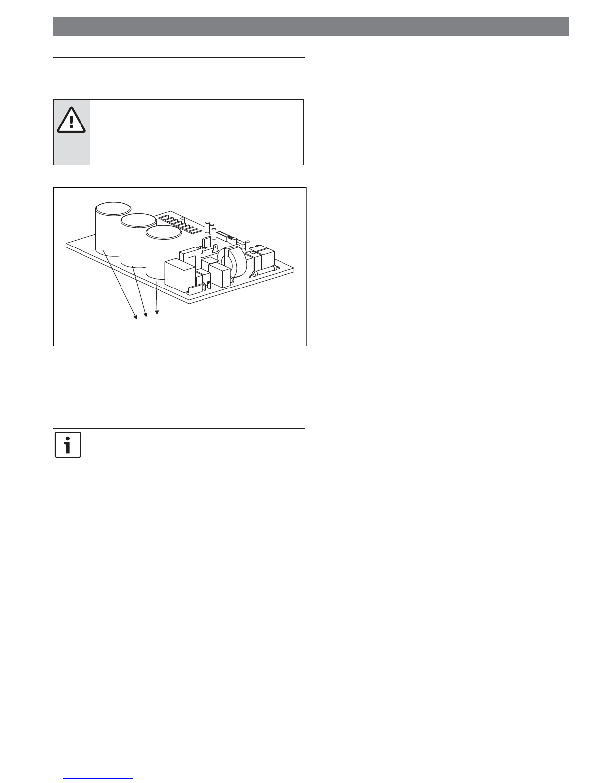
8 Troubleshooting
Safety
WARNING:
f Electricity power is still kept in capacitors even the power
supply is shut off . Do not forget to discharge the electricity
power in capacitor.
Electrolytic Capacitors
(HIGH VOLTAGE! CAUTION!)
Figure 16
For other models, please connect discharge resistance (approx.100Ω 40W)
between +, - terminals of the electrolytic capacitor on the opposite side of the
outdoor PCB. A screwdriver will also work as a resistive element.
For reference the most common error codes are E1, P0, and P3.
Data subject to change
02.2018 | Bosch Thermotechnology Corp.
 Loading...