

Bosch BMAC3036CNTD, BMAC2430BNTD, BMAC3036ANTD, BMAC3036BNTD, BMAC4248BNTF Installation Manual
...
Bosch Multi-Position Cased Coils
Cooling and Heat Pump Compatible
BMAC Series
Installation Manual

|
2
Bosch Multi-Position Cased Coils Installation Manual
03.2017 | Bosch Thermotechnology Corp.Data subject to change

Installation Manual Bosch Multi-Position Cased Coils | 3
Table of Contents
1 Key to symbols and safety instructions 4
1.2 Safety 4
2 General 5
2.1 Codes & regulations 5
2.2 Inspection upon unit arrival 5
2.3 Clearances 5
2.4 Dimensional data 6
3 Installation Instructions 9
3.1 Parts 9
3.2 Pre-installation instructions 9
3.3 Installation and trap connection 9
4 Drain application 10
4.1 Condensate drain piping 10
4.2 Plastic drain pan installation 10
5 Refrigerant connections 12
5.1 Airfl ow performance [CFM vs pressure drop]: 12
6 TXV replacement information 14
Bosch Thermotechnology Corp. | 03.2017
Data subject to change
|
4
Bosch Multi-Position Cased Coils Installation Manual
1 Key to symbols and safety instructions
1.1 Key to symbols
Warnings
Warnings in this document are identifi ed by a
warning triangle printed against a grey background.
Keywords at the start of a warning indicate the type and seriousness
of the ensuing risk if measures to prevent the risk are not taken.
The following keywords are defi ned and can be used in this document:
DANGER indicates a hazardous situation which, if not avoided, will result in
death or serious injury.
WARNING indicates a hazardous situation which, if not avoided, could
result in death or serious injury.
CAUTION indicates a hazardous situation which, if not avoided, could
result in minor to moderate injury.
NOTICE is used to address practices not related to personal injury.
Important information
This symbol indicates important information where
there is no risk to people or property.
1.2 Safety
Please read safety precautions before installation
WARNING:
These instructions are intended as an aid to qualified licensed
service personnel for proper installation, adjustment and
operation of this unit. Read these instructions thoroughly
before attempting installation or operation. Failure to follow
these instructions may result in improper installation,
adjustment, service or maintenance and possibly resulting
in fire, electrical shock, property damage, personal injury or
death.
WARNING:
Disconnect all power to the unit before starting any service
and maintenance. Failure to do so could cause severe
electrical shock resulting in personal injury or death.
WARNING: INSTALLATION REQUIREMENTS
Installation or servicing of this unit can be hazardous due
to parts, compo - nents and system pressure. Qualified and
proper trained service personnel should perform installation
and repai r . Failure to do so could cause severe electrical
shock resulting in personal injure or death.
03.2017 | Bosch Thermotechnology Corp.Data subject to change
Installation Manual Bosch Multi-Position Cased Coils | 5
2 General
These coils are approved for upfl ow or downfl ow, vertical and horizontal installation.
For furnace applications, the coil must be installed downstream (in the air outlet) of
the furnace.
2.1 Codes & regulations
This product is designed and manufactured to comply with national codes.
Installation in accordance with such codes and/or prevailing local codes/regulations
is the responsibility of the installer . The manufacturer assumes no responsibility for
equipment installed in violation of any codes or regulations.
The United States Environmental Protection Agency (EPA) has issued various
regulations regarding the introduction and disposal of refrigerants. Failure to follow
these regulations may harm the environment and can lead to the imposition of
substantial fi nes. Should you have any questions please contact the local offi ce of
the EPA.
2.2 Inspection upon unit arrival
As soon as unit is received, it should be inspected and noted for possible shipping
damage during transportation. It is carrier ’s responsibility to cover the cost
of shipping damage. Manufacturer or distributor will not accept a claim from
contractors for any transportation damage.
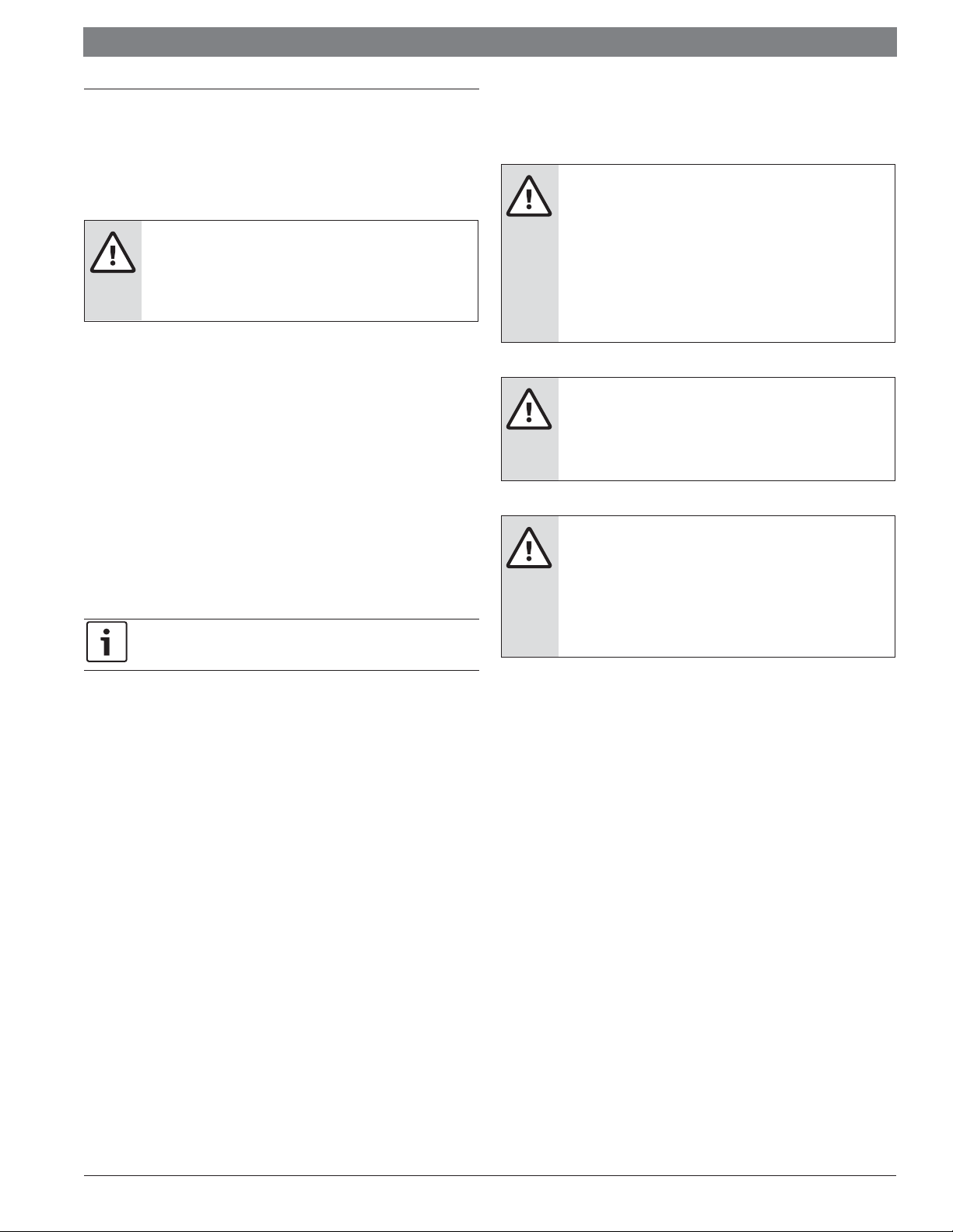
ıʾ
Front of unit
Figure 2 Clearance - top view (including air duct)
ıʾ
ı
ıʾ
2.3 Clearances
Following clearances should be provided during installation:
1. Maintenance and service access, including coil cleaning and coil assembly
removal
2. Refrigerant piping and connections
3. Condensate drain line
For ensure the proper installation, Select a solid and level site. Ensure enough space
required for installation and maintenance.
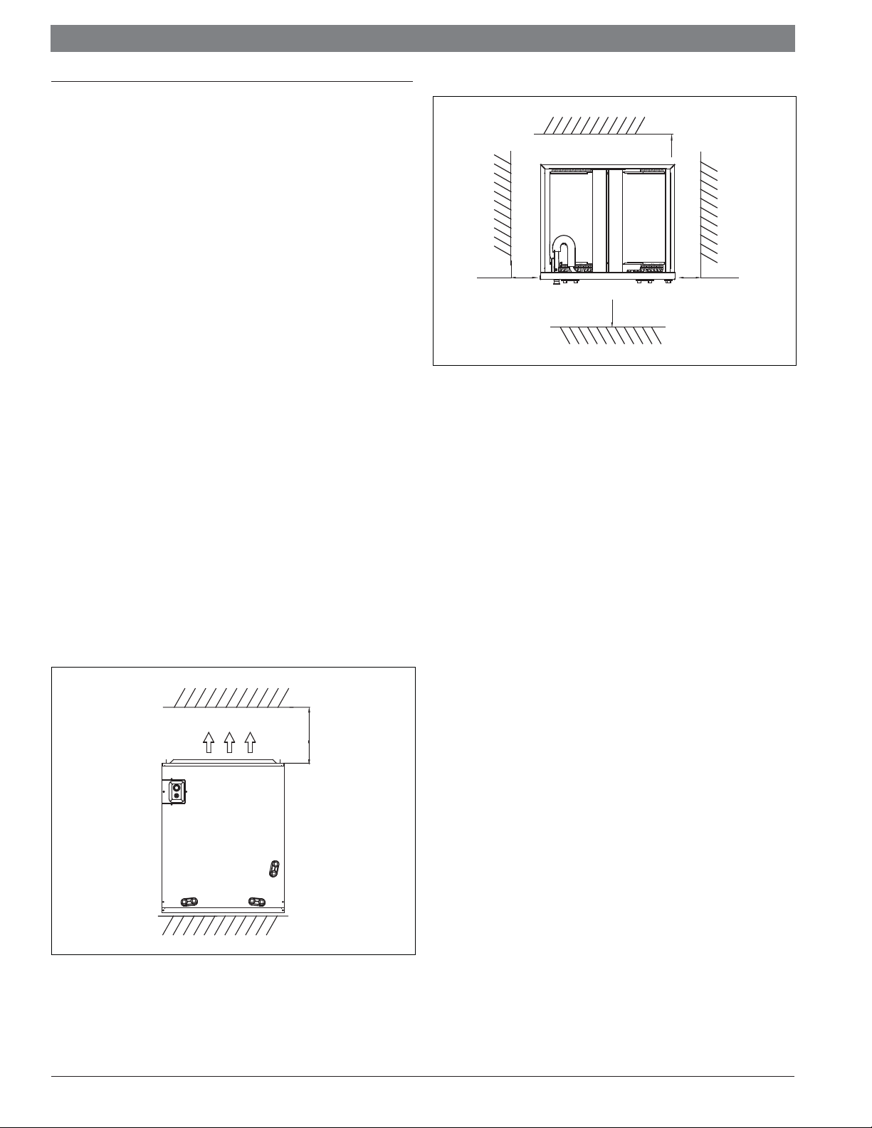
’
’ 0
2 ≥
AIRFLOW
Figure 1 Clearance -front view (including air duct)
Bosch Thermotechnology Corp. | 03.2017
Data subject to change
 Loading...