

Page 1
Pr
o
fess
io
nal
OBJ_DOKU-1021-002.fm Page 1 Friday, July 20, 2007 8:42 AM
Robert Bosch GmbH
Power Tools Division
70745 Leinfelden-Echterdingen
www.bosch-pt.com
1 609 929 L81 (2007.07) T / 268
BLE 200
Professional
BLE 200 Professional
Page 2
OBJ_BUCH-71-002.book Page 2 Friday, July 20, 2007 10:07 AM
2 |
de Originalbetriebsanleitung
en Original instructions
fr Notice originale
es Manual original
pt Manual original
it Istruzioni originali
nl Oorspronkelijke gebruiksaanwijzing
da Original brugsanvisning
sv Bruksanvisning i original
no Original driftsinstruks
fi Alkuperäiset ohjeet
el Πρωτότυπο οδηγιών χρήσης
tr Orijinal işletme talimat
jp
オリジナル取扱説明書
pl Instrukcją oryginalną
cs Původním návodem k používání
sk Pôvodný návod na použitie
hu Eredeti használati utasítás
ru Одлинник руководства по эксплуатации
uk Оригінальна інструкція з експлуатації
ro Instrucţiuni de folosire originale
bg Оригинално ръководство за експлоатация
sr Originalno uputstvo za rad
sl Izvirna navodila
hr Originalne upute za rad
et Algupärane kasutusjuhend
lv Instrukcijām oriģinālvalodā
lt Originali instrukcija
1 609 929 L81 | (20.7.07) Bosch Power Tools
Page 3
OBJ_BUCH-71-002.book Page 3 Friday, July 20, 2007 10:07 AM
3 |
Deutsch . . . . . . . . . . . . . . . . . . . . . . . . . . . Seite 6
English . . . . . . . . . . . . . . . . . . . . . . . . . . . . Page 16
Français . . . . . . . . . . . . . . . . . . . . . . . . . . . Page 26
Español . . . . . . . . . . . . . . . . . . . . . . . . . . Página 36
Português. . . . . . . . . . . . . . . . . . . . . . . . . Página 47
Italiano . . . . . . . . . . . . . . . . . . . . . . . . . . . Pagina 57
Nederlands. . . . . . . . . . . . . . . . . . . . . . . . Pagina 67
Dansk . . . . . . . . . . . . . . . . . . . . . . . . . . . . . . Side 76
Svenska . . . . . . . . . . . . . . . . . . . . . . . . . . . . Sida 85
Norsk . . . . . . . . . . . . . . . . . . . . . . . . . . . . . . Side 94
Suomi. . . . . . . . . . . . . . . . . . . . . . . . . . . . . . Sivu 102
Ελληνικά . . . . . . . . . . . . . . . . . . . . . . . . . . Σελίδα 111
Türkçe . . . . . . . . . . . . . . . . . . . . . . . . . . . . Sayfa 121
日本語 . . . . . . . . . . . . . . . . . . . . . . . . . . . . . ページ 130
Polski . . . . . . . . . . . . . . . . . . . . . . . . . . . . Strona 139
Česky . . . . . . . . . . . . . . . . . . . . . . . . . . . . Strana 149
Slovensky . . . . . . . . . . . . . . . . . . . . . . . . . Strana 158
Magyar . . . . . . . . . . . . . . . . . . . . . . . . . . . . Oldal 167
Русский . . . . . . . . . . . . . . . . . . . . . . . . Страница 176
Українська . . . . . . . . . . . . . . . . . . . . . . Сторінка 187
Română . . . . . . . . . . . . . . . . . . . . . . . . . . Pagina 196
Български . . . . . . . . . . . . . . . . . . . . . . Страница 205
Srpski. . . . . . . . . . . . . . . . . . . . . . . . . . . . Strana 214
Slovensko. . . . . . . . . . . . . . . . . . . . . . . . . . Stran 223
Hrvatski . . . . . . . . . . . . . . . . . . . . . . . . . Stranica 232
Eesti . . . . . . . . . . . . . . . . . . . . . . . . . . . Lehekülg 241
Latviešu . . . . . . . . . . . . . . . . . . . . . . . . . Lappuse 250
Lietuviškai . . . . . . . . . . . . . . . . . . . . . . . Puslapis 259
1 609 929 L81 | (20.7.07) Bosch Power Tools
Page 4
BLE
200
Pr
o
fe
s
s
i
o
na
l
B
L
E
20
0
P
ro
f
e
ss
i
o
n
al
BLE
200
Pr
o
fe
s
sio
na
l
OBJ_BUCH-71-002.book Page 4 Friday, July 20, 2007 10:07 AM
4 |
A
8
BLE 200
Professional
13
17
14
15
16
B
BLE 200
Profess
ional
BLE 200
Prof
essional
1 609 929 L81 | (20.7.07) Bosch Power Tools
Page 5
Pr
ofess
io
n
a
l
OBJ_BUCH-71-002.book Page 5 Friday, July 20, 2007 10:07 AM
5 |
8
9
10
1
2
3
4
5
BLE 200
Prof
ess
ional
6
7
3
2
1 609 929 L81 | (20.7.07) Bosch Power Tools
11
12
1D3
elden-Echterdingen
D-70745 Leinf
ert Bosch GmbH
Rob
Made in USA
Battery 2x1.5V LR6 (AA)
BLE200
8
4
Page 6
OBJ_DOKU-1023-002.fm Page 6 Friday, July 20, 2007 10:46 AM
6 | Deutsch
de
Sicherheitshinweise
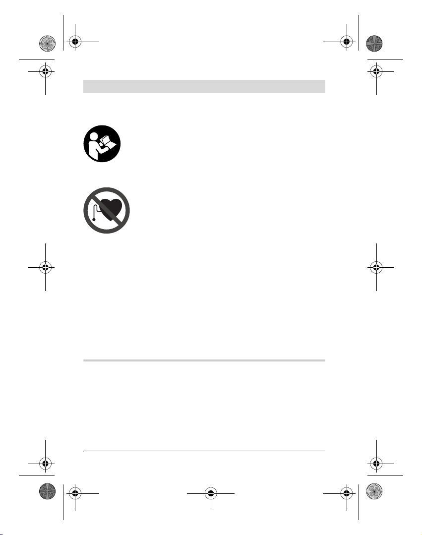
Optimales Arbeiten mit dem Messwerkzeug ist nur
möglich, wenn Sie die Bedienungsanleitung und die
Arbeitshinweise vollständig lesen und die darin
enthaltenen Anweisungen strikt befolgen. BEWAHREN SIE DIESE ANWEISUNGEN GUT AUF.
Bringen Sie das Messwerkzeug nicht in die Nähe
von Herzschrittmachern. Durch die Magnetplatte 12
wird ein Feld erzeugt, das die Funktion von Herzschrittmachern beeinträchtigen kann.
f Halten Sie das Messwerkzeug fern von magnetischen Daten-
trägern und magnetisch empfindlichen Geräten. Durch die
Wirkung der Magnetplatte 12 kann es zu irreversiblen Datenverlusten kommen.
Funktionsbeschreibung
Bitte klappen Sie die Ausklappseite mit der Darstellung des Messwerkzeugs auf, und lassen Sie diese Seite aufgeklappt, während
Sie die Bedienungsanleitung lesen.
Bestimmungsgemäßer Gebrauch
Das Messwerkzeug ist bestimmt zum schnellen Finden von rotierenden Laserstrahlen.
1 609 929 L81 | (20.7.07) Bosch Power Tools
Page 7
OBJ_BUCH-71-002.book Page 7 Friday, July 20, 2007 10:07 AM
Deutsch | 7
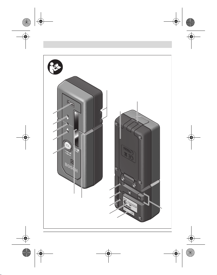
Abgebildete Komponenten
Die Nummerierung der abgebildeten Komponenten bezieht sich
auf die Darstellung des Messwerkzeugs auf der Grafikseite.
1 Libelle
2 Richtungsanzeige oben
3 Mittenanzeige
4 Richtungsanzeige unten
5 Ein-Aus-Taste/Tonsignaltaste
6 Empfangsfeld für Laserstrahl
7 Mittenmarkierung
8 Aufnahme für Halterung
9 Arretierung des Batteriefachdeckels
10 Batteriefachdeckel
11 Seriennummer
12 Magnetplatte
13 Arretierung der Halterung
14 Halterung
15 Obere Kante der Halterung
16 Baulaser-Messlatte*
17 Feststellschraube der Halterung
*Abgebildetes oder beschriebenes Zubehör gehört nicht zum StandardLieferumfang.
Geräuschinformation
Der A-bewertete Schalldruckpegel des Signaltons beträgt in einem
Meter Abstand 87 dB(A).
Halten Sie das Messwerkzeug nicht dicht ans Ohr!
Bosch Power Tools 1 609 929 L81 | (20.7.07)
Page 8

OBJ_BUCH-71-002.book Page 8 Friday, July 20, 2007 10:07 AM
8 | Deutsch
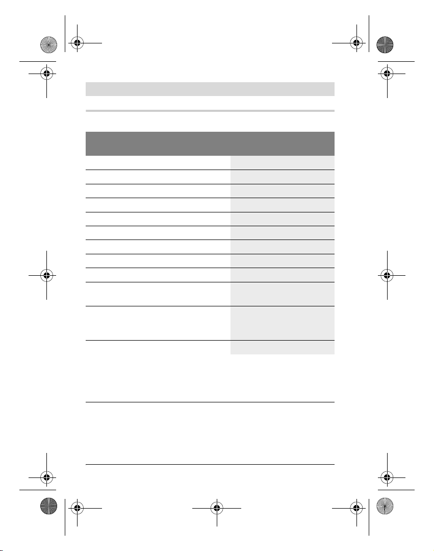
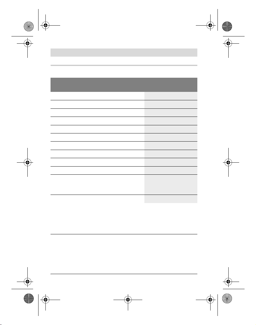
Technische Daten
Hochleistungsempfänger BLE 200
Professional
Sachnummer
Arbeitsbereich*
Empfangswinkel
Empfangbare Rotationsgeschwindigkeit
3 601 K17 101
200 m
120°
>200 min
Messgenauigkeit 3mm
Betriebstemperatur
Lagertemperatur
Batterien
Betriebsdauer ca.
– 10 °C ... +50 °C
– 20 °C ... +70 °C
2x1,5V AA (LR6)
70 h
Gewicht entsprechend
EPTA-Procedure 01/2003
Schutzart
IP 66 (staubdicht
0,2 kg
und strahlwasser-
geschützt)
Maße
* Der Arbeitsbereich kann durch ungünstige Umgebungsbedingungen
(z.B. direkte Sonneneinstrahlung) verringert werden.
Bitte beachten Sie die Sachnummer auf dem Typenschild Ihres Messwerkzeugs, die Handelsbezeichnungen einzelner Messwerkzeuge können variieren.
135 x 50 x 32 mm
Zur eindeutigen Identifizierung Ihres Messwerkzeugs dient die Seriennummer 11 auf dem Typenschild.
-1
1 609 929 L81 | (20.7.07) Bosch Power Tools
Page 9

OBJ_BUCH-71-002.book Page 9 Friday, July 20, 2007 10:07 AM
Deutsch | 9
Montage
Batterien einsetzen/wechseln
Verwenden Sie ausschließlich Alkali-Mangan-Batterien.
Drücken Sie die Arretierung 9 des Batteriefachs mit einem geeigne-
ten Werkzeug nach außen und klappen Sie den Batteriefachdeckel
10 auf.
Achten Sie beim Einsetzen der Batterien auf die richtige Polung
entsprechend der Abbildung im Batteriefach.
Blinken die Richtungsanzeigen 4 und 2 abwechselnd, müssen die
Batterien gewechselt werden.
Ersetzen Sie immer alle Batterien gleichzeitig. Verwenden Sie nur
Batterien eines Herstellers und mit gleicher Kapazität.
f Nehmen Sie die Batterien aus dem Messwerkzeug, wenn Sie
es längere Zeit nicht benutzen. Die Batterien können bei länge-
rer Lagerung korrodieren und sich selbst entladen.
Betrieb
Inbetriebnahme
f Setzen Sie das Messwerkzeug keinen extremen Temperatu-
ren oder Temperaturschwankungen aus. Lassen Sie es z.B.
nicht längere Zeit im Auto liegen. Lassen Sie das Messwerkzeug
bei größeren Temperaturschwankungen erst austemperieren,
bevor Sie es in Betrieb nehmen.
Stellen Sie das Messwerkzeug mindestens 50 cm vom Baulaser
entfernt auf. Platzieren Sie es so, dass der Laserstrahl das Empfangsfeld 6 erreichen kann. Stellen Sie am Baulaser die höchste Rotationsgeschwindigkeit ein.
Bosch Power Tools 1 609 929 L81 | (20.7.07)
Page 10

OBJ_BUCH-71-002.book Page 10 Friday, July 20, 2007 10:07 AM
10 | Deutsch
Ein-/Ausschalten
f Beim Einschalten des Messwerkzeugs ertönt ein lauter Signal-
ton. Halten Sie deshalb das Messwerkzeug beim Einschalten
vom Ohr bzw. von anderen Personen fern. Der laute Ton kann
das Gehör schädigen.
Drücken Sie zum Einschalten des Messwerkzeugs kurz die Taste 5
(„<1 sec on“). Die Richtungsanzeigen 4, 3 und 2 auf Vorder- und
Rückseite des Messwerkzeugs leuchten für eine Sekunde, und ein
kurzes Tonsignal ertönt.
Zur Anzeige der Betriebsbereitschaft leuchtet bei eingeschaltetem
Empfänger die Mittenanzeige 3 alle 2 Sekunden auf. Sobald der Laserstrahl das Empfangsfeld 6 durchläuft, zeigen die Richtungsanzeigen 4, 3 und 2 ausschließlich die Höhe des Laserstrahls an (siehe „Richtungsanzeigen“, Seite 10).
Drücken Sie zum Ausschalten des Messwerkzeugs die Taste 5 länger als eine Sekunde („>1 sec off“). Das Ausschalten wird vom
Messwerkzeug mit dem Aufleuchten der drei Richtungsanzeigen 4,
3 und 2 angezeigt, und ein kurzes Tonsignal ertönt.
Wird ca. 30 min keine Taste am Messwerkzeug gedrückt und erreicht das Empfangsfeld 6 30 min lang kein Laserstrahl, dann
schaltet das Messwerkzeug zur Schonung der Batterien automatisch ab.
Richtungsanzeigen
Die Anzeigen unten 4, Mitte 3 und oben 2 (jeweils auf Vorder- und
Rückseite des Messwerkzeugs) sowie der Signalton zeigen die Position des umlaufenden Laserstrahls im Empfangsfeld 6 an.
Durchläuft der Laserstrahl erstmals das Empfangsfeld 6, dann ertönt auch bei abgeschaltetem Signalton ein einmaliges Signal.
1 609 929 L81 | (20.7.07) Bosch Power Tools
Page 11
OBJ_BUCH-71-002.book Page 11 Friday, July 20, 2007 10:07 AM
Deutsch | 11
Laserstrahl zu hoch: Durchläuft der Laserstrahl die obere Hälfte
des Empfangsfeldes 6, dann blinkt die untere Richtungsanzeige 4.
Bei eingeschaltetem Signalton ertönt ein Signal in langsamem
Takt. Bewegen Sie das Messwerkzeug in Pfeilrichtung nach oben.
Laserstrahl zu tief: Durchläuft der Laserstrahl die untere Hälfte
des Empfangsfeldes 6, dann blinkt die obere Richtungsanzeige 2.
Bei eingeschaltetem Signalton ertönt ein Signal in schnellem Takt.
Bewegen Sie das Messwerkzeug in Pfeilrichtung nach unten.
Laserstrahl mittig: Durchläuft der Laserstrahl das Empfangsfeld 6
auf Höhe der Mittenmarkierung 7, dann blinkt die Mittenanzeige 3.
Bei eingeschaltetem Signalton ertönt ein Dauerton.
Signalton
Sie können den Signalton ein- und ausschalten. Drücken Sie dazu
die Taste 5 einmal kurz („<1 sec“).
Beim Ein- und Ausschalten des Signaltones leuchten jeweils die
Richtungsanzeigen 4, 3 und 2 kurz. Beim Einschalten ertönen drei
Signaltöne, beim Ausschalten ein einzelner Signalton.
Durchläuft der Laserstrahl erstmals das Empfangsfeld 6, dann ertönt auch bei abgeschaltetem Signalton ein einmaliges Signal.
Nach Einschalten des Messwerkzeugs ist der Signalton immer eingeschaltet.
Arbeitshinweise
Markieren
An der Mittenmarkierung 7 rechts und links am Messwerkzeug können Sie die Höhe des Laserstrahls markieren, wenn er durch die
Mitte des Empfangsfeldes 6 läuft. Die Mittenmarkierung befindet
sich 50 mm von der oberen Kante des Messwerkzeugs entfernt.
Bosch Power Tools 1 609 929 L81 | (20.7.07)
Page 12

OBJ_BUCH-71-002.book Page 12 Friday, July 20, 2007 10:07 AM
12 | Deutsch
Ausrichten mit der Libelle
Mit Hilfe der Libelle 1 können Sie das Messwerkzeug senkrecht
(lotrecht) ausrichten. Ein schief angebrachtes Messwerkzeug führt
zu Fehlmessungen.
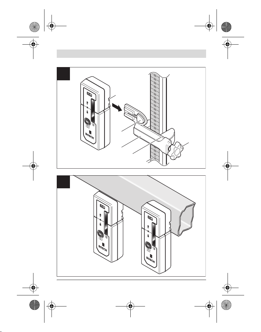
Befestigen mit Halterung (siehe Bild A)
Sie können das Messwerkzeug mit Hilfe der Halterung 14 sowohl
an einer Baulaser-Messlatte 16 (Zubehör) als auch an anderen
Hilfsmitteln mit einer Breite von ca. 5 bis 50 mm befestigen.
Schieben Sie die Halterung 14 seitlich bis zum hörbaren Einrasten
in die Aufnahme 8 an der Rückseite des Messwerkzeugs.
Lösen Sie die Feststellschraube 17, schieben Sie die Halterung z.B.
auf die Baulaser-Messlatte 16 und ziehen Sie die Feststellschraube
17 wieder fest.
Die obere Kante 15 der Halterung befindet sich auf der gleichen
Höhe wie die Mittenmarkierung 7 und kann zum Markieren des Laserstrahls verwendet werden.
Zum Entnehmen des Messwerkzeugs aus der Halterung 14 drücken
Sie die Arretierung 13 und ziehen das Messwerkzeug aus der Halterung.
Befestigen mit Magnet (siehe Bild B)
Ist eine sichere Befestigung nicht unbedingt erforderlich, können
Sie das Messwerkzeug mit Hilfe der Magnetplatte 12 stirn- und
rückseitig an Stahlteile heften.
1 609 929 L81 | (20.7.07) Bosch Power Tools
Page 13
OBJ_BUCH-71-002.book Page 13 Friday, July 20, 2007 10:07 AM
Deutsch | 13
Wartung und Service
Wartung und Reinigung
Halten Sie das Messwerkzeug stets sauber.
Wischen Sie Verschmutzungen mit einem trockenen, weichen Tuch
ab. Verwenden Sie keine Reinigungs- oder Lösemittel.
Sollte das Messwerkzeug trotz sorgfältiger Herstellungs- und Prüf-
verfahren einmal ausfallen, ist die Reparatur von einer autorisierten Kundendienststelle für Bosch-Elektrowerkzeuge ausführen zu
lassen.
Geben Sie bei allen Rückfragen und Ersatzteilbestellungen bitte
unbedingt die 10-stellige Sachnummer laut Typenschild des Messwerkzeugs an.
Ersatzteile
Batteriefachdeckel 10 mit Schrauben. . . . . . . . . . . 1 609 203 W30
Halterung . . . . . . . . . . . . . . . . . . . . . . . . . . . . . . . . 1 609 203 W31
Kundendienst und Kundenberatung
Der Kundendienst beantwortet Ihre Fragen zu Reparatur und Wartung Ihres Produkts sowie zu Ersatzteilen. Explosionszeichnungen
und Informationen zu Ersatzteilen finden Sie auch unter:
www.bosch-pt.com
Das Bosch-Kundenberater-Team hilft Ihnen gerne bei Fragen zu
Kauf, Anwendung und Einstellung von Produkten und Zubehören.
www.powertool-portal.de, das Internetportal für Handwerker und
Heimwerker.
www.ewbc.de, der Informations-Pool für Handwerk und Ausbildung.
Bosch Power Tools 1 609 929 L81 | (20.7.07)
Page 14

OBJ_BUCH-71-002.book Page 14 Friday, July 20, 2007 10:07 AM
14 | Deutsch
Deutschland
Robert Bosch GmbH
Servicezentrum Elektrowerkzeuge
Zur Luhne 2
37589 Kalefeld – Willershausen
Tel. Kundendienst: +49 (1805) 70 74 10
Fax: +49 (1805) 70 74 11
E-Mail: Servicezentrum.Elektrowerkzeuge@de.bosch.com
Tel. Kundenberatung: +49 (1803) 33 57 99
Fax: +49 (711) 7 58 19 30
E-Mail: kundenberatung.ew@de.bosch.com
Österreich
ABE Service GmbH
Jochen-Rindt-Straße 1
1232 Wien
Tel. Service: +43 (01) 61 03 80
Fax: +43 (01) 61 03 84 91
Tel. Kundenberater: +43 (01) 7 97 22 30 66
E-Mail: abe@abe-service.co.at
Schweiz
Tel.: +41 (044) 8 47 15 11
Fax: +41 (044) 8 47 15 51
Luxemburg
Tel.: +32 (070) 22 55 65
Fax: +32 (070) 22 55 75
E-Mail: outillage.gereedschap@be.bosch.com
1 609 929 L81 | (20.7.07) Bosch Power Tools
Page 15
OBJ_BUCH-71-002.book Page 15 Friday, July 20, 2007 10:07 AM
Deutsch | 15
Entsorgung
Messwerkzeuge, Zubehör und Verpackungen sollen einer umweltgerechten Wiederverwertung zugeführt werden.
Nur für EU-Länder:
Werfen Sie Messwerkzeuge nicht in den Hausmüll!
Gemäß der Europäischen Richtlinie 2002/96/EG
über Elektro- und Elektronik-Altgeräte und ihrer Umsetzung in nationales Recht müssen nicht mehr gebrauchsfähige Messwerkzeuge getrennt gesammelt
und einer umweltgerechten Wiederverwertung zugeführt werden.
Akkus/Batterien:
Werfen Sie Akkus/Batterien nicht in den Hausmüll, ins Feuer oder
ins Wasser. Akkus/Batterien sollen gesammelt, recycelt oder auf
umweltfreundliche Weise entsorgt werden.
Nur für EU-Länder:
Gemäß der Richtlinie 91/157/EWG müssen defekte oder verbrauchte Akkus/Batterien recycelt werden.
Nicht mehr gebrauchsfähige Akkus/Batterien können direkt abgegeben werden bei:
Deutschland
Recyclingzentrum Elektrowerkzeuge
Osteroder Landstraße 3
37589 Kalefeld
Schweiz
Batrec AG
3752 Wimmis BE
Änderungen vorbehalten.
Bosch Power Tools 1 609 929 L81 | (20.7.07)
Page 16
OBJ_BUCH-71-002.book Page 16 Friday, July 20, 2007 10:07 AM
16 | English
en
Safety Rules
Optimal working with the measuring tool is possible only when the operating instructions and information are read completely, and the instructions
contained therein are strictly followed. SAVE
THESE INSTRUCTIONS.
Keep the measuring tool away from cardiac pacemakers. The magnet plate 12 generates a field that
can impair the function of cardiac pacemakers.
f Keep the measuring tool away from magnetic data medium
and magnetically-sensitive equipment. The effect of the mag-
net plate 12 can lead to irreversible data loss.
Functional Description
Please unfold the fold-out page with the representation of the
measuring tool and leave it unfolded while reading the operating
instructions.
Intended Use
The measuring tool is intended for quick finding of rotating laser
beams.
1 609 929 L81 | (20.7.07) Bosch Power Tools
Page 17
OBJ_BUCH-71-002.book Page 17 Friday, July 20, 2007 10:07 AM
English | 17
Product Features
The numbering of the product features shown refers to the illustration of the measuring tool on the graphic page.
1 Spirit level
2 “Top” direction indicator
3 Centre indicator
4 “Bottom” direction indicator
5 On/Off and tone signal push button
6 Reception area for the laser beam
7 Centre mark
8 Retainer openings for holder
9 Latch of battery lid
10 Battery lid
11 Serial number
12 Magnet plate
13 Holder latch
14 Holder
15 Holder upper edge
16 Construction laser measuring rod*
17 Locking screw for holding device
*The accessories illustrated or described are not included as standard delivery.
Noise Information
The A-weighted sound pressure level of the audio signal at one meter distance is 87 dB(A).
Do not hold the measuring tool close to your ear!
Bosch Power Tools 1 609 929 L81 | (20.7.07)
Page 18
OBJ_BUCH-71-002.book Page 18 Friday, July 20, 2007 10:07 AM
18 | English
Technical Data
High-performance Receiver BLE 200
Professional
Article number
Working range*
Receiving angle
Receivable rotation speed
Measuring accuracy
Operating temperature
Storage temperature
Batteries
Operating life time, approx.
3 601 K17 101
200 m
120°
>200 rpm
3mm
– 10 °C ... +50 °C
– 20 °C ... +70 °C
2x1.5V AA (LR6)
70 h
Weight according to
EPTA-Procedure 01/2003
Degree of protection
IP 66 (dust-proof and
0.2 kg
protected against
powerful water jets)
Dimensions
* The working range can be decreased by unfavourable environmental
conditions (e.g. direct sun irradiation).
Please observe the article number on the type plate of your measuring tool.
The trade names of the individual measuring tools may vary.
135 x 50 x 32 mm
The measuring tool can be clearly identified with the serial number
11 on the type plate.
1 609 929 L81 | (20.7.07) Bosch Power Tools
Page 19

OBJ_BUCH-71-002.book Page 19 Friday, July 20, 2007 10:07 AM
English | 19
Assembly
Inserting/Replacing the Battery
Use only alkali-manganese batteries.
Press the latch 9 of the battery lid outward with a suitable tool and
open the battery lid 10.
When inserting batteries, pay attention to the correct polarity ac-
cording to the representation on the inside of the battery compartment.
When the direction indicators 4 and 2 flash alternately, the batteries must be replaced.
Always replace all batteries at the same time. Only use batteries
from one brand and with the identical capacity.
f Remove the batteries from the measuring tool when not using
it for extended periods. When storing for extended periods,
the batteries can corrode and discharge themselves.
Operation
Initial Operation
f Do not subject the measuring tool to extreme temperatures or
variations in temperature. As an example, do not leave it in ve-
hicles for longer periods. In case of large variations in temperature, allow the measuring tool to adjust to the ambient temperature before putting it into operation.
Position the measuring tool at least 50 cm away from the laser level
and in such a manner that the laser beam can reach the reception
area 6. Set the highest rotational speed on the laser level.
Bosch Power Tools 1 609 929 L81 | (20.7.07)
Page 20
OBJ_BUCH-71-002.book Page 20 Friday, July 20, 2007 10:07 AM
20 | English
Switching On and Off
f A loud audio signal sounds when switching on the measuring
tool. Therefore, keep the measuring tool away from your ear
or other person when switching on. The loud audio signal can
cause hearing defects.
For switching on the measuring tool, briefly press button 5
(“<1 sec on”). The direction indicators 4, 3 and 2 on the front and
rear side of the measuring tool light up for one second and a brief
audio signal sounds.
To indicate the operational readiness, the centre indicator 3 lights
up every 2 seconds when the receiver is switched on. As soon as
the laser beam runs through the reception area 6, the direction indicators 4, 3 and 2 indicate only the height of the laser beam (see
“Direction Indicators”, page 20).
To switch off the measuring tool, press button 5 for more than one
second (“>1 sec off”). The switching off of the measuring tool is indicated by the three direction indicators 4, 3 and 2 lighting up, and
a brief audio signal sounds.
When no pushbutton on the measuring tool is pressed for approx.
30 minutes and when no laser beam is impinged upon the reception area 6 for 30 minutes, the measuring tool switches off automatically to save the batteries.
Direction Indicators
The direction indicators for bottom 4, centre 3 and top 2 (on both
the front and rear side of the measuring tool) as well as the audio
signal indicate the position of the rotating laser beam in the reception area 6.
When the laser beam runs through the reception area 6 the first
time, a single tone is signalled, even when the audio signal is
switched off.
1 609 929 L81 | (20.7.07) Bosch Power Tools
Page 21

OBJ_BUCH-71-002.book Page 21 Friday, July 20, 2007 10:07 AM
English | 21
Laser beam too high: When the laser beam runs through the upper
half of the reception area 6, the direction “bottom” indicator 4
flashes. When the audio signal is switched on, a slow pulsing signal
sounds. In this case, move the measuring tool upward in the direction of the arrow.
Laser beam too low: When the laser beam runs through the lower
half of the reception area 6, the direction “top” indicator 2 flashes.
When the audio signal is switched on, a fast pulsing signal sounds.
In this case, move the measuring tool downward in the direction of
the arrow.
Laser beam centred: When the laser beam runs through the reception area 6 at the height of the centre mark 7, then the centre indicator 3 flashes. When the audio signal is switched on, a continuous
signal sounds.
Audio Signal
The audio signal can be switched on and off. For this, briefly press
pushbutton 5 once (“<1 sec”).
When the audio signal is switched on and off, the direction indicators 4, 3 and 2 light up briefly. When switching on, three audio signals sound; when switching off, a single audio signal sounds.
When the laser beam runs through the reception area 6 the first
time, a single tone is signalled, even when the audio signal is
switched off.
After the measuring tool has been switched on, the audio signal is
always switched on.
Bosch Power Tools 1 609 929 L81 | (20.7.07)
Page 22

OBJ_BUCH-71-002.book Page 22 Friday, July 20, 2007 10:07 AM
22 | English
Operating Instructions
Marking
The height of the laser beam can be marked at the centre mark 7
on the right and left of the measuring tool when it runs through the
centre of the reception area 6. The centre mark is 50 mm away
from the upper edge of the measuring tool.
Aligning with the Spirit Level
The measuring tool can be aligned vertically (plumb line) with the
spirit level 1. A measuring tool applied out-of-level leads to faulty
measurements.
Attaching with the Holder (see figure A)
With the holder 14, the measuring tool can be fastened to a construction laser measuring rod 16 (accessory) as well as to other
auxiliary tools with a width of approx. 5 to 50 mm.
Slide the holder 14 sidewards into the retainer openings 8 on the
rear side of the measuring tool until it can be heard to latch.
Loosen the locking screw 17, slide the holder onto the construction laser measuring rod 16, for example, and retighten the locking
screw 17.
The upper edge 15 of the holder is located at the same height as
the centre mark 7 and can be used for marking of the laser beam.
To remove the measuring tool from the holder 14, press the holder
latch 13 and pull the measuring tool out of the holder.
Attaching with the Magnet (see figure B)
When a positive-lock attachment is not absolutely required, the
measuring tool can be attached to steel parts via the face and rear
side using the magnet plate 12.
1 609 929 L81 | (20.7.07) Bosch Power Tools
Page 23

OBJ_BUCH-71-002.book Page 23 Friday, July 20, 2007 10:07 AM
English | 23
Maintenance and Service
Maintenance and Cleaning
Keep the measuring tool clean at all times.
Wipe away debris or contamination with a dry, soft cloth. Do not
use cleaning agents or solvents.
If the measuring tool should fail despite the care taken in manufac-
turing and testing procedures, repair should be carried out by an
authorized after-sales service centre for Bosch power tools.
In all correspondence and spare parts orders, please always include the 10-digit article number given on the type plate of the
measuring tool.
Spare Parts
Battery lid 10 with screws . . . . . . . . . . . . . . . . . . . 1 609 203 W30
Holder . . . . . . . . . . . . . . . . . . . . . . . . . . . . . . . . . . . 1 609 203 W31
After-sales service and customer assistance
Our after-sales service responds to your questions concerning maintenance and repair of your product as well as spare parts. Exploded
views and information on spare parts can also be found under:
www.bosch-pt.com
Our customer consultants answer your questions concerning best
buy, application and adjustment of products and accessories.
Bosch Power Tools 1 609 929 L81 | (20.7.07)
Page 24

OBJ_BUCH-71-002.book Page 24 Friday, July 20, 2007 10:07 AM
24 | English
Great Britain
Robert Bosch Ltd. (B.S.C.)
P.O. Box 98
Broadwater Park
North Orbital Road
Denham
Uxbridge
UB 9 5HJ
Tel. Service: +44 (0844) 736 0109
Fax: +44 (0844) 736 0146
E-Mail: SPT-Technical.de@de.bosch.com
Ireland
Origo Ltd.
Unit 23 Magna Drive
Magna Business Park
City West
Dublin 24
Tel. Service: +353 (01) 4 66 67 00
Fax: +353 (01) 4 66 68 88
Australia, New Zealand and Pacific Islands
Robert Bosch Australia Pty. Ltd.
Power Tools
Locked Bag 66
Clayton South VIC 3169
Customer Contact Center
Inside Australia:
Phone: +61 (01300) 307 044
Fax: + 61 (01300) 307 045
Inside New Zealand:
Phone: +64 (0800) 543 353
Fax: +64 (0800) 428 570
Outside AU and NZ:
Phone: +61 (03) 9541 5555
www.bosch.com.au
1 609 929 L81 | (20.7.07) Bosch Power Tools
Page 25
OBJ_BUCH-71-002.book Page 25 Friday, July 20, 2007 10:07 AM
English | 25
Disposal
Measuring tools, accessories and packaging should be sorted for
environmental-friendly recycling.
Only for EC countries:
Do not dispose of measuring tools into household
waste!
According the European Guideline 2002/96/EC for
Waste Electrical and Electronic Equipment and its implementation into national right, measuring tools that
are no longer usable must be collected separately and
disposed of in an environmentally correct manner.
Battery packs/batteries:
Do not dispose of battery packs/batteries into household waste,
fire or water. Battery packs/batteries should be collected, recycled
or disposed of in an environmental-friendly manner.
Only for EC countries:
Defective or dead out battery packs/batteries must be recycled according the guideline 91/157/EEC.
Batteries no longer suitable for use can be directly returned at:
Great Britain
Robert Bosch Ltd. (B.S.C.)
P.O. Box 98
Broadwater Park
North Orbital Road
Denham
Uxbridge
UB 9 5HJ
Tel. Service: +44 (0844) 736 0109
Fax: +44 (0844) 736 0146
E-Mail: SPT-Technical.de@de.bosch.com
Subject to change without notice.
Bosch Power Tools 1 609 929 L81 | (20.7.07)
Page 26
OBJ_BUCH-71-002.book Page 26 Friday, July 20, 2007 10:07 AM
26 | Français
fr
Consignes de sécurité
Un travail optimal avec cet appareil de mesure
n’est possible que si vous lisez complètement les
instructions d’utilisation et les instructions de travail et que vous respectiez strictement les indications qui y sont mentionnées. GARDER PRECIEUSEMENT CES INSTRUCTIONS DE SECURITE.
Ne pas mettre l’appareil de mesure dans la proximité de stimulateurs cardiaques. Les disques magné-
tiques 12 génèrent un champ qui peut entraver le
fonctionnement de stimulateurs cardiaques.
f Maintenir l’appareil de mesure éloigné des supports de don-
nées magnétiques et des appareils réagissant aux sources magnétiques. L’effet du disque magnétique 12 peut entraîner des
pertes de donnés irréversibles.
Description du fonctionnement
Dépliez le volet sur lequel l’appareil de mesure est représenté de
manière graphique. Laissez le volet déplié pendant la lecture de la
présente notice d’utilisation.
Utilisation conforme
L’appareil de mesure est conçu pour la détection rapide de faisceaux laser en rotation.
1 609 929 L81 | (20.7.07) Bosch Power Tools
Page 27
OBJ_BUCH-71-002.book Page 27 Friday, July 20, 2007 10:07 AM
Français | 27
Eléments de l’appareil
La numérotation des éléments de l’appareil se réfère à la représentation de l’appareil de mesure sur la page graphique.
1 Bulle d’air
2 Indicateur de direction vers le haut
3 Affichage central
4 Indicateur de direction vers le bas
5 Interrupteur Marche — Arrêt/touche signale sonore
6 Zone de réception pour faisceau laser
7 Repère central
8 Logement de la fixation
9 Blocage du couvercle du compartiment à piles
10 Couvercle du compartiment à piles
11 Numéro de série
12 Plaque aimantée
13 Blocage de la fixation
14 Fixation
15 Bord supérieur de la fixation
16 Platine de mesure du laser de chantier*
17 Vis de serrage de la fixation
*Les accessoires décrits ou montrés ne sont pas compris dans l’emballage
standard.
Informations concernant les bruits
La mesure réelle (A) du niveau de pression acoustique du signal sonore à un mètre de distance est de 87 dB(A).
Ne pas tenir l’appareil de mesure près de l’oreille !
Bosch Power Tools 1 609 929 L81 | (20.7.07)
Page 28
OBJ_BUCH-71-002.book Page 28 Friday, July 20, 2007 10:07 AM
28 | Français
Caractéristiques techniques
Récepteur performant BLE 200
Professional
N° d’article
Zone de travail*
Angle de réception
Vitesse de rotation recevable
Précision de mesure
Température de service
Température de stockage
Piles
Durée de service env.
Poids suivant EPTA-Procédure 01/2003
Type de protection
3 601 K17 101
200 m
120°
>200 tr/min
3mm
– 10 °C ... +50 °C
– 20 °C ... +70 °C
2x1,5V AA (LR6)
70 h
0,2 kg
IP 66 (étanche à la
poussière et aux
projections d’eau)
Dimensions
* La zone de travail peut, dans des conditions défavorables, être réduite
(par ex. exposition directe au soleil).
Faire attention au numéro d’article se trouvant sur la plaque signalétique
de l’appareil de mesure. Les désignations commerciales des différents appareils peuvent varier.
135 x 50 x 32 mm
Pour permettre une identification précise de votre appareil de mesure, le numéro de série 11 est marqué sur la plaque signalétique.
1 609 929 L81 | (20.7.07) Bosch Power Tools
Page 29

OBJ_BUCH-71-002.book Page 29 Friday, July 20, 2007 10:07 AM
Français | 29
Montage
Mise en place/changement des piles
N’utiliser que des piles alcalines au manganèse.
Pousser vers l’extérieur le blocage 9 du compartiment à piles au
moyen d’un outil approprié et relever le couvercle du compartiment à piles 10.
Veillez à mettre les piles dans le bon sens de la polarité selon la figure dans le compartiment à piles.
Si les indicateurs de direction 4 et 2 clignotent en alternant, c’est
qu’il faut changer les piles.
Toujours remplacer toutes les piles en même temps. N’utiliser que
des piles de la même marque avec la même capacité.
f Sortir les piles de l’appareil de mesure au cas où l’appareil ne
serait pas utilisé pour une période assez longue. En cas de
stockage long, les piles peuvent corroder et se décharger.
Fonctionnement
Mise en service
f Ne pas exposer l’appareil de mesure à des températures ex-
trêmes ou de forts changements de température. Ne pas le
laisser traîner longtemps dans la voiture p.ex. En cas d'importants changements de température, laisser l’appareil de mesure
prendre la température ambiante avant de le mettre en service.
Placer l’appareil de mesure à au moins 50 cm du laser de chantier.
Le placer de manière à ce que le faisceau laser puisse atteindre la
zone de réception 6. Régler le laser sur la vitesse de rotation la plus
élevée.
Bosch Power Tools 1 609 929 L81 | (20.7.07)
Page 30

OBJ_BUCH-71-002.book Page 30 Friday, July 20, 2007 10:07 AM
30 | Français
Mise en Marche/Arrêt
f Lors de la mise en marche de l’appareil de mesure, un fort si-
gnal sonore se fait entendre. Maintenir alors l’appareil de mesure à l’écart de l’oreille ou d’autres personnes lors de la mise
en marche. Le bruit fort peut provoquer des séquelles auditives.
Pour mettre en marche l’appareil de mesure, appuyer brièvement
sur la touche 5 (« <1 sec on »). Les indicateurs de direction 4, 3 et
2 se trouvant sur la face avant et sur le dos de l’appareil de mesure
s’allument pour une seconde et un court signal sonore se fait entendre.
Pour indiquer que l’appareil est prêt à fonctionner, l’affichage central 3 s’allume toutes les 2 secondes quand le récepteur est allumé. Dès que le faisceau laser traverse la zone de réception 6, les
indicateurs de direction 4, 3 et 2 indiquent exclusivement la hauteur du faisceau laser (voir « Affichages de direction », page 30).
Pour arrêter l’appareil de mesure, appuyer sur la touche 5 pendant
plus d’une seconde (« > 1 sec off »). Les trois indicateurs de direction 4, 3 et 2 s’allument, ce qui indique que l’appareil de mesure
est éteint, et un court signal sonore se fait entendre.
Si aucune touche n’est appuyée sur l’appareil de mesure pendant
env. 30 min. et si aucun faisceau laser n’atteint la zone de réception 6 pendant 30 min., l’appareil de mesure s’éteint automatiquement pour ménager les piles.
Affichages de direction
Les affichages en bas 4, au milieu 3 et en haut 2 (se trouvant sur la
face avant et sur le dos de l’appareil de mesure) ainsi que le signal
sonore indiquent la position du faisceau laser en mouvement sur la
zone de réception 6.
Si le faisceau laser passe la zone de réception 6 pour la première
fois, un signal se fait entendre une fois, même si le signal sonore
est éteint.
1 609 929 L81 | (20.7.07) Bosch Power Tools
Page 31

OBJ_BUCH-71-002.book Page 31 Friday, July 20, 2007 10:07 AM
Français | 31
Le faisceau laser est trop haut : si le faisceau laser traverse la par-
tie supérieure de la zone de réception 6, l’indicateur du bas 4 se
met à clignoter. Si le signal sonore est en service, un signal au rythme lent se fait entendre. Déplacer l’outil de mesure vers le haut en
direction de la flèche.
Le faisceau laser est trop bas : si le faisceau laser traverse la partie inférieure de la zone de réception 6, l’indicateur du haut 2 se
met à clignoter. Si le signal sonore est en service, un signal au rythme rapide se fait entendre. Déplacer l’outil de mesure vers le bas
en direction de la flèche.
Faisceau laser au milieu : si le faisceau laser traverse la zone de réception 6 à hauteur du marquage au milieu 7, l’indicateur central 3
s’allume. Si la fonction signal sonore est mise en marche, un signal
acoustique permanent se fait entendre.
Signal sonore
Vous pouvez mettre le signal sonore en service ou l’éteindre. Appuyer à cet effet une fois brièvement sur la touche 5 (« <1 sec »).
A la mise en ou hors service du signal sonore, les indicateurs de direction 4, 3 et 2 s’allument brièvement. Trois signaux sonores se
font entendre à la mise en service, un seul à la mise hors service.
Si le faisceau laser passe la zone de réception 6 pour la première
fois, un signal se fait entendre une fois, même si le signal sonore
est éteint.
Une fois l’appareil de mesure mis en marche, le signal sonore est
toujours mis en marche.
Bosch Power Tools 1 609 929 L81 | (20.7.07)
Page 32

OBJ_BUCH-71-002.book Page 32 Friday, July 20, 2007 10:07 AM
32 | Français
Instructions d’utilisation
Marquage
Sur le marquage central 7 se trouvant à gauche et à droite de l’ap-
pareil de mesure, vous pouvez marquer la hauteur du faisceau laser, quand il passe le centre de la zone de réception 6. Le marquage central se trouve à une distance de 50 mm du bord supérieur de
l’appareil de mesure.
Alignement au moyen de la bulle d’air
Il est possible d’aligner verticalement l’outil de mesure au moyen
de la bulle d’air 1. Un outil de mesure pas d’aplomb conduit à des
mesures erronées.
Montage avec fixation (voir figure A)
Il est possible de monter l’appareil de mesure à l’aide de la fixation
14 soit sur la platine de mesure du laser de chantier 16 (accessoire) soit sur d’autres auxiliaires d’une largeur de 5 à 50 mm environ.
Enfoncer la fixation 14 par le côté et jusqu’à son encliquetage audible dans le logement 8 se trouvant sur le dos de l’appareil de mesure.
Desserrer la vis de fixation 17, faites coulisser la fixation par ex. sur
la platine de mesure du laser de chantier 16 et resserrer la vis de
fixation 17.
Le bord supérieur 15 de la fixation se trouve sur le même niveau
que le marquage central 7 et peut être utilisé pour marque le faisceau laser.
Pour sortir l’appareil de mesure de la fixation 14, appuyer sur le
blocage 13 et retirer l’appareil de mesure de la fixation.
1 609 929 L81 | (20.7.07) Bosch Power Tools
Page 33

OBJ_BUCH-71-002.book Page 33 Friday, July 20, 2007 10:07 AM
Français | 33
Fixation par aimant (voir figure B)
Si une fixation sûre n’est pas absolument nécessaire, vous pouvez
fixer l’outil de mesure à l’aide de la plaque aimantée 12 par l’avant
ou par l’arrière à des pièces métalliques.
Entretien et service après-vente
Nettoyage et entretien
Maintenir l’appareil de mesure propre.
Nettoyer l’appareil à l’aide d’un torchon doux et sec. Ne pas utiliser
de détergents ou de solvants.
Si, malgré tous les soins apportés à la fabrication et au contrôle de
l’appareil de mesure, celui-ci devait avoir un défaut, la réparation
ne doit être confiée qu’à une station de service après-vente agréée
pour outillage Bosch.
Pour toute demande de renseignement ou commande de pièces de
rechange, nous préciser impérativement le numéro d’article à dix
chiffres de l’appareil de mesure indiqué sur la plaque signalétique.
Pièces de rechange
Couvercle du compartiment
à piles 10 avec vis . . . . . . . . . . . . . . . . . . . . . . . . . .1 609 203 W30
Fixation . . . . . . . . . . . . . . . . . . . . . . . . . . . . . . . . . . 1 609 203 W31
Bosch Power Tools 1 609 929 L81 | (20.7.07)
Page 34

OBJ_BUCH-71-002.book Page 34 Friday, July 20, 2007 10:07 AM
34 | Français
Service après-vente et assistance des clients
Notre service après-vente répond à vos questions concernant la réparation et l’entretien de votre produit et les pièces de rechange.
Vous trouverez des vues éclatées ainsi que des informations concernant les pièces de rechange également sous :
www.bosch-pt.com
Les conseillers techniques Bosch sont à votre disposition pour répondre à vos questions concernant l’achat, l’utilisation et le réglage de vos produits et leurs accessoires.
France
Robert Bosch (France) S.A.S.
Service Après-Vente Electroportatif
126, rue de Stalingrad
93705 DRANCY Cédex
Tel. : +33 (0143) 11 90 06
Fax : +33 (0143) 11 90 33
E-Mail :
sav.outillage-electroportatif@fr.bosch.com
N° Vert : +33 (0800) 05 50 51
www.bosch.fr
Belgique, Luxembourg
Tel. : +32 (070) 22 55 65
Fax : +32 (070) 22 55 75
E-Mail : outillage.gereedschap@be.bosch.com
Suisse
Tel. : +41 (044) 8 47 15 12
Fax : +41 (044) 8 47 15 52
1 609 929 L81 | (20.7.07) Bosch Power Tools
Page 35

OBJ_BUCH-71-002.book Page 35 Friday, July 20, 2007 10:07 AM
Français | 35
Elimination des déchets
Les appareils de mesure ainsi que leurs accessoires et emballages,
doivent pouvoir suivre chacun une voie de recyclage appropriée.
Seulement pour les pays de l’Union Européenne :
Ne pas jeter votre appareil de mesure avec les ordures ménagères !
Conformément à la directive européenne
2002/96/CE relative aux déchets d’équipements
électriques et électroniques et sa réalisation dans
ne peut plus se servir doivent être séparés et suivre une voie de recyclage appropriée.
Accus/piles :
Ne pas jeter les accu/piles dans les ordures ménagères, ni dans les
flammes ou l’eau. Les accus/piles doivent être collectés, recyclés
ou éliminés en conformité avec les réglementations se rapportant
à l’environnement.
Seulement pour les pays de l’Union Européenne :
Les accus/piles usés ou défectueux doivent être recyclés conformément à la directive 91/157/CEE.
Les accus/ piles dont on ne peut plus se servir peuvent être déposés directement auprès de :
Suisse
Batrec AG
3752 Wimmis BE
les lois nationales, les appareils de mesure dont on
Sous réserve de modifications.
Bosch Power Tools 1 609 929 L81 | (20.7.07)
Page 36

OBJ_BUCH-71-002.book Page 36 Friday, July 20, 2007 10:07 AM
36 | Español
es
Instrucciones de seguridad
Solamente podrá trabajar de forma óptima con el
aparato de medición si lee íntegramente las instrucciones de manejo y de operación, ateniéndose
estrictamente a las instrucciones allí comprendidas. GUARDE ESTAS INSTRUCCIONES EN UN LUGAR SEGURO.
No coloque el aparato de medición cerca de personas que utilicen un marcapasos. El campo que pro-
duce la base magnética 12 puede perturbar el funcionamiento de los marcapasos.
f Mantenga el aparato de medición alejado de soportes de da-
tos magnéticos y de aparatos sensibles a los campos magnéticos. La base magnética 12 puede provocar una pérdida de da-
tos irreversible.
Descripción del funcionamiento
Despliegue y mantenga abierta la solapa con la imagen del aparato
de medida mientras lee las instrucciones de manejo.
Utilización reglamentaria
El aparato de medida ha sido diseñado para detectar rápidamente
rayos láser en rotación.
1 609 929 L81 | (20.7.07) Bosch Power Tools
Page 37

OBJ_BUCH-71-002.book Page 37 Friday, July 20, 2007 10:07 AM
Español | 37
Componentes principales
La numeración de los componentes está referida a la imagen del
aparato de medición en la página ilustrada.
1 Nivel de burbuja
2 Indicador de dirección superior
3 Indicador del centro
4 Indicador de dirección inferior
5 Tecla de conexión/desconexión/tecla para señal acústica
6 Ventana receptora del rayo láser
7 Marca central
8 Alojamiento para el soporte
9 Enclavamiento de la tapa del alojamiento de la pila
10 Tapa del alojamiento de la pila
11 Número de serie
12 Base magnética
13 Botón de retención del soporte
14 Soporte
15 Canto superior del soporte
16 Escala de nivelación del láser de construcción*
17 Tornillo de fijación del soporte
*Los accesorios descritos e ilustrados no corresponden al material que se
adjunta de serie.
Información sobre el ruido
El nivel de presión sonora de la señal acústica evaluado con un filtro A a una distancia de un metro es de 87 dB(A).
¡No coloque el aparato de medida demasiado cerca de sus oídos!
Bosch Power Tools 1 609 929 L81 | (20.7.07)
Page 38

OBJ_BUCH-71-002.book Page 38 Friday, July 20, 2007 10:07 AM
38 | Español
Datos técnicos
Receptor de alto rendimiento BLE 200
Professional
Nº de artículo
Alcance*
Ángulo de recepción
Velocidad de rotación detectable
3 601 K17 101
200 m
120°
>200 min
Exactitud de medida 3mm
Temperatura de operación
Temperatura de almacenamiento
Pilas
Autonomía aprox.
Peso según EPTA-Procedure 01/2003
Grado de protección
– 10 °C ... +50 °C
– 20 °C ... +70 °C
2x1,5V AA (LR6)
70 h
0,2 kg
IP 66 (estanco contra
polvo y proyecciones
de agua)
Dimensiones
* El trabajo bajo unas condiciones ambientales desfavorables (p.ej. en caso de una exposición directa al sol) puede llegar a mermar el alcance del
aparato.
Preste atención al nº de artículo que figura en la placa de características
de su aparato de medida, ya que pueden variar las denominaciones comerciales en ciertos aparatos de medida.
135 x 50 x 32 mm
El número de serie 11 grabado en la placa de características permite identificar de forma unívoca el aparato de medida.
-1
1 609 929 L81 | (20.7.07) Bosch Power Tools
Page 39

OBJ_BUCH-71-002.book Page 39 Friday, July 20, 2007 10:07 AM
Español | 39
Montaje
Inserción y cambio de la pila
Usar exclusivamente pilas alcalinas-manganeso.
Presione hacia fuera el enclavamiento 9 del alojamiento de la pila
con una herramienta apropiada y abra la tapa 10.
Al insertar las pilas, respete la polaridad correcta mostrada en el
alojamiento de las mismas.
Si los indicadores de dirección 4 y 2 parpadeasen alternativamen-
te, es necesario sustituir las pilas.
Siempre sustituya todas las pilas al mismo tiempo. Utilice pilas del
mismo fabricante e igual capacidad.
f Saque las pilas del aparato de medida si pretende no utilizarlo
durante largo tiempo. Tras un tiempo de almacenaje prolonga-
do, las pilas se puede llegar a corroer y autodescargar.
Operación
Puesta en marcha
f No exponga el aparato de medida ni a temperaturas extremas
ni a cambios bruscos de temperatura. No lo deje, p.ej., en el
coche durante un largo tiempo. Si el aparato de medida a sido
sometido a un gran cambio de temperatura, antes de ponerlo en
servicio, esperar primero a que se atempere.
Coloque el aparato de medición a una distancia mínima de 50 cm
respecto al láser de construcción. Colóquelo de manera que el rayo
láser pueda incidir contra la ventana receptora 6. Ajuste en el láser
de construcción la velocidad de rotación máxima.
Bosch Power Tools 1 609 929 L81 | (20.7.07)
Page 40

OBJ_BUCH-71-002.book Page 40 Friday, July 20, 2007 10:07 AM
40 | Español
Conexión/desconexión
f Al conectar el aparato de medición se emite una fuerte señal
acústica. Por ello, al conectar el aparato de medición, manténgalo alejado de su oído o de otras personas. La fuerte señal
acústica puede causar daños auditivos.
Para conectar el aparato de medición pulse brevemente la tecla 5
(“<1 sec on”). Los indicadores de dirección 4, 3 y 2 en el frente y
dorso del aparato de medición se encienden durante un segundo,
y se emite brevemente una señal acústica.
Para indicar que el aparato está en disposición de funcionamiento,
el receptor conectado hace que el indicador del centro 3 se encienda cada 2 segundos. En el momento en que el rayo láser incida sobre la ventana receptora 6 los indicadores de dirección 4, 3 y 2 solamente muestran el nivel de altura del rayo láser (ver “Indicadores
de dirección”, página 40).
Para desconectar el aparato de medición pulse durante más de un
segundo la tecla 5 (“>1 sec off”). La desconexión del aparato de
medición se señaliza al encenderse los tres indicadores de dirección 4, 3 y 2, además de emitirse una breve señal acústica.
Si durante aprox. 30 min no se pulsa ninguna de las teclas del aparato de medida y si en la ventana receptora 6 no incide ningún rayo
láser en el transcurso de 30 min, el aparato de medida se desconecta entonces automáticamente para proteger las pilas.
Indicadores de dirección
Los indicadores inferior 4, central 3 y superior 2 (tanto en el frente
como al dorso del aparato), así como la señal acústica, indican la
posición de altura del láser en rotación en la ventana receptora 6.
Si el rayo láser incide por primera vez contra la ventana receptora
6, se emite una única vez una señal acústica, incluso estando ésta
desactivada.
1 609 929 L81 | (20.7.07) Bosch Power Tools
Page 41

OBJ_BUCH-71-002.book Page 41 Friday, July 20, 2007 10:07 AM
Español | 41
Rayo láser demasiado alto: Si el rayo láser incidiese contra la par-
te superior de la ventana receptora 6, parpadea entonces el indicador de dirección inferior 4. Si se hubiese activado la señal acústica
se emite un tono en lenta secuencia. Desplace el aparato de medición hacia arriba en dirección de la flecha.
Rayo láser demasiado bajo: Si el rayo láser incidiese contra la parte inferior de la ventana receptora 6, parpadea entonces el indicador de dirección superior 2. Si se hubiese activado la señal acústica se emite un tono en rápida secuencia. Desplace el aparato de
medición hacia abajo en dirección de la flecha.
Rayo láser centrado: Si el rayo láser incide contra la ventana receptora 6 a la altura de la marca central 7, parpadea entonces el
indicador del centro 3. Si estuviese activada la señal acústica se
emite un tono permanente.
Señal acústica
La señal acústica puede activarse y desactivarse. Para ello, pulse
brevemente la tecla 5 una sola vez (“<1 sec”).
Al conectar y desconectar la señal acústica se encienden brevemente los indicadores de dirección 4, 3 y 2. Al activarse se emiten
tres señales acústicas, y al desactivarse se emite una sola señal.
Si el rayo láser incide por primera vez contra la ventana receptora
6, se emite una única vez una señal acústica, incluso estando ésta
desactivada.
Al conectar el aparato de medición se encuentra activada siempre
la señal acústica.
Bosch Power Tools 1 609 929 L81 | (20.7.07)
Page 42

OBJ_BUCH-71-002.book Page 42 Friday, July 20, 2007 10:07 AM
42 | Español
Instrucciones para la operación
Marcado
La marca central 7 situada al lado derecho e izquierdo del aparato
de medida le permite trazar la posición del rayo láser al incidir éste
contra el centro de la ventana receptora 6. La marca central está situada 50 mm más abajo del canto superior del aparato de medida.
Nivelación con el nivel de burbuja
El nivel de burbuja 1 le permite colocar perpendicularmente (a plomo) el aparato de medición. La mediciones realizadas con un aparato de medida colocado inclinado son erróneas.
Fijación al soporte (ver figura A)
El soporte 14 le permite fijar el aparato de medida tanto a la escala
de nivelación del láser de construcción 16 (accesorio especial) como a otros medios auxiliares de una anchura aprox. entre 5 y 50 mm.
Inserte lateralmente el soporte 14 hasta enclavarlo en el alojamiento 8 situado al dorso del aparato de medición.
Afloje el tornillo de fijación 17, inserte el soporte, p.ej., en la escala
de nivelación 16 y apriete nuevamente el tornillo de fijación 17.
El canto superior 15 del soporte se encuentra a la misma altura de
la marca central 7 y puede emplearse por ello para marcar la posición del rayo láser.
Para retirar el aparato de medición del soporte 14 presione el botón de retención 13 y saque el aparato de medición del soporte.
Sujeción magnética (ver figura B)
Si el trabajo a realizar no exigiese que la sujeción del aparato de
medición sea demasiado firme, éste puede fijarse a piezas de acero
por su cara frontal y posterior con la base magnética 12.
1 609 929 L81 | (20.7.07) Bosch Power Tools
Page 43

OBJ_BUCH-71-002.book Page 43 Friday, July 20, 2007 10:07 AM
Español | 43
Mantenimiento y servicio
Mantenimiento y limpieza
Mantenga limpio siempre el aparato de medida.
Limpie el aparato con un paño seco y suave. No utilice agentes de
limpieza ni disolvente.
Si a pesar de los esmerados procesos de fabricación y control, el
aparato de medida llegase a averiarse, la reparación deberá encargarse a un taller de servicio autorizado para herramientas eléctricas Bosch.
Al realizar consultas o solicitar piezas de repuesto, es imprescindible indicar siempre el nº de artículo de 10 dígitos que figura en la
placa de características del aparato de medida.
Piezas de repuesto
Tapa del alojamiento
de las pilas 10 con tornillos . . . . . . . . . . . . . . . . . . 1 609 203 W30
Soporte . . . . . . . . . . . . . . . . . . . . . . . . . . . . . . . . . . 1 609 203 W31
Servicio técnico y atención al cliente
El servicio técnico le asesorará en las consultas que pueda Ud. tener sobre la reparación y mantenimiento de su producto, así como
sobre piezas de recambio. Los dibujos de despiece e informaciones sobre las piezas de recambio las podrá obtener también en internet bajo:
www.bosch-pt.com
Nuestro equipo de asesores técnicos le orientará gustosamente en
cuanto a la adquisición, aplicación y ajuste de los productos y accesorios.
Bosch Power Tools 1 609 929 L81 | (20.7.07)
Page 44

OBJ_BUCH-71-002.book Page 44 Friday, July 20, 2007 10:07 AM
44 | Español
España
Robert Bosch España, S.A.
Departamento de ventas
Herramientas Eléctricas
C/Hermanos García Noblejas, 19
28037 Madrid
Tel. Asesoramiento al cliente: +34 (0901) 11 66 97
Fax: +34 (091) 327 98 63
Venezuela
Robert Bosch S.A.
Final Calle Vargas. Edf. Centro Berimer P.B.
Boleita Norte
Caracas 107
Tel.: +58 (02) 207 45 11
México
Robert Bosch S.A. de C.V.
Tel. Interior: +52 (01) 800 627 1286
Tel. D.F.: +52 (01) 52 84 30 62
E-Mail: arturo.fernandez@mx.bosch.com
Argentina
Robert Bosch Argentina S.A.
Av. Córdoba 5160
C1414BAW Ciudad Autonoma de Buenos Aires
Atencion al Cliente
Tel.: +54 (0810) 555 2020
E-Mail: herramientas.bosch@ar.bosch.com
1 609 929 L81 | (20.7.07) Bosch Power Tools
Page 45

OBJ_BUCH-71-002.book Page 45 Friday, July 20, 2007 10:07 AM
Español | 45
Perú
Autorex Peruana S.A.
República de Panamá 4045,
Lima 34
Tel.: +51 (01) 475-5453
E-Mail: vhe@autorex.com.pe
Chile
EMASA S.A.
Irarrázaval 259 – Ñuñoa
Santiago
Tel.: +56 (02) 520 3100
E-Mail: emasa@emasa.cl
Eliminación
Recomendamos que los aparatos de medición, accesorios y embalajes sean sometidos a un proceso de recuperación que respete el
medio ambiente.
Sólo para los países de la UE:
¡No arroje los aparatos de medición a la basura!
Conforme a la Directriz Europea 2002/96/CE sobre
aparatos eléctricos y electrónicos inservibles, tras su
conversión en ley nacional, deberán acumularse por
separado los aparatos de medición para ser sometidos a un reciclaje ecológico.
Bosch Power Tools 1 609 929 L81 | (20.7.07)
Page 46

OBJ_BUCH-71-002.book Page 46 Friday, July 20, 2007 10:07 AM
46 | Español
Acumuladores/pilas:
No arroje los acumuladores/pilas a la basura, ni al fuego, ni al agua.
Los acumuladores/pilas deberán guardarse y reciclarse o eliminarse de manera ecológica.
Sólo para los países de la UE:
Conforme a la directriz 91/157/CEE deberán reciclarse los acumuladores/pilas defectuosos o agotados.
Los acumuladores/ pilas agotados pueden entregarse directamente a su distribuidor habitual de Bosch:
España
Servicio Central de Bosch
Servilotec, S.L.
Polig. Ind. II, 27
Cabanillas del Campo
Tel.: +34 9 01 11 66 97
Reservado el derecho de modificación.
1 609 929 L81 | (20.7.07) Bosch Power Tools
Page 47

OBJ_BUCH-71-002.book Page 47 Friday, July 20, 2007 10:07 AM
Português | 47
pt
Indicações de segurança
Só é possível trabalhar optimizadamente com o instrumento de medição se a instrução de serviço e as
indicações de trabalho forem lidas por completo e
se as instruções nelas contidas forem seguidas à
risca. GUARDE BEM ESTAS INSTRUÇÕES.
O instrumento de medição deve ser mantido afastado de estimuladores cardíacos. Com a placa mag-
nética 12 é produzido um campo magnético que pode prejudicar o funcionamento de estimuladores
cardíacos.
f Manter o instrumento de medição longe de suporte de dados
magnéticos e de aparelhos com sensibilidade magnética. O
efeito da placa magnética 12 pode provocar perdas de dados irreversíveis.
Descrição de funções
Abrir a página basculante contendo a apresentação do instrumento
de medição, e deixar esta página aberta enquanto estiver lendo a
instrução de serviço.
Utilização conforme as disposições
O instrumento de medição destina-se a encontrar rapidamente raios laser em rotação.
Bosch Power Tools 1 609 929 L81 | (20.7.07)
Page 48

OBJ_BUCH-71-002.book Page 48 Friday, July 20, 2007 10:07 AM
48 | Português
Componentes ilustrados
A numeração dos componentes ilustrados refere-se à apresentação do instrumento de medição na página de esquemas.
1 Nível de bolha
2 Indicador de direcção “em cima”
3 Indicador do centro
4 Indicador de direcção “em baixo”
5 Tecla de ligar e desligar/tecla de sinal acústico
6 Campo de recepção do raio laser
7 Marca central
8 Admissão para a fixação
9 Travamento da tampa do compartimento da pilha
10 Tampa do compartimento da pilha
11 Número de série
12 Placa magnética
13 Tranca do dispositivo de fixação
14 Dispositivo de fixação
15 Canto superior do dispositivo de fixação
16 Régua de medição do nível laser*
17 Parafuso de fixação do suporte
*Acessórios apresentados ou descritos não pertencem ao volume de fornecimento.
Informação sobre ruídos
O nível de pressão acústica, avaliado como A, do sinal acústico é
de 87 dB(A) para uma distância de um metro.
Não segurar o instrumento de medição rente às orelhas!
1 609 929 L81 | (20.7.07) Bosch Power Tools
Page 49

OBJ_BUCH-71-002.book Page 49 Friday, July 20, 2007 10:07 AM
Dados técnicos
Português | 49
Receptor de alta potência BLE 200
Professional
N° do produto
Zona de trabalho*
Ângulo de recepção
Velocidade de rotação receptível
3 601 K17 101
200 m
120°
>200 min
Precisão de medição 3mm
Temperatura de funcionamento
Temperatura de armazenamento
Pilhas
Duração de funcionamento de aprox.
Peso conforme EPTA-Procedure 01/2003
Tipo de protecção
– 10 °C ... +50 °C
– 20 °C ... +70 °C
2 x 1,5 V AA (LR6)
70 h
0,2 kg
IP 66 (vedado contra
pó e protegido con-
tra salpicos de água)
Dimensões
* A área de trabalho pode ser reduzida devido a condições ambientais
(p.ex. insolação directa) desfavoráveis.
Observe o número do produto sobre a placa de identificação do seu instrumento de medição, pois as designações comerciais dos diversos instrumentos de medição podem variar.
135 x 50 x 32 mm
O número de série 11 sobre a placa de características serve para a
identificação inequívoca do seu instrumento de medição.
-1
Bosch Power Tools 1 609 929 L81 | (20.7.07)
Page 50

OBJ_BUCH-71-002.book Page 50 Friday, July 20, 2007 10:07 AM
50 | Português
Montagem
Introduzir/substituir pilhas
Utilizar exclusivamente pilhas de mangano alcalino.
Premir o travamento 9 do compartimento das pilhas para fora com
uma ferramenta apropriada e abrir a tampa do compartimento das
pilhas 10.
Colocar as pilhas no compartimento, com os pólos na posição correcta, conforme indicado na figura do compartimento da pilha.
As pilhas devem ser substituídas quando os indicadores de direcção 4 e 2 piscarem alternadamente.
Sempre substituir todas as pilhas ao mesmo tempo. Só utilizar pilhas de uma marca e com a mesma capacidade.
f Retirar as pilhas do instrumento de medição, se não for utili-
zado por tempo prolongado. As pilhas podem corroer-se ou
descarregar-se no caso de um armazenamento prolongado.
Funcionamento
Colocação em funcionamento
f Não sujeitar o instrumento de medição à temperaturas extre-
mas nem à variações de temperatura. Não deixá-lo dentro de
um automóvel durante muito tempo. No caso de maiores variações de temperatura deverá deixar o instrumento de medição
alcançar a temperatura de funcionamento antes de colocá-lo
em funcionamento.
Posicionar o instrumento de medição a uma distância de no mínimo 50 cm do nível laser. Posicioná-lo de modo que o raio laser possa alcançar o campo de recepção 6. Ajustar no nível laser a máxima
velocidade de rotação.
1 609 929 L81 | (20.7.07) Bosch Power Tools
Page 51

OBJ_BUCH-71-002.book Page 51 Friday, July 20, 2007 10:07 AM
Português | 51
Ligar e desligar
f Ao ligar o instrumento de medição soa sinal acústico alto. Por-
tanto deverá manter o instrumento de medição afastado dos
seus ouvidos e dos das outras pessoas. O som alto pode dani-
ficar os ouvidos.
Para ligar o instrumento de medição, premir por instantes a tecla
5 (“<1 sec on”). Os indicadores de direcção 4, 3 e 2 no lado da frente e no lado de trás do instrumento de medição se iluminam durante um segundo e soa um breve sinal acústico.
Com o receptor ligado, a indicação central 3 pisca a cada
2 segundos, para indicar a prontidão de funcionamento. Logo que
o raio laser passar pelo campo de recepção 6, os indicadores de
direcção 4, 3 e 2 indicam exclusivamente a altura do raio laser (veja
“Indicações de direcção”, página 51).
Para desligar o instrumento de medição, deverá premir a tecla 5
por mais do que um segundo (“>1 sec off”). Quando o instrumento
de medição é desligado, os três indicadores de direcção 4, 3 e 2 se
acendem e soa um breve sinal acústico.
Se durante aprox. 30 minuto não for premida nenhuma tecla do
instrumento de medição e se nenhum raio laser alcançar a área de
recepção 6 durante 30 minuto, o instrumento de medição desligar-se-á automaticamente para poupar a pilha.
Indicações de direcção
Os indicadores “em baixo” 4, “no centro” 3 e “em cima” 2 (respec-
tivamente no lado da frente e no lado de trás do instrumento de
medição), assim como o sinal acústico, indicam a posição do raio
laser rotativo no campo de recepção 6.
Logo que o raio laser passar pela área de recepção 6, soará um sinal, mesmo se o sinal acústico estiver desligado.
Bosch Power Tools 1 609 929 L81 | (20.7.07)
Page 52

OBJ_BUCH-71-002.book Page 52 Friday, July 20, 2007 10:07 AM
52 | Português
Raio laser muito alto: Quando o raio laser percorre a metade su-
perior do campo de recepção 6, pisca o indicador de direcção inferior 4. Se o sinal acústico estiver ligado, soará um sinal em cadência lenta. Movimentar o instrumento de medição, para cima, no
sentido da seta.
Raio laser muito baixo: Quando o raio laser percorre a metade inferior do campo de recepção 6, pisca o indicador de direcção superior 2. Se o sinal acústico estiver ligado, soará um sinal em cadência rápida. Movimentar o instrumento de medição, para baixo,
no sentido da seta.
Raio laser central: Quando o raio laser percorre o campo de recepção 6 na altura da marcação central 7, pisca a indicação central 3.
Se o sinal acústico estiver ligado, soa um som contínuo.
Sinal acústico
É possível ligar e desligar o sinal acústico. Para tal, premir uma vez
a tecla 5 por instantes (“<1 sec”).
Ao ligar e desligar o sinal acústico, iluminam-se, por instantes, respectivamente os indicadores de direcção 4, 3 e 2. Ao ligar, soam
três sinais acústicos, ao desligar, só um sinal acústico.
Logo que o raio laser passar pela área de recepção 6, soará um sinal, mesmo se o sinal acústico estiver desligado.
O sinal acústico permanece ligado após ligar o instrumento de medição.
Indicações de trabalho
Marcar
Na direita e na esquerda da marca central 7 do instrumento de medição pode ser marcada a altura do raio laser, se este passar pelo
centro da área de recepção 6. A marca central encontra-se a uma
distância de 50 mm do canto superior do instrumento de medição.
1 609 929 L81 | (20.7.07) Bosch Power Tools
Page 53

OBJ_BUCH-71-002.book Page 53 Friday, July 20, 2007 10:07 AM
Português | 53
Alinhar o nível de bolha
Com o nível de bolha 1 é possível alinhar verticalmente o instrumento de medição (a prumo). Um instrumento aplicado de forma
desalinhada, leva a erros de medição.
Fixar com o dispositivo de fixação (veja figura A)
Com o dispositivo de fixação 14 é possível fixar o instrumento de
medição à régua de medição do nível laser 16 (acessório), assim
como com outros dispositivos que tenham uma largura de aprox. 5
a 50 mm.
Introduzir o dispositivo de fixação 14 pelo lado na admissão 8 que
se encontra no lado de trás do instrumento de medição, até escutar um nítido som de engate.
Soltar o parafuso de fixação 17, empurrar o dispositivo de fixação,
p.ex. sobre a régua de medição do nível laser 16 e reapertar o parafuso de fixação 17.
O canto superior 15 do dispositivo de fixação encontra-se na mesma altura que a marca central 7 e pode ser utilizada para marcar o
raio laser.
Para retirar o instrumento de medição do dispositivo de fixação 14,
deverá premir o travamento 13 e puxar o instrumento de medição
do dispositivo de fixação.
Fixar com íman (veja figura B)
Se não for necessária uma fixação segura, é possível fixar o lado da
frente e o lado de trás do instrumento de medição com a placa
magnética 12 a partes de aço.
Bosch Power Tools 1 609 929 L81 | (20.7.07)
Page 54

OBJ_BUCH-71-002.book Page 54 Friday, July 20, 2007 10:07 AM
54 | Português
Manutenção e serviço
Manutenção e limpeza
Manter o instrumento de medição sempre limpo.
Limpar sujidades com um pano seco e macio. Não utilizar produtos
de limpeza nem solventes.
Se o instrumento de medição falhar, apesar de cuidadosos proces-
sos de fabricação e de teste, a reparação deverá ser executada por
uma oficina de serviço autorizada para ferramentas eléctricas Bosch.
Para todas as questões e encomendas de peças sobressalentas é
imprescindível indicar o número de produto de 10 dígitos como
consta na placa de características do instrumento de medição.
Peças sobressalentes
Tampa do compartimento
das pilhas 10 com parafusos . . . . . . . . . . . . . . . . . 1 609 203 W30
Dispositivo de fixação. . . . . . . . . . . . . . . . . . . . . . . 1 609 203 W31
Serviço pós-venda e assistência ao cliente
O serviço pós-venda responde às suas perguntas a respeito de serviços de reparação e de manutenção do seu produto, assim como
das peças sobressalentes. Desenhos explodidos e informações sobre peças sobressalentes encontram-se em:
www.bosch-pt.com
A nossa equipa de consultores Bosch esclarecem com prazer todas
as suas dúvidas a respeito da compra, aplicação e ajuste dos produtos e acessórios.
1 609 929 L81 | (20.7.07) Bosch Power Tools
Page 55

OBJ_BUCH-71-002.book Page 55 Friday, July 20, 2007 10:07 AM
Português | 55
Portugal
Robert Bosch LDA
Avenida Infante D. Henrique
Lotes 2E – 3E
1800 Lisboa
Tel.: +351 (021) 8 50 00 00
Fax: +351 (021) 8 51 10 96
Brasil
Robert Bosch Ltda.
Caixa postal 1195
13065-900 Campinas
Tel.: +55 (0800) 70 45446
E-Mail: sac@bosch-sac.com.br
Eliminação
Instrumentos de medição, acessórios e embalagens devem ser enviados a uma reciclagem ecológica de matéria prima.
Apenas países da União Europeia:
Não deitar instrumentos de medição no lixo doméstico!
De acordo com a directiva européia 2002/96/CE para aparelhos eléctricos e electrónicos velhos, e com
as respectivas realizações nas leis nacionais, os ins-
utilização, devem ser enviados separadamente a uma reciclagem
ecológica.
trumentos de medição que não servem mais para a
Bosch Power Tools 1 609 929 L81 | (20.7.07)
Page 56

OBJ_BUCH-71-002.book Page 56 Friday, July 20, 2007 10:07 AM
56 | Português
Acumuladores/pilhas:
Acumuladores/pilhas não devem ser deitados no lixo doméstico,
nem no fogo nem na água. Acumuladores/pilhas devem ser recolhidos, reciclados ou eliminados de forma ecológica.
Apenas países da União Europeia:
Acumuladores e pilhas defeituosos ou gastos devem ser reciclados
conforme a directiva 91/157/CEE.
Sob reserva de alterações.
1 609 929 L81 | (20.7.07) Bosch Power Tools
Page 57

OBJ_BUCH-71-002.book Page 57 Friday, July 20, 2007 10:07 AM
Italiano | 57
it
Norme di sicurezza
E’ possibile lavorare con lo strumento di misura in
maniera ottimale soltanto dopo aver letto completamente le istruzioni per l’uso e le indicazioni operative e seguendo rigorosamente le istruzioni in esse contenute. CUSTODIRE ACCURATAMENTE LE
PRESENTI ISTRUZIONI.
Non portare lo strumento di misura in prossimità di
pace-maker. Tramite la piastra magnetica 12 viene
generato un campo che può pregiudicare il funzionamento di pace-maker.
f Tenere lo strumento di misura lontano da supporti magnetici
di dati e da apparecchi sensibili ai magneti. A causa dell’azio-
ne della piastra magnetica 12 possono verificarsi perdite irreversibili di dati.
Descrizione del funzionamento
Si prega di aprire il risvolto di copertina su cui si trova raffigurato
schematicamente lo strumento di misura e lasciarlo aperto mentre
si legge il manuale delle Istruzioni per l’uso.
Uso conforme alle norme
Lo strumento di misura è previsto per il rilevamento veloce di raggi
laser in rotazione.
Bosch Power Tools 1 609 929 L81 | (20.7.07)
Page 58

OBJ_BUCH-71-002.book Page 58 Friday, July 20, 2007 10:07 AM
58 | Italiano
Componenti illustrati
La numerazione dei componenti si riferisce all’illustrazione dello
strumento di misura che si trova sulla pagina con la rappresentazione grafica.
1 Livella
2 Spia di rilevazione: alto
3 Spia di rilevazione del punto medio
4 Spia di rilevazione: basso
5 Tasto di accensione/spegnimento/Tasto segnale acustico
6 Campo di ricezione del raggio laser
7 Marcatura del punto medio
8 Sede per il supporto
9 Bloccaggio del coperchio del vano batterie
10 Coperchio del vano batterie
11 Numero di serie
12 Piastra magnetica
13 Blocco del supporto
14 Supporto
15 Bordo superiore del supporto
16 Asta metrica telescopica per livella laser*
17 Vite per il fissaggio del supporto
*L’accessorio illustrato o descritto nelle istruzioni per l’uso non è compreso nella fornitura standard.
Informazione sulla rumorosità
Il livello di pressione acustica stimato A del segnale acustico ad un
metro di distanza ammonta a 87 dB(A).
Non tenere mai lo strumento di misura direttamente vicino
all'orecchio!
1 609 929 L81 | (20.7.07) Bosch Power Tools
Page 59

OBJ_BUCH-71-002.book Page 59 Friday, July 20, 2007 10:07 AM
Dati tecnici
Italiano | 59
Ricevitore ad alto rendimento BLE 200
Professional
Codice prodotto
Campo operativo*
Angolo di ricezione
Velocità di rotazione ricevibile
3 601 K17 101
200 m
120°
>200 min
Precisione di misura 3mm
Temperatura di esercizio
Temperatura di magazzino
Batterie
Autonomia ca.
– 10 °C ... +50 °C
– 20 °C ... +70 °C
2 x 1,5 V AA (LR6)
70 h
Peso in funzione della
EPTA-Procedure 01/2003
Tipo di protezione
IP 66 (a tenuta di polvere
0,2 kg
e protetto contro getti di
acqua)
Misure
* Il campo operativo può subire delle riduzioni dovute a sfavorevoli condizioni ambientali (p.es. esposizione diretta ai raggi solari).
Si prega di tener presente il codice prodotto applicato sulla targhetta di costruzione del Vostro strumento di misura perché le denominazioni commerciali di singoli strumenti di misura possono variare.
135 x 50 x 32 mm
Per un’inequivocabile identificazione del Vostro strumento di misura fate riferimento al numero di serie 11 riportato sulla targhetta di
costruzione.
-1
Bosch Power Tools 1 609 929 L81 | (20.7.07)
Page 60

OBJ_BUCH-71-002.book Page 60 Friday, July 20, 2007 10:07 AM
60 | Italiano
Montaggio
Applicazione/sostituzione delle batterie
Utilizzare esclusivamente batterie alcaline al manganese.
Con un attrezzo adatto premere verso l’esterno il bloccaggio 9 del
vano batterie ed aprire il coperchio del vano batterie 10.
Applicando le batterie, accertarsi che vengano inserite corretta-
mente secondo la rispettiva polarizzazione elettrica raffigurata nel
vano batterie.
Se le spie di rilevazione 4 e 2 lampeggiano alternandosi, sostituire
le batterie.
Sostituire sempre contemporaneamente tutte le batterie. Utilizzare esclusivamente batterie che siano di uno stesso produttore e
che abbiano la stessa capacità.
f In caso di non utilizzo per periodi di tempo molto lunghi,
estrarre le batterie dallo strumento di misura. In caso di peri-
odi di deposito molto lunghi, le batterie possono subire corrosioni oppure e si possono scaricare.
Uso
Messa in funzione
f Mai esporre lo strumento di misura a temperature oppure a
sbalzi di temperatura estremi. Per esempio, non lasciarlo a lun-
go all'interno di una macchina. In caso di maggiori sbalzi di temperatura, prima di metterlo in funzione si deve attendere che lo
strumento di misura si sia ristabilizzato sulla temperatura normale.
1 609 929 L81 | (20.7.07) Bosch Power Tools
Page 61

OBJ_BUCH-71-002.book Page 61 Friday, July 20, 2007 10:07 AM
Italiano | 61
Installare lo strumento di misura ad una distanza di almeno 50 cm
dalla livella laser. Posizionarlo in modo tale che il raggio laser possa
raggiungere il campo di ricezione 6. Impostare alla livella laser la
massima velocità di rotazione.
Accendere/spegnere
f All’accensione dello strumento di misura suona un forte se-
gnale acustico. Per questa ragione all’accensione tenere l’apparecchio di misura lontano dall’orecchio o da altre persone.
Il forte segnale acustico può danneggiare l’udito.
Per l’accensione premere brevemente il tasto 5 dello strumento di
misura («< 1 sec on»). Le spie di rilevazione 4, 3 e 2 sul lato anteriore e sul retro dello strumento di misura si illuminano per un secondo e suona un breve segnale acustico.
Per la visualizzazione del segnale di pronto esercizio, quando il ricevitore è acceso, l’indicatore del centro 3 si illumina brevemente
ogni 2 secondi. Non appena il raggio laser passa attraverso il campo
di ricezione 6, le spie di rilevazione 4, 3 e 2 indicano esclusivamente
l’altezza del raggio laser (vedere «Spie di rilevazione», pagina 61).
Per lo spegnimento premere il tasto 5 dello strumento di misura
per più di un secondo («> 1 sec off»). Lo spegnimento viene indicato dallo strumento di misura con l’accensione delle tre spie di rilevazione 4, 3 e 2 e suona un brese segnale acustico.
Se per ca. 30 min non si preme nessun tasto dello strumento di misura e per 30 min nessun raggio laser 6 raggiunge il campo di ricezione, lo strumento di misura si spegne automaticamente riducendo il consumo delle batterie.
Spie di rilevazione
L’indicatore basso 4, l’indicatore del centro 3 e l’indicatore alto 2
(sul lato anteriore e sul retro dello strumento di misura) nonché il
segnale acustico indicano la posizione del raggio laser rotante nel
campo di ricezione 6.
Bosch Power Tools 1 609 929 L81 | (20.7.07)
Page 62

OBJ_BUCH-71-002.book Page 62 Friday, July 20, 2007 10:07 AM
62 | Italiano
Quando il raggio laser attraversa per la prima volta il campo di ricezione 6 si emette un unico segnale acustico anche in caso di funzione di segnale acustico disattivata.
Raggio laser troppo alto: Quando il raggio laser passa attraverso
la metà superiore del campo di ricezione 6 lampeggia la spia di direzione inferiore 4. In caso di segnale acustico acceso viene emesso un segnale acustico a ritmo lento. Spostare lo strumento verso
l’alto in direzione della freccia.
Raggio laser troppo basso: Quando il raggio laser passa attraverso
la metà superiore del campo di ricezione 6, lampeggia la spia di direzione inferiore 2. In caso di segnale acustico acceso viene emesso un segnale acustico a ritmo veloce. Spostare lo strumento verso
il basso in direzione della freccia.
Raggio laser centrale: Quando il raggio laser passa attraverso il
campo di ricezione 6 all’altezza della marcatura del punto medio 7
lampeggia l’indicatore del punto medio 3. Con segnale acustico attivato suona un segnale acustico permanente.
Segnale acustico
È possibile attivare e disattivare il segnale acustico. A tal fine, premere il tasto 5 una volta brevemente («<1 sec»).
Attivando e disattivando il segnale acustico si illuminano brevemente le rispettive spie di rilevazione 4, 3 e 2. Attivando si emettono tre segnali acustici, disattivando si emette un singolo segnale
acustico.
Quando il raggio laser attraversa per la prima volta il campo di ricezione 6 si emette un unico segnale acustico anche in caso di funzione di segnale acustico disattivata.
All’accensione dello strumento di misura il segnale acustico è sempre attivato.
1 609 929 L81 | (20.7.07) Bosch Power Tools
Page 63

OBJ_BUCH-71-002.book Page 63 Friday, July 20, 2007 10:07 AM
Italiano | 63
Indicazioni operative
Marcatura
Alla marcatura del punto medio 7 al lato destro ed al lato sinistro
dello strumento di misura è possibile marcare l’altezza del raggio
laser quando questo passa per il centro del campo di ricezione 6.
La marcatura del punto medio si trova ad una dis-tanza di 50 mm
dallo spigolo superiore dello strumento di misura.
Allineamento tramite la livella
Tramite la livella 1 è possibile regolare lo strumento di misura in
posizione verticale (filo a piombo). Uno strumento di misura in posizione non conforme comporta errori di misurazione.
Fissaggio tramite supporto (vedi figura A)
Tramite il supporto 14 è possibile fissare lo strumento di misura sia
su un’asta metrica telescopica della livella laser 16 (accessorio opzionale) che su altre apparecchiature ausiliarie che abbiano una
larghezza di ca. 5 fino a 50 mm.
Spostare il supporto 14 lateralmente fino a quando scatta in posizione in modo percettibile nella sede 8 sul retro dello strumento di
misura.
Allentare la vite di fissaggio 17, spingere il supporto p.es. sull’asta
metrica telescopica della livella laser 16 ed avvitare di nuovo forte
la vite di fissaggio 17.
Il bordo superiore 15 del supporto si trova alla stessa altezza della
tacca relativa al punto medio 7 e può essere utilizzato per marcare
il raggio laser.
Per togliere lo strumento di misura dal supporto 14 premere il
blocco 13 ed estrarre lo strumento di misura dal supporto.
Bosch Power Tools 1 609 929 L81 | (20.7.07)
Page 64

OBJ_BUCH-71-002.book Page 64 Friday, July 20, 2007 10:07 AM
64 | Italiano
Fissaggio tramite magnete (vedi figura B)
Se un fissaggio sicuro non dovesse essere assolutamente indispensabile, è possibile applicare lo strumento di misura frontalmente e
posteriormente su componenti in acciaio utilizzando la piastra magnetica 12.
Manutenzione ed assistenza
Manutenzione e pulizia
Avere cura di tenere lo strumento di misura sempre pulito.
Pulire ogni tipo di sporcizia utilizzando un panno asciutto e morbi-
do. Non utilizzare mai prodotti detergenti e neppure solventi.
Se nonostante gli accurati procedimenti di produzione e di control-
lo lo strumento di misura dovesse guastarsi, la riparazione va fatta
effettuare da un punto di assistenza autorizzato per gli elettroutensili Bosch.
Per ogni tipo di richiesta o di ordinazione di pezzi di ricambio, è indispensabile comunicare sempre il codice prodotto a dieci cifre riportato sulla targhetta di fabbricazione dello strumento di misura.
Parti di ricambio
Coperchio del vano batterie 10 con viti . . . . . . . . . 1 609 203 W30
Supporto . . . . . . . . . . . . . . . . . . . . . . . . . . . . . . . . 1 609 203 W31
Servizio di assistenza ed assistenza clienti
Il servizio di assistenza risponde alle Vostre domande relative alla
riparazione ed alla manutenzione del Vostro prodotto nonché concernenti le parti di ricambio. Disegni in vista esplosa ed informazioni relative alle parti di ricambio sono consultabili anche sul sito:
www.bosch-pt.com
1 609 929 L81 | (20.7.07) Bosch Power Tools
Page 65

OBJ_BUCH-71-002.book Page 65 Friday, July 20, 2007 10:07 AM
Italiano | 65
Il team assistenza clienti Bosch è a Vostra disposizione per rispondere alle domande relative all’acquisto, impiego e regolazione di
apparecchi ed accessori.
Italia
Robert Bosch S.p.A.
Via Giovanni da Udine 15
20156 Milano
Tel.: +39 (02) 36 96 26 63
Fax: +39 (02) 36 96 26 62
Tel.: Filo diretto con Bosch: +39 (02) 36 96 23 14
www.Bosch.it
Svizzera
Tel.: +41 (044) 8 47 15 13
Fax: +41 (044) 8 47 15 53
Smaltimento
Avviare ad un riciclaggio rispettoso dell’ambiente gli imballaggi, gli
strumenti di misura e gli accessori dismessi.
Solo per i Paesi della CE:
Non gettare tra i rifiuti domestici gli strumenti di misura dismessi!
Conformemente alla norma della direttiva
2002/96/CE sui rifiuti di apparecchiature elettriche
ed elettroniche (RAEE) ed all’attuazione del recepi-
mento nel diritto nazionale, gli strumenti di misura
diventati inservibili devono essere raccolti separatamente ed essere inviati ad una riutilizzazione ecologica.
Bosch Power Tools 1 609 929 L81 | (20.7.07)
Page 66

OBJ_BUCH-71-002.book Page 66 Friday, July 20, 2007 10:07 AM
66 | Italiano
Batterie ricaricabili/Batterie:
Qualunque sia il tipo di batteria consumata, essa non deve essere
gettarla tra i rifiuti domestici, nel fuoco o nell’acqua. Ogni tipo di
batteria consumata deve essere messa da parte, riciclata oppure
smaltita rispettando rigorosamente le esigenze di protezione
dell’ambiente.
Solo per i Paesi della CE:
Ogni tipo di batteria difettosa oppure consumata deve essere riciclata secondo la direttiva CEE 91/157.
Le batterie ricaricabili/ le batterie non funzionanti potranno essere
consegnate direttamente presso:
Italia
Ecoelit
Viale Misurata 32
20146 Milano
Tel.: +39 02 / 4 23 68 63
Fax: +39 02 / 48 95 18 93
Svizzera
Batrec AG
3752 Wimmis BE
Con ogni riserva di modifiche tecniche.
1 609 929 L81 | (20.7.07) Bosch Power Tools
Page 67

OBJ_BUCH-71-002.book Page 67 Friday, July 20, 2007 10:07 AM
Nederlands | 67
nl
Veiligheidsvoorschriften
Met het meetgereedschap kunt u alleen optimaal
werken als u de gebruiksaanwijzing en de tips voor
de werkzaamheden volledig leest en u de daarin
aanwezige aanwijzingen strikt opvolgt. BEWAAR
DEZE AANWIJZINGEN GOED.
Breng het meetgereedschap niet in de buurt van
een pacemaker. De magneetplaat 12 brengt een veld
voort dat de functie van een pacemaker nadelig kan
beïnvloeden.
f Houd het meetgereedschap uit de buurt van magnetische ge-
gevensdragers en magnetisch gevoelige apparatuur. Door de
werking van de magneetplaat 12 kan onherroepelijk gegevensverlies optreden.
Functiebeschrijving
Vouw de uitvouwbare pagina met de afbeelding van het meetgereedschap open en laat deze pagina opengevouwen terwijl u de gebruiksaanwijzing leest.
Gebruik volgens bestemming
Het meetgereedschap is bestemd voor het snel vinden van roterende laserstralen.
Bosch Power Tools 1 609 929 L81 | (20.7.07)
Page 68

OBJ_BUCH-71-002.book Page 68 Friday, July 20, 2007 10:07 AM
68 | Nederlands
Afgebeelde componenten
De componenten zijn genummerd zoals op de afbeelding van het
meetgereedschap op de pagina met afbeeldingen.
1 Libel
2 Richtingindicatie boven
3 Middenindicatie
4 Richtingindicatie onder
5 Aan/uit-toets en geluidssignaaltoets
6 Ontvangstveld voor laserstraal
7 Middenmarkering
8 Opname voor houder
9 Vergrendeling van het batterijvakdeksel
10 Deksel van batterijvak
11 Serienummer
12 Magneetplaat
13 Vergrendeling van houder
14 Houder
15 Bovenkant van houder
16 Bouwlaser-meetlat*
17 Vastzetschroef van houder
* Niet elk afgebeeld en beschreven toebehoren wordt standaard meegeleverd.
Informatie over geluid
Het A-gewogen geluidsdrukniveau van het geluidssignaal bedraagt
op een meter afstand 87 dB(A).
Houd het meetgereedschap niet dicht bij uw oor.
1 609 929 L81 | (20.7.07) Bosch Power Tools
Page 69

OBJ_BUCH-71-002.book Page 69 Friday, July 20, 2007 10:07 AM
Nederlands | 69
Technische gegevens
Ontvanger met hoog vermogen BLE 200
Professional
Zaaknummer
Werkbereik*
Ontvangsthoek
Te ontvangen rotatiesnelheid
3 601 K17 101
200 m
120°
>200 min
Meetnauwkeurigheid 3mm
Bedrijfstemperatuur
Bewaartemperatuur
Batterijen
Gebruiksduur ca.
Gewicht volgens EPTA-Procedure 01/2003
Beschermingsklasse
– 10 °C ... +50 °C
– 20 °C ... +70 °C
2 x 1,5 V AA (LR6)
70 h
0,2 kg
IP 66 (stofdicht en
beschermd tegen
straalwater)
Afmetingen
* De reikwijdte kan afnemen door ongunstige omgevingsomstandigheden
(zoals fel zonlicht).
Let op het zaaknummer op het typeplaatje van het meetgereedschap. De
handelsbenamingen van afzonderlijke meetgereedschappen kunnen afwijken.
135 x 50 x 32 mm
Het serienummer 11 op het typeplaatje dient voor de eenduidige
identificatie van uw meetgereedschap.
-1
Bosch Power Tools 1 609 929 L81 | (20.7.07)
Page 70

OBJ_BUCH-71-002.book Page 70 Friday, July 20, 2007 10:07 AM
70 | Nederlands
Montage
Batterijen inzetten of vervangen
Gebruik uitsluitend alkali-mangaan-batterijen.
Duw de vergrendeling 9 van het batterijvak met een geschikt ge-
reedschap naar buiten en klap het batterijvakdeksel 10 open.
Let bij het inzetten van de batterijen op de juiste poolaansluitingen
overeenkomstig de afbeelding in het batterijvak.
Als de indicaties 4 en 2 afwisselend knipperen, moeten de batterij-
en worden vervangen.
Vervang altijd alle batterijen tegelijkertijd. Gebruik alleen batterijen
van één fabrikant en met dezelfde capaciteit.
f Neem de batterijen uit het meetgereedschap als u het langdu-
rig niet gebruikt. Als de batterijen lang worden bewaard, kun-
nen deze gaan roesten en leegraken.
Gebruik
Ingebruikneming
f Stel het meetgereedschap niet bloot aan extreme temperatu-
ren of temperatuurschommelingen. Laat het bijvoorbeeld niet
lange tijd in de auto liggen. Laat het meetgereedschap bij grote
temperatuurschommelingen eerst op de juiste temperatuur komen voordat u het in gebruik neemt.
Stel het meetgereedschap minstens 50 cm van de bouwlaser verwijderd op. Plaats het zo dat de laserstraal het ontvangstveld 6 kan
bereiken. Stel op de bouwlaser de hoogste rotatiesnelheid in.
1 609 929 L81 | (20.7.07) Bosch Power Tools
Page 71

OBJ_BUCH-71-002.book Page 71 Friday, July 20, 2007 10:07 AM
Nederlands | 71
In- en uitschakelen
f Bij het inschakelen van het meetgereedschap klinkt een luid
geluidssignaal. Houd daarom het meetgereedschap bij het inschakelen uit de buurt van het oor en van andere personen.
Het luide geluid kan het gehoor beschadigen.
Als u het meetgereedschap wilt inschakelen, drukt u kort op de
toets 5 („<1 sec on”). De richtingindicaties 4, 3 en 2 aan de vooren achterzijde van het meetgereedschap branden gedurende één
seconde en er klinkt een kort geluidssignaal.
Als de ontvanger aan staat, licht de middenindicatie 3 elke twee seconden op om aan te geven dat het apparaat stand-by is. Zodra de
laserstraal het ontvangstveld 6 doorloopt, geven de richtingindicaties 4, 3 en 2 uitsluitend de hoogte van de laserstraal aan (zie
„Richtingindicaties”, pagina 71).
Als u het meetgereedschap wilt uitschakelen, drukt u de toets 5
langer dan één seconde in („>1 sec off”). Het uitschakelen wordt
door het meetgereedschap aangegeven met het oplichten van de
drie richtingindicaties 4, 3 en 2, en er klinkt een kort geluidssignaal.
Als er ca. 30 minuten geen toets op het meetgereedschap wordt ingedrukt en het ontvangstveld 6 30 minuten lang niet door een la-
serstraal wordt bereikt, wordt het meetgereedschap automatisch
uitgeschakeld om de batterijen te ontzien.
Richtingindicaties
De indicaties onder 4, midden 3 en boven 2 (resp. aan de voor- en
achterzijde van het meetgereedschap) en het geluidssignaal geven
de positie van de roterende laserstraal in het ontvangstveld 6 aan.
Als de laserstraal het ontvangstveld 6 voor het eerst doorloopt,
klinkt een eenmalig signaal, ook als het geluidssignaal uitgeschakeld is.
Bosch Power Tools 1 609 929 L81 | (20.7.07)
Page 72

OBJ_BUCH-71-002.book Page 72 Friday, July 20, 2007 10:07 AM
72 | Nederlands
Laserstraal te hoog: Als de laserstraal de bovenste helft van het
ontvangstveld 6 doorloopt, knippert de onderste richtingindicatie
4. Als het geluidssignaal ingeschakeld is, klinkt er een signaal met
een langzaam ritme. Beweeg het meetgereedschap in de richting
van de pijl omhoog.
Laserstraal te laag: Als de laserstraal de onderste helft van het ontvangstveld 6 doorloopt, knippert de bovenste richtingindicatie 2.
Als het geluidssignaal ingeschakeld is, klinkt er een signaal met een
snel ritme. Beweeg het meetgereedschap in de richting van de pijl
omlaag.
Laserstraal in het midden: Als de laserstraal het ontvangstveld 6
ter hoogte van de middenmarkering 7 doorloopt, knippert de middenindicatie 3. Als het geluidssignaal is ingeschakeld, klinkt er een
aanhoudend geluidssignaal.
Geluidssignaal
U kunt het geluidssignaal in- en uitschakelen. Druk daarvoor eenmaal kort op de toets 5 („<1 sec”).
Bij het in- en uitschakelen van het geluidssignaal branden de richtingindicaties 4, 3 en 2 kort. Bij het inschakelen klinken drie geluidssignalen, bij het uitschakelen één signaal.
Als de laserstraal het ontvangstveld 6 voor het eerst doorloopt,
klinkt een eenmalig signaal, ook als het geluidssignaal uitgeschakeld is.
Na het inschakelen van het meetgereedschap is het geluidssignaal
altijd ingeschakeld.
1 609 929 L81 | (20.7.07) Bosch Power Tools
Page 73

OBJ_BUCH-71-002.book Page 73 Friday, July 20, 2007 10:07 AM
Nederlands | 73
Tips voor de werkzaamheden
Markeren
Bij de middenmarkering 7 rechts en links op het meetgereedschap
kunt u de hoogte van de laserstraal markeren als deze door het
midden van het ontvangstveld 6 loopt. De middenmarkering bevindt zich 50 mm van de bovenkant van het meetgereedschap.
Richten met de libel
Met de libel 1 kunt u het meetgereedschap verticaal (loodrecht)
richten. Scheef aanbrengen van het meetgereedschap leidt tot foutieve metingen.
Bevestigen met houder (zie afbeelding A)
U kunt het meetgereedschap met de houder 14 op een bouwlasermeetlat 16 (toebehoren) of op andere hulpmiddelen met een
breedte van ca. 5 tot 50 mm bevestigen.
Schuif de houder 14 zijwaarts tot deze hoorbaar vastklikt in de opname 8 aan de achterzijde van het meetgereedschap.
Draai de vastzetschroef 17 los, duw de houder bijvoorbeeld op de
bouwlaser-meetlat 16 en draai de vastzetschroef 17 weer vast.
De bovenrand 15 van de houder bevindt zich op dezelfde hoogte
als de middenmarkering 7 en kan worden gebruikt voor het markeren van de laserstraal.
Als u het meetgereedschap uit de houder 14 wilt verwijderen,
drukt u op de vergrendeling 13 en trekt u het meetgereedschap uit
de houder.
Bevestigen met magneet (zie afbeelding B)
Als een zekere bevestiging niet beslist noodzakelijk is, kunt u het
meetgereedschap met de magneetplaat 12 aan de voor- en achterzijde op stalen delen hechten.
Bosch Power Tools 1 609 929 L81 | (20.7.07)
Page 74

OBJ_BUCH-71-002.book Page 74 Friday, July 20, 2007 10:07 AM
74 | Nederlands
Onderhoud en service
Onderhoud en reiniging
Houd het meetgereedschap altijd schoon.
Verwijder vuil met een droge, zachte doek. Gebruik geen reini-
gings- of oplosmiddelen.
Mocht het meetgereedschap ondanks zorgvuldige fabricage- en
testmethoden toch defect raken, dient de reparatie te worden uitgevoerd door een erkende klantenservice voor Bosch elektrische
gereedschappen.
Vermeld bij vragen en bestellingen van vervangingsonderdelen altijd het uit tien cijfers bestaande zaaknummer volgens het typeplaatje van het meetgereedschap.
Vervangingsonderdelen
Batterijvakdeksel 10 met schroeven. . . . . . . . . . . . 1 609 203 W30
Houder . . . . . . . . . . . . . . . . . . . . . . . . . . . . . . . . . . 1 609 203 W31
Klantenservice en advies
Onze klantenservice beantwoordt uw vragen over reparatie en onderhoud van uw product en over vervangingsonderdelen. Explosietekeningen en informatie over vervangingsonderdelen vindt u ook op:
www.bosch-pt.com
De medewerkers van onze klantenservice adviseren u graag bij vragen over de aankoop, het gebruik en de instelling van producten en
toebehoren.
1 609 929 L81 | (20.7.07) Bosch Power Tools
Page 75

OBJ_BUCH-71-002.book Page 75 Friday, July 20, 2007 10:07 AM
Nederlands | 75
Nederland
Tel.: +31 (076) 579 54 54
Fax: +31 (076) 579 54 94
E-mail: gereedschappen@nl.bosch.com
België en Luxemburg
Tel.: +32 (070) 22 55 65
Fax: +32 (070) 22 55 75
E-mail: outillage.gereedschap@be.bosch.com
Afvalverwijdering
Meetgereedschappen, toebehoren en verpakkingen dienen op een
voor het milieu verantwoorde manier te worden hergebruikt.
Alleen voor landen van de EU:
Gooi meetgereedschappen niet bij het huisvuil.
Volgens de Europese richtlijn 2002/96/EG over elektrische en elektronische oude apparaten en de omzetting van de richtlijn in nationaal recht moeten niet
meer bruikbare meetgereedschappen apart worden
ingezameld en op een voor het milieu verantwoorde
wijze worden hergebruikt.
Accu’s en batterijen:
Gooi accu’s of batterijen niet bij het huisvuil en evenmin in het vuur
of het water. Accu’s en batterijen moeten worden ingezameld, gerecycled of op een voor het milieu verantwoorde wijze worden afgevoerd.
Alleen voor landen van de EU:
Volgens richtlijn 91/157/EEG moeten defecte of versleten accu’s
en batterijen worden gerecycled.
Wijzigingen voorbehouden.
Bosch Power Tools 1 609 929 L81 | (20.7.07)
Page 76

OBJ_BUCH-71-002.book Page 76 Friday, July 20, 2007 10:07 AM
76 | Dansk
da
Sikkerhedsinstrukser
Optimalt arbejde med måleværktøjet forudsætter,
at betjeningsvejledningen og arbejdsforskrifterne
læses helt igennem og anvisningerne overholdes,
før det tages i brug. DISSE INSTRUKSER BØR OPBEVARES TIL SENERE BRUG.
Måleværktøjet må ikke komme i nærheden af pacemakere. Magnetpladen 12 danner et felt, som kan
påvirke pacemakernes funktion.
f Hold måleværktøjet væk fra magnetiske databærere og mag-
netisk sarte maskiner. Magnetpladens virkning 12 kan føre til ir-
reversibelt datatab.
Funktionsbeskrivelse
Klap venligst foldesiden med illustration af måleværktøjet ud og lad
denne side være foldet ud, mens du læser betjeningsvejledningen.
Beregnet anvendelse
Måleværktøjet er beregnet til hurtigt at finde roterende laserstråler.
1 609 929 L81 | (20.7.07) Bosch Power Tools
Page 77

OBJ_BUCH-71-002.book Page 77 Friday, July 20, 2007 10:07 AM
Dansk | 77
Illustrerede komponenter
Nummereringen af de illustrerede komponenter refererer til illustrationen af måleværktøjet på illustrationssiden.
1 Libelle
2 Retningsindikator oppe
3 Midterindikator
4 Retningsindikator nede
5 Tænd-sluk-taste/lydsignaltaste
6 Modtagerfelt til laserstråle
7 Midtermarkering
8 Fordybning til holder
9 Låsning af låg til batterirum
10 Låg til batterirum
11 Serienummer
12 Magnetplade
13 Fastlåsning af holder
14 Holder
15 Øverstekant på holder
16 Baulaser-måleplade*
17 Stilleskrue til holder
*Tilbehør, som er illustreret eller beskrevet i betjeningsvejledningen, hører ikke til standard-leveringen.
Støjinformation
Det A-vægtede lydtrykniveau for signaltonen er i en meters afstand
87 dB(A).
Hold ikke måleværktøjet helt op mod øret!
Bosch Power Tools 1 609 929 L81 | (20.7.07)
Page 78

OBJ_BUCH-71-002.book Page 78 Friday, July 20, 2007 10:07 AM
78 | Dansk
Tekniske data
Højkapacitetsmodtager BLE 200
Professional
Typenummer
Arbejdsområde*
Modtagervinkel
Modtagelig rotationshastighed
3 601 K17 101
200 m
120°
>200 min
Målepræcision 3mm
Driftstemperatur
Opbevaringstemperatur
Batterier
Driftstid ca.
Vægt svarer til EPTA-Procedure 01/2003
Tæthedsgrad
– 10 °C ... +50 °C
– 20 °C ... +70 °C
2x1,5V AA (LR6)
70 h
0,2 kg
IP 66 (støv- og sprøjte-
vandsbeskyttet)
Mål
* Arbejdsområdet kan blive mindre, hvis forholdene er ufordelagtige (f.eks.
direkte solstråler).
Vær opmærksom på dit måleværktøjs typenummer (på typeskiltet), handelsbetegnelserne for de enkelte måleværktøjer kan variere.
135 x 50 x 32 mm
Dit måleværktøj identificeres entydigt vha. serienummeret 11 på
typeskiltet.
-1
1 609 929 L81 | (20.7.07) Bosch Power Tools
Page 79

OBJ_BUCH-71-002.book Page 79 Friday, July 20, 2007 10:07 AM
Dansk | 79
Montering
Isætning/udskiftning af batterier
Anvend kun alkali-mangan-batterier.
Tryk låsen 9 til batterirummet ud med et egnet værktøj og klap lå-
get til batterirummet 10 op.
Kontrollér at batteripolerne vender rigtigt, når batterierne lægges i
(se billede på batterirum).
Blinker retningslamperne 4 og 2 på skift, skal batterierne skiftes.
Skift altid alle batterier på en gang. Batterierne skal stamme fra
den samme fabrikant og have den samme kapacitet.
f Tag batterierne ud af måleværktøjet, hvis måleværktøjet ikke
skal bruges i længere tid. Batterierne kan korrodere og aflade
sig selv, hvis de bliver siddende i måleværktøjet i længere tid.
Drift
Ibrugtagning
f Udsæt ikke måleværktøjet for ekstreme temperaturer eller
temperatursvingninger. Lad dem f.eks. ikke ligge i bilen i læn-
gere tid. Sørg altid for, at måleværtøjet er tempereret ved større
temperatursvingninger, før det tages i brug.
Opstil måleværktøjet mindst 50 cm væk fra bygningslaseren. Placér den på en sådan måde, at laserstrålen kan nå modtagerfeltet 6.
Indstil den max. rotationshastighed på bygningslaseren.
Bosch Power Tools 1 609 929 L81 | (20.7.07)
Page 80

OBJ_BUCH-71-002.book Page 80 Friday, July 20, 2007 10:07 AM
80 | Dansk
Tænd/sluk
f Når måleværktøjet tændes, høres en høj signallyd. Hold der-
for måleværktøjet væk fra øret eller andre personer, når det
tændes. Den høje lyd kan beskadige hørelsen.
Måleværktøjet tændes ved kort at trykke på tasten 5 („<1 sec on“).
Retningslamperne 4, 3 og 2 på for- og bagsiden af måleværktøjet
lyser i et sekund, og der høres et kort signal.
Modtageren er tændt og klar, når midterlampen 3 lyser kort hvert
2. sekund. Så snart laserstrålen er kørt igennem modtagerfeltet 6,
viser lamperne 4, 3 og 2 udelukkende laserstrålens højde (se „Retningsindikatorer“, side 80).
Måleværktøjet slukkes ved at trykke på tasten 5 i mere end et sekund („>1 sec off“). Måleværktøjet er slukket, når de tre retningslamper 4, 3 og 2 lyser, og der høres et kort lydsignal.
Trykkes der ikke på nogen taste på måleværtøjet i ca. 30 min, når
modtagerfeltet 6 i 30 min ikke nogen laserstråle, slukker måleværktøjet automatisk for at skåne batterierne.
Retningsindikatorer
Lamperne forneden 4, i midten 3 og foroven 2 (på for- og bagsiden
af måleværktøjet) samt signallyden viser positionen for den omløbende laserstråle i modtagerfeltet 6.
Når laserstrålen løber igennem modtagerfeltet 6 første gang, høres
også et signal en gang, selv om signaltonen er slukket.
Laserstråle for høj: Løber laserstrålen gennem den øverste halvdel
af modtagerfeltet 6, blinker den nederste retningslampe 4. Er signaltonen tændt, høres et signal i langsom takt. Bevæg måleværktøjet i pilens retning opad.
1 609 929 L81 | (20.7.07) Bosch Power Tools
Page 81

OBJ_BUCH-71-002.book Page 81 Friday, July 20, 2007 10:07 AM
Dansk | 81
Laserstråle for dyb: Løber laserstrålen gennem den nedeste halv-
del af modtagerfeltet 6, blinker den øverste retningslampe 2. Er
signaltonen tændt, høres et signal i hurtig takt. Bevæg måleværktøjet i pilens retning nedad.
Laserstråle i midten: Løber laserstrålen gennem modtagerfeltet 6
på højde med midtermarkeringen 7, blinker midterlampen 3. Er signallyden tændt, høres en konstant lyd.
Signaltone
Signaltonen kan tændes og slukkes. Tryk på tasten 5 kort en gang
(„<1 sec“).
Når signaltonen tændes og slukkes, lyser retningslamperne 4, 3 og
2 kort. Når den tændes, høres tre signaltoner, når den slukkes en
enkelt signaltone.
Når laserstrålen løber igennem modtagerfeltet 6 første gang, høres
også et signal en gang, selv om signaltonen er slukket.
Når måleværktøjet er tændt, er signallyden altid tændt.
Arbejdsvejledning
Markering
På midtermarkeringen 7 på højre og venstre side af måleværktøjet
kan du markere laserstrålens højde, når den løber gennem midten
af modtagerfeltet 6. Midtermarkeringen findes 50 mm væk fra den
øverste kant på måleværktøjet.
Positionering med libelle
Med libellen 1 kan du positionere måleværktøjet lodret. Et skævt
anbragt måleværktøj fører til fejlmålinger.
Bosch Power Tools 1 609 929 L81 | (20.7.07)
Page 82

OBJ_BUCH-71-002.book Page 82 Friday, July 20, 2007 10:07 AM
82 | Dansk
Fastgørelse med holder (se billede A)
Måleværktøjet kan fastgøres til en byggelaser-målestok 16 (tilbehør) og til andre hjælpemidler med en bredde på ca. 5 til 50 mm
ved hjælp af holderen 14.
Skub holderen 14 i siden ind i fordybningen, til der høres et klik 8
bag på måleværktøjet.
Løsne stilleskruen 17, skub holderen f.eks. på byggelaser-målepladen 16 og spænd stilleskruen 17 igen.
Den øverste kant 15 på holderen findes i samme højde som midtermarkeringen 7 og kan bruges til at markere laserstrålen.
Måleværktøjet tages ud af holderen 14 ved at trykke på låsen 13 og
trække måleværktøjet ud af holderen.
Fastgørelse med magnet (se billede B)
Er en sikker fastgørelse ikke ubetinget nødvendig, kan du hæfte måleværktøjet på for- og bagsiden af ståldele med magnetpladen 12.
Vedligeholdelse og service
Vedligeholdelse og rengøring
Renhold måleværtøjet.
Tør snavs af med en tør, blød klud. Brug ikke rengørings- eller op-
løsningsmidler.
Skulle måleværktøjet trods omhyggelig fabrikation og kontrol en-
gang holde op at fungere, skal reparationen udføres af et autoriseret serviceværksted for Bosch-elektroværktøj.
Måleværktøjets 10-cifrede typenummer (se typeskilt) skal altid angives ved forespørgsler og bestilling af reservedele.
1 609 929 L81 | (20.7.07) Bosch Power Tools
Page 83

OBJ_BUCH-71-002.book Page 83 Friday, July 20, 2007 10:07 AM
Dansk | 83
Reservedele
Låg til batterirum 10 med skruer . . . . . . . . . . . . . .1 609 203 W30
Holder . . . . . . . . . . . . . . . . . . . . . . . . . . . . . . . . . . . 1 609 203 W31
Kundeservice og kunderådgivning
Kundeservice besvarer dine spørgsmål vedr. reparation og vedligeholdelse af dit produkt samt reservedele. Reservedelstegninger og
informationer om reservedele findes også under:
www.bosch-pt.com
Bosch kundeservice-team vil gerne hjælpe dig med at besvare
spørgsmål vedr. køb, anvendelse og indstilling af produkter og tilbehør.
Dansk
Bosch Service Center
Telegrafvej 3
2750 Ballerup
Tel. Service Center: +45 (04489) 8855
Fax: +45 (04489) 87 55
E-Mail: vaerktoej@dk.bosch.com
Bosch Power Tools 1 609 929 L81 | (20.7.07)
Page 84

OBJ_BUCH-71-002.book Page 84 Friday, July 20, 2007 10:07 AM
84 | Dansk
Bortskaffelse
Måleværktøj, tilbehør og emballage skal genbruges på en miljøvenlig måde.
Gælder kun i EU-lande:
Smid ikke måleværktøj ud sammen med det almindelige husholdningsaffald!
Iht. det europæiske direktiv 2002/96/EF om affald af
elektrisk og elektronisk udstyr skal kasseret måleværktøj indsamles separat og genbruges iht. gældende miljøforskrifter.
Akkuer/batterier:
Gamle akkuer/batterier må ikke smides ud sammen med det almindelige husholdningsaffald, ej heller brændes eller smides i vandet.
Akkuer/batterier skal indsamles, genbruges eller bortskaffes iht.
gældende miljøforskrifter.
Gælder kun i EU-lande:
Iht. direktivet 91/157/EØF skal defekte eller brugte akkuer/batterier genbruges.
Ret til ændringer forbeholdes.
1 609 929 L81 | (20.7.07) Bosch Power Tools
Page 85

OBJ_BUCH-71-002.book Page 85 Friday, July 20, 2007 10:07 AM
Svenska | 85
sv
Säkerhetsanvisningar
För att optimalt kunna använda mätverktyget bör
du noggrant läsa igenom bruksanvisningen och exakt följa de instruktioner som lämnas i arbetsanvisningarna. TA VÄL VARA PÅ ANVISNINGARNA.
Håll inte mätverktyget nära en pacemaker. Risk
finns att magnetplattan 12 alstrar ett fält som menligt påverkar pacemakerns funktion.
f Håll mätverktyget på betryggande avstånd från magnetiska
datamedia och magnetiskt känsliga apparater. Magnetplattan
12 kan leda till irreversibla dataförluster.
Funktionsbeskrivning
Fäll upp sidan med illustration av mätverktyget och håll sidan uppfälld när du läser bruksanvisningen.
Ändamålsenlig användning
Mätverktyget är avsett för snabb lokalisering av roterande laserstrålar.
Bosch Power Tools 1 609 929 L81 | (20.7.07)
Page 86

OBJ_BUCH-71-002.book Page 86 Friday, July 20, 2007 10:07 AM
86 | Svenska
Illustrerade komponenter
Numreringen av komponenterna hänvisar till illustration av mätverktyget på grafiksidan.
1 Vattenpasslibell
2 Riktningsindikator upp
3 Centrumindikering
4 Riktningsindikator ned
5 Knapp Till/Från/signal
6 Mottagningsfält för laserstråle
7 Centrummarkering
8 Stöd för fäste
9 Spärr på batterifackets lock
10 Batterifackets lock
11 Serienummer
12 Magnetplatta
13 Hållarspärr
14 Hållare
15 Hållarens övre kant
16 Bygglaserns mätstav*
17 Låsskruv för hållaren
*I bruksanvisningen avbildat och beskrivet tillbehör ingår inte standardleveransen.
Bullerinformation
Signalens A-vägda ljudtrycksnivå är 87 dB(A) på en meters avstånd.
Håll inte mätverktyget nära öronen!
1 609 929 L81 | (20.7.07) Bosch Power Tools
Page 87

OBJ_BUCH-71-002.book Page 87 Friday, July 20, 2007 10:07 AM
Tekniska data
Svenska | 87
Högeffektsmottagare BLE 200
Professional
Produktnummer
Arbetsområde*
Mottagningsvinkel
Mottagningsbar rotationshastighet
3 601 K17 101
200 m
120°
>200 min
Mätnoggrannhet 3mm
Driftstemperatur
Lagringstemperatur
Batterier
Batterikapacitet ca
Vikt enligt EPTA-Procedure 01/2003
Kapslingsklass
– 10 °C ... +50 °C
– 20 °C ... +70 °C
2 x 1,5 V AA (LR6)
70 h
0,2 kg
IP 66 (dammtät och
spolsäker)
Mått
* Arbetsområdet kan minska till följd av ogynnsamma omgivningsvillkor
(t.ex. direkt solbelysning).
Kontrollera mätverktygets produktnummer som finns på typskylten, handelsbeteckningarna för enskilda mätverktyg kan variera.
135 x 50 x 32 mm
Seriennumret 11 på typskylten identiferar mätverktyget entydigt.
-1
Bosch Power Tools 1 609 929 L81 | (20.7.07)
Page 88

OBJ_BUCH-71-002.book Page 88 Friday, July 20, 2007 10:07 AM
88 | Svenska
Montage
Insättning/byte av batterier
Använd endast alkali-mangan-batterier.
Tryck med ett lämpligt verktyg batterifackets spärr 9 utåt och fäll
upp batterifackets lock 10.
Vid insättning av batterierna kontrollera korrekt polning enligt bild
i batterifacket.
Blinkar riktningsindikatorerna 4 och 2 turvis måste batterierna by-
tas ut.
Alla batterier ska bytas samtidigt. Använd endast batterier av sam-
ma fabrikat och med samma kapacitet.
f Ta bort batterierna om mätverktyget inte används under en
längre tid. Batterierna kan korrodera eller självurladdas vid
längre tids lagring.
Drift
Driftstart
f Mätverktyget får inte utsättas för extrema temperaturer eller
stora temperaturvariationer. Undvik t.ex. att låta mätinstru-
mentet ligga i en bil undre längre tid. Låt mätverktyget anta omgivningens temperatur före användning om det har utsatts för
större temperaturförändringar.
Ställ upp mätverktyget minst 50 cm från bygglasern. Placera mätverktyget så att laserstrålen kan nå mottagningsfältet 6. Koppla på
bygglaserns högsta rotationshastighet.
1 609 929 L81 | (20.7.07) Bosch Power Tools
Page 89

OBJ_BUCH-71-002.book Page 89 Friday, July 20, 2007 10:07 AM
Svenska | 89
In- och urkoppling
f När mätverktyget kopplas på avges en kraftig signal. Håll där-
för mätverktyget på avstånd från örat och andra personer.
Den högljudda signalen kan skada hörseln.
Tryck för inkoppling av mätverktyget kort på knappen 5 (”<1 sec
on”). Riktningsindikatorerna 4, 3 och 2 tänds på mätverktyget fram-
och baksida för en sekund och en kort signal avges.
För indikering av driftberedskap tänds vid påkopplad mottagare
centrumindikatorn 3 varannan sekund. Så fort laserstrålen går genom mottagningsfältet 6 visar riktningsindikatorerna 4, 3 och 2 uteslutande laserstrålens höjd (se ”Riktningsindikator”, sidan 89).
Tryck för frånkoppling av mätverktyget knappen 5 minst två sekunder (”>1 sec off”). Mätverktygets frånkoppling indikeras genom att
de tre riktningsindikatorerna 4, 3 och 2 tänds och en kort signal avges.
Om ingen av mätverktygets knappar används under ca 30 minuter
och ingen laserstråle når mottagningsfältet 6 under 30 minuter
stängs mätverktyget automatiskt av för att spara batterierna.
Riktningsindikator
Indikeringslamporna nere 4, i mitten 3 och uppe 2 (alltid på mätverktygets fram- och baksida) samt signalen visar den roterande laserstrålens position i mottagningsfältet 6.
När laserstrålen går genom mottagningsfältet 6 för första gången
ljuder en signal även när signalen är avaktiverad.
Laserstrålen för hög: Om laserstrålen genomlöper övre halvan på
mottagningsfältet 6 blinkar den nedre riktningsindikatorn 4. Vid
tillslagen signal avges en signal i långsam takt. Förflytta mätverktyget i pilens riktning uppåt.
Bosch Power Tools 1 609 929 L81 | (20.7.07)
Page 90

OBJ_BUCH-71-002.book Page 90 Friday, July 20, 2007 10:07 AM
90 | Svenska
Laserstrålen för låg: Om laserstrålen genomlöper undre halvan på
mottagningsfältet 6 blinkar den övre riktningsindikatorn 2. Vid tillslagen signal avges en signal i snabb takt. Förflytta mätverktyget i
pilens riktning nedåt.
Laserstrålen i centrum: Om laserstrålen genomlöper mottagningsfältet 6 i höjd med centrummarkeringen 7 blinkar centrumindikatorn 3. Vid tillslagen signal avges en permanent signal.
Signal
Signaltonen kan kopplas på och av. Tryck en gång kort på knappen 5
(”<1 sec”).
Vid på- och avkoppling av signalen tänds kort riktningsindikatorerna 4, 3 och 2. Vid påkoppling avges tre signaler, vid avkoppling en
signal.
När laserstrålen går genom mottagningsfältet 6 för första gången
ljuder en signal även när signalen är avaktiverad.
Efter inkoppling av mätverktyget är signalen alltid tillslagen.
Arbetsanvisningar
Markering
På centrummarkeringen 7 till höger och vänster på mätverktyget
kan laserstrålens höjd markeras när den går genom centrum av
mottagningsfältet 6. Centrummarkeringen finns på 50 mm:s avstånd från mätverktygets övre kant.
Uppriktning av vattenpasslibellen
Med hjälp av libellen 1 kan mätverktyget riktas upp vertikalt (lodrätt). Ett snett placerat mätverktyg leder till felaktiga mätresultat.
1 609 929 L81 | (20.7.07) Bosch Power Tools
Page 91

OBJ_BUCH-71-002.book Page 91 Friday, July 20, 2007 10:07 AM
Svenska | 91
Infästning med hållare (se bild A)
Mätverktyget kan med hjälp av hållaren 14 fästas på en lasermätstav 16 (tillbehör) eller på andra hjälpmedel med en bredd mellan
ca 5 och 50 mm.
Skjut hållaren 14 i sidled tills den tydligt snäpper fast i stödet 8 på
mätverktygets baksida.
Lossa skruven 17, skjut upp hållaren t.ex. på bygglaserns mätstav
16 och dra åter fast skruven 17.
Hållarens övre kant 15 befinner sig på samma höjd som centrummarkeringen 7 och kan användas för markering av laserstrålen.
Mätverktyget kan tas bort ur hållaren 14 genom att trycka spärren
13 och dra ut mätverktyget ur hållaren.
Fastsättning med magnet (se bild B)
Om en säker infästning inte är nödvändig kan mätverktyget hängas
upp på ståldelar med hjälp av magnetplattan 12 på toppen och baksidan.
Underhåll och service
Underhåll och rengöring
Se till att mätverktyget alltid hålls rent.
Torka av mätverktyget med en torr, mjuk trasa. Använd inte rengö-
rings- eller lösningsmedel.
Om i mätverktyget trots exakt tillverkning och sträng kontroll stör-
ning skulle uppstå, bör reparation utföras av auktoriserad serviceverkstad för Bosch elverktyg.
Var vänlig ange vid förfrågningar och reservdelsbeställningar produktnummer som består av 10 siffror och som finns på mätverktygets typskylt.
Bosch Power Tools 1 609 929 L81 | (20.7.07)
Page 92

OBJ_BUCH-71-002.book Page 92 Friday, July 20, 2007 10:07 AM
92 | Svenska
Reservdelar
Batterifackets lock 10 med skruvar . . . . . . . . . . . . 1 609 203 W30
Hållare . . . . . . . . . . . . . . . . . . . . . . . . . . . . . . . . . . 1 609 203 W31
Kundservice och kundkonsulter
Kundservicen ger svar på frågor beträffande reparation och underhåll av produkter och reservdelar. Sprängskissar och informationer
om reservdelar lämnas även på adressen:
www.bosch-pt.com
Bosch kundkonsultgruppen hjälper gärna när det gäller frågor beträffande köp, användning och inställning av produkter och tillbehör.
Svenska
Tel.: +46 (020) 41 44 55
Fax: +46 (011) 18 76 91
Avfallshantering
Mätverktyg, tillbehör och förpackning ska omhändertas på miljövänligt sätt för återvinning.
Endast för EU-länder:
Släng inte mätverktyg i hushållsavfall!
Enligt europeiska direktivet 2002/96/EG för kasserade elektriska och elektroniska apparater och dess
modifiering till nationell rätt måste obrukbara elverktyg omhändertas separat och på miljövänligt sätt
lämnas in för återvinning.
1 609 929 L81 | (20.7.07) Bosch Power Tools
Page 93

OBJ_BUCH-71-002.book Page 93 Friday, July 20, 2007 10:07 AM
Svenska | 93
Sekundär-/primärbatterier:
Förbrukade batterier får inte slängas i hushållsavfall och inte heller
i eld eller vatten. Batterierna ska samlas för återvinning eller omhändertas på miljövänligt sätt.
Endast för EU-länder:
Defekta eller förbrukade batterier måste enligt direktivet
91/157/EEG omhändertas för återvinning.
Ändringar förbehålles.
Bosch Power Tools 1 609 929 L81 | (20.7.07)
Page 94

OBJ_BUCH-71-002.book Page 94 Friday, July 20, 2007 10:07 AM
94 | Norsk
no
Sikkerhetsinformasjon
Det er kun mulig å arbeide optimalt med måleverktøyet hvis du leser driftsinstruksen og arbeidsinformasjonene nøye og følger disse. TA GODT VARE PÅ
DISSE INSTRUKSENE.
Ikke bruk måleverktøyet i nærheten av pacemakere. Magnetplaten 12 oppretter et felt som kan inn-
skrenke funksjonen til pacemakere.
f Hold måleverktøyet unna magnetiske databærere og magne-
tisk ømfindtlige apparater. Magnetplatens virkning 12 kan
medføre irreversible datatap.
Funksjonsbeskrivelse
Brett ut utbrettssiden med bildet av måleverktøyet, og la denne siden være utbrettet mens du leser bruksanvisningen.
Formålsmessig bruk
Måleverktøyet er beregnet til hurtig finning av roterende laserstråler.
1 609 929 L81 | (20.7.07) Bosch Power Tools
Page 95

OBJ_BUCH-71-002.book Page 95 Friday, July 20, 2007 10:07 AM
Norsk | 95
Illustrerte komponenter
Nummereringen av de illustrerte komponentene gjelder for bildet
av måleverktøyet på illustrasjonssiden.
1 Libell
2 Retningsindikator oppe
3 Midtindikator
4 Retningsindikator nede
5 På-/av-tast/lydsignaltast
6 Mottakerfelt for laserstråle
7 Midtmarkering
8 Feste for holder
9 Låsing av batteriromdekselet
10 Deksel til batterirom
11 Serienummer
12 Magnetplate
13 Lås for holderen
14 Holder
15 Øvre kant på holderen
16 Bygglaser-nivellerstang*
17 Låseskrue for holderen
*Illustrert eller beskrevet tilbehør inngår ikke i standard-leveransen.
Støyinformasjon
Det A-bedømte lydtrykknivået til lydsignalet er 87 dB(A) på en
meter avstand.
Ikke hold måleverktøyet nær øret!
Bosch Power Tools 1 609 929 L81 | (20.7.07)
Page 96

OBJ_BUCH-71-002.book Page 96 Friday, July 20, 2007 10:07 AM
96 | Norsk
Tekniske data
Høyytelsesmottaker BLE 200
Professional
Produktnummer
Arbeidsområde*
Mottakingsvinkel
Mottakbar rotasjonshastighet
3 601 K17 101
200 m
120°
>200 min
Målenøyaktighet 3mm
Driftstemperatur
Lagertemperatur
Batterier
Driftstid ca.
Vekt tilsvarende EPTA-Procedure 01/2003
Beskyttelsestype
– 10 °C ... +50 °C
– 20 °C ... +70 °C
2x1,5V AA (LR6)
70 h
0,2 kg
IP 66 (støvtett og
spylesikkert)
Mål
* Arbeidsområdet kan reduseres på grunn av ugunstige omgivelsesvilkår
(f.eks. direkte sol).
Legg merke til produktnummeret på typeskiltet til måleverktøyet ditt, handelsbetegnelsene til de enkelte måleverktøyene kan variere.
135 x 50 x 32 mm
Serienummeret 11 på typeskiltet er til en entydig identifisering av
måleverktøyet.
-1
1 609 929 L81 | (20.7.07) Bosch Power Tools
Page 97

OBJ_BUCH-71-002.book Page 97 Friday, July 20, 2007 10:07 AM
Norsk | 97
Montering
Innsetting/utskifting av batterier
Bruk kun alkali-mangan-batterier.
Trykk låsen 9 til batterirommet utover med et egnet verktøy og slå
opp batteriromdekselet 10.
Ved innsetting av batteriene må du passe på rett poling i henhold
til bildet i batterirommet.
Hvis retningsindikatorene 4 og 2 blinker skiftevis, må batteriene
skiftes ut.
Skift alltid ut alle batteriene på samme tid. Bruk kun batterier fra
en produsent og med samme kapasitet.
f Ta batteriene ut av måleverktøyet, når du ikke bruker det over
lengre tid. Batteriene kan korrodere ved lengre tids lagring og
lades ut automatisk.
Bruk
Igangsetting
f Ikke utsett måleverktøyet for ekstreme temperaturer eller
temperatursvingninger. La det f.eks. ikke ligge i bilen over len-
gre tid. La måleverktøyet først tempereres ved større temperatursvingninger før du tar det i bruk.
Plasser måleverktøyet minst 50 cm fra bygglaseren. Sett det slik at
laserstrålen kan nå frem til mottaksfeltet 6. Innstill den høyeste rotasjonshastigheten på bygglaseren.
Bosch Power Tools 1 609 929 L81 | (20.7.07)
Page 98

OBJ_BUCH-71-002.book Page 98 Friday, July 20, 2007 10:07 AM
98 | Norsk
Inn-/utkobling
f Ved innkobling av måleverktøyet lyder et høyt lydsignal. Hold
derfor måleverktøyet unna øret hhv. andre personer ved innkobling. Den høye tonen kan skade hørselen.
Til innkobling av måleverktøyet trykker du kort på tasten 5
(«< 1 sec on»). Retningsindikatorene 4, 3 og 2 på for- og baksiden
av måleverktøyet lyser i ett sekund, og et kort lydsignal lyder.
Til anvisning av driftsberedskapen ved innkoblet mottaker lyser
midtindikatoren 3 kort i annenhvert sekund. Såsnart laserstrålen
går gjennom mottaksfeltet 6, anviser retningsindikatorene 4, 3 og
2 kun høyden på laserstrålen (se «Retningsindikatorer», side 98).
Til utkobling av måleverktøyet trykker du på tasten 5 i mer enn ett
sekund («> 1 sec off»). Utkopling av måleverktøyet anvises ved at de
tre retningsindikatorene 4, 3 og 2 lyser og det lyder et kort lydsignal.
Hvis det i ca. 30 min ikke trykkes en tast på måleverktøyet og mottaksfeltet 6 30 min, kobler måleverktøyet seg automatisk ut til skåning av batteriet.
Retningsindikatorer
Indikatorene nede 4, i midten 3 og oppe 2 (på for- og baksiden av
måleverktøyet) pluss lydsignalet viser posisjonen til laserstrålen
som går rundt i mottaksfeltet 6.
Hvis laserstrålen går gjennom mottaksfeltet 6 for første gang, lyder
et engangs signal også når lydsignalet er slått av.
For høy laserstråle: Hvis laserstrålen går gjennom den øvre halvdelen av mottaksfeltet 6, blinker den nedre retningsindikatoren 4.
Ved innkoblet lydsignal lyder et signal med en langsom takt. Beveg
måleverktøyet oppover i pilretning.
For lav laserstråle: Hvis laserstrålen går gjennom den nedre halvdelen av mottaksfeltet 6, blinker den øvre retningsindikatoren 2.
Ved innkoblet lydsignal lyder et signal med en hurtig takt. Beveg
måleverktøyet nedover i pilretning.
1 609 929 L81 | (20.7.07) Bosch Power Tools
Page 99

OBJ_BUCH-71-002.book Page 99 Friday, July 20, 2007 10:07 AM
Norsk | 99
Laserstrålen i midten: Hvis laserstrålen går gjennom mottaksfeltet
6 på samme høyde som midtmarkeringen 7, blinker midtindikato-
ren 3. Ved innkoblet lydsignal lyder en kontinuerlig tone.
Lydsignal
Du kan slå lydsignalet på og av. Trykk da tasten 5 en gang kort
(«<1 sec»).
Ved inn- og utkopling av lydsignalet lyser retningsindikatorene 4, 3
og 2 kort. Ved innkopling lyder tre lydsignaler, ved utkopling lyder
et enkelt lydsignal.
Hvis laserstrålen går gjennom mottaksfeltet 6 for første gang, lyder
et engangs signal også når lydsignalet er slått av.
Etter innkobling av måleverktøyet er lydsignalet alltid innkoblet.
Arbeidshenvisninger
Markering
På midtmarkeringen 7 til høyre og venstre på måleapparatet kan
høyden til laserstrålen markeres, når den går gjennom midten av
mottaksfeltet 6. Midtmarkeringen befinner seg 50 mm fra øvre kant
på måleverktøyet.
Oppretting med libell
Ved hjelp av libellen 1 kan du rette måleverktøyet opp loddrett. Et
skjevt måleverktøy fører til feilmålinger.
Festing med holder (se bilde A)
Du kan feste måleverktøyet med holderen 14 både på en bygglasernivellerstang 16 (tilbehør) og på andre hjelpemidler med en bredde på ca. 5 til 50 mm.
Skyv holderen 14 på siden inn til den hørbar låses i festet 8 på baksiden av måleverktøyet.
Bosch Power Tools 1 609 929 L81 | (20.7.07)
Page 100

OBJ_BUCH-71-002.book Page 100 Friday, July 20, 2007 10:07 AM
100 | Norsk
Løsne låseskruen 17 og skyv holderen f.eks. inn på bygglaser-nivellerstangen 16 og trekk låseskruen 17 fast igjen.
Den øvre kanten 15 til holderen befinner seg på samme høyde som
midtmarkeringen 7 og kan brukes til markering av laserstrålen.
Til fjerning av måleverktøyet fra holderen 14 tr ykk er du låse n 13 og
trekker måleverktøyet ut av holderen.
Festing med magnet (se bilde B)
Hvis det ikke er helt nødvendig med et sikkert feste, kan du feste
måleverktøyet på ståldeler på forsiden og baksiden ved hjelp av
magnetplaten 12.
Service og vedlikehold
Vedlikehold og rengjøring
Hold måleverktøyet alltid rent.
Tørk smussen av med en tørr, myk klut. Ikke bruk rengjørings- eller
løsemidler.
Hvis måleverktøyet til tross for omhyggelige produksjons- og kon-
trollmetoder en gang skulle svikte, må reparasjonen utføres av et
autorisert serviceverksted for Bosch-elektroverktøy.
Ved alle forespørsler og reservedelsbestillinger må du oppgi det
10-sifrede produktnummeret som er angitt på måleverktøyets typeskilt.
Reservedeler
Batteriromdeksel 10 med skruer . . . . . . . . . . . . . . 1 609 203 W30
Holder . . . . . . . . . . . . . . . . . . . . . . . . . . . . . . . . . . . 1 609 203 W31
1 609 929 L81 | (20.7.07) Bosch Power Tools
 Loading...