

Page 1

Access Easy Controller 2.1
APC-AEC21-UPS1
en Software Manual
Page 2

Page 3

Access Easy Controller 2.1 Table of Contents | en 3
Table of contents
1
1.1 Copyright notice 8
1.2 Important safety notes 9
1.3 FCC information 10
2
2.1 Access Easy Controller 2.1 Functional Features 11
2.2 Powering up Access Easy Controller 2.1 13
3
4
4.1 Connecting to Access Easy Controller 2.1 16
4.2 System Requirements 16
4.3 Accessing Access Easy Controller 2.1 Software 16
4.4 Logging into Access Easy Controller 2.1 17
4.4.1 Logging in Access Easy Controller 2.1 18
4.4.2 Logging off from Access Easy Controller 2.1 18
5
5.1 Installation Procedure for VideoSDK 19
5.2 Uninstall Procedure for ActiveX and VideoSDK 20
6
6.1 Menu Description 22
6.1.1 Activity 22
6.1.2 Card 23
6.1.3 Configuration 23
6.1.4 System 23
6.1.5 Report 24
6.1.6 Logout 24
6.2 Navigating through Access Easy Controller 2.1 Page 24
6.3 Usage of the Buttons 24
7
7.1 Transactions 26
7.1.1 All 28
7.1.2 Alarm 30
7.1.3 Valid & Alarm 30
7.1.4 Restore & Alarm 30
7.1.5 Time Attendance 30
7.1.6 APB 30
7.1.7 Video Verification 31
7.1.8 Online Swipe 32
7.1.9 Surveillance 35
7.1.10 Camera Monitoring 39
7.2 Device Control 42
7.2.1 Door Control 42
7.2.2 Input Control 44
7.2.3 Output Control 46
7.3 Activity - Default Settings 47
7.3.1 To Edit Transactions Setting 48
Copyright, Safety and Warranty 8
Introduction 11
Overview of Access Easy Controller 2.1 14
Accessing Access Easy Controller 2.1 16
Installing ActiveX and VideoSDK 19
Main Menu Groups 22
Activity 26
Robert Bosch (SEA) Pte Ltd Software Manual 2013.05 | V1.0.5 | F.01U.122.797
Page 4

4 en | Table of Contents Access Easy Controller 2.1
8
Card Administration 49
8.1 Card Assignment 49
8.1.1 Card Details 51
8.1.2 Card Functionality 53
8.1.3 The Search Function 57
8.2 Card Enrollment 59
8.2.1 Card Enrollment using Web Page 59
8.2.2 Card Enrollment using Pre-assigned Enrollment Card 61
8.3 Import/Export Function 61
8.3.1 Exporting the Card Database 62
8.3.2 Importing the Card Database 63
8.4 Batch Cards 64
8.4.1 Adding Batch Cards 64
8.4.2 To Delete a Batch of Card Number 64
8.4.3 To Add a Batch of Card Number with Same Data Entries 65
8.4.4 System Messages 65
9
Card Fields Configuration 67
9.1 Access Groups 67
9.1.1 To Configure/Edit Access Group Parameters 67
9.2 Card Format 68
9.3 Department 71
9.4 Reset APB 72
9.5 Card - Default Settings 73
9.5.1 To Edit the User Definable Fields and Facility Code 73
10
Door Settings (Card Reader Settings) 74
10.1 To Setup the Card Readers 74
10.2 Reader Function 76
10.2.1 Reader Options 77
10.2.2 Scheduling Options 79
10.3 IO Configuration 80
10.3.1 Door Output Settings (for Entry Reader, Entry and Arm/Disarm Reader) 80
10.3.2 Door Input Settings (for Entry Reader, Entry and Arm/Disarm Reader) 82
10.3.3 Floor Output Settings (for Elevator Reader only) 83
10.3.4 Output Link 84
10.4 Advanced 84
10.4.1 PIN Code Settings 84
10.4.2 Anti-Passback (APB) Settings 86
10.4.3 Dual Card Configuration 87
10.5 Video Setup 88
10.5.1 Verification Camera Setting 89
10.5.2 Surveillance Camera Setting 90
10.5.3 Optional Camera Setting 90
11
Videos 91
11.1 Installing DirectX and Video SDK 91
11.1.1 Installing Video SDK 91
11.2 Web Browser Settings for Accessing Video Features in AEC2.1 91
11.3 Video Configuration 95
11.3.1 Device Type Addition 95
11.3.2 Adding Camera to AEC2.1 96
2013.05 | V1.0.5 | F.01U.122.797 Software Manual Robert Bosch (SEA) Pte Ltd
Page 5

Access Easy Controller 2.1 Table of Contents | en 5
11.3.3 Miscellaneous 101
12
Input/Output Setup 103
12.1 Input Setup 103
12.1.1 To Activate the Input Setup 104
12.2 Output Setup 108
12.2.1 To Activate the Output Setup 108
12.2.2 Disable Activity from Output Point 110
13
Advance IO Setup 113
13.1 Guard Tour 113
13.2 Feed Through 114
13.3 OR Logic 115
13.4 AND Logic 116
13.5 XOR Logic 117
13.6 NAND Logic 117
13.7 Interlock/Man Trap 118
13.8 Up-Down Counter 122
13.9 Exit Door 123
13.10 One Shot 124
13.11 Intrusion Function 125
14
Input State 127
14.1 Input Point Configuration 127
14.1.1 To Activate Input Point Configuration 127
14.1.2 To Select Input Point Configuration 127
14.2 Alarm Zone Description 128
15
Criteria 129
15.1 Configuration Setting 129
15.2 Cardholder Setting 131
15.3 Event Setting 133
15.4 Time Setting 135
16
Schedules and Holidays 136
16.1 Schedules 136
16.1.1 System Behavior when Using Schedule 138
16.2 Holidays 139
17
Users 141
17.1 User Administration 141
17.1.1 To Enter User Information 141
17.1.2 To Select User Profile 142
18
Network Settings 145
18.1 Network 145
18.1.1 Network Setting 145
18.1.2 Remote PC Addresses 145
18.2 Email Server Setup Information 146
18.2.1 To Configure the Email Server Setup Information 146
18.3 Dial In IP Setup Information 147
18.3.1 To Edit the Dial In IP Settings Information 147
18.4 SMS Server Settings Information 148
18.4.1 To Configure Access Easy Controller 2.1 as an SMS Server 148
18.5 AEMC Settings 149
18.6 LAN Converter 150
Robert Bosch (SEA) Pte Ltd Software Manual 2013.05 | V1.0.5 | F.01U.122.797
Page 6

6 en | Table of Contents Access Easy Controller 2.1
19
System Settings 151
19.1 Date and Time 151
19.1.1 Set Date & Time 151
19.1.2 To Activate Date & Time Setting 151
19.1.3 To Set the Date & Time 151
19.2 NTP Settings (Network Time Protocol Settings) 152
19.2.1 To Set the Time Synchronization 152
19.3 System Log 153
20
Email/SMS Configuration 154
20.1 Email Configuration 154
20.1.1 To Edit the Email Configuration 154
20.1.2 To Send the Email 154
20.2 SMS Configuration 155
20.2.1 To Send the Email 155
20.3 Message Configuration 156
20.3.1 To Edit the Message Field 156
21
Advance Settings 157
21.1 System Maintenance 157
21.1.1 To Activate Reboot Panel 157
21.1.2 To Shutdown Panel 157
21.2 Firmware Upgrade 158
21.2.1 To Upload Settings and Configurations on the Panel 158
21.2.2 To Update Panel Software 159
21.3 Database Backup 159
21.3.1 To Activate Database Backup 160
21.3.2 To Define Daily Backup Schedule 160
21.3.3 To Backup System Database to Desktop 160
21.4 Customer Logo 161
21.5 Video SDK 161
21.5.1 Upload Video SDK 163
21.6 System - Default Settings 163
21.6.1 Auto Logout Timer 163
21.6.2 PIN Settings 163
21.6.3 Default System Language 164
21.6.4 Web link for latest updates 164
22
Reports 166
22.1 Activity 166
22.1.1 To Format Report Based on Card Number 166
22.1.2 To Format Report Based on Name 167
22.1.3 To Format Report Based on Department 167
22.1.4 To Format Report Based on Location 167
22.1.5 To Format Report Based on Date/Time 167
22.2 APB 167
22.2.1 To Generate APB Zones Report 167
22.3 Card 168
22.4 Access Group 169
22.4.1 To Generate an Access Groups Report 169
22.5 Reader 169
22.5.1 To Generate a Card Reader Report 170
2013.05 | V1.0.5 | F.01U.122.797 Software Manual Robert Bosch (SEA) Pte Ltd
Page 7

Access Easy Controller 2.1 Table of Contents | en 7
22.6 Input 170
22.6.1 To Generate an Input Point Report 170
22.7 Output 170
22.7.1 To Generate an Output Point Report 170
22.8 Advance I/O 171
22.8.1 To Generate an I/O Function Block Report 171
22.9 Camera 171
22.9.1 To Generate a Report Based on Camera 171
22.10 Schedule 171
22.10.1 To Generate a Schedule Report 172
22.11 Regular Holiday 172
22.11.1 To Generate a Regular Holiday Report 172
22.12 Special Holiday 172
22.12.1 To Generate a Special Holiday Report 172
22.13 Audit Log 173
22.14 View .CSV File in Excel 173
22.15 Report - Default Settings 176
22.15.1 To Edit the Report Settings 176
23
Resetting to Factory Default 177
23.1 Resetting IP Address to Default IP Address 178
24
APPENDIX A 179
24.1 Initial Setup To Access Easy Controller 2.1 179
24.2 Configuring a Web Browser to Work with Access Easy Controller 2.1 180
24.3 Install AEC2.1 Certificate on a Windows Computer 183
25
APPENDIX B 189
25.1 Procedure to set the IP Address of computer 189
26
APPENDIX C 193
26.1 Alarm Activity 193
26.2 Restore Activity 193
26.3 Valid Activity 193
26.4 Time Attendance 194
Robert Bosch (SEA) Pte Ltd Software Manual 2013.05 | V1.0.5 | F.01U.122.797
Page 8

8 en | Copyright, Safety and Warranty Access Easy Controller 2.1
1
1.1
Copyright, Safety and Warranty
Copyright notice
All rights reserved. No part of this manual may be reproduced, stored in a retrieval system, or
transmitted in any form or by any means, electronic, mechanical, photocopying, recording, or
otherwise, without the prior written permission of BOSCH SECURITY SYSTEMS.
This manual is provided pursuant to a license agreement containing restrictions on their use.
The manual contains valuable trade secrets and proprietary information of BOSCH SECURITY
SYSTEMS and is protected by international copyright law. It may not be copied or distributed
to third parties, or used in any manner not provided for in the said license agreement.
All software is provided "AS IS." The sole obligation of BOSCH SECURITY SYSTEMS shall be to
make available all published modifications that correct program problems are published within
one (1) year from the date of shipment.
The software is intended for use only with the hardware specified in this manual and in the
absence of other software. Concurrent use with other software or with hardware not specified
may cause the program to function improperly or not at all. BOSCH SECURITY SYSTEMS may
not provide support for systems operating under such conditions.
All efforts have been made to ensure the accuracy of the contents of this manual. The above
notwithstanding, BOSCH SECURITY SYSTEMS assume no responsibility for any errors in this
manual or their consequences.
The information on this document is subject to change without notice.
Other product and company names mentioned herein may be the trademarks of their
respective owners.
2013.05 | V1.0.5 | F.01U.122.797 Software Manual Robert Bosch (SEA) Pte Ltd
Page 9

Access Easy Controller 2.1 Copyright, Safety and Warranty | en 9
1.2
Important safety notes
1. Read, Follow, and Retain Instructions – All safety and operating instructions must be
read and followed properly before putting the unit into operation. Retain instructions for
future reference.
2. Consider all Warnings – Adhere to all warnings on the unit and in the operating
instructions.
3. Accessories – Use only accessories recommended by the manufacturer or those sold
with the product. Accessories not recommended by the manufacturer shall not be used,
as they may cause hazards.
4. Installation Precautions – Do not place this unit on an unstable stand, tripod, bracket, or
mount. The unit may fall, causing serious injury to persons and damage to the unit. Mount
the unit according to the manufacturer’s instructions.
5. Service – Do not attempt to service this unit by yourself. Opening or removing covers may
expose you to dangerous voltages or other hazards. Refer all servicing to qualified service
personnel.
6. Damage Requiring Service – Disconnect the unit from the main AC or DC power source
and refer servicing to qualified service personnel under the following conditions:
– When the power supply cord or plug is damaged.
– If liquid has been spilled or an object has fallen into the unit.
– If the unit has been exposed to water and/or inclement weather (rain, snow, etc.).
– If the unit does not operate normally, when following the operating instructions.
Adjust only those controls specified in the operating instructions. Improper
adjustment of other controls may result in damage, and require extensive work by a
qualified technician to restore the unit to normal operation.
– If the unit has been dropped or the cabinet damaged.
– If the unit exhibits a distinct change in performance, this indicates that service is
needed.
7. Replacement Parts – When replacement parts are required, the service technician shall
use replacement parts that are specified by the manufacturer. Unauthorized substitutions
may result in fire, electrical shock or other hazards.
8. Safety Check – Upon completion of service or repair work on the unit, ask the service
technician to perform safety checks to ensure that the unit operates properly.
9. Power Sources – Operate the unit only from the type of power source indicated on the
label. If unsure of the type of power supply to use, contact your dealer.
– For units intended to operate from battery power, refer to the operating instructions.
– For units intended to operate with External Power Supplies, use only the
recommended approved power supplies.
10. Lightning – For added protection during a lightning storm, or when this unit is left
unused for long periods of time, disconnect the unit from power. This will prevent
damage to the unit due to lightning and excessive power line surges.
11. Restricted Access Locations are required for the installation.
Robert Bosch (SEA) Pte Ltd Software Manual 2013.05 | V1.0.5 | F.01U.122.797
Page 10

10 en | Copyright, Safety and Warranty Access Easy Controller 2.1
1.3
FCC information
Notice!
This device complies with Part 15 FCC Rules. Operation is subject to the following two
conditions: (1) this device may not cause harmful interference, and (2) this device must
accept any interference received including interference that may cause undesired operation.
2013.05 | V1.0.5 | F.01U.122.797 Software Manual Robert Bosch (SEA) Pte Ltd
Page 11

Access Easy Controller 2.1 Introduction | en 11
2
Introduction
Access Easy Controller 2.1 (AEC2.1) is a new generation IP web based security system that
allows you to control and monitor access routes with flexibility and conveniences to suit
individual needs.
Access Easy Controller 2.1 uniquely combines the features of a Web server, video integration
and security system in one complete unit. Such powerful combination provides a highly costeffective solution, which provides simplicity and ease-of-use associated with the popular Web
interface while incorporating a rich suite of sophisticated security features essential for all
businesses.
The design of Access Easy Controller 2.1 adopts the common desktop metaphor for all web
based applications for consistency and ease of use.
Access Easy Controller 2.1 provides the necessary operation of an Access Control system and
comes with its own Intrusion Detection system. The Access Easy Controller 2.1 can store up to
20,480 Card IDs in its database and hold up to 100,000 transactions/events. Features such as
video integration, video verification, Email and Short text Messaging Service (SMS) are
available in Access Easy Controller 2.1.
This software manual helps you understand the software interface and the different menu
features available in Access Easy Controller 2.1.
2.1
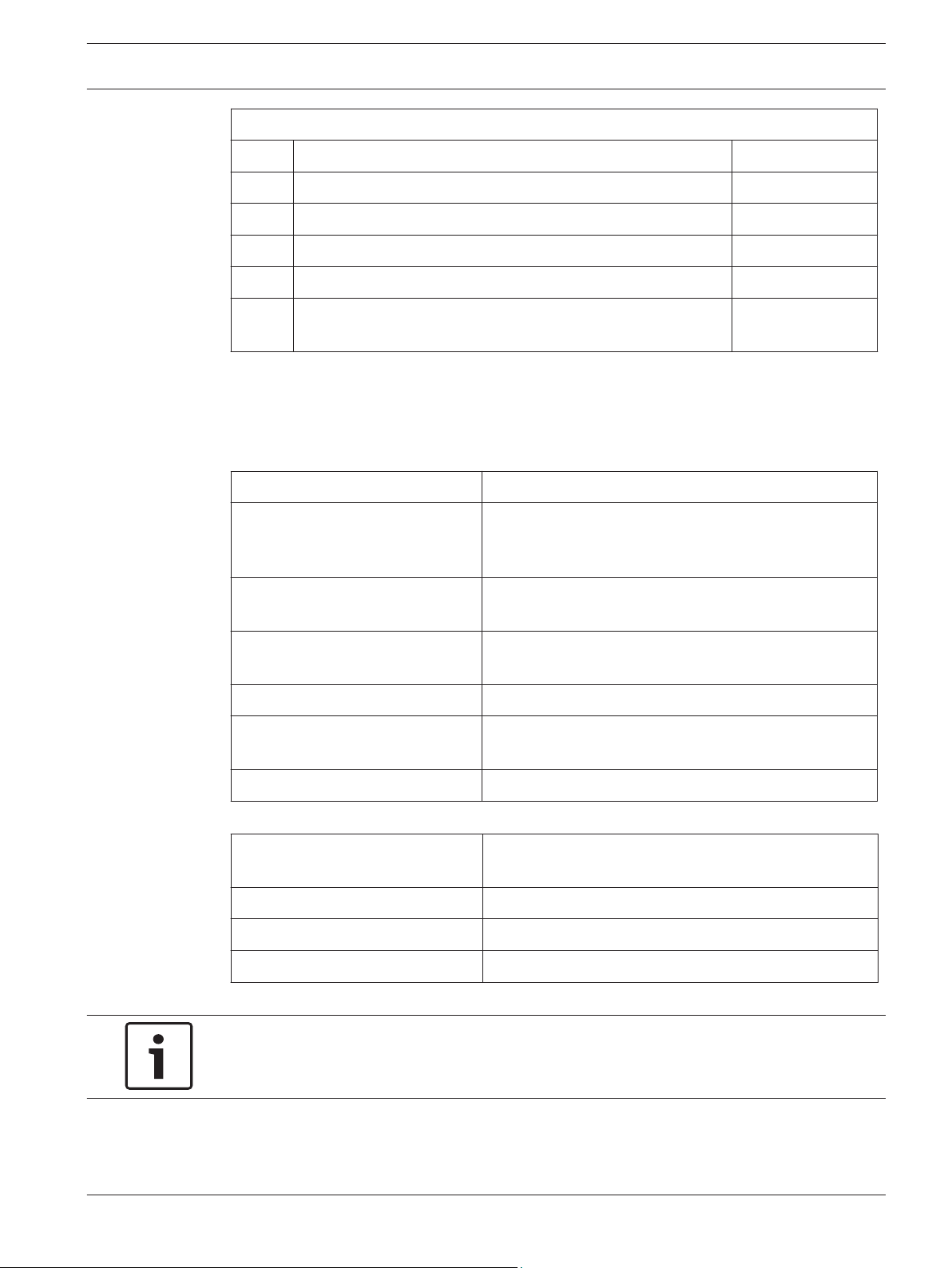
Access Easy Controller 2.1 Functional Features
Access Easy Controller 2.1 Functional Features
Item Description Remarks
1 Door access control X
2 Intrusion alarm/input monitoring X
3 Output device control (on/off) X
4 Time attendance clocking X
5 Email messaging upon triggered events X
6 SMS messaging upon triggered events X
7 View Live and Playback videos X
8 Video verification for door access X
9 Search event videos for verification X
10 Modem dial-in from remote PC X
11 Backup database (parameters, activities & audit log) into
compact flash
X
12 Integrate to Access Easy Master Controller X
13 Priority anti-passback zone (254 zones) operation and only
registered if door contact detect door being open by
cardholder
Robert Bosch (SEA) Pte Ltd Software Manual 2013.05 | V1.0.5 | F.01U.122.797
X
Page 12

12 en | Introduction Access Easy Controller 2.1
Access Easy Controller 2.1 Functional Features
Item Description Remarks
14 Door forced open alarm delay X
15 Door held open pre-warning X
16 Reader lockout after a pre-define invalid card event X
17 Elevator access control X
18 Integrated door access reader with arm/disarm function
(using same reader)
19 Special cardholder with extended duration for door strike and
keypad
20 One time access X
21 Dual card entry (2 man rule) X
22 Card enrollment function for any card with unknown card
format
23 Option to unlock door by schedule only after a valid access
card is presented
24 Input monitoring (door contact, request-to-exit, alarm input
points) supports configurable 2 state non-supervise, 2 state
supervise and 4 state supervise for all input points in the
controller.
Configurable:- 2
state nonsupervise
(no EOL), 2 state
supervise (6.8K
EOL), 4 state
supervise (12K &
15K EOL)
25 Card database import and export function (in CSV format) X
X
X
X
X
26 Real time activities and status update X
27 Department field in the card assignment 30 alpha-numeric
characters
28 Advance IO (guard tour, feed through, OR, AND, XOR, NAND,
X
up/down counter, exit door, one shot and intrusion)
29 Support interlock/mantrap operation using advance IO
X
configuration.
30 Browser login encryption 128 bits SSL
Maximum Capacities
Item Description Capacity
1 Wiegand reader support 32
2 Input monitoring points 64
3 Relay outputs 64
2013.05 | V1.0.5 | F.01U.122.797 Software Manual Robert Bosch (SEA) Pte Ltd
Page 13
Access Easy Controller 2.1 Introduction | en 13
Maximum Capacities
Item Description Capacity
4 Cardholder 20480
5 Transaction history 100,000
6 Audit log 1023
7 Compact flash size 512 MB
2.2
8 Video camera to a reader or input/output point or advance IO
function block
3
Powering up Access Easy Controller 2.1
Access Easy Controller 2.1 is incorporated with some beep sounds in the system for you to
identify the stages/faults in the system/events etc. The table below lists the beep sounds that
you may encounter while booting the system.
Types of Beep during Boot up Significance/Stages in Booting Sequence
2 short beeps When the panel is powered up, a boot up check will be
carried out. The CPU will authenticate with its security
key before proceeding to run the software
Continuous beep for 60 seconds Occurs after boot up check and if verification of the
security key fails.
3 short beeps Occurs when the system starts to launch the back end
program.
Continuous beep for 30 seconds Occurs when any decrypting failure takes place.
5 beeps in ascending tune Occurs when all the back end programs are launched
successfully.
8 beeps Occurs when the boot up is complete.
Types of Beep when Software is
Running
2 short beeps Faults occur in Webacu file.
3 short beeps Faults occur in Webcru file.
4 short beeps Faults occur in Webser file.
Notice!
The software errors are auto fixed in the program.
Robert Bosch (SEA) Pte Ltd Software Manual 2013.05 | V1.0.5 | F.01U.122.797
Significance
Page 14
14 en | Overview of Access Easy Controller 2.1 Access Easy Controller 2.1
3
Overview of Access Easy Controller 2.1
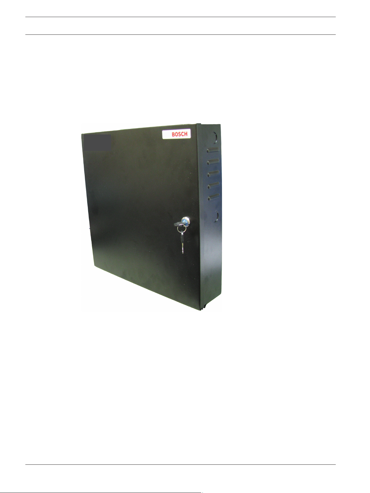
The basic AEC2.1 system consists of a single metal enclosure with three components: CPU, 4Reader board, and Power Supply Unit (PSU). Space is provided for a 12-volt standby battery
to sustain the system in event of a power failure. The PSU in the controller has an input power
of 100~240 VAC.
The enclosure is key locked and is equipped with a tamper switch to detect any tampering of
the panel, and/or when the controller door is being opened.
Figure 3.1: AEC2.1 Main Enclosure
In its minimum configuration, an AEC2.1 system supports one 4-Reader board. The board
comes with, 4 card reader, 8 input, and 8 output ports to support all necessary hardware
(door lock/strike outputs, door contact inputs and request-to-exit inputs). A full AEC2.1
system supports up to a maximum of 16 interface boards (eight 4-Reader boards and eight 8IO boards). This allows the AEC2.1 system to support up to 32 card readers, 64 alarm type
input and 64 controllable output points.
CPU Board - The CPU board contains a microprocessor, RAM memory and all necessary
electronic circuitry to interact with other circuit boards. The CPU board contains the hardware
and software needed to interface to an Ethernet-type network and to communicate with host
computers using TCP/IP protocol.
4-Reader Board - The 4-Reader board is an interface board for AEC2.1. The reader board
contains all circuitry necessary to interface with, and operate, up to four card readers. The
reader board also provides wiring termination points for the readers, door strikes or magnetic
2013.05 | V1.0.5 | F.01U.122.797 Software Manual Robert Bosch (SEA) Pte Ltd
Page 15
Access Easy Controller 2.1 Overview of Access Easy Controller 2.1 | en 15
locks, door contacts and request-to-exit devices. The first interface board of the system
communicates with the CPU board via the RS232 channel. The subsequent interface boards
are linked through a multi-drop communication channel, RS485, to form the system. The PSU
supplies the required 12V DC power to the board.
8-Input-Output Board -The 8-IO board is an interface board for AEC2.1. The 8-IO board
provides the necessary circuitry to monitor 8-alarm type (non-reader) inputs, and to control up
to eight external devices, such as bells, fans, lights, etc. The board also provides wiring
termination points for the input and output devices. The first interface board of the system
communicates with the CPU board via the RS232 channel. The subsequent interface boards
are linked up through a multi-drop communication channel, RS485. The PSU supplies the
required 12V DC power to the board.
Access Easy Extension - Access Easy Extension is a metal enclosure identical in size to the
basic AEC2.1. The Extension unit contains a Power Supply Unit, and space to install up to two
additional 4-Reader boards and/or 8-IO boards. Space is provided for an optional 12V, 7AH
standby battery to sustain the system in time of power failure.
Notice!
AEC2.1 does not come with the 12V DC standby battery.
Robert Bosch (SEA) Pte Ltd Software Manual 2013.05 | V1.0.5 | F.01U.122.797
Page 16

16 en | Accessing Access Easy Controller 2.1 Access Easy Controller 2.1
4
4.1
4.2
Accessing Access Easy Controller 2.1
This chapter explains the basic information on how to access the AEC2.1 and log onto the
software.
A standard web browser program such as Internet Explorer is required to access or monitor
the AEC2.1.
Connecting to Access Easy Controller 2.1
Before accessing the AEC2.1, it must be configured and integrated to the existing computer
network.
As this integration requires knowledge on networking, it is the responsibility of the System
Installer to work closely with your company's Network Administrator to do the initial set up.
However, for general knowledge, a description is presented in Appendix A. Refer to APPENDIX
A, page 179 for more information. For users accessing the AEC2.1 using their own computer,
refer to the section ‘Setting to be made to the Web Browser’.
System Requirements
Check the following minimum hardware and software requirements on the Remote PC to
access the AEC2.1.
– 10/100Base-T Ethernet card
– CD drive
– Operating System (Windows)
– Windows 7/XP
– Standard Web browser (for Internet Explorer version 7, 8 and 9)
Video Requirements:
– .NET Framework 3.0
(.NET Framework 3.5 for VideoSDK 5.x)
– DirectX
– Video card that supports DirectX
– Internet Explorer
The AEC2.1 can be accessed after all the preceding system requirements are met.
Notice!
Video integration features are available on Windows 7/XP OS only.
4.3
2013.05 | V1.0.5 | F.01U.122.797 Software Manual Robert Bosch (SEA) Pte Ltd
Accessing Access Easy Controller 2.1 Software
A working knowledge of Windows and Internet Explorer is required to access the AEC2.1.
To get connected to AEC2.1, launch the web browser program and key in the AEC2.1's URL
address followed by the <Enter> key. The factory default URL for AEC2.1 is 192.168.0.41.
Page 17
Access Easy Controller 2.1 Accessing Access Easy Controller 2.1 | en 17
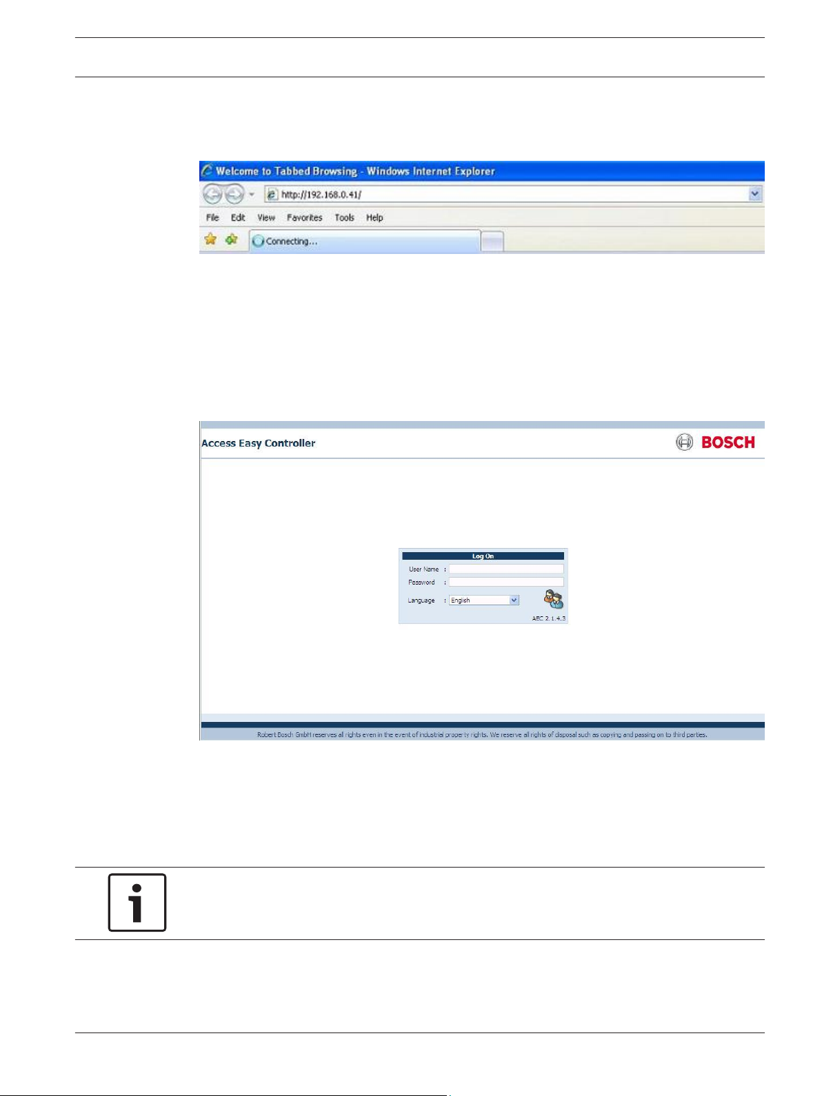
The screen below shows an example of the web browser with the default URL address for the
AEC2.1.
Figure 4.1: AEC2.1 Default URL address
Note: All screens are presented in Internet Explorer 7.0.
This will bring up the login page.
4.4
Logging into Access Easy Controller 2.1
The login screen appears as shown below.
This User Login dialog box provides a security control that protects the AEC2.1 from
unauthorized access. Enter your user id and password in the User Name and Password field
to gain access to the AEC2.1. Select the required GUI language from the language dropdown.
The system allows up to 8 users to logon the same AEC2.1 using different computers.
Notice!
The User ID and Password are case-sensitive and can be changed.
Robert Bosch (SEA) Pte Ltd Software Manual 2013.05 | V1.0.5 | F.01U.122.797
Page 18
18 en | Accessing Access Easy Controller 2.1 Access Easy Controller 2.1
4.4.1
When the AEC2.1 is first installed, there is only one assigned user ID and password. This
default user ID is known as the Super-user and usually assigned to the AEC2.1 System
Administrator. The Super-user has the full access rights to all features of the AEC2.1, including
the AEC2.1 Utility programs. The user id and password of the Super-user ID can be changed
but the access rights cannot be changed.
The default IP Address - 192.168.0.41, User ID = user1 and Password = 8088
Notice!
Once the system is commissioned and handed-over, change the default User ID and Password
as soon as possible to prevent unauthorized access.
Logging in Access Easy Controller 2.1
1. Enter your assigned User ID in the User Name field.
2. Enter your assigned Password in the Password field.
3. Select the required GUI language from the Language dropdown.
4.
Click the login
Notice!
Changing the language in the login page changes the GUI language interface and not the data
in the database.
If you do not know your User ID and Password, contact your AEC2.1 system administrator to
obtain them. User IDs and Passwords are configured by the AEC2.1 system administrator.
button to log into AEC2.1.
4.4.2
Logging off from Access Easy Controller 2.1
After you finish your session with AEC2.1 or need to be away from the computer, it is
recommended to log off from the AEC2.1.
To log off, click the logout
Notice!
ALWAYS LOG OFF BEFORE LEAVING THE COMPUTER!
link on the top of the page.
2013.05 | V1.0.5 | F.01U.122.797 Software Manual Robert Bosch (SEA) Pte Ltd
Page 19
Access Easy Controller 2.1 Installing ActiveX and VideoSDK | en 19
5
5.1
Installing ActiveX and VideoSDK
Install ActiveX and VideoSDK to access the video features of AEC2.1.
The ActiveX and Video SDK is installed automatically when the AEC2.1 system is set. If the
Video SDK is not installed automatically then you can install it from the Utility CD or retrieve
the files from the VideoSDK page. Refer to Video SDK, page 161 in Advance settings for more
information.
Tips: If the ActiveX control is not shown correctly after auto-installation of ActiveX / Video
SDK, please restart the browser and try again. If problem still persists, please follow the
Uninstall Procedure for ActiveX and VideoSDK, page 20 and proceed with manual/auto
installation.
Refer to the section below for installing VideoSDK from the utility CD.
Notice!
The system will auto install VideoSDK only if a camera is configured.
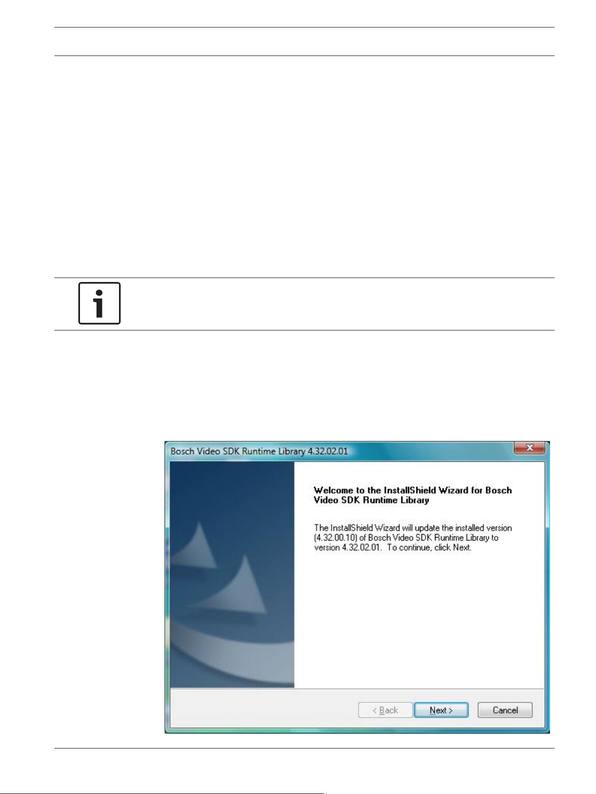
Installation Procedure for VideoSDK
The steps below will guide you through the installation of the Video SDK.
1. Place the CD in the CD-ROM and open the folder BOSCH VideoSDK. In the BOSCH
VideoSDK folder look for the .exe file in the installer folder.
2. Double click the .exe file. The screen below appears. Click the Next button to proceed
with the installation.
Robert Bosch (SEA) Pte Ltd Software Manual 2013.05 | V1.0.5 | F.01U.122.797
Page 20
20 en | Installing ActiveX and VideoSDK Access Easy Controller 2.1
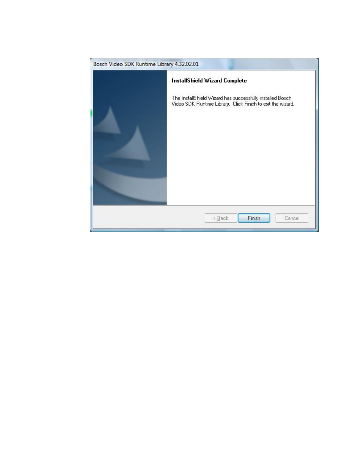
3. Follow the instructions in the install Shield window to complete the installation. After the
installation is completed successfully the screen below appears.
5.2
This completes the BOSCH VideoSDK installation.
Uninstall Procedure for ActiveX and VideoSDK
Follow the procedures below to uninstall ActiveX and VideoSDK based on the version of
VideoSDK.
Please close all the browsers and any other applications that is using ActiveX and/or
VideoSDK.
Procedure for Video SDK 4.x
Uninstall AEC ActiveX
– For 64 bit system:
Go to “C:\Program Files (x86)\Internet Explorer” and delete AECVideoActiveX.ocx
– For 32 bit system:
Go to “C:\Program Files\Internet Explorer” and delete AECVideoActiveX.ocx
Uninstall VideoSDK 4.x
– In ‘Control Panel’ > ‘Programs’ > ‘Programs and Features’, remove/uninstall ‘Bosch Video
SDK Runtime Library 4.X’
Procedure for Video SDK 5.x
Uninstall AEC ActiveX
1. Go to '(OS installation Drive)\ProgramData\BOSCH\AEC2.1' folder. Run Uninstall
ActiveX.bat as Administrator.
2013.05 | V1.0.5 | F.01U.122.797 Software Manual Robert Bosch (SEA) Pte Ltd
Page 21

Access Easy Controller 2.1 Installing ActiveX and VideoSDK | en 21
2. Delete '(OS installation Drive)\ProgramData\BOSCH\AEC2.1' folder. (Please make sure
Browser is closed).
Notice!
If ProgramData folder is not visible, make sure that you have enabled the option to show
hidden files and folders. It can be done in Windows Explorer, press 'Alt' > 'Tools' > 'Folder
options...' and select 'Show hidden files, folders and drives'.
Uninstall VideoSDK
– In ‘Control Panel’ > ‘Programs’ > ‘Programs and Features’, remove/uninstall ‘Bosch Video
SDK 5.X’
Robert Bosch (SEA) Pte Ltd Software Manual 2013.05 | V1.0.5 | F.01U.122.797
Page 22
AE C2 .1 L ogi n
Ac tivity
Ca rd
Co nfig ura tion
Sy ste m
Da te & Ti me
Ne two rk S ett ing
De vic e
Device Control
Adv anc e I/O
Ala rm Zon e
Sc hed ules
Ho liday s
Re por t
Ac tivi ty
Ca rd
De vic e
Co nfig ura tion
Import/Export
Di al In Us er
Cr iter ia
Vid eo
Ca mer a
De vic e Ty pe
Mi sce llane ous
Do or
Inp ut
Ou tput
Function
Advanced
Vid eo Setup
SM S S er ver
Cu sto mer Lo go
De fau lt S ettin gs
Inp ut S tat e
Re ade r
Inp ut
Re gula r H olida y
Sp eci al H olida y
AE MC IP
Vid eo SDK
De fau lt S ettings
Sy ste m L og
Au dit L og
IO Configuration
Time Attendance
APB
Output
Input
Door
Restore & Alarm
Valid & Alarm
Alarm
All
Transactions
Card Administration
Assignment
Enrollment
Batch Card
Access Groups
Card Format
Department
Reset APB
Default Setting
Database Backup/Restore
Firmware Upgrade
System Maintenance
Advance Settings
Email Server
System IP Address
User Administration
Online Swipe
Surveillance
Video Verification
Camera Monitoring
Input Camera
Output Camera
Em ail
SM S
Me ssa ge
Email/SMS Settings
User Profile
User
APB
Access Group
Reader
Input
Output
Advance I/O
Camera
Schedule
Regular Holiday
Special Holiday
Default Settings
Advance I/O Camera
LAN Converter
22 en | Main Menu Groups Access Easy Controller 2.1
6
Main Menu Groups
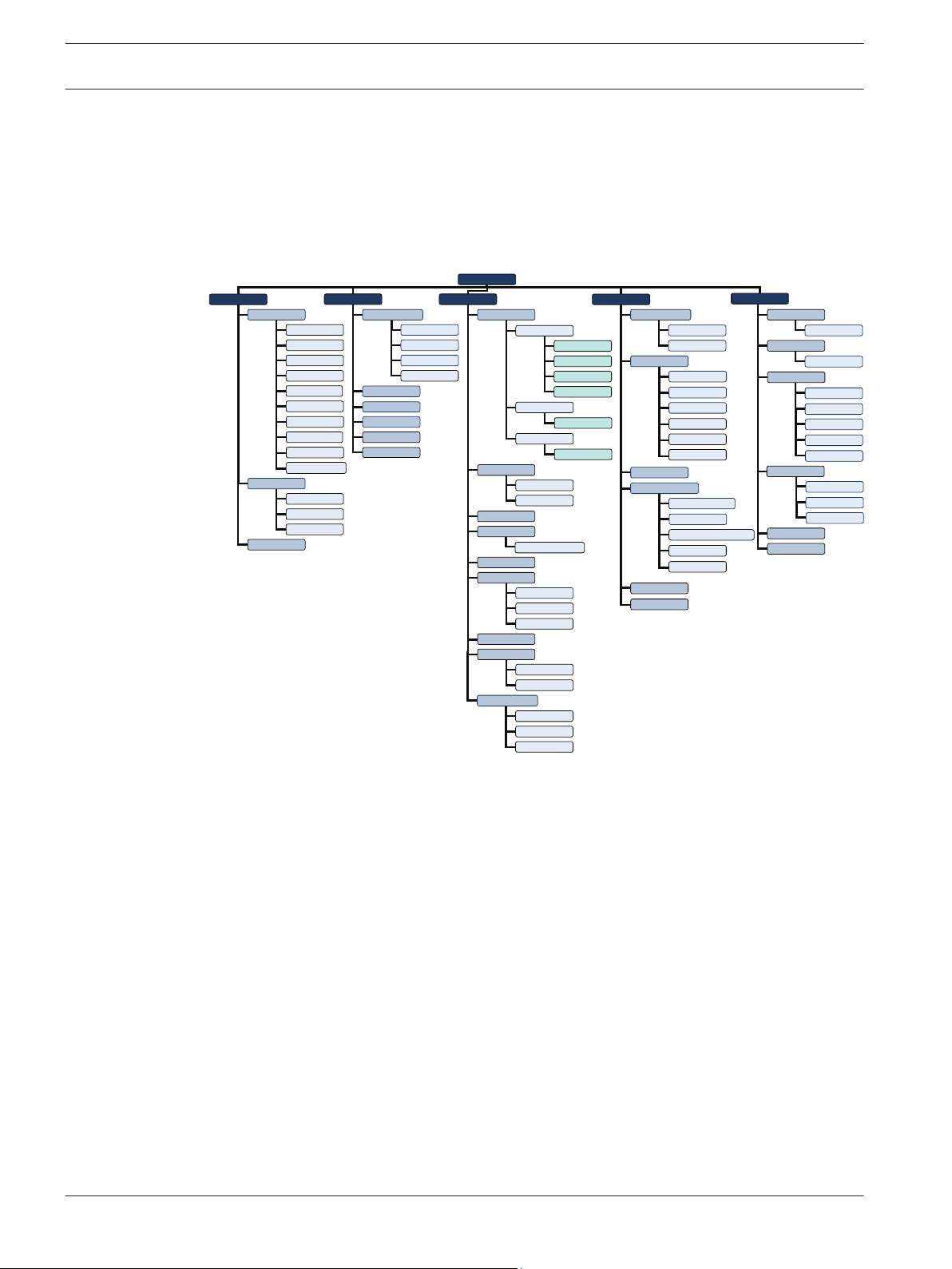
The AEC2.1 home page shows a list of the main menu features available in the AEC2.1 system.
The Alarm Transactions page is the default home page for AEC2.1.
The diagram below shows the structure of the menus and submenus available in the AEC2.1
software interface.
The main menus and its features are explained in detail in the following chapters. A brief
description of each menu is explained below.
6.1
6.1.1
Menu Description
Following are the main sections of Menu Description:
Activity
The Activity menu shows all the transactions generated due to access control, system control
and alarm conditions. Based on the transaction type the transactions are categorized into the
following groups: All, Alarm, Valid & Alarm, Restore & Alarm, Time Attendance, APB and
Video Verification. You can select a specific transaction group tab or view All Transactions.
The Transactions page also shows the online swipe, surveillance and cameramonitoring. The
onlineswipe function lists the last three valid cardholders who tried to access the AEC2.1
system. The surveillance window displays the live event video, when an alarm event is
triggered in the camera configured location. In the surveillance window you can view the Live
video, Playback video, and compare the two videos. The camera monitoring function allows
you to view the live streaming video of the camera for monitoring. You can also view the
playback video of the camera for a selected date and time in the camera monitoring window.
2013.05 | V1.0.5 | F.01U.122.797 Software Manual Robert Bosch (SEA) Pte Ltd
Page 23

Access Easy Controller 2.1 Main Menu Groups | en 23
The video verification function enables automatic live video display of the access point for
comparison with cardholder’s photo for the operator to grant access or deny access to the
cardholder.
The Activity menu relates to the manual control of the system hardware and consists of Door
Control, Input Control and Output Control.
6.1.2
6.1.3
Card
The card menu relates to the card parameter set up, such as Card Number, Cardholder’s
name, Cardholder’s photo etc including the right to Arm/Disarm an alarm zone.
The card menu also relates to the Access Groups that allows to categorize the Card Readers
into different Access Groups for Cardholder’s access rights. A cardholder can have access
rights for a maximum of two access groups.
In the card menu option you can create Card Formats, Departments and Reset the Anti
Passback settings for a cardholder.
Configuration
The configuration menu relates to the door settings and camera settings of the system. In the
camera settings a maximum of three cameras can be configured to each reader or input/
output point or advance IO function block.
In the card menu option you can create alarm zones, criteria settings, configure Email, SMS
and Message settings.
Advance IO setup is used to enable the rerouting of physical or logical information from one
operation to another.
In the configuration menu you can add device types and configure cameras to the AEC2.1
system. The auto detect camera option lists the available cameras.
Schedules are used to set-up time intervals for use in access system and hardware control.
Holidays are used to define and assign programmable holiday dates.
6.1.4
Robert Bosch (SEA) Pte Ltd Software Manual 2013.05 | V1.0.5 | F.01U.122.797
System
User ID’s and Password including access rights to the various menu items are set in the
system menu. You can configure the Panel IP address, Dial In settings, and the AEMC IP
settings. The system menu allows you to set the date and time of the panel.
Database Backup is used to backup (write) all databases into the flash memory of the
controller and further download to the hard disk of a PC. You can define a time in the AEC2.1
to perform an automatic backup to the flash memory. The database backup is also used for
database recovery.
Firmware upgrade is used to upgrade firmware or program upgrade. Video update is used to
update the video versions.
Page 24
24 en | Main Menu Groups Access Easy Controller 2.1
Reboot Panel function is used to reboot the AEC2.1 system. A reboot is usually performed
after resetting the AEC2.1 IP Address or during a firmware upgrade. Shutdown Panel function
is used to shutdown the AEC2.1 system. A shutdown is usually performed after hardware
upgrades.
6.1.5
6.1.6
6.2
6.3
Report
This menu item allows you to print reports based on transactions, cardholders violating the
APB settings, access groups, schedules, user log, Input points, camera, holidays etc.
You can provide a main header and sub headers for the reports generated from the AEC2.1
system.
Logout
The Logout option is used to log off from AEC2.1 system.
Navigating through Access Easy Controller 2.1 Page
Click the main menu followed by the sub menus to access the web page of the functions
selected.
Usage of the Buttons
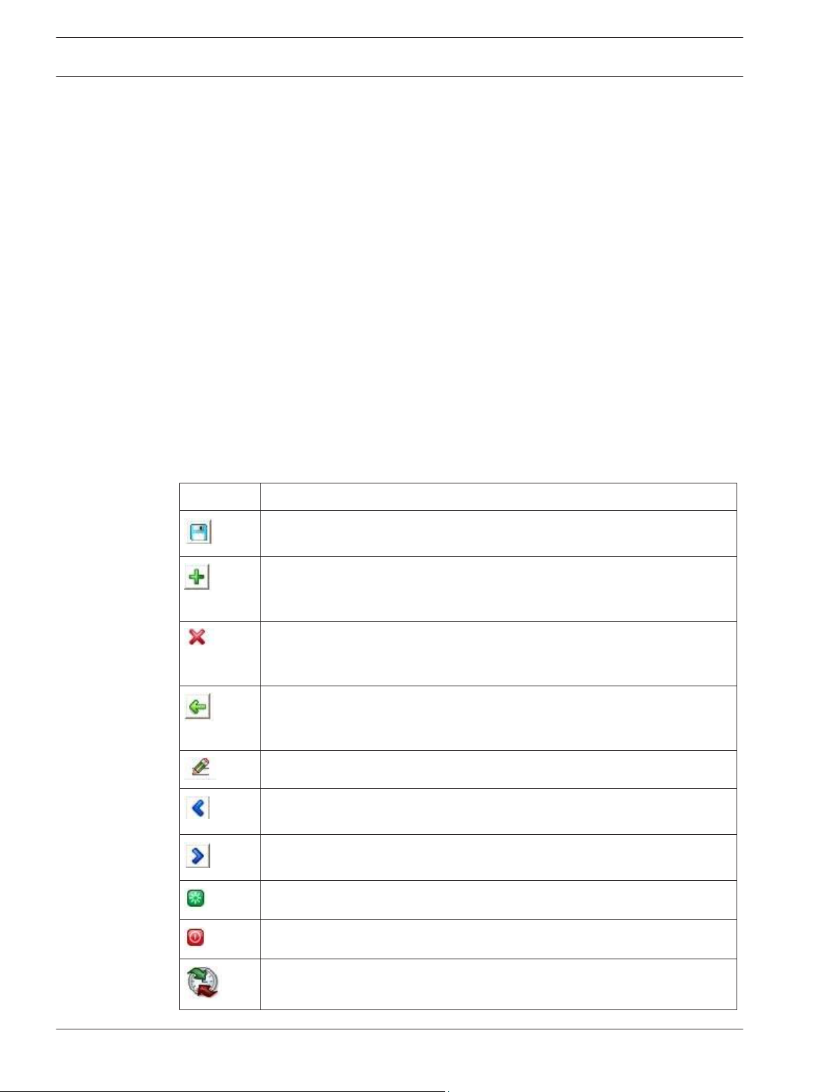
The table below shows the functions of the action buttons available in AEC2.1 webpage.
Button Description
The save button saves the current settings to the (Dynamic RAM) DRAM and
refreshes the current web page
The add button performs the following functions:– carries out the addition process
– adds selected parameter to the list window
The delete button performs the following functions:– deletes all configurable parameters and sets it to default
– removes selected parameter from the list window
The previous button performs the following functions
– does not save the settings made on the current screen and
– brings up the previous screen
The edit button, edits the current parameter settings
The move left button, moves a selected parameter from the right list window
to the left list window
The move right button, moves a selected parameter from the left list window
to the right list window
The reboot panel button, reboots the AEC2.1 system
The shutdown button, shuts down the AEC2.1 system
Time synchronization button, synchronizes the AEC2.1 system time to the
server time or PC time
2013.05 | V1.0.5 | F.01U.122.797 Software Manual Robert Bosch (SEA) Pte Ltd
Page 25
Access Easy Controller 2.1 Main Menu Groups | en 25
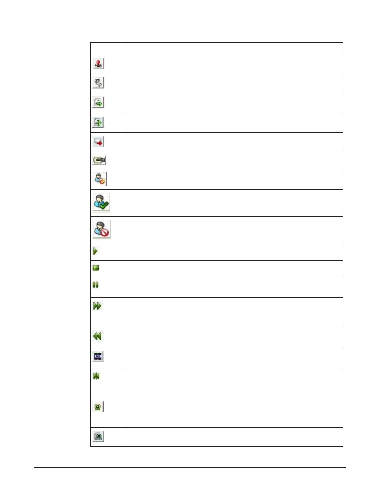
Button Description
The acknowledge alarm button, acknowledges the Alarm transactions
The alarm audio on/off button, silents the audible tones on the CMC
The download button downloads the files to the desired location on the PC
local drive
The upload button uploads the files from the PC to the system
The send button, sends Email or SMS to the addressees mentioned
The camera button is used to view the video clip of an event
The reset APB button, resets the APB violation
The grant access button is used in video verification to grant door access to
the cardholder
The deny access button is used in video verification to deny door access to
the cardholder
The play button, plays the Live or Playback video
The stop button, stops the streaming of the Live or Playback video
The pause button, pauses the streaming of the Playback video. The pause
button is available in the playback mode only
The fast forward button streams the video in a fast mode and streams the
video in forward motion. The fast forward button is available in the playback
mode only
The rewind button streams the video in the backward direction. The rewind
button is available in the playback mode only
Downloads the current streaming video. The downloaded video is saved in the
configured location. Refer to Miscellaneous, page 101 for more information.
The jump to event button starts the video streaming from the moment the
event was triggered. In other words it ignores the pre and post event duration
timing.
The snapshot button is used to take a still image from the streaming video.
The image file is saved in the configured location. Refer to Miscellaneous, page
101 for more information.
The view report button is used to preview the configured report.
Robert Bosch (SEA) Pte Ltd Software Manual 2013.05 | V1.0.5 | F.01U.122.797
Page 26

26 en | Activity Access Easy Controller 2.1
7
7.1
Activity
The Activity menu relates to the transactions generated by the AEC2.1 system and the video
features available in AEC2.1. The activity menu also relates to the manual control of the
system hardware.
The different features of the activity menu are explained in the following sections.
The Activity main menu consists of the following submenus:
– Transactions
– Device Control
– Default Settings
The three submenus are explained in detail in the following pages.
Transactions
The transactions submenu lists all the transactions or events triggered by the AEC2.1. Every
activity transaction such as Door Forced Open, Door Held Open, Access Granted, Access
Denied etc. are captured by AEC2.1 and displayed on the transactions web page in real-time
mode with the transaction occurrence date and time.
The transactions window consists of two window panes, the left pane and the right pane. The
left pane displays the transactions performed by AEC2.1 and the right pane displays the
online swipe, surveillance and camera monitoring features.
The transactions are categorized into different groups based on the event triggered or actions
performed on the AEC2.1. The transactions are categorized as follows: All, Alarm, Valid &
Alarm, Restore & Alarm, Time Attendance, APB and Video Verification. You can select a
specific transaction event or view all the transactions by selecting the All tab.
AEC2.1 can store up to 100,000 activity transactions and the Alarm transactions window is
the default screen for AEC2.1.
Note: The default view of the transaction screen can be changed in the default settings page
of the activity menu. Refer to Activity - Default Settings, page 47 for more details.
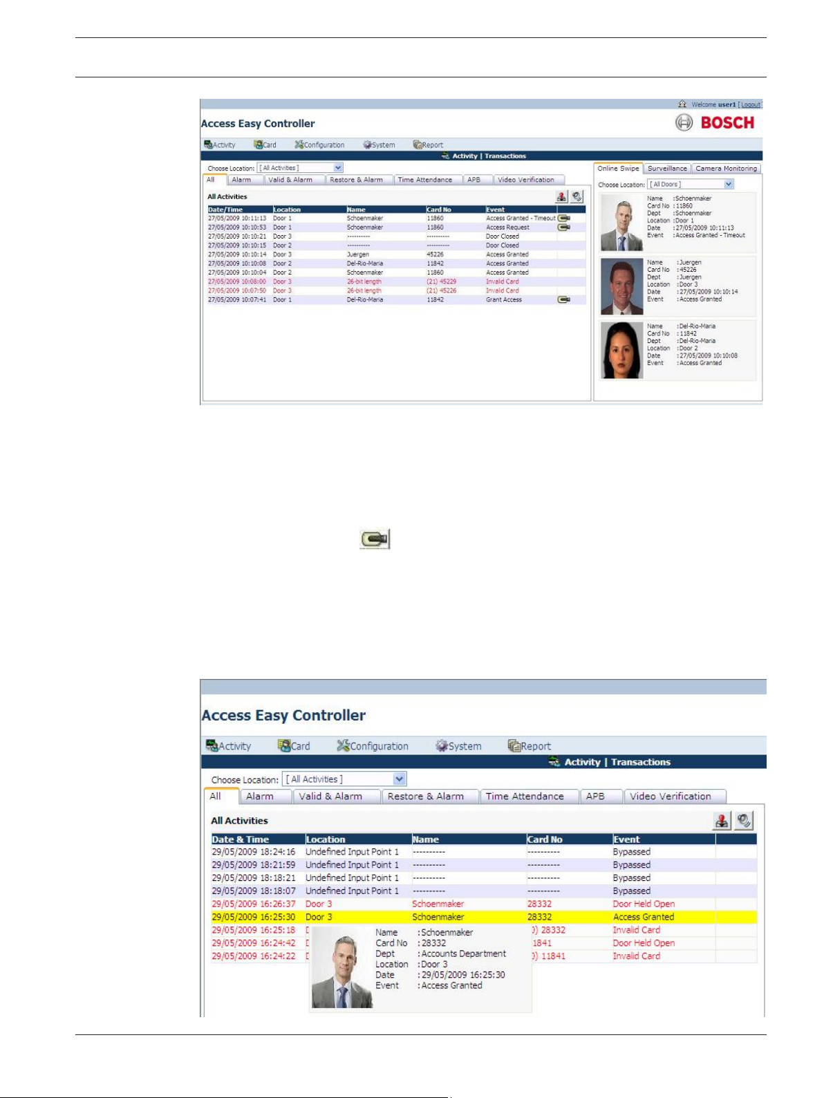
The screen below shows the transaction window with the All tab selected. You can select a
transaction group by selecting the transaction group tab you want to view.
2013.05 | V1.0.5 | F.01U.122.797 Software Manual Robert Bosch (SEA) Pte Ltd
Page 27
Access Easy Controller 2.1
Activity | en 27
The transactions webpage displays the details of the event triggered or the action performed
on the AEC2.1 system. The transactions webpage lists the name, card number, location where
the event or action was performed, the date and time when the event or the action was
performed and the description of the event or action performed.
A camera icon is displayed along the transactions row if a camera is configured for the
location. Click the camera icon to view the recorded events or action video clip. These
event videos can be downloaded to the PC for later investigation. The videos are recorded in
the video device and not on the AEC2.1 system.
You can view the cardholder's profile by moving the pointer along the card number column.
This feature is available in all the transaction groups. The screen below shows an example of
the cardholder's profile details as you move along the card number column.
Robert Bosch (SEA) Pte Ltd Software Manual 2013.05 | V1.0.5 | F.01U.122.797
Page 28

28 en | Activity Access Easy Controller 2.1
The cardholders profile window also shows the Reset APB button if a cardholder has APB
violation. You can reset the Anti-Passback violation for the cardholder by clicking the Reset
APB button.
Note: You should have the access rights to reset the anti-passback option. Refer to Reset APB,
page 72 for more details.
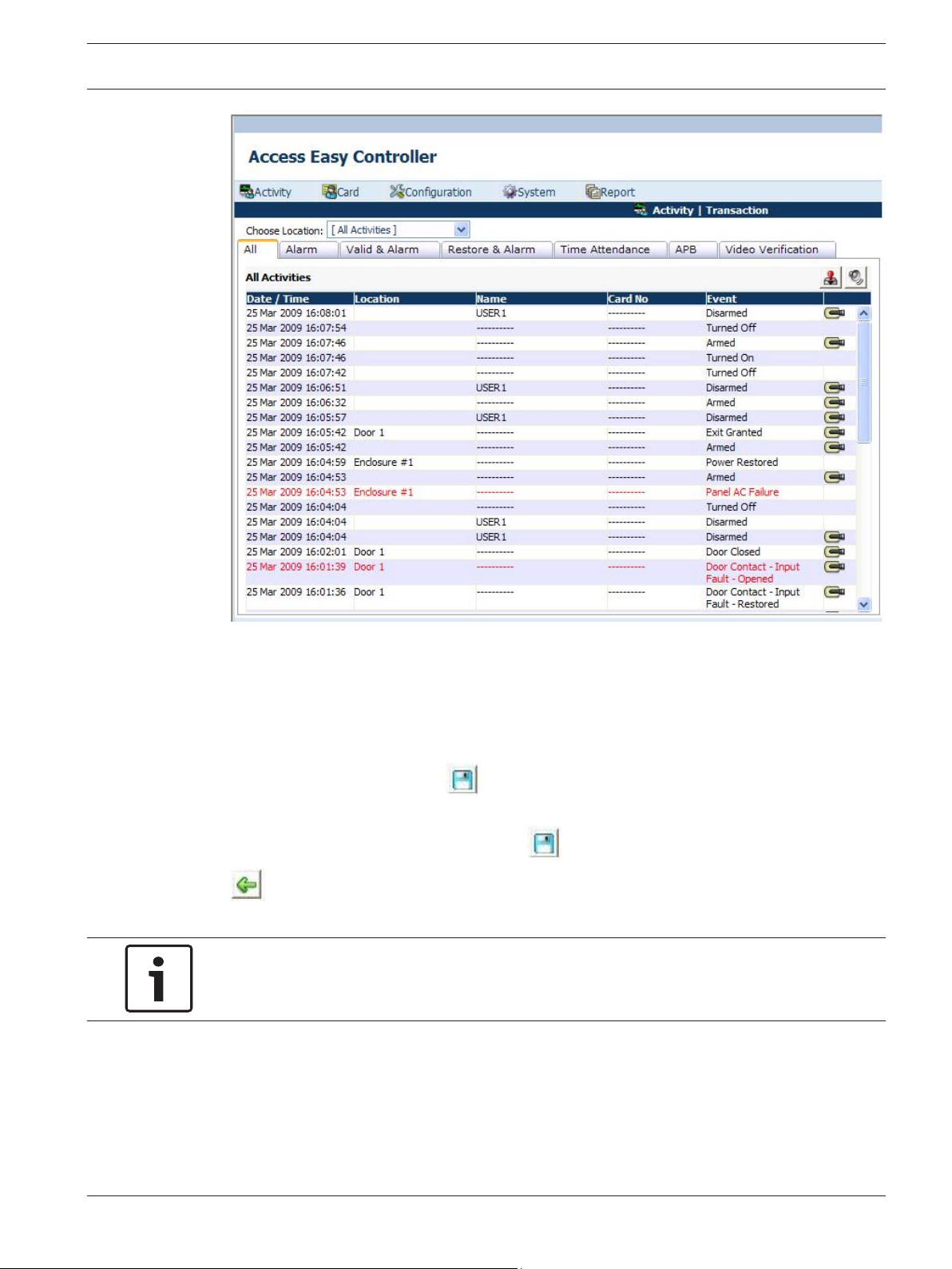
The features of activity transactions are as follow:– All Alarm transactions have red colored text wording while other transactions have black
colored text wording.
–
Click the acknowledge
acknowledge button is clicked the alarm audio is silenced. The text of the alarm
transactions remain red even after the transactions are acknowledged.
– When the web page refreshes or is acknowledged, either automatically or through user
intervention the transactions background is replaced with grey background.
All the alarm transaction tabs (All, Alarm, Valid & Alarm, Restore & Alarm) consists of two
button to acknowledge the alarm transactions. Once the
7.1.1
action buttons namely the acknowledge button
the acknowledge button to acknowledge the alarm transactions.
The AEC2.1 system sends a beep sound every time there is a transaction in the system. Click
the speaker on/off
The available Transaction groups are explained in detail below.
button to mute the beep sound.
and the speaker on/off button . Click
All
Displays all the transactions performed by the AEC2.1 system. The screen below shows the All
transactions window. The transactions page is explained in detail in the previous paragraphs.
2013.05 | V1.0.5 | F.01U.122.797 Software Manual Robert Bosch (SEA) Pte Ltd
Page 29
Access Easy Controller 2.1 Activity | en 29
The Choose Location dropdown at the top of the page lists all the doors configured to the
system. You can configure a group of doors as a set in Setting - Door Group… option available
in the choose location dropdown. Select Setting - Door Group… from the Choose Location
dropdown as shown below.
The screen below appears to select the doors to be added to the Door Group.
Select the check box corresponding to the respective doors which has to be configured in the
Door Group set. Click the save
button to save the locations in the door group. Select the
All Items option if you want to select all the doors in the locations list to the door group. After
selecting the required doors click the save button to save the settings. Click the back
button to cancel the settings and return to the transactions page.
Notice!
The configured location is user based and is available to the user who configured the door
group.
After saving the settings the web page returns to the Transactions main page. Select a
location from the Choose Location dropdown to view the transactions/events of the AEC2.1
system at the selected location.
In the All transactions window, all the alarm transactions have red colored text while other
transactions have black colored text.
Robert Bosch (SEA) Pte Ltd Software Manual 2013.05 | V1.0.5 | F.01U.122.797
Page 30

30 en | Activity Access Easy Controller 2.1
7.1.2
7.1.3
Alarm
Displays the alarm events triggered by the system. Examples of Alarm transactions include
Access Denied, Door Held Open, Panel Tamper, Duress etc. For a detailed list on Alarm
transaction, refer to Activity Transactions.
When any of the Alarm Activity transactions is transacted, an alert audio tone is sent to the
Central Monitoring Computer (CMC). Ensure that the CMC's audio system is in working order
and the volume is set to a reasonable level.
The working procedure and the features available in Alarm transaction group is the same as
explained in the All transactions group. Refer to All, page 28 for more information about the
software interface and the features available in the Alarm tab.
Valid & Alarm
Displays transactions performed by the system. Examples of Valid transactions include Access
Granted, Turn On, Disarmed, Duration On etc. For a detailed list on Valid transaction, refer to
Valid Activity, page 193.
The working procedure and the features available in Valid & Alarm is the same as explained in
the All transactions group. Refer to All, page 28 for more information about the software
interface and the features available in the Valid & Alarm tab.
7.1.4
7.1.5
7.1.6
Restore & Alarm
Displays the Alarm and Restored transactions performed by the system. Examples of Restored
transactions include Door Closed, Tamper Restored, Alarm Restored and PowerRestored.
For a detailed list on Restored transaction, refer to Restore Activity, page 193.
The working procedure and the features available in Restore & Alarm is the same as explained
in the All transactions group. Refer to All, page 28 for more information about the software
interface and the features available in the alarm tab.
Time Attendance
Displays only Time Clocking transactions. Examples of Time Attendance transactions include
Clock In and Clock Out.
The working procedure and the features available in Time Attendance is the same as
explained in the All transactions group. Refer to All, page 28 for more information about the
software interface and the features available in the time attendance tab.
APB
Displays the list of cardholder's name who are currently present in the APB zone. Refer to the
Reset APB, page 72 for more information about Anti Passback.
The APB Zone dropdown at the top of the page lists all the APB Zones configured in the
system. Select a Zone from the Alarm Zone dropdown to view the list of cardholder’s who are
in the selected APB zone.
2013.05 | V1.0.5 | F.01U.122.797 Software Manual Robert Bosch (SEA) Pte Ltd
Page 31

Access Easy Controller 2.1 Activity | en 31
7.1.7
Video Verification
The video verification page displays the live video of the access point for comparison with the
cardholder's photo. This allows the door operator to grant or deny access to the cardholder
via webpage manually after verification. In an event where there is no action and the time-out
occurs, grant access or deny access is provided based on the option configured in the door
settings menu. Refer to the Door Settings (Card Reader Settings), page 74 for more
information.
If the user is in transaction view page (All, Alarm, Valid & Alarm, Restore & Alarm, Time
Attendance or APB) and upon receiving access request event the tab will automatically switch
to the video verification tab.
Video verification feature can be enabled or disabled based on schedules. Refer to Verification
Camera Setting, page 89 for more information.
Note: A maximum of three cameras can be configured to a card reader, input/output point or
advance IO function block.
The screen below shows the video verification page.
Click the grant access button to grant door access to the cardholder or click the deny
access button to deny door access to the cardholder.
Robert Bosch (SEA) Pte Ltd Software Manual 2013.05 | V1.0.5 | F.01U.122.797
Page 32

32 en | Activity Access Easy Controller 2.1
This view shows the Live video of all the cameras configured to the reader. Double click on
the main video to view the full screen video or select any small video at the bottom to view the
video in the main window.
The pending list at the bottom of the video verification tab lists the name and location of the
cardholder waiting for door access at different configured locations. Select each cardholder
from the list to grant or deny door access. The number of items is equal to the number of
cardholders waiting for access rights.
The grant access and deny access button will be disabled if the cardholder in the pending list
has been granted or denied access by another user.
Before the cardholder in the pending list is granted or denied access, another user flashes the
card on the same location it will overwrite the existing cardholder details in the pending list to
the latest cardholder details.
The current date and time is displayed at the top right of the page and the location of the
cardholder waiting for door access is described besides the video verification text. A sample
video verification window is shown below for reference.
In the earlier example as soon as Maria is granted or denied access her transaction can be
viewed in the online swipe window and Sachin’s video clips are displayed in the video
verification window.
7.1.8
2013.05 | V1.0.5 | F.01U.122.797 Software Manual Robert Bosch (SEA) Pte Ltd
Online Swipe
The online swipe function lists the last three valid cardholders with photo who tried to access
the system. The online swipe tab lists the cardholder's profile and a button to reset APB if the
cardholder has APB violation.
The screen below shows the Online Swipe window.
Page 33

Access Easy Controller 2.1
Activity | en 33
In the online swipe window all the alarm transactions and access denied events, APB violating
transactions are represented with a red border along the cardholder’s photo as shown below.
The invalid card actions are not recorded or represented in the online swipe window.
Robert Bosch (SEA) Pte Ltd Software Manual 2013.05 | V1.0.5 | F.01U.122.797
Page 34

en | Activity Access Easy Controller 2.1
34
For example in the preceding screenshot Maria Robinson is denied access due to APB
violation, click the Reset APB button to reset her APB violation. After resetting the APB
settings the cardholder can use the card again with the same access rights provided. The
screen below shows the reset option in the transactions and online swipe window. You can
reset the APB settings in the transactions and online swipe window.
Note: Only authorized users can reset APB violation.
2013.05 | V1.0.5 | F.01U.122.797 Software Manual Robert Bosch (SEA) Pte Ltd
Page 35

Access Easy Controller 2.1 Activity | en 35
This tab also provides an option to see the list of cardholder's who tried to access the system
at a particular door or group of doors.
The Choose Location dropdown at the top of the page lists all the doors configured to the
AEC2.1 system. You can configure a group of doors as one door group in Setting - Door
Group… option available in the Choose Location dropdown. Select Setting - Door Group…
from the Choose Location dropdown as shown below.
The screen below pops up to select the doors to be added to the Door Group.
Select the check box corresponding to the respective doors which has to be configured in the
7.1.9
Door Group set. Click the save
button to save the locations in the door group. Select the
All Items option if you want to select all the doors in the location list to the door group. After
selecting the required doors click the save
button to save the settings. Click the back
button to cancel the settings and return to the transactions page.
Surveillance
When an alarm event is triggered the surveillance window will automatically display the
surveillance Live video of the event location and the event details, if a surveillance camera is
configured for the event location. In the surveillance window you can view the Live and
Playback videos of the configured cameras. You can also compare the Live and Playback
videos in the surveillance window. The surveillance camera for door is set in the door settings
option, refer to Door Settings (Card Reader Settings), page 74 for more information.
Notice!
If an optional camera is configured for the event location without configuring a surveillance
camera, it is considered as no surveillance camera is configured for the event location.
The screen below shows the surveillance screen in the Live mode.
Robert Bosch (SEA) Pte Ltd Software Manual 2013.05 | V1.0.5 | F.01U.122.797
Page 36

36 en | Activity Access Easy Controller 2.1
The table below lists the function buttons available in the surveillance window of the AEC2.1
system. The buttons mentioned in the table below have the same functionality in all the video
feature tabs.
Button
Function
Compares the Live and Playback video
Toggles between the Live and Playback video
Plays the video. Starts the video streaming
Pauses the video streaming and this option is available in the Playback mode
only
Stops the video display or video streaming
The rewind button streams the video in the backward direction. The rewind
button is available in the Playback mode only
The fast forward button streams the video in a fast mode and streams the
video in forward motion. The fast forward button is available in the Playback
mode only
Downloads the current streaming video. The downloaded video is saved in the
configured location. Refer to Miscellaneous, page 101 for more information.
2013.05 | V1.0.5 | F.01U.122.797 Software Manual Robert Bosch (SEA) Pte Ltd
Page 37

Access Easy Controller 2.1
Activity | en 37
Button Function
The jump to event button starts the video streaming from the moment the
event was triggered. In other words it ignores the pre and post event duration
timing. Refer to Miscellaneous, page 101 for more information.
The snapshot button is used to take a still image from the streaming video. The
image file is saved in the configured location. Refer to Miscellaneous, page 101
for more information.
Camera 1 configured to the system. This camera is also known as main
surveillance camera.
Camera 2 configured to the system. This camera is also known as Optional
camera 1.
Camera 3 configured to the system. This camera is also known as Optional
camera 2.
The Auto Popup checkbox must be selected for the window to automatically switch to
surveillance window when there is an alarm event. If this check box is not checked then the
surveillance window will not switch automatically when there is an event. It is always
advisable to check this box as this helps in monitoring the events.
The event details section specifies the status, location and Date/Time of the triggered event.
The Status field refers to the current status of the event for example AccessDenied etc. The
Location field refers to the location where the event is triggered. The Date/Time field refers to
the date and time when the event is triggered.
You can view the Live and Playback mode in this window. Along the mode description field
you can see two function buttons namely the Compare button and the Toggle Live/Playback
button.
The toggle button
toggles between the Live and Playback mode. The toggle button
switches between Live mode and Playback mode . The function buttons in the
Live and Playback mode are explained in the earlier table. The Live video option displays the
live video of the selected camera and the playback option displays the event video with the
pre and post event duration. Refer to Miscellaneous, page 101 for more information.
You can view the live or playback video of all the cameras configured to the same reader as
the surveillance camera. The camera selection icons are available at the bottom of the
surveillance window.The default surveillance camera is set in the door settings menu. Refer to
Door Settings (Card Reader Settings), page 74.
The screen below shows the surveillance window in Playback mode.
Robert Bosch (SEA) Pte Ltd Software Manual 2013.05 | V1.0.5 | F.01U.122.797
Page 38

38 en | Activity Access Easy Controller 2.1
At the bottom of the surveillance window you will see the play, stop, snapshot and export
video clip buttons. Click the play button to start the video streaming, stop button to end the
video streaming, snapshot button to capture a still image from the streaming video and export
video clip to download the streaming video.
The Playback mode consists of more function buttons namely pause, rewind, forward and
jump to event. Click the pause button to pause the video streaming, rewind button to stream
the video in the backward direction, forward button to stream the video in the forward
direction, jump to event button to start the video streaming from the moment the event was
triggered.
Notice!
The pause button , rewind button , forward button and jump to event are
available in Playback mode only.
A compare option is provided in the surveillance tab to compare the live and playback video
of the selected camera. Click the compare button to compare the Live video and
Playback video simultaneously. The playback video starts and ends the video display with the
pre and post timer settings. Refer to Miscellaneous, page 101 for setting the pre and post
timer settings.
The screen below shows the compare window.
2013.05 | V1.0.5 | F.01U.122.797 Software Manual Robert Bosch (SEA) Pte Ltd
Page 39

Access Easy Controller 2.1 Activity | en 39
The function buttons have the same functionality as explained in the earlier paragraphs. Click
7.1.10
the back
Note: Double click on the video in the Live and Playback mode to view the enlarged video.
Note: The exported videos can be viewed using the player available in BOSCH VideoSDK
folder on the utility CD.
button to return to the Transactions | surveillance page.
Camera Monitoring
The camera monitoring tab is used to monitor the cameras configured to the AEC2.1 system.
When you select the camera monitoring tab you can view the live or the playback video for a
selected date and time.
The screen below shows the camera monitoring screen in the Live mode.
Robert Bosch (SEA) Pte Ltd Software Manual 2013.05 | V1.0.5 | F.01U.122.797
Page 40

en | Activity Access Easy Controller 2.1
40
Select a camera from the Live View dropdown, the dropdown lists all the cameras configured
to the AEC2.1 system. The function keys at the bottom of the preview window is the same as
explained in the surveillance menu. Refer to Surveillance, page 35 for more information about
the function keys.
The screen below shows the camera monitoring window in the playback mode.
2013.05 | V1.0.5 | F.01U.122.797 Software Manual Robert Bosch (SEA) Pte Ltd
Page 41

Access Easy Controller 2.1
Activity | en 41
Select a camera from the Playback dropdown, the dropdown lists all the cameras configured
to the AEC2.1 system.
When you are in the playback view, a date and time text box appears as shown above to view
the earlier recorded event videos. Click the Date Selector
button to select a date, and a
pop up appears as shown below.
Select the date to view the video of a recorded event. The selected date appears in the Date
box. Select the hour, minute and second from the respective dropdowns. Select a duration
from the duration dropdown. After all the settings are made the surveillance window will start
streaming the video.
If a duration is set the surveillance window will play video for the set duration only. If there are
no videos in the selected date and time then the AEC 2.1 did not encounter any event on the
selected date or time, try again with another date and time.
Robert Bosch (SEA) Pte Ltd Software Manual 2013.05 | V1.0.5 | F.01U.122.797
Page 42

Door Locked
Door Unlocked
Door Locked
0830hrs
1731hrs
Door Status
according to
Schedule
Manual Door
Control
command sent
Resultant
Door Status
1. Unlock Door at 0730hrs
2. Lock Door at 0800hrs
3. Lock Door at 1230hrs
4. Unlock Door at 1315hrs
0730hrs 0800hrs
0830hrs
0000hrs
1230hrs 1315hrs
2359hrs
1731hrs
Legend:
Door is permanently Unlocked
Door is permanently Locked
42 en | Activity Access Easy Controller 2.1
The function keys at the bottom of the preview window is the same as explained in the
surveillance menu. Refer to Surveillance, page 35 for more information about the function keys.
Note: Double click on the video in the Live and Playback mode to view the enlarged video.
Note: The exported videos can be viewed using the player available in BOSCH VideoSDK
folder on the utility CD.
7.2
7.2.1
Device Control
The device control is a submenu of the Activity menu. The device control submenu refers to
the manual door settings of the AEC2.1 system. The device control menu consists of three
tabs namely Door Control, Input Control and Output Control.
The three submenus are explained in detail in the following pages.
Door Control
The Door Control option allows you to check the status of the doors and momentarily unlock/
lock the door without having to be present at the door location. This is a manually operated
control and has priority over the system control. However, the system will resume normal
operation once it encounters a valid schedule interval.
Let's explain this with an example:
The door is scheduled as follows Unlock Door Start - 0830 hrs and End - 1730 hrs.
The manual control is as follows
Unlock door 0730 hrs and Lock door at 0800 hrs
Lock door at 1230 hrs and Unlock door at 1315 hrs
The figure below shows the status of the door during the schedule time and when there is a
manual door control.
2013.05 | V1.0.5 | F.01U.122.797 Software Manual Robert Bosch (SEA) Pte Ltd
Page 43

Access Easy Controller 2.1 Activity | en 43
Notice that the system resumes normal operation according to Schedule at 0830 hrs and 1731
hrs.
To activate Door Control
Click the link Activity > Device Control. In the Device Control main page select the tab Door to
set the manual door settings for the door. The Door tab is the main page of the device control
menu. The screen below shows the Door Control page.
The door control page mainly consists of three columns namely Description, Status and
Manual Action. The Description column provides the door description.
The Status column refers to the current status of the door. Move along the icon in the status
column to see the icon representation or tool tip.
The Manual Actions column provides radio buttons to select the manual action to be
performed. The description of the first radio button is to retain the door action and by default
the No Change radio button is selected. The description of the second radio button is the
opposite of the current status and toggles between Lock and Unlock. The third radio button,
Momentary Unlock, is used to send a command to momentarily unlock the door for the
duration as specified in the Door Strike Timer. This command is only effective when the
current status of the door is locked.
Notice!
Only readers configured as Entry Readers will be shown in the Device Control > Door web
page.
To control the Doors manually
1. Select the desired action radio button (see the NOTICE below).
2.
Click the save button to send the command. The web page refreshes and reflects
the new status.
Notice!
Select only door(s) that you want to send command to. The current status of the door for a
Momentarily Unlocked command will not show the status.
Robert Bosch (SEA) Pte Ltd Software Manual 2013.05 | V1.0.5 | F.01U.122.797
Page 44

Alarm Zone
Armed
0830hrs
1731hrs
Alarm Zone Status
according to
Schedule
Manual Input
Control
command sent
Resultant
Alarm Zone
Status
1. Disarm Zone at 0730hrs
2. Arm Zone at 0800hrs
3. Arm Zone at 1230hrs
4. Disarm Zone at 1315hrs
0730hrs 0800hrs
0830hrs
0000hrs
1230hrs 1315hrs
2359hrs
1731hrs
Legend:
All Input Points within the Alarm Zone are Disarmed
Alarm Zone
Armed
Alarm Zone
Disarmed
All Input Points within the Alarm Zone are Armed
44 en | Activity Access Easy Controller 2.1
7.2.2
Input Control
The Input Control menu allows you to check the status of all the Input Points and sends a
command to Arm/Disarm the device manually. This is a manually operated control and has
priority over the system set control. However, the system will resume normal operation once it
encounters a valid schedule interval.
For configuration of system control, refer to Input State, page 127.
Let's explain this with an example
The door is scheduled as follows Unlock Door Start - 0830 hrs and End - 1730 hrs.
The manual control is set as follows
Disarm device 0730 hrs and Arm Device at 0800 hrs
Arm Device at 1230 hrs and Disarm device at 1315 hrs
The figure below shows the status of the door during the schedule time and when there is a
manual door control
Notice the system resumes normal operation according to Schedule at 0830 hrs and 1731 hrs.
To activate Input Control
Click the link Activity > Device Control. In the Device Control main page select the Input tab to
set the manual input point settings. The screen below shows the Input Device Control page.
2013.05 | V1.0.5 | F.01U.122.797 Software Manual Robert Bosch (SEA) Pte Ltd
Page 45

Access Easy Controller 2.1
Activity | en 45
The input control page allows you to view the current status of all assigned Input Points.
The input control consists of mainly three columns namely Description, Status and
ManualAction. The Description column provides the door description.
The Status column refers to the current status of the input point. Move along the icon in the
status column to see the icon representation or tool tip.
The horizontal strip provides the Alarm Zone to which the Input Points belong. In this case,
Undefined Input Point 1 belongs to Alarm Zone 1 and Undefined Input Point 2 is an
independent input point.
In the preceding example Undefined Inpoint 1 belongs to Alarm Zone 1. Select a zone from
the input points dropdown to arm or disarm the input points in an alarm zone. The screen
below shows an example of an input point set in an alarm zone.
Click the arm or disarm button to arm/disarm the input points set in the alarm
zones.
The Manual Actions column provides radio buttons to select the manual action to be
performed. The description of the first radio button is to retain the door alarm zone and by
default the No Change radio button is selected. The description of the second radio button is
the opposite of the current status and toggles between Disarm now and Arm now.
To control the Input points
1. Select the desired action radio button
Robert Bosch (SEA) Pte Ltd Software Manual 2013.05 | V1.0.5 | F.01U.122.797
Page 46

Output Off
0830hrs
1731hrs
Output Status
according to
Schedule
Manual Output
Control
command sent
Resultant
Output Status
1. On Output at 0730hrs
2. Off Input at 0800hrs
3. Off Output at 1230hrs
4. On Output at 1315hrs
0730hrs 0800hrs
0830hrs
0000hrs
1230hrs 1315hrs
2359hrs
1731hrs
Legend:
Output Points On
Output Points Off
Output Off
Output On
46 en | Activity Access Easy Controller 2.1
2.
Click the save button to arm the Input Points. The web page will refresh to reflect
the new status.
7.2.3
Output Control
The Output Control menu allows you to check the status of all the Output Points and sends a
command to turn on/off the output points manually. This is a manually operated control and
has priority over the system set control. However, the system will resume normal operation
once it encounters a valid schedule interval.
Let's explain this with an example:
The door is scheduled as follows Unlock Door Start - 0830 hrs and End - 1730 hrs.
The manual control is as follows On Output 0730hrs and Off Input at 0800hrs
Off Input at 1230hrs and On Output at 1315hrs
The figure below shows the status of the door during the schedule time and when there is a
manual door control.
Notice the system resumes normal operation according to Schedule at 0830 hrs and 1731 hrs.
To activate Output Control
Click the link Activity > Device Control. In the Device control main page click the Output tab to
set the manual output settings. The screen below shows the Output Device Control page.
2013.05 | V1.0.5 | F.01U.122.797 Software Manual Robert Bosch (SEA) Pte Ltd
Page 47

Access Easy Controller 2.1 Activity | en 47
The output control main page consists of mainly three columns namely door Description,
Status and ManualAction. The Description column provides the door description.
The Status column refers to the current status of the output point. In the status column On
(glowing output point) status indicates that the Output Point is On and Off status indicates
that the Output Point is Off. The manual actions column provides radio buttons to select the
manual action that can be performed on the device. The second radio button is the opposite
of the current status and toggles between On and Off.
The third radio button, Duration On or Duration Off reflects the opposite of the current
status, and is used to send command to turn on or turn off the Output Point for duration as
depicted in the Duration field in Output Setup menu item. Refer to the Chapter on Output
Setup for details.
To control the Output Points
1. Select the desired radio button(s) (see the NOTICE below).
2.
Click the save
new status.
button to save the settings. The web page will refresh to reflect the
Notice!
Select only Output Point(s) that you want to send command to. The current status of the
Output Point for a Duration On or Duration Off command will not show the true status after
the Duration has elapsed, unless you refresh the web page by clicking the save button.
7.3
Robert Bosch (SEA) Pte Ltd Software Manual 2013.05 | V1.0.5 | F.01U.122.797
Activity - Default Settings
The activity menu consists of the default settings submenu, which controls the settings of the
transactions window. In the default settings window you can edit the number of transactions
to view and the default transaction view. The screen below shows the default settings screen.
Page 48

48 en | Activity Access Easy Controller 2.1
7.3.1
To Edit Transactions Setting
1. Select the number of transactions to view from the Number of Transactions to View
dropdown list. The number selected here is the number of transactions you will be able
to see in the transactions page. Number of transactions can range from 10 to 70 in the
steps of 10.
2. Select the appropriate view from the Default Activity View dropdown list. There are 5
types of transaction views namely; All, Alarm, Valid & Alarm, Restore & Alarm and Time
Attendance.
The selected view is the default page for the transactions menu and the default screen of
AEC2.1.
3.
Click the save
Note: The number of records to view on screen is configurable to a maximum of 70 records.
These settings are effective immediately and is reflected the next time you log on the
transactions page.
button to save the settings.
2013.05 | V1.0.5 | F.01U.122.797 Software Manual Robert Bosch (SEA) Pte Ltd
Page 49

Access Easy Controller 2.1 Card Administration | en 49
8
Card Administration
Card administration refers to the parameters that control the access rights of the cards. Card
parameters contain information such as which card reader a cardholder can access at a
specified schedule. The card parameters are used to configure additional card information like
Department, Arm/disarm, Access Group …etc.
This chapter describes the features of the Card parameter function and the card assignment,
enrollment, adding batch cards and database import/export procedure.
Notice!
AEC2.1 supports a maximum capacity of 20,480 cardholders.
Notice!
As the AEC2.1 supports different types of Card Formats, such as BOSCH 37-Bits, 26-Bits, 34-
bits or other customized format, there will be an overlapping of card number range. There is a
possibility to assign the same Card Number(s) with different Facility Code. The AEC2.1
processes the card number along with the Facility code.
The cards main menu consists of the following submenus:– Card Administration
– Access Groups
– Card Format
– Department
– Reset APB
– Default setting
The above submenus are explained in detail in the following pages.
Card Administration refers to the access rights of the cards and the cardholder. Card
administration consists of the following card functionality parameters
– Assignment
– Enrollment
– Import/Export
– Batch Card
The above card parameters are explained in detail in the following pages.
8.1
Robert Bosch (SEA) Pte Ltd Software Manual 2013.05 | V1.0.5 | F.01U.122.797
Card Assignment
Card Assignment refers to adding or editing card details. The card assignment parameter also
refers to the access rights of the card and the schedule when a card can be accessed by the
card reader.
Card assignment menu consists of the following card parameters: -
Card Details
– Card Number
– User Name
– Facility Code
Page 50

en | Card Administration Access Easy Controller 2.1
50
– Card Format
– Department
– User Field 1 and User Field 2 (user definable field)
– Access Groups A and B
Card Functionality
– Cardholder Arm/Disarm rights
– Card Operations
– Card + PIN Operations
– User PIN
– Card Validation Period
– Dual Card Assignment
– Enrollment operation
The following pages explain the card details and card functionality features in detail.
To access the card assignment parameter click the link Card > Card Administration. In the
card administration main page, select the Assignment tab. The assignment tab is the default
page for the card administration menu.
The screen below shows the card assignment main page.
The card assignment main page provides an option to search for a card based on the card
number, name and the user fields. The search option is explained in detail in The Search
Function, page 57.
The card assignment main page shows 20 card numbers in the page. To view different ranges
of card numbers click the card range links at the top right of the page.
Note: AEC2.1 supports a maximum of 20,480 cardholders.
To add or edit card number and its parameters
When the AEC2.1 is first installed, there is only one assigned User ID and Password. This
default User ID is called the Super-user and is usually assigned to the AEC2.1 System
Administrator. The AEC2.1 system administrator must configure the card parameters in the
AEC2.1 card database for the cardholder to gain access.
Card assignment is frequently used to assign card number and access right to new employees
or block cards for employees who have resigned from the company.
2013.05 | V1.0.5 | F.01U.122.797 Software Manual Robert Bosch (SEA) Pte Ltd
Page 51

Access Easy Controller 2.1 Card Administration | en 51
8.1.1
Card Details
Card details refer to the card number, user name, department and the profile of the
cardholder. Follow the steps below to add a new card and to assign access rights to the
cardholder.
1.
Click the add
CardAssignment > Add main page shows the card number and user name text boxes.
2. Enter a card number in the Card Number field.
3. Enter the Cardholder's (User) Name in the User Name field.
4. The CardAssignment > Add main page consists of two card parameters or tabs namely
Details and Functionality. Click the Details tab and the screen below appears.
button in the card assignment main page to add a new card. The
5. Enter the facility code in the Facility code field. The Facility code is configured in the
Card > DefaultSettings page. Refer to Card - Default Settings, page 73 for more
information.
6. Select the Card Format from the card format dropdown list. The card format is
configured in the Card > CardFormat page. Refer to Card Format, page 68 for more
information.
Notice!
The Card Number together with the Card Format and Facility Code is a unique field, so do not
enter duplicate information. The card number and the facility code are mandatory fields.
7. Select the Department from the department dropdown list. The department is configured
in the Card > Department page. Refer to Department, page 71 for more information.
8. Enter the required details in User Field 1 and User Field 2.
Notice!
The User Field 1 and User Field 2 are configured in Card > Default Settings page. Refer Card -
Default Settings, page 73 for more information.
Robert Bosch (SEA) Pte Ltd Software Manual 2013.05 | V1.0.5 | F.01U.122.797
Page 52

52 en | Card Administration Access Easy Controller 2.1
9. Select the Access Grouping for the cardholder in Access Group A and/or Access Group B
from the dropdown list. Leave the entry blank if there is only one or no assignment. The
access group is configured in Card > Access Group page. Refer to Access Groups, page
67 for more information.
Notice!
Setting the access group allows the cardholder to access the door as scheduled in the access
group settings.
10. The cardholder photo uploaded here is used for the video verification feature. If this
photo matches with the cardholder's video from the identification camera at the access
door, then the door operator grants or denies door access according to the cardholder's
access rights. Click the browse button to upload the cardholder photo. A browse window
pops up as shown below.
a. Select a file and click the upload button. The following error message will pop up
if the file size is more than 5 KB.
b. Click the OK button and browse another file with a smaller file size.
2013.05 | V1.0.5 | F.01U.122.797 Software Manual Robert Bosch (SEA) Pte Ltd
Page 53

Access Easy Controller 2.1 Card Administration | en 53
Notice!
AEC2.1 supports image files with format JPEG and BMP
11. Upload the photo and a preview can be seen in the Photo preview window as shown
below.
8.1.2
Notice!
The photo is necessary for the video verification feature. Refer to Video Verification, page 31
for more details.
12.
Click the save button to save the settings. Click the back button if you want to
cancel the settings and return to the card assignment main page.
Card Functionality
Card Functionality refers to the access rights and functionality of the cards such as Arm/
Disarm the door, access behavior and validation dates. Each card can be configured with
different access rights. Some of the settings of the card can be activated in co-ordination with
the card reader parameters such as Card + PIN mode. These settings can be modified at any
point of time.
The screen below shows the card functionality page.
Robert Bosch (SEA) Pte Ltd Software Manual 2013.05 | V1.0.5 | F.01U.122.797
Page 54

en | Card Administration Access Easy Controller 2.1
54
All the card functions are explained in detail below
Cardholder is able to Arm/Disarm
If this feature is checked, it implies that the cardholder is given the authority to arm/disarm a
specific Alarm Zone or All Alarm Zones as defined in the field. Select the alarm zone from the
Zone dropdown list.
This functionality works in conjunction with the reader that is set to arm/disarm the alarm
zone. Refer to Door Output Settings (for Entry Reader, Entry and Arm/Disarm Reader), page 80
for more details.
If this function is enabled on the cardholder, then the alarm zone will toggle from arm to
disarm or vice versa when the cardholder presses 0 before presenting the card to the card
reader. However if the cardholder presents the card to the reader without activating the arm/
disarm function on the reader keypad, it will unlock the door and disarm the alarm zone
depending on the cardholders access right.
Cardholder must abide by holiday schedules (to work in conjunction with Reader Options)
If this feature is checked, it implies the cardholders' access rights are different during
holidays. It works in conjunction with the Reader Options on holidays followed by the holiday
schedules. If checked, the 4 sets of Regular or Special Holiday schedules are used to operate
the access mode, e.g. Cardholder is allowed to access the controlled area during weekdays
and during office hours. However during holidays, the cardholder is allowed to access this
area as defined by the Holiday schedule intervals.
Allow exit reader usage only in accordance with time schedules
This mode is valid only if there is an exit reader. If this function is checked, the Reader will
allow the cardholder to exit the area within the valid Schedule intervals. When the function is
unchecked, the reader will allow the cardholder to exit the area at all times.
Card holder can enable enrollment operation
If this feature is checked, it implies the selected cardholders have the right to use their card to
activate a Reader to be in enrollment mode. Refer to Card Enrollment using Pre-assigned
Enrollment Card, page 61 for more details.
2013.05 | V1.0.5 | F.01U.122.797 Software Manual Robert Bosch (SEA) Pte Ltd
Page 55

Access Easy Controller 2.1
Card Administration | en 55
Disable card from all access permanently
If this feature is checked, it implies the cardholder will be denied access from the system
immediately. This feature is useful to prevent illegal access to the system if the cardholder
loses or misplaces the card.
Card holder with one time access only
If this feature is checked, it implies the cardholder will have only one time access to the
system. This means that after the card holder has gained access, the cardholder's access will
become invalid immediately. To gain access again, the AEC2.1 system administrator has to
reactivate the one time access right. This function is useful in a remote station delivery
application.
Ensure the Valid radio button is selected for the Access Status. After the card has been used
for one time access, the Access Status will expire immediately and the Access Status will be
updated to Expired automatically.
Card + PIN is required on Keypad readers
This mode works only when the Card Reader's PIN mode is set. If this feature is checked, it
implies the cardholder must enter the PIN after presenting the card to the reader to gain
access. The cardholder can configure up to 7 digits for the PIN.
When using it on the reader, the cardholder must enter the PIN followed by the ‘E’ key for C3
readers and S-Series reader or ‘#’ for HID compliant readers. For example, if the cardholder
configures less than 7 digits as the pin, for example ‘5566’, then the cardholder must enter
‘5566#’ for the PIN.
Enter user PIN (1-7 digits)
This field is to be used for the Card + PIN mode (default PIN code 1234000).
Extended duration for door access
This function is to facilitate special card holders to have extended duration for Door Strike and
Keypad Time-out. If this feature is checked, it allows the cardholder to keep the door open for
a longer time after a successful access is granted before a Door Held Open alarm is activated.
The Keypad Time-out duration is also extended by the selected time on top of the normal
Keypad Time-out duration. An example of such an application is for the handicapped people
who need a longer time to access the door.
To select the extended time duration, select the time in seconds from the dropdown list
beside the extended duration for door access. The range is from 0 to 255 seconds.
Card Validation Dates
This feature defines the start and end date parameters.
The Start Date is the date from when the card is valid and End Date is the date from when the
card is no longer valid. The card will not be able to access any door before the Start Date and
after the End Date.
Cards having such parameter settings are normally issued to contractors or temporary staff
who will only be allowed to access the controlled area for a known period of time. The usage
of this feature can be either one or the combination of both. You can define a card that only
allow access after a specified future date but doesn't have an expiry date. In this case, you
only select and set the Start Date but leave the End Date unchecked.
Alternatively, you can define a card that is valid with immediate effect but is valid only for 2
days; in this case you can leave the Start Date unchecked but check and select the End Date.
Robert Bosch (SEA) Pte Ltd Software Manual 2013.05 | V1.0.5 | F.01U.122.797
Page 56

56 en | Card Administration Access Easy Controller 2.1
Notice!
You must check the respective box for Start Date or End Date in order for it to be effective.
Dual Card Assignment
This mode is useful if 2 cards are required to be presented in sequence to the Reader to
unlock the door. This mode works in conjunction with the Dual Card Configuration. Refer to
Dual Card Configuration, page 87 for more information. The First Card has to be presented
first before the Second Card is presented, else the door will not unlock. A Don't Care Card
can act as the first or second card. In this setup here, you will need to define whether a card
is a First Card, Second Card or Don't Care Card, and which group it belongs to. Cards from
different groups cannot unlock the door.
Select the radio button besides Dual Card presentation sequence to enable this mode. You
will need to define whether a card is a First Card, Second Card or Don't Care Card from the
dropdown list. You will also have to select the Dual Card Group ID from the dropdown list. 2
cards from the same Dual Card Group ID must be presented to the Reader to unlock the door.
The table below shows all the possible card combinations that can be presented to the
Reader.
Possible card combination
First card Second Card
Don't Care Don't Care
First Card Don't Care
Don't Care Second Card
First Card Second Card
To select Card Functionality
1. Select the Card Functionality tab and click the corresponding check boxes to show a tick
mark. To de-select the function click the checkbox again.
2. To assign the Alarm Zone, select the appropriate Alarm Zone from the Zone dropdown
list.
3. Click the appropriate radio button to show if the card is a valid card or an expired card.
4. To edit User PIN code, highlight the default PIN code and enter the new User PIN code.
Notice!
You can enter 1 to 7 digits for the User PIN code. For security reason, every character entered
for the PIN code is represented by an dot.
To select and edit Card Validation Period
1. To enable the Start Date, click the Start Date check box to show a tick mark. To deselect,
click the checkbox again.
2. Select the appropriate Day from the calendar picker.
3. To enable the End Date, click on the End Date check box to show a tick mark. To deselect, click the checkbox again.
2013.05 | V1.0.5 | F.01U.122.797 Software Manual Robert Bosch (SEA) Pte Ltd
Page 57

Access Easy Controller 2.1 Card Administration | en 57
4. Repeat step 2 for End Date. An example is shown below for your reference.
Notice!
Date setting will not be updated if the corresponding check box is not checked. It will return
to the previous setting.
To select and edit dual card assignment
This option is applicable for using two cards to initiate the access. This option allows the
system to switch back to single card access after using dual card for the first time or set to
Dual Card access at all time.
1. Click the link Card > Card Administration > Assignment > Functionality tab and Dual
Card Assignment option.
2. Select the Dual Card presentation sequence radio button and choose the card sequence
to set if the card is a First Card or Second Card. Select Don't care option is no sequence
is required.
8.1.3
3. Also select the Dual Card Group ID from the drop-down box.
4. If dual card is not assigned, click the radio button Dual card not assigned.
Click the save button to save the settings. Click the back button to cancel the
settings and return to the card assignment main page.
The card assignment main page consists of the edit and delete button. Click the edit
button to edit the card details and the card functionality settings. The edit card page is same
as the add card details and functionality web page.
Click the delete
button to delete an existing card details.
Notice!
Deleting a configuration will delete the item from the current setting and everywhere it is
configured.
The Search Function
The Card Assignment main page allows you to search the card database for a particular card.
You can search the card either by Card Number, Name, User Field or any of the card details
value.
Robert Bosch (SEA) Pte Ltd Software Manual 2013.05 | V1.0.5 | F.01U.122.797
Page 58

58 en | Card Administration Access Easy Controller 2.1
To find a particular Cardholder based on Name.
1. If you wish to find a Card Number whose Name is known, select the option Name from
the Option drop down box.
2. Enter the first few characters of the person's name in the Search field and click the
search button. If you know the full name of the cardholder enter the full name in the
search field.
During the Search function, one of the following cases can happen:
a. If the name specified is not found in the card database, the No records found message
appears, or
b. If the result has only one match, the Card assignment page with the cardholders name
will appear, or
c. If the result yields more than one match, a window will appear below the function field
for further selection.
We will elaborate on case c. For example, let’s search the database for Cardholder with
the name “Maria”.
a. Enter the word Maria in the Search field.
b. Click the search button and the following result will be displayed.
The database contains two Cardholders whose name satisfies the word “Maria”.
c. Click the edit button along the desired name to view and edit the cardholder details.
To find a particular Cardholder based on Card Number.
If you want to find a Cardholder's details whose Card Number is known, use the Search
function as shown below.
1. Select the Card Number option from the Option dropdown list.
2. Enter the exact Card Number in the Search field.
3. Click the search button.
4. The card assignment main page appears with the list of card numbers entered.
Notice!
If the card number specified is not configured in the card database, than No records found
message appears.
To find a particular Cardholder based on User Field 1 or User Field 2.
1. If you wish to find a Card Number whose user field 1 or user filed 2 is known, select the
option User Field 1 or User Field 2 from the Option drop down box.
2. Enter the value in search field.
3. Click the search button.
2013.05 | V1.0.5 | F.01U.122.797 Software Manual Robert Bosch (SEA) Pte Ltd
Page 59

Access Easy Controller 2.1 Card Administration | en 59
4. The card assignment main page appears with the list of card numbers entered.
Advance Search
The advance search window allows you to search the card database more easily. The Advance
Search window is shown below.
8.2
8.2.1
Enter a value in any one field of the search window. You can search the card database on the
following parameters Card Number, Name, Card Format, Facility Code, User Field 1, User
Field 2, Department, Access Group A, Access Group B, Start date or End date. After entering
the value click the search button. The search result is displayed in the card assignment main
page.
Click the back
button if you do not want to continue with the search option.
Card Enrollment
The card enrollment option allows the use of any unknown proprietary wiegand card format,
where an administrator can activate a Reader, either by pre-assigned enrollment card or by
web page, to be in enrollment mode and enroll any card into the card database (maximum bit
length is 64). The sections below will guide you on how to activate a Reader to be in
enrollment mode, both by enrollment card feature and by web page feature.
Card Enrollment using Web Page
Follow the steps below if you wish to enroll a card of unknown proprietary wiegand card
format using the web page.
Robert Bosch (SEA) Pte Ltd Software Manual 2013.05 | V1.0.5 | F.01U.122.797
Page 60

60 en | Card Administration Access Easy Controller 2.1
1. Select the link Card > Card Administration menu. In the card administration main page
select the Enrollment tab and the screen below appears.
Select a door from the Cards Enrollment Reader dropdown list. This reader can be a
dedicated reader or a door access reader. However, if a door access reader is selected as
an Enrollment reader, the reader will only function as an enrollment reader and the door
access functions will be temporary disabled until the reader is set back as a door access
reader.
2. Select a Reader from the Cards Enrollment Reader dropdown to be the enrollment
Reader. In this example, we select Door 1 to be the enrollment Reader.
3.
Click the save
button to activate the selected Reader as the enrollment Reader.
4. Present the card with unknown Wiegand Format to the enrollment Reader. The card that
has been presented to the enrollment Reader will appear in the box List of scanned
cards.
5. You can now assign any Card Number and Name to the card.
Notice!
It is recommended that you assign a number to the card of unknown wiegand format
beforehand and stick a label on the card, so that it is easier to refer to the card number
during the card enrollment process.
2013.05 | V1.0.5 | F.01U.122.797 Software Manual Robert Bosch (SEA) Pte Ltd
Page 61

Access Easy Controller 2.1 Card Administration | en 61
6. Highlight the card in the List of scanned cards that you are assigning the Card Number
and Name to and enter the card number and name in the appropriate field as shown
below.
7.
Click the save button to save the card details.
Notice!
If you are using a door access reader as a temporary enrollment reader, after enrolling the
unknown wiegand card, it is required to reset the reader back to a door access reader.
8.2.2
8.3
Card Enrollment using Pre-assigned Enrollment Card
Cardholders can use their cards to activate a reader in enrollment mode if such functionality is
assigned to the cards. This functionality is assigned by enabling the Card holder can enable
enrollment operation check box. Refer to Card Functionality, page 53 for more details.
Follow the steps below if you wish to use the pre-assigned enrollment card to enroll a card of
unknown proprietary Wiegand format.
1. Find the reader that you wish to use for enrollment.
2. Press the ‘7’ key on the reader keypad.
3. Flash the pre-assigned enrollment card to enable the reader in enrollment mode. The
reader will remain in enrollment mode until the keypad time out period has passed
(default is 10 seconds).
4. Present cards with unknown Wiegand format to the enrollment reader during this period
to enroll them in the system.
5. The enrollment reader reverts back to normal state/operation after the keypad time out
period has passed.
6. Refer Card Assignment, page 49 to configure the information of the enrolled cards
accordingly.
Import/Export Function
This feature allows you to export or import the card database in a familiar CSV format.
The import/Export function is also used as a backup and restores utility. Select the link Card >
Card Administration and in the card administration page select the tab Import/Export, the
screen below appears.
Robert Bosch (SEA) Pte Ltd Software Manual 2013.05 | V1.0.5 | F.01U.122.797
Page 62

62 en | Card Administration Access Easy Controller 2.1
8.3.1
Exporting the Card Database
Follow the steps below to export the card database.
1.
To export the card database, click the export
appear.
button. A screen as shown below will
2013.05 | V1.0.5 | F.01U.122.797 Software Manual Robert Bosch (SEA) Pte Ltd
Page 63

Access Easy Controller 2.1 Card Administration | en 63
2. Save the file to a local hard disk or an external drive. Click the Save button and the
screen below appears.
8.3.2
3. Select the drive you want to save the file in and give an appropriate File Name. Click the
save button to save the file.
4. Once the download is complete the screen below appears.
5. Click Open to view the file else click the Close button to close the window.
Importing the Card Database
Follow the steps below to import the above edited CSV file.
1. To import the card database, select a .CSV file using the Browse button or enter the
directory and the file name directly in the space provided beside Select a CSV file.
Robert Bosch (SEA) Pte Ltd Software Manual 2013.05 | V1.0.5 | F.01U.122.797
Page 64

!
64 en | Card Administration Access Easy Controller 2.1
2. Select the checkbox besides Clear the current database and then import the cards if
you want to delete the existing database and import the new database.
3.
Click the Import button to import the database to the system.
8.4
8.4.1
Batch Cards
Below sections describe the adding and deleting processes for Batch Cards.
Adding Batch Cards
1. Select the link Cards > Card Administration. From the card administration main page
select the Batch Card tab.
2. Enter the card number in the Card Number field (the number specified here will be the
starting number of the batch card operation and will be included).
3. The number in the Facility code is configured in Card > Default Settings, if the code is
different from the default, then change the facility code. Refer to Card - Default Settings,
page 73 for more details. Enter 0 if the Card Format doesn't support Facility Code.
4. Select the appropriate Card Format from the dropdown list. The Card format is
configured in the section Cards > Card Format menu. Refer to Card Format, page 68 for
more details.
5. Enter the number(s) of card number to add in the Number of Cards field.
6.
Click the add
Cards added successfully message will be shown. Refer to System Messages, page 65 if
other message are displayed.
7.
Click the save button to return to the menu item first page.
8. Proceed to edit the newly added card number parameters.
button. If there is no error during the card numbers addition, the
8.4.2
2013.05 | V1.0.5 | F.01U.122.797 Software Manual Robert Bosch (SEA) Pte Ltd
To Delete a Batch of Card Number
The procedures to delete a range of card numbers is similar to adding a batch of card
numbers. Instead of clicking the add button, click the delete button.
Warning!
This function must be used carefully as it is not reversible. The delete option will delete all
the information permanently from the database.
Page 65

!
Access Easy Controller 2.1 Card Administration | en 65
8.4.3
To Add a Batch of Card Number with Same Data Entries
This function allows addition of a range of card numbers with data entries copied from a
reference card number (see NOTICE below). All card number(s) added will be copied with the
data/parameters of the reference card. However, the following parameters will not be copied,
Facility code, Card Format and Username as all these parameters relates to the individual
card and cardholder.
Notice!
In order for the process to be carried out, the reference card number entered must be exact
in term of Card Number, Facility Code and Card Format. The Controller will prompt the user
with an error message if a non-existence reference card number is specified.
This is very useful and time saving when assigning a batch of card number to a specified
department staff.
Notice!
The Card Number 18020 is of BOSCH-ADC Proprietary Card Format with Facility Code of 0. It
is used as a reference as we wanted to set similar parameters for the new card numbers such
as Access Group(s), …etc.
1. In the batch card main page enter all the details as described in Add batch card section.
In the default parameter window enter the card number in the card number field from
which you want to copy the card parameters.
2.
Click the add button to proceed. A message will appear. Refer to System Messages,
page 65 to interpret the meaning of the message.
Using automatically replace the existing card(s) with default/reference card information
function
This function will overwrite all data within a card number when the software encounters
existing card number (with same Card Format and Facility Code) during Batch Cards
function. It allows recycling of card number allocation when employee resigns.
The function will be activated when a tick appears in the check box.
Warning!
This function should be used carefully as it is not reversible. All information on the existing
card number in the database will be permanently overwritten once this option is carried out.
8.4.4
Robert Bosch (SEA) Pte Ltd Software Manual 2013.05 | V1.0.5 | F.01U.122.797
System Messages
The following are the sample messages that are displayed when batch card function is carried
out.
Card numbers already exist.
This message indicates that the card number, having the same Facility code and Card Format,
already exist in the database and the Overwrite function was not activated.
Card database full. 3 cards starting from card number 20479 were not added.
Page 66

en | Card Administration Access Easy Controller 2.1
66
This message appears when an attempt is made to add in more Card number when the card
database is already full. It indicates the card number and number of card(s) not added, in this
example; card number 20480, 20481, and 20482 was not added.
Card not found.
This message indicates that the Card number specified during a batch card deletion does not
exist and the deletion could not proceed.
Cards deleted successfully.
This message indicates that all Card Numbers specified during a batch card deletion has been
carried out successfully.
5 cards deleted.
This message indicates that only 5 Card Numbers out of the Number of Cards specified during
a batch card deletion was carried out successfully. The remaining card numbers doesn't exist
in the database.
3 cards added successfully.
This message indicates that only 3 Card Numbers out of the Number of Cards specified during
a batch card addition was added successfully. The remaining card numbers already exist in the
database and the Overwrite function was not activated.
Unable to perform add operation.
This message appears when the Card Number or the Number of Card field was not specified
during the add operation.
Unable to perform delete operation.
This message appears when the Card Number or the Number of Card field was not specified
during the delete operation.
Reference card not found.
This message shows that the reference card number does not exist.
2013.05 | V1.0.5 | F.01U.122.797 Software Manual Robert Bosch (SEA) Pte Ltd
Page 67

Access Easy Controller 2.1 Card Fields Configuration | en 67
9
9.1
Card Fields Configuration
This chapter explains the configuration of the card information fields.
Access Groups
An Access Group defines a list of readers that the cardholders can access within certain
authorized time periods (pre-defined Schedule). This means that only within this Schedule,
cardholders in this access group can access this reader. AEC2.1 supports upto 254
programmable Access Groups.
In addition, there are two more unique access groups. They are the Full Access group that
allows cardholders to access all readers at all times, usually reserved for the President,
Chairman or Directors of the company and the Unused group that prohibits cardholder to
access any reader at all times. All these features are explained in this chapter and this chapter
covers a step by step guide to set up the Access Groups.
Access Group is implemented to simplify the process of assigning cardholder's access rights
to each reader. Usually a group of cardholders can access the same group of readers, using a
common Schedule. Assigning access groups reduces the pain of going through the same steps
repeatedly. Rather than assigning each reader to one of the cardholder and going through the
same steps repeatedly, grouping of Access Group is implemented. It is highly recommended
that detail planning be done before setting up the Access Groups. Each Access Group can
configure up to 32 readers with each reader linked to a Schedule.
Click the link Card > Access group to access the access group page. The screen below shows
the Access Group main page.
Click the corresponding range link at the top right to view the access groups.
9.1.1
Robert Bosch (SEA) Pte Ltd Software Manual 2013.05 | V1.0.5 | F.01U.122.797
To Configure/Edit Access Group Parameters
1.
Click the add button to add a new access group. The screen below appears.
Page 68

68 en | Card Fields Configuration Access Easy Controller 2.1
Notice!
The Reader's Description shown above is configured in Card Readers setting. Refer to Door
Settings (Card Reader Settings), page 74 for more information.
2. Enter a description for the access group in the Description field.
3. Select the appropriate check boxes besides the door description to be assigned to this
Access Group.
4. Select the appropriate Schedule, from the dropdown list, for each selected Reader. Refer
to Schedules, page 136 for more information about schedule configuration.
5. For an Elevator Reader, you need to select the Floor List and assign appropriate Floor
level that you want to allocate to this access group.
Notice!
You need to assign a Reader as an Elevator Reader in Card Reader Setup and assign Floor
Relay in the Floor Output Settings before assigning any access group for elevator reader.
Refer to Door Settings (Card Reader Settings), page 74 for more information.
6. To confirm the Floor List, click the OK button.
7.
Click the save button to save the settings.
9.2
Card Format
The card format feature allows you to customize the AEC2.1 to accept up to 16 different types
of Wiegand Card Format. AEC2.1 supports up to a maximum of 64 bit card format and up to 8
Parity Format.
To activate Card Format
1. Click the link Card > Card Format to access the card format page. The screen below
shows the Card format main page.
2013.05 | V1.0.5 | F.01U.122.797 Software Manual Robert Bosch (SEA) Pte Ltd
Page 69

Access Easy Controller 2.1 Card Fields Configuration | en 69
2.
Click the add button to add a new card format. The screen below shows the add
Card format main page.
3. Enter a Description for this Card Format in the Description field.
4. Enter the format for the Card Encoded Format field accordingly.
5. Repeat for Parity Format 1 (see NOTICE).
6. Repeat for Parity Format 2 (Apply the condition in NOTICE here and for subsequent
Parity Format fields).
Notice!
The entries to this field must not contain Parity Bit Location that depends on the resultant
Parity Bit of the next or higher (Parity Format 2 to 8) Parity Format field entries.
If the Card Format doesn't support Parity checking, leave the All Parity Format fields blank.
In order to understand how to configure the different format, the standard 26-Bit Wiegand
Card Format will be used as an example.
Example: 26-Bit Wiegand Card Format
The 26-bits of transmission from the reader to the AEC2.1 consist of two parity bits and 24
code bits. The first transmitted bit is the even parity bit E, it is calculated over the first 12 bits.
The last bit transmitted is the Odd parity O, it is calculated over the last 12 bits.
The string of bits for this code format is shown in the following tables. Due to the lack of
space, the 26-Bits are split into two separate rows of 13 each.
Code Format
1
2 3 4 5 6 7 8 9 10 11 12 13
E F F F F F F F F C C C C
14 15 16 17 18 19 20 21 22 23 24 25 26
C C C C C C C C C C C C O
Robert Bosch (SEA) Pte Ltd Software Manual 2013.05 | V1.0.5 | F.01U.122.797
Page 70

en | Card Fields Configuration Access Easy Controller 2.1
70
Legend:
E: Resultant Even Parity Bit
F: Facility Code Bit
C: Card Number Bit
O: Resultant Odd Parity Bit
Parity Format
1 2 3 4 5 6 7 8 9 10 11 12 13
P E E E E E E E E E E E E
14 15 16 17 18 19 20 21 22 23 24 25 26
O O O O O O O O O O O O P
Legend:
E: Even Parity Bit Location
P: Resultant Even and Odd Parity Bit
O: Odd Parity Bit Location
In order for the AEC2.1 to decode the data string correctly, we need to configure the code
accordingly.
Referring to the Code Format Table
For Card Encoded Format
1. Enter P or p for the resultant Even (E) and Odd (O) Parity Bit
2. Enter F or f for the Facility Code Bit (F)
3. Enter C or c for the Card Number Bit (C)
Referring to the Parity Format Table
For the Odd Parity Format (Parity Format 1).
1. Enter O or o for the resultant Odd Parity Bit (O)
2. Enter X or x for Odd Parity Bit Location.
3. Enter B or b otherwise.
For the Even Parity Format (Parity Format 2).
1. Enter E or e for the resultant Even Parity Bit (E)
2. Enter X or x for Even Parity Bit Location.
3. Enter B or b otherwise.
With the information, proceed to configure the Card Format as shown below.
2013.05 | V1.0.5 | F.01U.122.797 Software Manual Robert Bosch (SEA) Pte Ltd
Page 71

Access Easy Controller 2.1 Card Fields Configuration | en 71
9.3
Notice!
The system will not allow you to delete a card format if the card format is already in use.
Department
1. Click the link Card > Department to edit or add a new department. The screen below
shows the department page.
2.
Enter the department description in the Description field and click the add button
to add a new department.
3. The added department appears in the department main page table.
Robert Bosch (SEA) Pte Ltd Software Manual 2013.05 | V1.0.5 | F.01U.122.797
Page 72

72 en | Card Fields Configuration Access Easy Controller 2.1
4.
Click the edit button to edit the description of the existing department. The edit
screen is as shown below.
After editing the department description click the save button to save the settings.
Click the delete button to delete the department from the database.
5. After adding the department, this department can be seen in the Department drop-down
list on the page Card > Card Administration > Card Assignment > Card Details tab.
9.4
Reset APB
The Reset APB menu allows you to reset the Anti-Passback (APB) feature once it is violated.
Refer to Advanced, page 84 for more information about Anti-Passback Settings.
If Full APB is used, this command will reset the violation and allow violator(s) to access or
exit the controlled door. However, if Soft APB is used, this command will reset the Activity
transactions for "Access Granted, Soft APB" and "Exit Granted, Soft APB" for violator's
subsequent access or exit respectively.
User is given the option to reset the APB violation with the following combination: – By All Cards
– By Individual Card
To reset APB by All Cards
1. Select the radio button All card to reset APB for all the cards in the database.
2.
Click the reset APB button to proceed. If the command is executed successfully, a
message indicating APB reset for card number is displayed.
To reset APB based on Individual Card
You can Reset APB of an individual card based on Name, Card Number, User Field 1 and User
Field 2. To Reset APB based on Card Number, you should know the Card Number, its Facility
Code, and its Card Format.
The reset APB window lists all the cardholders name and details in the main page.
2013.05 | V1.0.5 | F.01U.122.797 Software Manual Robert Bosch (SEA) Pte Ltd
Page 73

Access Easy Controller 2.1 Card Fields Configuration | en 73
1. Click the radio button Individual Card to reset APB for a particular card as shown below.
2. Enter the Name, Card Number, User Field 1 or User Field 2 of the APB violator in the
Search field.
3. The Reset APB main page displays the result of the search criteria.
4. You can also select the cardholder name from the existing list and click the reset APB
9.5
9.5.1
button to Reset the APB settings.
Card - Default Settings
This setting allows you to define the descriptive Name for the two user fields and the global
Facility Code that appear under the title Card Details in Card Assignment page. These user
fields are limited to 20 character entries each while the Facility code range depends on the
Card Format in use.
To Edit the User Definable Fields and Facility Code
1. In the User Definable Fields window enter the Description for User Field 1in the User
Field 1 field.
2. Repeat for User Field 2.
3. In the facility code window enter the default Facility Code (you can obtain this code from
your card supplier; enter "0" if the Card Format doesn't support Facility Code).
4.
Click the save
The changes done here are updated in the Card > Card Details > Assignment page.
button to save the settings.
Robert Bosch (SEA) Pte Ltd Software Manual 2013.05 | V1.0.5 | F.01U.122.797
Page 74

74 en | Door Settings (Card Reader Settings) Access Easy Controller 2.1
10
10.1
Door Settings (Card Reader Settings)
AEC2.1 software is designed to integrate with its hardware to provide a total solution as an
integrated Access Control System.
Before the System is fully functional, we have to set up the hardware-related parameters. This
chapter explains how to setup the most essential parameters of the AEC2.1 system, namely
the Card Reader parameters, comprising of the following sections: -
– Reader Function
– Reader Options
– I/O Settings
– PIN Code Settings
– Anti-Passback (APB) Settings
– Dual Card Configuration
All AEC2.1 Card Readers can be configured to work either as an Entry Reader, Entry and Exit
Reader or an Elevator Reader.
To Setup the Card Readers
1. Click the link Configuration > Device > Door to access the door settings page. The screen
below shows the door settings main page.
2.
Click the add button to add a new door setting, the screen below appears. The door
function tab is the default page of the door settings menu.
3. Enter a description for the door in the Description field.
4. Select a door type from the door model dropdown list. The system provides two types of
door models namely Entry and Exit reader and Elevator reader.
2013.05 | V1.0.5 | F.01U.122.797 Software Manual Robert Bosch (SEA) Pte Ltd
Page 75

Access Easy Controller 2.1 Door Settings (Card Reader Settings) | en 75
Entry and Exit Reader
All 64 readers are configured as Entry Reader allowing Door Access. When this mode is
selected you can define an Entry and Exit reader. A reader must be assigned to the Entry
reader and assigning an Exit reader is optional. This Exit Reader will follow the operational
behavior of the Entry Reader such as Door Open Timer and Door Strike Timer. If the Entry
Reader for this Exit Reader is also a Arm/Disarm Reader, you can also arm/disarm the same
Alarm Zone at the Exit Reader, as the Exit reader now has the operational behavior of the
Entry Reader.
Notice!
Once a Reader is configured as an Exit Reader, the Reader will only be accessible to Reader
Functions. The rest of the configuration, such as Reader Options, I/O Settings, PIN Code
Settings, Anti-Passback (APB) Settings and Dual Card Configuration will not be available until
it is changed to an Entry Reader, or an Entry and Arm/Disarm Reader.
Elevator Reader
Similar concept of door access right assignment in door Readers is also implemented in the
Elevator Reader floor assignment. However, there are a number of differences between an
Elevator Reader and an Entry & Exit Reader. The differences are listed below:-
– No Anti-Passback Setting
– Floor Output Settings instead of Door Output Settings and Door Input Settings
– Output Link can control only Invalid Card Output
– Cannot be used as a arming/disarming reader
Each item is explained in detail below.
– No Anti-Passback (APB) Setting
Elevator Readers do not have the function Anti-Passback (APB) Settings. This is because
it would be complicated to register a zone for the cardholder after entering the elevator
and flashing the card to the elevator reader, as the elevator has exit to more than one
floor. (You can consider the Elevator has more than one exit).
– Floor Output Settings instead of Door Output Settings and Door Input Settings
The settings of an Elevator Reader is also different from that of an Entry and Exit Reader.
Elevator Reader only has Floor Output Settings whereas an Entry and Exit Reader has
Door Output Settings and Door Input Settings. This can be seen in the screen below.
Robert Bosch (SEA) Pte Ltd Software Manual 2013.05 | V1.0.5 | F.01U.122.797
Page 76

76 en | Door Settings (Card Reader Settings) Access Easy Controller 2.1
To access this page, select Configuration > Device > Door. Enter a reader as an Elevator
Reader. Then select IO Configuration tab. This feature allows you to set any of the 64
programmable Output Point to the selected Floor.
– To configure the Selecting Floor Relay Output, select a Floor from the Floor List.
– Select an Output Point from the Output List.
–
Click the add
The selected items would appear on the Floor Relay list box. Each Floor and Output
Point can only be selected once.
– To delete any selected items from the Floor Relay list box, highlight the item and
click the delete button.
– To configure the Floor Relay Enable Timer, delete the default timing in seconds and
enter a new timing for it. The default timing is 5 seconds.
– Output Link can control only Invalid Card Output
For an Elevator Reader, the Output Link is used to control Invalid Card Output only.
When the Elevator Alarm Output is assigned to an Invalid Card Output it means that when
an invalid card is presented to the Elevator Reader, it will trigger Elevator Alarm Output,
so that the security will be alerted.
button to add the selected Output Point to the selected Floor.
10.2
Reader Function
This section allows you to define the use of the Reader in an Entry and Exit Reader or an
Elevator Reader.
A screen of the Reader Function page is shown earlier.
Arm/Disarm
When this mode is selected, this can be used for Arming and Disarming a specific Alarm Zone.
Select an Alarm Zone from the Arm/Disarm drop-down list.
To arm an Alarm Zone using the same access Reader, a card holder with the Arm/Disarm
control just has to press the <0> key on the Keypad before presenting the card. During an Arm
state, all valid access cards will be disabled. Only a Arm/Disarm card (Card must be checked
at Card holder is able to Arm/Disarm under Card Assignment.) can disarm the Alarm Zone
and enable the door back to normal card access operation or manually disarm the alarm zone
through input control.
2013.05 | V1.0.5 | F.01U.122.797 Software Manual Robert Bosch (SEA) Pte Ltd
Page 77

Access Easy Controller 2.1 Door Settings (Card Reader Settings) | en 77
During Arm state, if the door is unlocked by Schedule or manually from Door control page, the
alarm zone will be disarmed first before door is unlocked. If the Reader is ONLY used for Arm/
Disarm purpose, you just have to assign the cardholder with Arm/Disarm function without
giving access right to the Reader. This will allow the cardholder to arm the Alarm Zone without
pressing the <0> key.
To disarm the alarm zone, present the arming card to the reader, if the card has access rights,
the door will be unlocked as well.
Notice!
In order for the Reader to work properly, additional wiring is required. Please consult your
System Installer for advice.
Entry
The door settings option consists of the following tabs:
– Function
– IO Configuration
– Advanced
– Video Setup
The reader function tab consists of two options namely Reader Options and Scheduling
Options. The two options are explained in detail in the following pages.
10.2.1
Reader Options
This section allows you to configure parameters in relation to the Reader. You can de-activate
the Reader to prevent access to anyone, or allow access by entering the Card Number
manually, and/or access in accordance to Holiday Schedules.
A screen of the Reader Options page is shown below.
The Reader Options are explained in detail below.
Turn off the reader
If selected, it turns the reader off and does not read any card. The door will be locked and all
access will be denied. For Arm/Disarm Reader, turning off the reader prevents arming and
disarming through the Reader.
Enable Keypad Only Operation
If selected, the cardholder need not present the card to gain access or Arm/Disarm the Alarm
Zone (see NOTICE 1). Instead, the cardholder has to key in the card number, (see NOTICE 2)
followed by its PIN code (Only if PIN function is required) using the keypad.
Robert Bosch (SEA) Pte Ltd Software Manual 2013.05 | V1.0.5 | F.01U.122.797
Page 78

78 en | Door Settings (Card Reader Settings) Access Easy Controller 2.1
Notice!
NOTICE1: Cardholder can still present the card to gain access or Arm/Disarm. If PIN code is
required, cardholder has to present card followed by PIN code.
NOTICE2: Cardholder has to activate the key first before entering the card number.
On Holidays, follow holiday schedules (to work in conjunction with Card Functionality)
This mode works in conjunction with the Card assignment, Cardholder must abide by holiday
schedules. If both are selected and the current date is a holiday, the controller will apply the 4
sets of Schedule intervals setting in the Regular or Special Holiday, depending on which
Holiday Type the current date setting is on, for access right processing (for each cardholder).
Keypad Timeout
Keypad Time-out relates to the interval where the Controller expects key entry via the reader's
keypad from the cardholder. If the cardholder does not press any key within this duration or
when the cardholder forgets to quit from a specific operation, the Controller will return to the
normal mode to wait for card presentation or cardholder action during a PIN change or Manual
Card Number Entry operation. To edit the Keypad Time-out, enter the time-out value. The
keypad time-out can range from 0 - 255. The factory default is 10 seconds.
Enable Reader Lockout
When this mode is selected, there is a restriction on the number of times a cardholder with
invalid access can present the card at the Reader.
1. Select the checkbox beside Enable Reader Lockout. The screen below appears.
2. Choose the events that you would like to lock the cardholder out by selecting from Select
an illegal event and click the add
button.
3. The illegal events will appear on the List of selected illegal events to trigger lockout.
4. To remove the illegal event from the List of selected illegal events to trigger lockout,
highlight the event and click the delete button.
5. Enter the Number of illegal attempts prior to lockout. The default is set to 3. The number
of attempts can range from 0 to 255.
6. Enter the Duration between illegal attempts. The duration can range from 0 to 255
seconds. By default it is set to 10 seconds.
2013.05 | V1.0.5 | F.01U.122.797 Software Manual Robert Bosch (SEA) Pte Ltd
Page 79

Access Easy Controller 2.1 Door Settings (Card Reader Settings) | en 79
7. Enter the Lockout duration. The lockout duration can range from 0 to 255 seconds. By
default it is set to 30 seconds.
In the above example, the cardholder will be lockout after the 3rd attempt when the
cardholder uses an Invalid Card to access the Reader, 3 times within 10 seconds. The
cardholder will not be able to access the Reader for 30 seconds, meaning the Reader will lock
out for 30 seconds. However, if the cardholder only attempted 2 times with an invalid card,
the Reader will reset the illegal attempt counter 10 seconds after the very first time the
cardholder uses an invalid card to access the Reader.
Notice!
Once a reader is lockout, it will not be accessible by any cardholder. The reader can be used
only after the reader lockout duration.
10.2.2
Scheduling Options
The AEC2.1 can be programmed to activate or de-activate the reader based on preprogrammed Schedules. This is particularly useful if the reader is used for controlling door
access and the door is required to be unlocked during certain period of the day, but to be
locked back at different time period for the same day.
The above scenario is a typical operation of a Main Entrance Door of a building. During the
time when staffs normally come to work, you might want to unlock the door throughout the
office working hours and automatically lock back after work.
A screen of the Scheduling Options page is shown in the section Reader Options.
Unlock door
If selected, the door controller by the particular reader is permanently unlocked. There is free
access to everyone. This function is applicable to Entry Reader. For Elevator Reader, this
function is replaced by a similar function Disable Elevator Reader, in the below section.
Disable Elevator Reader (For Elevator Reader Only)
If selected, the elevator that is controlled by the particular reader is permanently unlocked.
There is free access to everyone. This function is applicable to Elevator Reader only. For Entry
Reader, and Entry and Arm/Disarm Reader, it is replaced by a similar function Unlock door, in
the above section.
Schedules will not be used to unlock this door
If selected, the reader access mode will be activated. Gaining access will require the
cardholder to present the card and enter the PIN code (if PIN code is required).
Robert Bosch (SEA) Pte Ltd Software Manual 2013.05 | V1.0.5 | F.01U.122.797
Page 80

Door Locked
Door Unlocked
Door Locked
0830hrs
1731hrs
Door Status
80 en | Door Settings (Card Reader Settings) Access Easy Controller 2.1
Schedules will be used to unlock this door
If selected, the Reader access mode will function based on the Schedule intervals setting. To
set the scheduling options, refer to Schedules, page 136 for more information.
For example: - The Start and End time for Interval 1 of Schedule settings is set to 0830 hrs and
1730 hrs respectively. In this period, the door will be unlocked between 0830 hrs to 1731 hrs.
The drawing below provides a pictorial representation of the function.
Notice that the Door is locked only at 1731 hrs instead of 1730 hrs. The reason is that AEC2.1
takes 17:30:59 hrs as a valid End time for 1730 hrs.
Schedules and Holidays will be used to unlock this door
If selected, the Cardholder will be allowed to access this Reader during the specific period as
defined in Schedule intervals setting for holiday.
To set the Scheduling Options (Schedules and Holidays will be used to unlock this door)
1. To assign the Scheduling Options, click the desired radio button. To de-select a
scheduling option, click the radio button again. By default, it is set at Schedules will not
be used to unlock this door.
2. If the selection is made on either Schedules will be used to unlock this door or Schedules
and Holidays will be used to unlock this door, please proceed to step 3 to select the
Schedule.
3. Select the desired Schedule from the Schedule dropdown list.
4. When Schedules will be used to unlock this door or Schedules and Holidays will be used
to unlock this door is selected, the door will unlock on time even if nobody is in the
premises. However, with the Only after a valid access condition selected, the system will
only unlock the door after a valid access card is presented during the schedule time
period.
10.3
10.3.1
2013.05 | V1.0.5 | F.01U.122.797 Software Manual Robert Bosch (SEA) Pte Ltd
IO Configuration
Following are the settings for Input Output devices:
Door Output Settings (for Entry Reader, Entry and Arm/Disarm Reader)
This parameter allows you to set the timer duration that is related to the door.
A screen of the Door Output Settings page is shown below.
Page 81

Access Easy Controller 2.1 Door Settings (Card Reader Settings) | en 81
Door Open Timer
This setting defines how long the door can be held open, after an access/exit is granted,
before the Controller registers it as Door Held Open transaction. If the reader has a built-in
buzzer, it will generate a beeping alert signal and will stop once the door is closed back. The
door open timer can range from 0 to 255 seconds. The factory default is 60 seconds.
Door Strike Timer
This setting defines the duration to de-energize the Door Strike when the Momentarily Unlock
command is sent via the Door Control web page or when an access/exit is granted. When
access is granted to a Cardholder, sufficient time must be given for the person to open the
door before the Controller locks it back again. The door strike timer can range from 0 to 255
seconds. The factory default is 5 seconds.
Notice!
When the Door Strike Timer is set to 0, and a valid card is presented at the Reader, the door
is unlocked (Transactions shows Door Unlocked) until the same card or another valid card is
presented at the Reader, only then the Reader will go back to locked mode (Transactions
shows Door Locked). Presenting an invalid card will not change the status. Transactions will
only show Invalid Card.
Door Strike
For the Output device, such as Door Strike, though it is pre-defined, you can still change the
default address to other available addresses within the same reader board, should the original
output relay is defective.
To allocate an Output Address for Door Strike, select Output for Source, else select none.
After allocating Output to Source, select an Address for it. Each reader has a predefined
output, however, if the allocated output is faulty, you can select other available output.
Output
It defines the physical output on the reader board. The output channels are applicable for
Door Strike, Door Forced Alarm Output, Door Held Alarm Output and Invalid Card Output.
Output channel assignment for devices connected in relation to the Reader is selectable
within the spare Output channels of the card. You can disable the Output channel by selecting
None.
Robert Bosch (SEA) Pte Ltd Software Manual 2013.05 | V1.0.5 | F.01U.122.797
Page 82

82 en | Door Settings (Card Reader Settings) Access Easy Controller 2.1
None
This setting will disable the Output channel.
An additional feature is the enabling schedules and holidays to be used for shunt door
contact. If a schedule is selected, during the time interval, the door contact will be ignored.
This is the same as setting the door contact to None. If the door contact is ignored, there will
not be any alarms like Door Held Open or Door Forced Open on that particular reader.
Notice!
Address for Door Strike is selectable only within the Card's spare Output channels. Door
Forced Alarm Output, Door Held Alarm Output and Invalid Card Output are selectable only
within the user programmable 64 outputs.
10.3.2
2013.05 | V1.0.5 | F.01U.122.797 Software Manual Robert Bosch (SEA) Pte Ltd
Door Input Settings (for Entry Reader, Entry and Arm/Disarm Reader)
A screen of the Door Input Settings page is shown in the section Door Output Settings.
The AEC2.1 has the capability to support a maximum of 32 wiegand card readers, 64 input (I)
monitoring points, and 64 relay output (O) points. Of the 64 I/Os, 64 Inputs and Outputs are
user programmable, 32 I/Os are assigned to the Readers.
The addresses for Input devices (Request-to-Exit device and Door Contact) connected in
relation to the Reader, are pre-defined and cannot be changed. The following is the list of
hardware to configure: – Request-to-Exit Device,
– Door Contact,
– Door Forced Open Alarm delay duration,
– Pre-alarm Warning before door held open alarm
Request-to-Exit Device
To allocate an Input Address for Request-to-Exit Device, select Input, else select None. The
Address for Request-to-Exit Device is fixed and cannot be changed.
Door Contact
To allocate an Input Address for Door Contact, select Input for Source, else select None. The
Address for Door Contact is fixed and cannot be changed.
Input
It defines the physical input on the interface board. The input channels are applicable to
Request-to-Exit device and Door Contact. Input channel assignment for devices connected in
relation to Reader is fixed and cannot be changed. However, you can disable the Input channel
by selecting None.
None
This setting will disable the Input channel. If the door contact is ignored, there will not be any
alarms like ‘Door Held Open’ or ‘Door Forced Open’ on that particular reader.
Door Forced Open Alarm delay duration
This feature is available for Entry Reader, and Entry and Exit reader only.
This is to facilitate some special exit requirement. You may just want to open the door to exit
without pushing any exit button. This is also to prevent Door Forced Open false alarm due to
poor mechanical problem.
Enter the timing in seconds at the Door Forced Open Alarm delay duration if desired. The
timing can range from 0 to 255 seconds.
Page 83

Access Easy Controller 2.1 Door Settings (Card Reader Settings) | en 83
Schedules and holidays will be used to shunt door contact
An additional feature is the enabling schedules and holidays to be used for shunt door
contact.
If a schedule is selected, during the time interval, the door contact will be ignored. This is the
same as setting the door contact to "None".
If the door contact is ignored, there will not be any alarms like Door Held Open or Door
Forced Open on that particular reader.
Pre-alarm Warning before door held open alarm
This feature is available for Entry Reader, and Entry and Arm/Disarm Reader only.
With the pre-alarm function, you will be reminded with a slow beeping that the door the
cardholder has just gained access is still open. An example is the cardholder can set Pre-alarm
Warning before door held open alarm to 5 seconds so that the cardholder will be alerted to
close the door on time before the Door Held Open Alarm. The timing can range from 0 to 60
seconds.
Notice!
Address for Request-to-Exit Device and Door Contact is fixed and cannot be changed. If the
Input channel is disabled, the address will not be.
10.3.3
Floor Output Settings (for Elevator Reader only)
This section allows you to set any of the 64 programmable Output Point to the selected Floor.
These setting will only appear if the reader is configured as an elevator reader.
A screen of the Floor Output Settings page is shown above.
1. To configure the Selecting Floor Relay Output, select a Floor from the Floor List
dropdown.
2. Select an Output Point from the Output List dropdown.
3.
Click the add button to add the selected Output Point to the selected Floor. The
selected items would appear on the Floor Relay list box. Each Floor and Output Point can
only be selected once.
4. To delete any selected items from the Floor Relay list box, highlight the item and click
the delete
Robert Bosch (SEA) Pte Ltd Software Manual 2013.05 | V1.0.5 | F.01U.122.797
button.
Page 84

84 en | Door Settings (Card Reader Settings) Access Easy Controller 2.1
5. To configure the Floor Relay Enable Timer, delete the default timing in seconds and enter
a new timing for it. The default timing is 5 seconds.
10.3.4
10.4
10.4.1
Output Link
A screen of the Output Link page is shown in the section Door Output Settings for Entry and
Exit Reader. These output links allow you to configure individual outputs to trigger when a
Door Forced Open, Door Held Open or Invalid Card alarm occurs at the Reader.
In an Entry Reader, and Entry and Exit Reader, it allows you to set any of the 64 programmable
Output Point to Door Forced Alarm Output, Door Held Alarm Output and Invalid Card Output.
By default, all the 3 are set to Not Assigned.
However, in an Elevator Reader, this section only allows you to set any of the 64
programmable Output Point to Invalid Card Output. By default, it is set to Not Assigned.
Advanced
Following are the advanced settings for Input Output devices:
PIN Code Settings
This section allows you to set the parameter on when the Personal Identification Number
(PIN) is to be used.
A screen of the PIN Code Settings page is shown below.
PIN code not required
When this mode is selected, cardholders accessing this Reader do not have to key in the PIN
code.
PIN code required at all times
When this mode is selected, cardholders are required to key in the PIN code.
2013.05 | V1.0.5 | F.01U.122.797 Software Manual Robert Bosch (SEA) Pte Ltd
Page 85

PIN Required
PIN Not
Required
PIN Required
0830hrs
1731hrs
Reader Status
Access Easy Controller 2.1 Door Settings (Card Reader Settings) | en 85
Notice!
In order for the feature to work, the Cardholder's Card + PIN is required on keypad readers
mode must be activated, and the PIN must be set at the card in Card Assignment > Card
functionality page. For the setting of the PIN, refer to Card Functionality, page 53.
PIN code required, except during schedule intervals
When this mode is selected, cardholders are not required to key in the PIN code except during
specific periods defined in the Schedule settings.
As an example, the Start and End time for Interval 1 of the Schedule is set to 0830hrs and
1730hrs respectively. The Reader status will be set accordingly. The following drawing
provides a pictorial representation of the function.
Notice that PIN is required at 1731hrs instead of 1730hrs. The reason is that AEC2.1 takes
17:30:59hrs as a valid End time for 1730hrs. This mode is not affected by Holiday setting, i.e.
during holiday; it will still use the Day of Week schedule.
Notice!
To use this feature as intended, the cardholder must be given access rights to the reader(s).
In order for the feature to work, the cardholder's Card + PIN is required on keypad readers
mode must be activated.
PIN code required, except during regular schedule intervals and holiday schedule intervals
When this mode is selected, the operation is the same as the previous mode, except that
during holiday the Holiday schedule is used instead of the normal Day of Week schedule.
To set the Schedule
1. If selection is made on PIN code required, except during schedule intervals or PIN code
required, except during regular schedule intervals and holiday schedule intervals, the
Schedule field must be set.
2. To edit the Schedule, select the appropriate schedule from the Schedule list box.
PIN code only operation using Reader's PIN code
When this mode is selected, all cardholders will use a pre-defined Reader's PIN code (default
code 1234000) to gain access to the controlled area or to arm/disarm the Alarm Zone. No card
is required.
The Reader's PIN code is defined in the Reader's PIN code (1-7 digits) edit field.
Notice!
The PIN code only operation is not supported on the exit reader
Robert Bosch (SEA) Pte Ltd Software Manual 2013.05 | V1.0.5 | F.01U.122.797
To set the Reader's PIN Code
1. If the selection is made on PIN code only operation using Reader's PIN code, the Reader's
2. To edit the Reader's PIN code, delete the default PIN and enter the new Reader's PIN
PIN code (1-7 digits) field be entered.
code, limited to 7 digits. See NOTICE 1 and 2.
Page 86

86 en | Door Settings (Card Reader Settings) Access Easy Controller 2.1
Notice!
NOTICE1: Cardholder can enter from 1 to 7 digits for the Reader's PIN code (default code
1234000).
NOTICE2: For security reason, every character entered for the PIN code is represented by an
asterisk.
10.4.2
Anti-Passback (APB) Settings
A screen of the Anti-Passback (APB) Settings page is shown below.
Anti-Passback (APB) function prevents a cardholder from passing the card to another person
to gain access to the door after accessing through it. It is normally implemented in sensitive
area having high security.
Three types of APB modes are available namely: - Time Based APB, Soft APB, and Full APB.
Each mode provides different level of security and is explained in detail in the following pages.
APB deactivated
If selected, indicates there is no APB setting for the readers in this AEC2.1. By default, APB
deactivated is checked.
Activate Time Based APB
Time Based APB relates to Entry Readers only. If selected, implies the Controller will not
accept the same card until the time set in 'Activate time based schedule' has elapsed.
After selecting the option, select the time from the dropdown list provided, the time period
ranges from 0 to 60 minutes.
Activate Soft APB
Soft APB mode requires a cardholder to present the card at the Entry Reader and Exit Reader
at all times. However, if the cardholder follows another person in or out the controlled area,
the transaction "Exit Granted, Soft APB" or "Access Granted, Soft APB" will be shown on the
cardholder's next exit or entry respectively. The administrator has to Reset APB in order to
clear the above transaction. Refer to Reset APB, page 72 for more information.
2013.05 | V1.0.5 | F.01U.122.797 Software Manual Robert Bosch (SEA) Pte Ltd
Page 87

Access Easy Controller 2.1 Door Settings (Card Reader Settings) | en 87
Select the radio button besides 'Activate Soft APB' to activate this option. After selecting this
option, select the Entry Zone and Exit Zone from the dropdown for this mode to work
properly.
Activate Full APB
When this mode is selected, the cardholder must first enter using the Entry Reader in order to
exit from the corresponding Exit Reader. If cardholder violates this, access will be denied. The
administrator has to Reset APB before the cardholder can have access again. Refer to Reset
APB, page 72 for more information.
Select the radio button besides 'Activate full APB' to activate this option. After checking this
option, select the Entry Zone and Exit Zone from the dropdown for this mode to work
properly.
The main difference between the Soft APB and Full APB is that, for Soft APB, the cardholder is
allowed to exit the controlled area via the Exit Reader even if the cardholder entered the
controlled area previously by following another person. Full APB does not allow that.
Understanding the APB Zone
APB Zone is applicable to Soft APB and the Full APB mode. AEC2.1 is able to support up to
254 Soft APB Entry Zones, 254 Soft APB Exit Zone, 254 Full APB Entry Zone and 254 Full APB
Exit Zone.
Any Reader assigned to operate Soft APB mode or Full APB mode will be given an Entry Zone
and Exit Zone. When a cardholder presents card at Entry Reader #1, the system will verify
whether the cardholder has been registered in Zone 1. If the cardholder has been registered in
Zone 1, access is granted to the cardholder. When the cardholder opens the door to gain
access such that the door contact sensing is opened, the cardholder is registered to be in
Zone 2. However, if the cardholder is verified to be in other zones instead of Zone 1, access
will be denied to the cardholder.
Notice!
By default all APB settings are based on Door Sensor.
Select Door Contact as None in Device > Door > IO Configuration > Door Input Setting if you
do not want the the APB settings to be based on Door Sensor.
Notice!
In the case that the cardholder is verified to be in Zone 1 and is granted access but the
cardholder did not open the door to gain access, then the cardholder will not be registered in
Zone 2. The cardholder will only be registered in Zone 2 when access is granted. Using this
verification method, no card can bypass any zone to gain access to any other zone. In
addition, zone will only be registered into the card if the cardholder has opened the door
physically (based on door contact sensing).
10.4.3
Robert Bosch (SEA) Pte Ltd Software Manual 2013.05 | V1.0.5 | F.01U.122.797
Dual Card Configuration
In the Dual Card Configuration, the Reader can either be configured as Dual Card Mode
disabled, After using 2 cards to initiate the access, the system will switch back to single card
access or Dual Card access at all time.A screen of the Dual Card Configuration page is shown
below.
Page 88

88 en | Door Settings (Card Reader Settings) Access Easy Controller 2.1
Dual Card Mode disabled
If selected, it implies that no 2 cards are needed to activate the Reader.
After using 2 card to initiate the access, the system will switch back to single card access
If selected, it implies that after two cards are presented to the same Reader to unlock the
door, the Reader will switch back to single card access.
An example of the scenario would be as follows:
In the morning, 2 authorized personnel with dual card function have to present their card at
the high security door Reader before the door can be accessed normally. Subsequently the
rest of the employees would access the door using their own card. At the end of the day,
either of the 2 authorized personnel holding the dual card will have to revert the system back
to dual card mode by pressing the <3> key on the Keypad before presenting their cards.
Dual Card access at all time
If selected, implies that two cards should be presented to the Reader at all times to unlock
the door.
This mode works in conjunction with the Dual Card Assignment under the chapter Card
Assignment as to check if there is any order in the presentation of cards.
Notice!
When a reader is set with Dual card mode, the cardholders should be configured with either
1st card, 2nd card or don't care card. Accessing the door will require cardholder to present
their cards in the correct order. Example, 1st card followed by 2nd card.
10.5
2013.05 | V1.0.5 | F.01U.122.797 Software Manual Robert Bosch (SEA) Pte Ltd
Video Setup
The video setup tab is used to configure cameras to the readers. The video verification camera
and the surveillance camera, for the reader are set in the video setup tab.
A maximum of three cameras can be configured to a reader.
Page 89

Access Easy Controller 2.1 Door Settings (Card Reader Settings) | en 89
The following screen shows the video setup window.
The video setup window consists of verification camera, surveillance camera and optional
camera settings.
10.5.1
Verification Camera Setting
The camera set in the verification camera setting can be viewed in the video verification tab
of the transactions menu. The video verification function enables automatic live video display
of this camera, of the access point for comparison with cardholder's photo. The video
verification camera is configured to the identification camera.
The video verification function can also be enabled by schedules set in this window. Follow
the steps below to setup the video verification camera.
1. Select a camera for the video verification function from the Identification Camera
dropdown list. The screen below appears with additional functions assigned with the
camera. The identification camera dropdown lists all the cameras configured to the
AEC2.1 system.
2.
Click the camera button displayed next to the identification camera dropdown list
to view the preview of the live video of the camera in the preview window.
Robert Bosch (SEA) Pte Ltd Software Manual 2013.05 | V1.0.5 | F.01U.122.797
Page 90

90 en | Door Settings (Card Reader Settings) Access Easy Controller 2.1
3. Select a schedule from the Schedule dropdown to activate the video verification function
at the set schedule. When a schedule is set, the video verification feature will be active
during the set time only and at other times the door behaves like a normal access door.
Select No Schedule if you do not want to set a schedule for the activation of the video
verification feature.
4. Select a time from the timeout dropdown. This timeout period is set for the operator to
grant or deny access to the cardholder within the set time. If the time-out occurs, grant
access or deny access is provided according to the cardholder's access permissions. The
time-out period can range between 0 and 60 seconds.
5. Select the radio button Deny access if you want to deny door access to the cardholder
after the time out duration. If this option is enabled the cardholder will be denied access
even if the cardholder has the access rights to the door. If this option is enabled the
cardholder can access the door only if the operator grants access manually.
6. Select the radio button Grant Access based on Authorization if you want the cardholder
to access the door after the time out duration.
Refer to Video Verification, page 31 for more details on video verification functions
10.5.2
10.5.3
Surveillance Camera Setting
The camera set in the surveillance camera setting is used for the surveillance tab in the
transactions window. The surveillance window will pop up automatically when an alarm event
is triggered by the AEC2.1 system in the configured location. Refer to Surveillance, page 35 for
more information about the surveillance window functions. Follow the steps below to setup
the video surveillance window.
1. Select a camera for the video surveillance function from the Surveillance Camera
dropdown list. The surveillance camera dropdown lists all the cameras configured to the
AEC2.1 system.
2.
Click the camera
window.
button to view the preview of the live video in the preview
Optional Camera Setting
AEC2.1 system supports a maximum of three cameras to a reader. The set optional cameras
are available in the video verification and surveillance function. Follow the steps below to set
the remaining cameras to the AEC2.1 system.
1. Select a camera from the Optional Camera 1 dropdown list. The Optional camera
dropdown lists all the cameras configured to the AEC2.1 system.
2.
Click the camera
3. Repeat step 1 and 2 for the Optional camera 2 option. Leave the optional cameras
setting as No Camera if the reader is not configured to other cameras.
This section completes the Door settings for the AEC2.1 system.
button to see the preview of the live video in the preview window.
Notice!
If an optional camera is configured for the event location without configuring a surveillance
camera, it is considered as no surveillance camera is configured for the event location.
2013.05 | V1.0.5 | F.01U.122.797 Software Manual Robert Bosch (SEA) Pte Ltd
Page 91

Access Easy Controller 2.1 Videos | en 91
11
Videos
AEC2.1 provides seamless integration with selected IP cameras, encoders, digital video
recorder and network video recorder. The video features include viewing Live and Playback
video, and comparing the live and playback videos. The video verification feature enables
automatic live video display of the access point for comparison with cardholder's photo.
Notice!
Video integration features are available on Windows 7/XP OS only.
AEC2.1 supports up to a maximum of three live video cameras for each device. The videos are
recorded in the video device and not on the AEC system.
The following software tools must be loaded in the remote PC before using the video features
in AEC2.1:
– DirectX
– Video card that supports DirectX
– Microsoft .NET Framework 3.0
(Microsoft .NET Framework 3.5 is required for VideoSDK 5.x)
Note: The ActiveX and Video SDK is installed automatically when the AEC2.1 system is
configured to a camera. If the Video SDK is not installed automatically then you can install it
from the utility CD or retrieve them from the VideoSDK page. Refer to Video SDK, page 161 in
Advance settings for more information.
The AEC2.1 integrates with the following video devices.
11.1
11.1.1
11.2
IP Camera
Encoders : VideoJet X10, VIP10, VIP-X
DVR/NVR : DiBos, DivarXF, Vidos NVR4.0, Divar 400/600/700, BRS
HD Camera : Works with VideoSDK 5.x only
: AutoDome IP, Dinion IP, FlexiDome IP
Installing DirectX and Video SDK
DirectX and Video SDK must be installed in the system for the video features to be accessible.
Video features are available in Windows 7/XP OS only.
Installing Video SDK
Refer to Installation Procedure for VideoSDK, page 19 to install VideoSDK.
Web Browser Settings for Accessing Video Features in AEC2.1
Proceed as follows to make the necessary web browser settings for the working of the video
features available in AEC2.1.
Robert Bosch (SEA) Pte Ltd Software Manual 2013.05 | V1.0.5 | F.01U.122.797
Page 92

92 en | Videos Access Easy Controller 2.1
1. Launch Internet Explorer and in the menu bar select Tools > Internet Options. The
screen below appears.
2013.05 | V1.0.5 | F.01U.122.797 Software Manual Robert Bosch (SEA) Pte Ltd
Page 93

Access Easy Controller 2.1 Videos | en 93
2. In the Internet options window select the tab Security and select the icon Trusted Sites
in Select a zone to view or change security settings as shown below.
Robert Bosch (SEA) Pte Ltd Software Manual 2013.05 | V1.0.5 | F.01U.122.797
Page 94

en | Videos Access Easy Controller 2.1
94
3. Click the button sites and the Trusted Sites window pops up as shown below. Enter the
IP address of the panel in the Add this website to the zone window. Click the Add
button.
4. The added IP address now appears in the
Websites window as shown below.
5. Click the close button to return to the security tab in the Internet Options window. Click
the button Custom Level in the Security level for this zone window. The screen below
appears.
2013.05 | V1.0.5 | F.01U.122.797 Software Manual Robert Bosch (SEA) Pte Ltd
Page 95

Access Easy Controller 2.1 Videos | en 95
11.3
11.3.1
Select the checkbox besides Enable for all the functions below ActiveX controls and
plug-ins. Click the OK button repeatedly to exit from the Internet Options window.
Video Configuration
This section describes the steps to setup a camera on the AEC2.1 system. The video
configuration menu consists of three tabs namely Camera, Device Type and Miscellaneous.
The three submenus are explained in detail in the following pages.
Device Type Addition
The device type refers to the type of the camera being used, it can either be a IP Camera,
Encoder camera etc. Camera device type is necessary to add a camera to the AEC 2.1 system.
By default some of the camera types are defined in the AEC2.1 system.
Notice!
Contact the nearest BOSCH Security Systems representative to add a new Device Type to
the AEC2.1 system.
Notice!
Follow the steps below to configure the device type only if the Auto Detection option is not
available.
Click the link Configuration > Videos to add a new camera device type to the AEC2.1 system.
In the Configuration | Video main page select the tab Device Type. The screen below appears.
Robert Bosch (SEA) Pte Ltd Software Manual 2013.05 | V1.0.5 | F.01U.122.797
Page 96

96 en | Videos Access Easy Controller 2.1
The Device type main page lists the existing Device name and Device type available in AEC2.1
system. Cardholder’s having the access rights to add video devices can add new device type
to the system.
Click the add
button to add a new video device. The screen below appears.
Enter the Device Name in the device name field, Device ID in the device id field, and select a
Device Type from the device type dropdown provided. Click the save button to save the
values added. Click the back button to cancel the changes and display the device
settings main page.
Notice!
The Device ID is provided by the BOSCH Security Systems. Contact the nearest BOSCH
Security Systems representative to obtain a Device ID.
In the Device Settings main page you can edit or delete an existing video device. Click the edit
button to edit the settings of the existing video device. The edit device page is same as
the add device web page. Refer to the previous paragraphs for more information.
11.3.2
Click the delete
Adding Camera to AEC2.1
button to delete an existing video device.
After adding the camera device type, cameras can be configured on the AEC2.1 system. Select
the Camera tab from Configuration > Video main page to add cameras to the AEC2.1 system.
The screen below shows the default page for the camera tab.The camera tab is the default
page for Video Configuration menu.
2013.05 | V1.0.5 | F.01U.122.797 Software Manual Robert Bosch (SEA) Pte Ltd
Page 97

Access Easy Controller 2.1
Videos | en 97
The Camera main page shows a list of cameras configured in AEC2.1 system. The camera main
page consists of two function buttons namely the add button
Camera button .
Auto Detection
Click the auto detection button
to detect the cameras available in the system. The
screen below shows the auto detection camera page.
and the Auto Detection
Note: For Video SDK 5.x, Device Type will be shown in place of Device ID in the list detected
cameras.
Once the Auto detection button is clicked the above window pops up and starts searching the
device types available. Enter the username and password for the device types in the username
and password field. You can search cameras without entering the username and password,
but PTZ cameras require a username and password. Click the search cameras
icon to
search the cameras available in the selected device type.
The screen below shows the auto detection window with the list of cameras available.
Robert Bosch (SEA) Pte Ltd Software Manual 2013.05 | V1.0.5 | F.01U.122.797
Page 98

en | Videos Access Easy Controller 2.1
98
Notice the colored icons besides the device type. The green icon shows the search was
successful, the red icon shows that the device is not compatible with the VideoSDK. The red
icon shows that the search failed and the blue icon shows no status or requires user id and
password to search for cameras. Move along the icons to know the icon representation.
Enter the Device Name and IP address of the device in the device name and IP address field if
you want the system to search for a particular device type. Click the add
button to add
the device type in the search list. If the camera is at remote location then add Public IP and
Port No. also.
Select the checkbox besides the required camera as shown below and click the save
button. Click the back button to cancel the search function and return to the camera
main page.
2013.05 | V1.0.5 | F.01U.122.797 Software Manual Robert Bosch (SEA) Pte Ltd
Page 99

Access Easy Controller 2.1
Videos | en 99
The selected cameras are now available in the camera main page as shown below.
If you click the auto detection button again you will notice that the checkbox besides the
selected cameras will be disabled as shown below.
Manual Addition
Robert Bosch (SEA) Pte Ltd Software Manual 2013.05 | V1.0.5 | F.01U.122.797
Page 100

100 en | Videos Access Easy Controller 2.1
Click the add button to add a new camera to the AEC2.1 system. The screen below
appears.
Select the device type from Select the type dropdown. Refer to the Section 13.3.1 Device
Type addition, Page 128 for more details on adding new device type to the AEC2.1 system. If
the user selects Dibos then the port no automatically sets to 8080.
In the Encoder Settings window enter the Camera Name in the camera name field, Camera's
IP address in the camera IP field, and the Camera number in the camera no. field.
The camera number can range from 0 to 64. If the camera ID is set to 0 the system will access
the camera by camera name. The exact camera name has to be entered to access the camera.
Notice!
A maximum of 128 cameras can be configured in the AEC2.1 system.
Select the checkbox besides Is PTZ Camera if the camera is a Pan Tilt Zoom camera. Enter a
user name and password for the camera. This user name and password is necessary to
control the camera and to view the video of this camera.
2013.05 | V1.0.5 | F.01U.122.797 Software Manual Robert Bosch (SEA) Pte Ltd
 Loading...