

Systems | AMC2 4W-EXT - Wiegand Extension Board
AMC2 4W-EXT - Wiegand Extension Board
RS485 connection to the AMC2 4W controller
▶
4 Wiegand reader interfaces
▶
8 analog inputs
▶
8 relais outputs (wet or dry)
▶
Status of inputs and outputs shows on AMC2 4W LCD
▶
display
Transfer rate to EXT interface (RS485): 9,6 kBit/sec
▶
The extension module AMC2 4W-EXT is equipped with four
Wiegand type reader-interfaces plus eight inputs and eight
outputs. Hence with the AMC2 4W-EXT it is possible to
double the number of readers on an AMC2 4W from 4 to 8.
The AMC2 4W-EXT can not be deployed as an independent
controller but only as an extension module for the AMC2
4W. Control and access decisions and bookings are carried
out by the AMC2 4W alone.
The AMC2 4W can be extended by a maximum of one
AMC2 4W-EXT plus a maximum of three I/O extension
modules. The I/O extension modules AMC2 8I-8O-EXT,
AMC2 16I-16O-EXT, or AMC2 16I-EXT (in any combination)
are, like the AMC2 4W-EXT, connected via the AMC2 4W’s
extension interface (RS485). As the extension modules
contain neither memory nor display they are controlled and
monitored entirely by the AMC2 4W.
Note Systems with Access Personal Edition
Software can only connect one I/O-Extension
to an AMC2 Controller.
The signal settings and parametrization of the readers
connected to the extension module, are carried out by the
configuration applications in the access control systems
Access Personal Edition and BIS Access Engine, and by the
AMC2 4W to which it belongs.
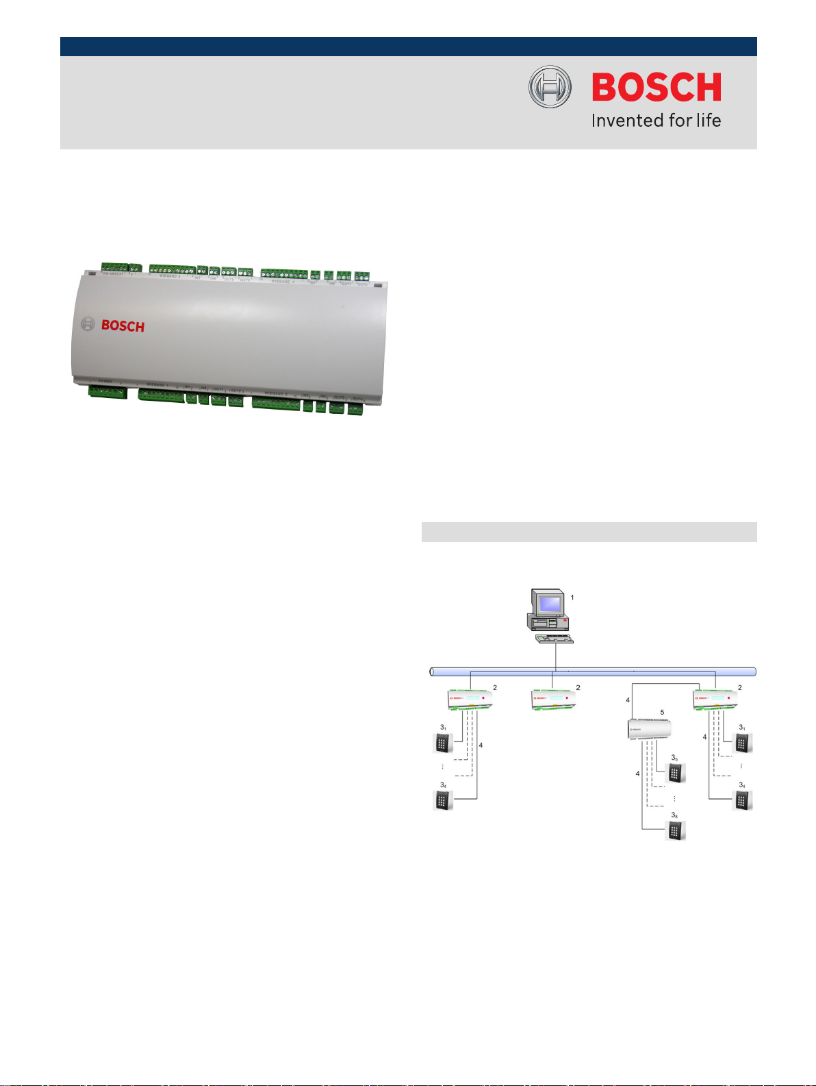
System Overview
The AMC2 4W-EXT is connected between the access
controller AMC2 4W and the various peripheral devices.
1 = Host
2 = AMC2 4W
3 = Card reader
4 = Communication and power supply
5 = AMC2 4W-EXT
www.boschsecurity.com
2 | AMC2 4W-EXT - Wiegand Extension Board
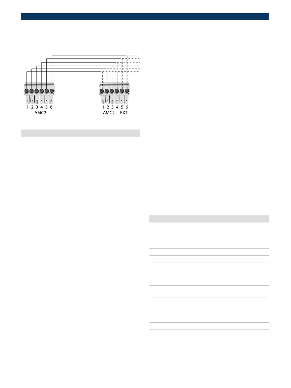
The AMC2 4W-EXT is connected to the AMC2 4W using the
RS-485 extension interface. This interface will also be used
to connect further extension modules.
Installation/Configuration Notes
The number of controllers in one system is limited to 200.
The using of AMC2 4W-EXT modules has no influence on this
limit, because it is an extension to an AMC2 4W and not a
controller.
Using Wiegand interfaces, up to eight peripheral devices
can be connected to each AMC2 4W. The interfaces are
point-to-point connections, meaning that only one reader
can be connected to one interface.
Power supply
An external power supply (10 to 30 V DC) for the AMC2 is
connected to the first (positive) and third pin (negative).
When using an uninterruptible power supply (UPS), the
relevant UPS output relay is connected to the pins
4 and 7 for alternating current (AC)
•
5 and 7 for the battery
•
6 and 7 for direct current (DC)
•
Otherwise, these pins will short-circuit.
Voltage equalization - grounding
Different grounds can be balanced via jumpers with
•
protective ground.
A line (shielding, potential equalization) with protective
•
ground must only be connected in one place.
For further instructions, please see the operating
•
manual.
Wiegand interface
The AMC2 4W-EXT has four interfaces to connect up to four
readers. The following definitions apply to the interface:
10 wire interface with shield
•
Max. cable length: 158 m (172.8 yd)
•
26 bit wiegand format
•
37 bit wiegand format
•
Default configuration:
1 = Reader Supply – 12V+
2 = Reader Supply – 0V
3 = Data 0
4 = Data 1
5 = Shield
6 = green LED
7 = red LED
8 = Beeper
9 = Hold
10 = Card Present
Contacts
Inputs
The analog inputs can be used as digital or analog contacts.
For analog use, resistance values can be specified to check
for cable breaks and short-circuits.
Relay outputs
The relay outputs offer the following functions:
The outputs can operate with potential free contacts for
•
external power supply (dry mode).
The outputs can operate using the internal voltage of
•
power supply (wet mode).
Only ohm resistive loads can be connected to the relay.
•
Inductive loads must be bypassed via recovery diodes.
•
These diodes (1N4004) are enclosed.
General instructions
All access equipment should be mounted within a
•
"secured area".
Detailed connection conditions are specified in the
•
operating manual!
After purchase, primary AC power must be carried out
•
by a licensed electrician.
Technical Specifications
Hardware 4 Wiegand reader interfaces
8 relay outputs - with ohm load:
- max. switching voltage: 30 V DC
- max. switching current: 1,25 A
8 analog inputs
Tamper switch
Temperature 0°C to +45°C (32° F to 113° F)
Power supply - 10 or 30 V DC, max. 60 VA
Available for external devices: 55 VA
- or via the AMC2
Protection
class
Housing Base: PPO (UL 94 V-0)
Color White
Dimensions WxHxD: 232 x 90 x 46 mm (9.13 x 3.54 x 1.81 in.)
Weight Approx. 0.4 kg (0.88 lb)
Type Rail mounting
IP 30
Upper: Polycarbonate (UL 94 V-0)
 Loading...