

Bosch 5412 Operating/safety Instructions Manual
iMPORTANT: iMPORTANT IMPORTANTE:
Read BeforeUsing Lireavantusage Leer antes de usar
Operating/Safetyinstructions
Consignesdefonctionnernent/s6curit6
instruccionesdefuncionarnientoyseguridad
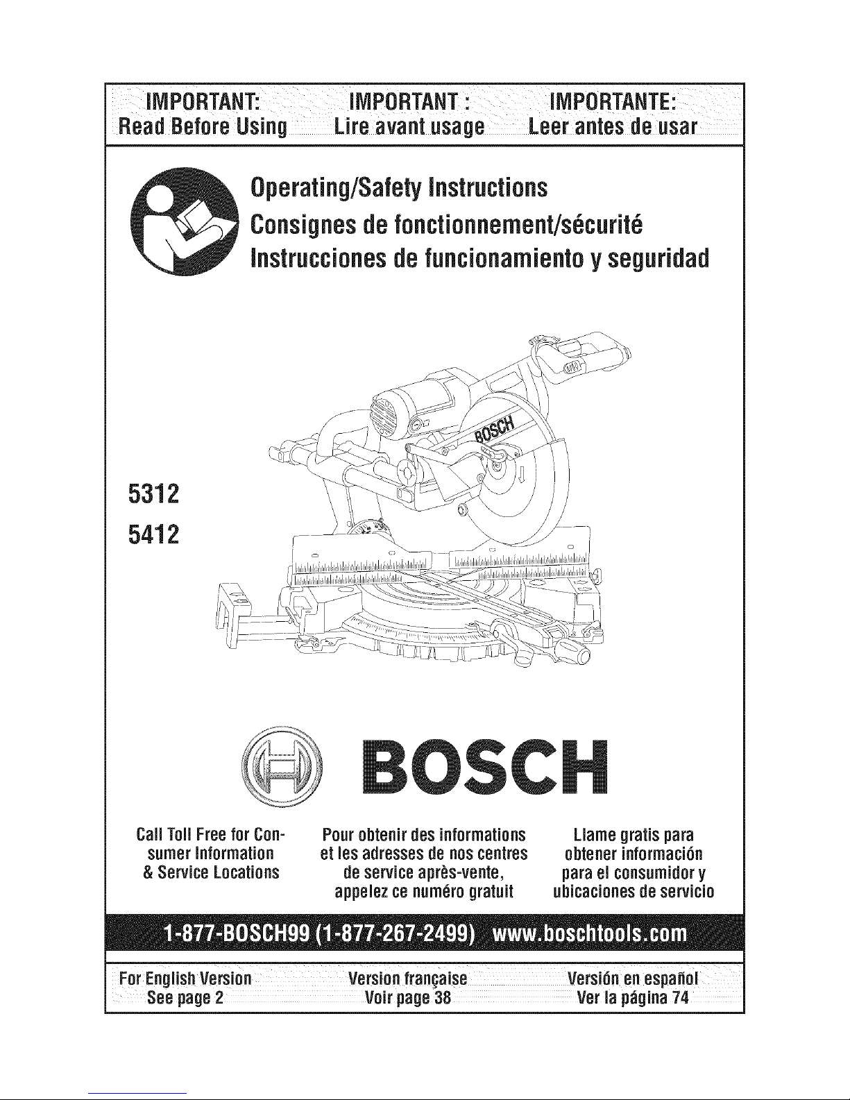
5312
5412
Call ToilFreeforCon-
sumerInformation
& Service Locations
Pourobtenir desinforrnations
et les adresses denoscentres
deserviceapr_s-vente,
appeJezce nurn_rogratuit
Llarnegratispara
obtener information
parael consurnidory
ubicaciones de servicio
For EnglishVersion Versionfran_aise Versi6nenes
Seepage2 Voir page38 Veria p_gina74
_ "READ ALL INSTRUCTIONS" -- Failure to follow the SAFETY RULES identified by
__ BULLET (o)symbol listed BELOW and other safety precautions, may result in serious
personal injury.
General Safety Rules For Bench Top Tools
Work Area • Do not abuse the cord. Never use the cord to
• Keep work area clean and well lit. Cluttered
benches and dark areas invite acdents.
• Do not operate power tools in explosive at-
mospheres, such as in the presence of flam-
mable liquids, gases or dust. Power tools
create sparks which may ignite the dust or fumes.
• Keep bystanders, children and visitors away
while operating a power tool. Distractions ca-
cause you to lose control.
• Store idle tools out of reach of children and
other untrained persons. Tools are danger-ous
in the hands of untrained users.
• Do not leave tool running unattended, turn
power off. Do not leave tool until it comes to
acomplete stop.
• MAKE WORKSHOP CHILDPROOF with pad
lock, master switches, or by removing starter
keys.
Electrical Safety
• Before plugging in the tool, be certain the out-
let voltage supplied is compatible with the
voltage marked on the nameplate within 10%.
An outlet voltage incompatible with that specified
on the nameplate can result in serious hazards
and damage to the tool.
• Double insulated tools are equipped with a po- .
larized plug (one blade is wider than the
other). This plug will fit in a polarized outlet
only one way. if the plug does not fit fully in
the outlet, reverse the plug. if it still does not
fit, contact a qualified electrician to install a "
polarized outlet. Do not change the plug in
any way. Double insulation eliminates the need
for the three wire grounded power cord and
grounded power supply.
• Avoid body contact with grounded surfaces
such as pipes, radiators, ranges and refriger-
ators. There is an increased risk of electric shock
if your body is grounded.
• Do not expose power tools to rain or wet con- "
ditions. Water entering a power tool will increase
the risk of electric shock.
"SAVE THESE
carry the tools or pull the plug from an outlet.
Keep cord away from heat, oil, sharp edges or
moving parts. Replace damaged cords imme-
diately. Damaged cords increase the risk of elec-
tric shock.
When operating a power tool outside, use an
outdoor extension cord marked "W-A" or "W".
These cords are rated for outdoor use and reduce
the risk of electric shock.
Personal Safety
• Stay alert, watch what you are doing and use
common sense when operating a power tool.
A moment of inattention or use of drugs, alcohol
or medication whileoperating power tools can be
dangerous.
• Dress properly. Do not wear loose clothing or
jewelry. Contain long hair. Keep your hair,
clothing and gloves away from moving parts.
Loose clothes, jewelry or longhair can be caught
in moving parts. Roll long sleeves above elbows.
Rubber gloves and non-skidfootwear are recom-
mended when working outdoors.
• Avoid accidental starting. Be sure switch is
"OFF" before plugging in. Carrying tools with
your finger on the switch or plugging intools that
have the switch "ON" invites accidents.
Remove adjusting keys or wrenches before
turning the tool "ON". A wrench ora key that is
left attached to a rotating part of the tool will be
thrown.
Do not overreach, keep proper footing and
balance at all times. Proper footing and balance
enables better control of the tool in unex-pected
situations.
Do not stand on tool or its stand. Serious injury
may occur if the tool is tipped or if the cutting tool
is accidentally contacted. Do not store materials
on or near the tool such that it is necessary to
stand on the tool or its stand to reachthem.
Use safety equipment. Always wear safety
goggles. Dust mask, safety shoes, hard hat or
hearing protection must be used for appropriate
INSTRUCTIONS"
-2-

conditions. Everyday eyeglasses only have
impact resistant lenses, they are NOT safety
glasses.
Tool Use and Care
• Use clamps or other practical way to secure
and support the wotkpiece to a stable plat-
form. Holding the work by hand or against your
body is unstable. Itallows forwork to shift,causes
binding of the tool and loss of control.
• Donot force tool. Usethe correct tool for your
application. The correct tool will do the job better
and safer at the rate for which it is designed. Do
not use the tool for purpose not intended - for ex-
ample; do not usethe miter sawfor slicing meats.
• Donot use tool if switch does not turn it "ON"
or "OFF". Any tool that cannot be controlled with
the switch is dangerous.
• Disconnect the plug from the power source
before making any adjustments or changing
accessories. Such preventive safety measures
reduce the riskof starting the tool accidentally.
• Keep cutting tools sharp and clean. Properly
maintained tools, with sharp cutting edges, are
less likely to bind and easier to control. When
mounting saw blades be certain that the arrow on
thblade matches the direction of the arrow marked
on the tool andthat the teeth are also pointing in
the same direction.
• Inspect guards before using a tool. Keep
guards in place. Check moving parts for bind-
ing or any other condition that may affect the
normal operation or safety features of the tool.
If damaged, have tool serviced before using
the tool. Many accidents are caused by poorly
maintained tools.
• Do not alter or misuse tool. Any alteration or
modification is a misuse and may result in serious
personal injury.
• The use of any other accessories not speci-
fied in this manual may create a hazard. Ac-
cessories that may besuitable forone type of tool,
may become hazardous when used on an inap-
propriate tool.
Service
• Tool service must be performed only by qual-
ified repair personnel. Service or maintenance
performed by unqualified personnel may result in
misplacing internal wires and components which
could cause serious hazard.
When servicing a tool, use only identical re-
placement parts. Follow instructions in the
Maintenance section of this manual. Use of
unauthorized parts or failure to follow Maintenance
Instructions may create a hazard.
Safety Rules For Miter Saws
• Use clamps to support wotkpiece whenever
possible, if supporting the workpiece by hand,
you must always keep hand outside of "No
Hand" area as marked with a symbol on the
base. Do not use this saw to cut pieces that
are too small to be securely clamped. Your
hand if placed inside the "No Hands"
region can easily slip or be pulled into the blade.
• Do not reach in back of the saw blade behind
the fence with either hand to hold
down or support the workpiece, remove wood
scraps, or for any other reason. The proximity
of the spinning saw blade to your hand may not
be obvious and you may be seriously injured.
• Never cross your hand over intended line of
cutting. Supporting the workpiece "cross handed"
i.e. holding the left side of the workpiece with your
right hand is very dangerous.
• Always disconnect the power cord from the
power source before making any adjustments
or attaching any accessories. You may unin-
tentionally start the saw, leading to serious per-
sonal injury.
• Miter saws are intended to cut wood or wood-
like products, they cannot be used with abra-
sive cutoff wheels for cutting ferrous material
such as bars, rods, studs, etc. However, if cut-
ting materials like aluminum or other non-fer-
rous metals, use only saw blades specifically
recommended for non ferrous metal cutting.
Cutting ferrous materials causes excessive spark-
ing and will damage the lower guard and will over-
load the motor.
(NOTE: Robert BoschTool Corporation does not
offer 12" metal cutting blades.)
Inspect your workpiece before cutting. If
wotkpiece is bowed or warped, clamp it with
the outside bowed face toward the fence. Al-
ways make certain that there is no gap be-
tween the workpiece, fence and table along
the line of the cut. Bent or warped workpieces
can twist or rock and may cause binding on the
spinning saw blade while cutting. Also, make sure
there are no nails or foreign objects in the work-
piece.
"SAVE THESE INSTRUCTIONS"
-3-
• Do not use the saw until the table isclear of all
tools, wood scraps, etc., except the work-
piece. Small debris or loose pieces of wood or
other objects that contact the revolving blade can
bethrown with high speed at the operator.
• Do not feed workpiece into the blade or cut
"freehand" in any way. Workpiece must be
stationary and clamped or braced by your
hand. Saw must be fed through the workpiece
smoothly and at a rate which will not overload the
saw's motor.
• Cut only one workpiece at a time. Multiple
workpieces cannot be adequately clamped or
braced and may bind on the blade or shift during
cutting.
• Be certain the miter saw ismounted or placed
on a level, firm work surface before using. A
leveland firm work surface reduces the riskof the
miter saw becoming unstable.
• Plan your work. Provide adequate support
accessories such as tables, saw horses, table
extension, etc. for workpieces wider or longer
than the table top (see page 20). Workpieces
longer or wider than the miter saw table can tip if
notsecurely supported. If the cutoffpiece or work-
piece tips it can lift the lower guard or be thrown
bythe spinning blade.
• Do not use another person as a substitute for
a table extension or as additional support. Un-
stable support for the workpiece can cause the
blade to bind or the workpiece to shift
during the cutting operation pulling you and the
helper into the spinning blade.
• The cutoff piece must not be jammed against
or pressured by any other means against the
spinning saw blade. Ifconfined, i.e.using length
stops, it could get wedged against the blade and
thrown violently.
• Always use a clamp or a fixture designed to
properly support round material such as
dowel rods, or tubing. Rods have atendency to
rollwhile beingcut, causingthe blade to"bite" and
pullthe work withyour hand into the blade.
• When cutting irregularly shaped work-pieces,
plan your work so itwill not slip and pinch the
blade and be torn from your hand.
A piece of molding, for example, must liefiat or be
held by a fixture or jig that will not let it twist, rock
or slip while being cut.
• Let the blade reach full speed before contact-
ing the workpiece. This will help avoid thrown
workpieces.
"SAVE THESE
• If the workpiece or blade becomes jammed or
bogged down, turn miter saw "OFF" by releas-
ing switch. Wait for all moving parts to stop
and unplug the miter saw, then work to free
the jammed material. Continued sawing with
jammed workpiece could cause loss of control or
damage to miter saw.
• Braking action of the saw causes the saw
head to jerk downward. Be ready for this reac-
tion when making an incomplete cut or when re-
leasing the switch before the head is completely
in the down position.
• After finishing the cut, release the switch, hold
the saw arm down and wait for blade to stop
before removing work or cutoff piece, if blade
does not stop within five (5) seconds, unplug
the saw and follow the instructions in the
Troubleshooting section. REACHING WITH
YOUR HAND UNDER A COASTING BLADE IS
DANGEROUS!
• There are additional safety instructions for
particular operations of the saw in the operat-
ing section. Read the rest of the man-ual for
safe operation.
• For slide action cutting, first PULL saw head
assembly away from the fence, until blade
clears the workpiece or to its maximum exten-
sion if blade cannot clear the workpiece. Make
certain the clamp does not interfere with the
guard and head assembly.
Second, turn saw "ON" and lower the saw to
the table. Then PUSH saw through the work-
piece. Release the switch and wait for the
blade to completely stop before raising the
head assembly and removing the workpiece.
Never "pullcut" since blade may climb the work-
piece causing KICKBACK.
• For chop action cutting, slide the head as-
sembly to the rear as far as it will go and
tighten slide lock knob. Then turn the saw
"ON" and lower the head assembly to make
the cut. Release the switch and wait for the
blade to completely stop before raising the
head assembly and removing the workpiece.
Failure to tighten the slide lock knob can cause
the blade to suddenly climb up on the top of the
workpiece and force itself toward you.
• Do not allow familiarity gained from frequent
use of your miter saw to become common-
place. Always remember that a careless fraction
of a second is sufficient to inflict severe injury.
INSTRUCTIONS"
-4-

_ READ ALL INSTRUCTIONS" -- Failure to follow the SAFETY RULES identified by
BULLET (o)symbol listed BELOW and other safety precautions, may result in serious per-
sonal injury.
• THINK SAFETY! SAFETY IS A COMBINATION
OF OPERATOR'S COMMON SENSE, KNOWL-
EDGE OF THE SAFETY AND OPERATING IN-
STRUCTIONS AND ALERTNESS AT ALL TIMES
WHEN THE MITER SAW IS BEING USED.
THE WARNINGS SHOWN
BELOW CAN BE FOUND ON
YOUR TOOL. THESE WARNINGS ARE ONLY A
CONDENSED FORM OF THE MORE DETAILED
SAFETY RULES AND PRECAUTIONS THAT AP-
PEAR iN YOUR OWNER'S MANUAL. THEY
SERVE AS A REMINDER OF ALL SAFETY
RULES NEEDED FOR SAFE OPERATION OF
THIS MITERSAW.
Some dust created by power
sanding, sawing, grinding,
drilling, and other construction activities con-
tains chemicals known to cause cancer, birth
defects or other reproductive harm. Some ex-
amples of these chemicals are:
• Lead from lead-based paints,
• Crystalline silica from bricks andcement and other
masonry products, and
•Arsenic and chromium from chemically treated
lumber.
Your risk from these exposures varies, depending
on how often you do this type of work. To reduce
your exposure to these chemicals: work in a well
ventilated area, and work with approved safety
equipment, such as those dust masks that are spe-
cially designed to filterout microscopic particles.
DESIGNATED DANGER ZONE. AVOID POSiTiONING HANDS, FINGERS
OR ARMSIN THE AREA DESIGNATED BY THIS SYMBOL.
"SAVE THESE INSTRUCTIONS"
"5"
_ READ ALL INSTRUCTIONS" -- Failure to follow the SAFETY RULES identified by
BULLET (,) symbol listed BELOW and other safety precautions, may result in serious
personal injury.
Double insulated Tools
Double insulation [] is a design concept used in
electric power tools which eliminates the need for
the three wire grounded power cord and grounded
power supply system. It is a recognized and ap-
proved system by Underwriter's Laboratories, CSA
and Federal OSHA authorities.
• Servicing of a tool with double insulation requires
care and knowledge of the system and should be
performed only bya qualified service technician.
•WHEN SERVICING, USE ONLY IDENTICAL RE-
PLACEMENT PARTS.
• POLARIZED PLUGS. To reduce the risk of elec-
trical shock, your tool is equipped with a polarized
plug (one blade is wider than the other), this plug
will fit inapolarized outlet only one way. Ifthe plug
does not fit fully in the outlet, reverse the plug. If it
still does not fit, contact a qualified electrician to in-
stall the proper outlet. To reduce the risk of elec-
trical shock, do not change the plug inany way.
Extension Cords
• Replace damaged cords immediately. Use of
damaged cords can shock, burn or electrocute.
• Ifan extension cord is necessary, a cordwith ade-
quate size conductors should be used to prevent
excessive voltage drop, loss of power or overheat-
ing. The table shows the correct size to use, de-
pending on cord length and nameplate amperage
rating of tool. If in doubt, use the next heavier
gauge. Always use U.L.and CSA listed extension
cords.
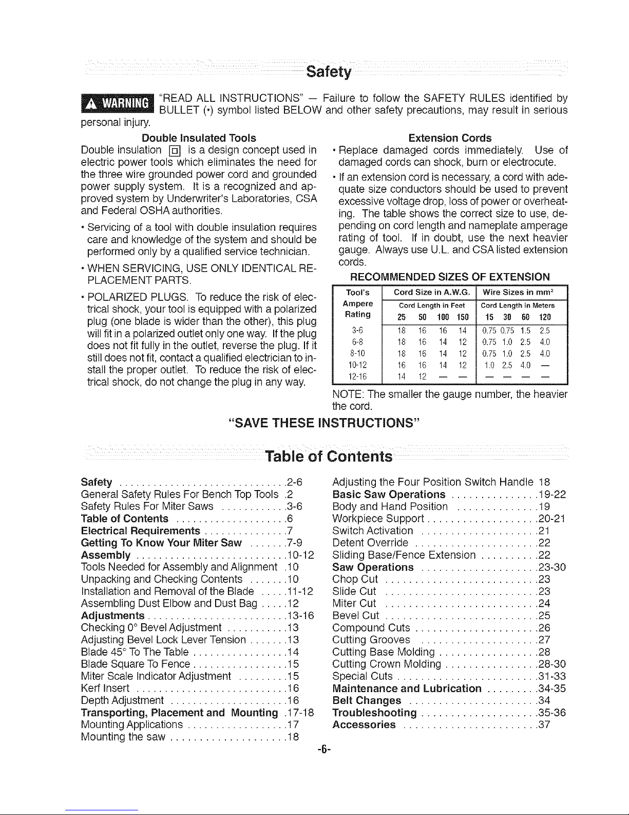
RECOMMENDED SIZES
Tool's Cord Size in A.W.G,
Ampere Cord LerBgth in Feet
Rating 25 50 188 150
3-6 18 16 16 14
6-8 18 16 14 12
8-10 18 16 14 12
10-12 16 16 14 12
12-16 14 12
)F EXTENSION
Wire Sizes in mm 2
Cord Length in Meters
15 30 60 120
0.75 0.75 1.5 2.5
0.75 1.0 2.5 4.0
0.75 1.0 2.5 4.0
1.0 2.5 4.0 --
NOTE: The smaller the gauge number, the heavier
the cord.
"SAVE THESE INSTRUCTIONS"
Safety .............................. 2-6
General Safety Rules For Bench TopTools .2
Safety Rules ForMiter Saws ............ 3-6
Table of Contents .................... 6
Electrical Requirements ............... 7
Getting To Know Your Miter Saw ....... 7-9
Assembly ........................... 10-12
Tools Needed forAssembly and Alignment .10
Unpacking and Checking Contents ....... 10
Installation and Removal ofthe Blade ..... 11-12
Assembling Dust Elbow and Dust Bag ..... 12
Adjustments ......................... 13-16
Checking 0° BevelAdjustment ........... 13
Adjusting Bevel Lock Lever Tension ....... 13
Blade 45° To The Table ................. 14
Blade Square To Fence ................. 15
Miter Scale Indicator Adjustment ......... 15
Kerr Insert ........................... 16
DepthAdjustment ..................... 16
Transporting, Placement and Mounting .17-18
Mounting Applications .................. 17
Mounting the saw .................... 18
Adjusting the Four Position Switch Handle 18
Basic Saw Operations ............... 19-22
Body and Hand Position .............. 19
Workpiece Support ................... 20-21
Switch Activation .................... 21
Detent Override ..................... 22
Sliding Base/Fence Extension .......... 22
Saw Operations .................... 23-30
Chop Cut .......................... 23
Slide Cut .......................... 23
Miter Cut .......................... 24
Bevel Cut .......................... 25
Compound Cuts ..................... 26
Cutting Grooves .................... 27
Cutting Base Molding ................. 28
Cutting Crown Molding ................ 28-30
Special Cuts ........................ 31-33
Maintenance and Lubrication ......... 34-35
Belt Changes ...................... 34
Troubleshooting .................... 35-36
Accessories ....................... 37
-6-
1.Connect this saw to a 120V, 15-amp branch cir-
cuit with a 15-amp time delay fuse or circuit
breaker. Using the wrong size fuse can damage
the motor.
2. Fuses may "blow" or circuitbreakers may trip fre-
quently if motor is overloaded. Overloading can
occur if you feed the blade into the workpiece too
rapidly or start and stop too often ina short time.
3. Most motor troubles may betraced to loose or in-
correct connections, overload, low voltage (such
as small size wire in the supply circuit or too
overly long supply circuit wire). Always check the
connections, the load and the supply circuit when-
ever motor does not work well.
Electric Brake
Your saw is equipped with an automatic electric
brake which is designed to stop the blade from spin-
ning in about five (5) seconds after you release the
trigger switch. It is useful when making certain cuts
in wood where a coasting blade would result in a
wide, imprecise cut.
When electricalpower is lostdue to
__ blown fuse or other causes, the
motorwillgradually slow down and the brakingaction
isinitiated ONLY by the release ofthe trigger switch.
The electric blade brake of your mitersaw has been
designed for highest degree of reliability, but unex-
pected circumstances such as contamination on the
commutator and brushes or failure of motor's com-
ponents can cause the brake not to activate. If this
condition occurs, turn the saw "ON" and "OFF" four
to five times without contacting the workpiece. Ifthe
tool operates but the brake does not consistently
stop the blade in about five (5) seconds, DO NOT
use saw and have it serviced immediately.
The brakeaction ofthis saw is not
intended as a safety feature. Re-
member to let the saw blade come to a complete
stop before raisingthe blade from the workpiece. As
always the guard system is your best protection
against unintentional contact with a spinning saw
blade. NEVER wedge open or defeat the closing
action ofthe lowerguard.
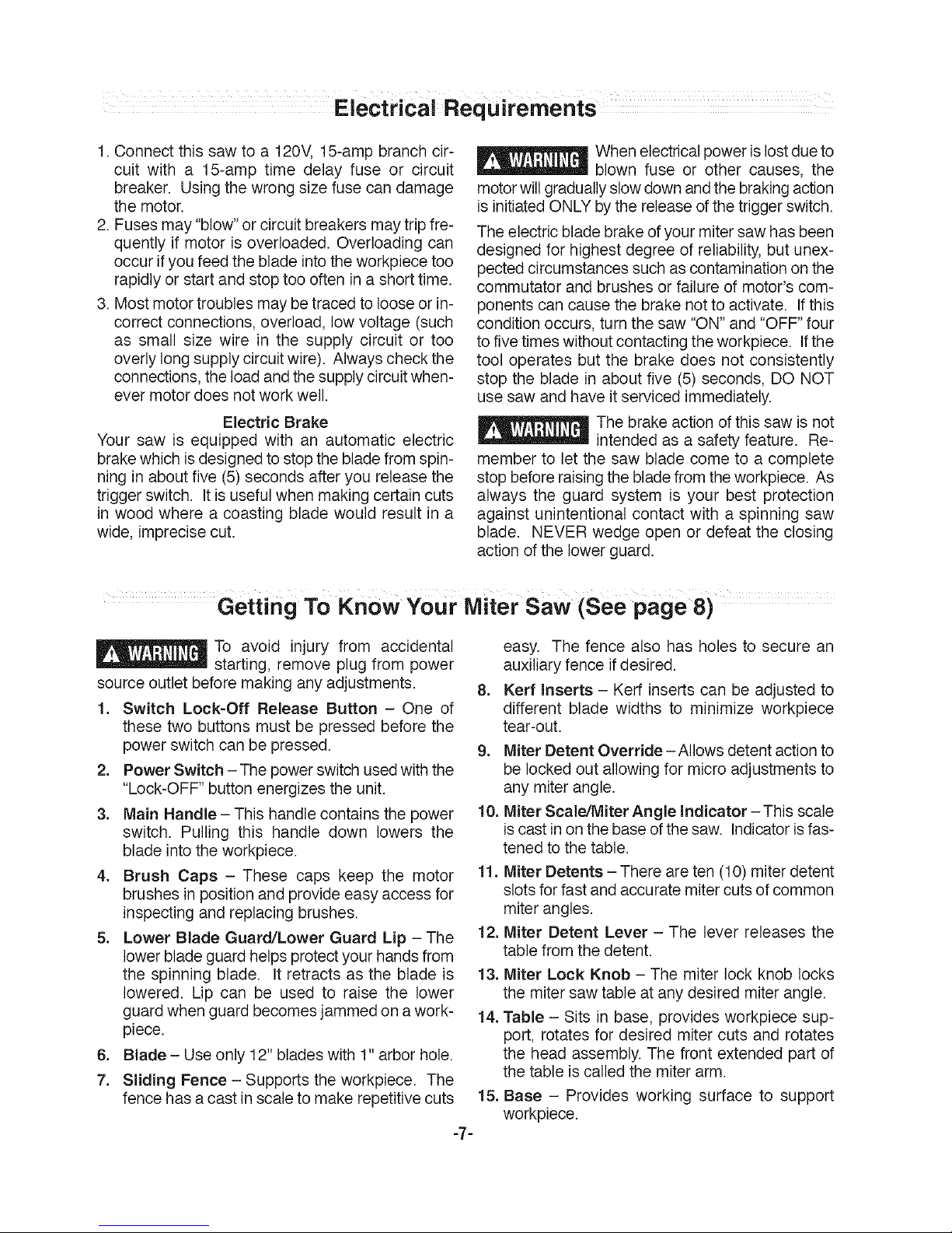
Getting To Know Your IVliter Saw (See page 8)
To avoid injury from accidental
-- starting, remove plug from power
source outlet before making any adjustments.
1. Switch Lock-Off Release Button - One of
these two buttons must be pressed before the
power switch can be pressed.
2. Power Switch - The power switch usedwith the
"Lock-OFF" button energizes the unit.
3. Main Handle- This handle contains the power
switch. Pulling this handle down lowers the
blade into the workpiece.
4. Brush Caps - These caps keep the motor
brushes in position and provide easy access for
inspecting and replacing brushes.
5. Lower Blade Guard/Lower Guard Lip - The
lower blade guard helps protectyour hands from
the spinning blade. It retracts as the blade is
lowered. Lip can be used to raise the lower
guard when guard becomes jammed on a work-
piece.
6. Blade- Use only 12" blades with 1" arbor hole.
7. Sliding Fence- Supports the workpiece. The
fence has a cast inscale to make repetitive cuts
-7-
easy. The fence also has holes to secure an
auxiliary fence if desired.
8. Kerr Inserts - Kerf inserts can be adjusted to
different blade widths to minimize workpiece
tear-out.
9. Miter Detent Override -Allows detent action to
be locked out allowing for micro adjustments to
any miter angle.
10. Miter Scale,Jilter Angle indicator - This scale
is castin on the base ofthe saw. Indicatorisfas-
tened to the table.
11. Miter Detents - There are ten (10) miter detent
slots forfast and accurate miter cuts of common
miter angles.
12. Miter Detent Lever - The lever releases the
table from the detent.
13. Miter Lock Knob - The miter lock knob locks
the miter saw table at any desired miter angle.
14. Table - Sits in base, provides workpiece sup-
port, rotates for desired miter cuts and rotates
the head assembly. The front extended part of
the table is called the miter arm.
15. Base - Provides working surface to support
workpiece.
4 20 41
1
1 3
28
17
18 16
I
15 14 11
10 11 11 12
16. Tool Mounting Pads - The four corners of the
saw provide areas to clamp, bolt or nailthe saw
to a fiat work surface.
17. Sliding Base Extensions - These extensions
provide extra workpiece support and are espe-
cially useful when cutting long workpieces.
18. Base Extension Clamping Levers - These
levers lock the base extensions at the desired
positions.
19. Length Stop (Model 5412 only) - For repetitive
cuts of the same length. Can be moved to left
side, if desired.
20. Dust Port - The dust port can accommodate
the dust chute and dust bag or a 1-1/4" vacuum
hose hookup.
21. Bevel Lock Lever - The front-positioned bevel
lock lever locks the head assembly at the de-
sired bevel angle.
-8-
22. Bevel Range Selector Knob- Allows selection
of the bevel range, 0°to 45° left, 0° to 45° right,
and complete range of 47° left to 47° right.
23. Slide Rail Lock Knob -The slide rail lock knob
locks the slide rails when you are not making
slidecuts and when you aretransporting the saw.
24. Slide Rails - Guide the head assembly when
making slide cuts.
25. Clamp Position Holes - There are two (2)
holes (not shown) behind the fence for placing
the clamp.
26. Quick Action Clamp (Model 5412 only) - Pro-
vides fast clamping of workpiece.
27. Workpiece Clamp (Model 5312 only) - Pro-
vides fast clamping of workpiece.
28. Cord Wrap - Allows you to easily wrap up the
cord so it's out of the way when transporting or
storing.
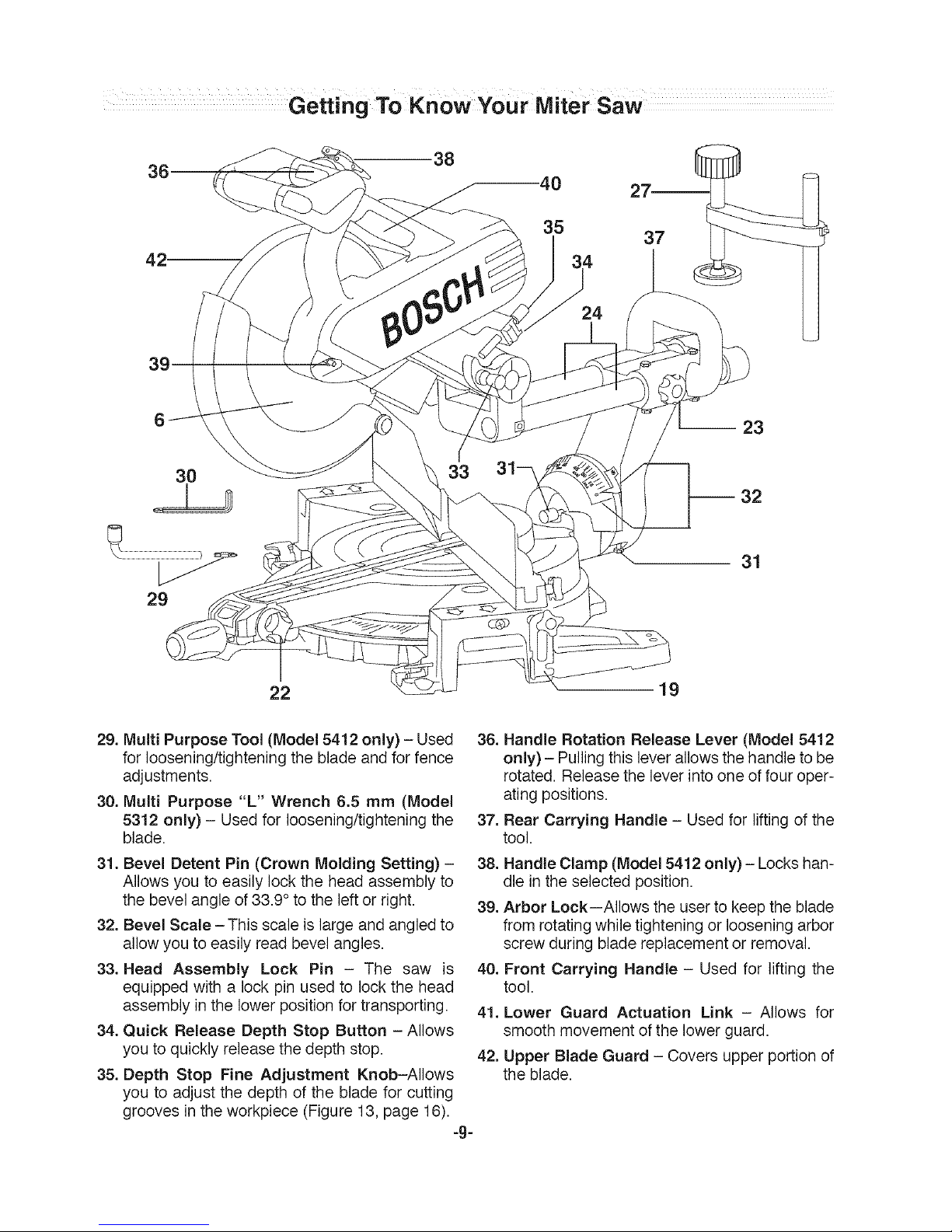
38
30
29
31
22 19
29. Multi Purpose Tool (Model 5412 only) - Used
for loosening/tightening the blade and for fence
adjustments.
30. Multi Purpose "L" Wrench 6.5 mm (Model
5312 only) - Used for loosening/tightening the
blade.
31. Bevel Detent Pin (Crown Molding Setting) -
Allows you to easily lock the head assembly to
the bevel angle of 33.9 ° to the left or right.
32, Bevel Scale -This scale is large and angled to
allow you to easily read bevel angles.
33. Head Assembly Lock Pin - The saw is
equipped with a lock pin used to lock the head
assembly in the lower position for transporting.
34. Quick Release Depth Stop Button - Allows
you to quickly release the depth stop.
35. Depth Stop Fine Adjustment Knob-Allows
you to adjust the depth of the blade for cutting
grooves in the workpiece (Figure 13, page 16).
-g-
36.
37.
38.
39.
Handle Rotation Release Lever (Model 5412
only) - Pullingthis leverallows the handle to be
rotated. Release the lever into one of four oper-
ating positions.
Rear Carrying Handle - Used for lifting of the
tool.
Handle Clamp (Model 5412 only) - Locks han-
dle in the selected position.
Arbor Lock--Allows the userto keepthe blade
from rotating while tightening or loosening arbor
screw during blade replacement or removal.
40. Front Carrying Handle - Used for lifting the
tool.
41. Lower Guard Actuation Link - Allows for
smooth movement of the lower guard.
42, Upper Blade Guard - Covers upper portion of
the blade.
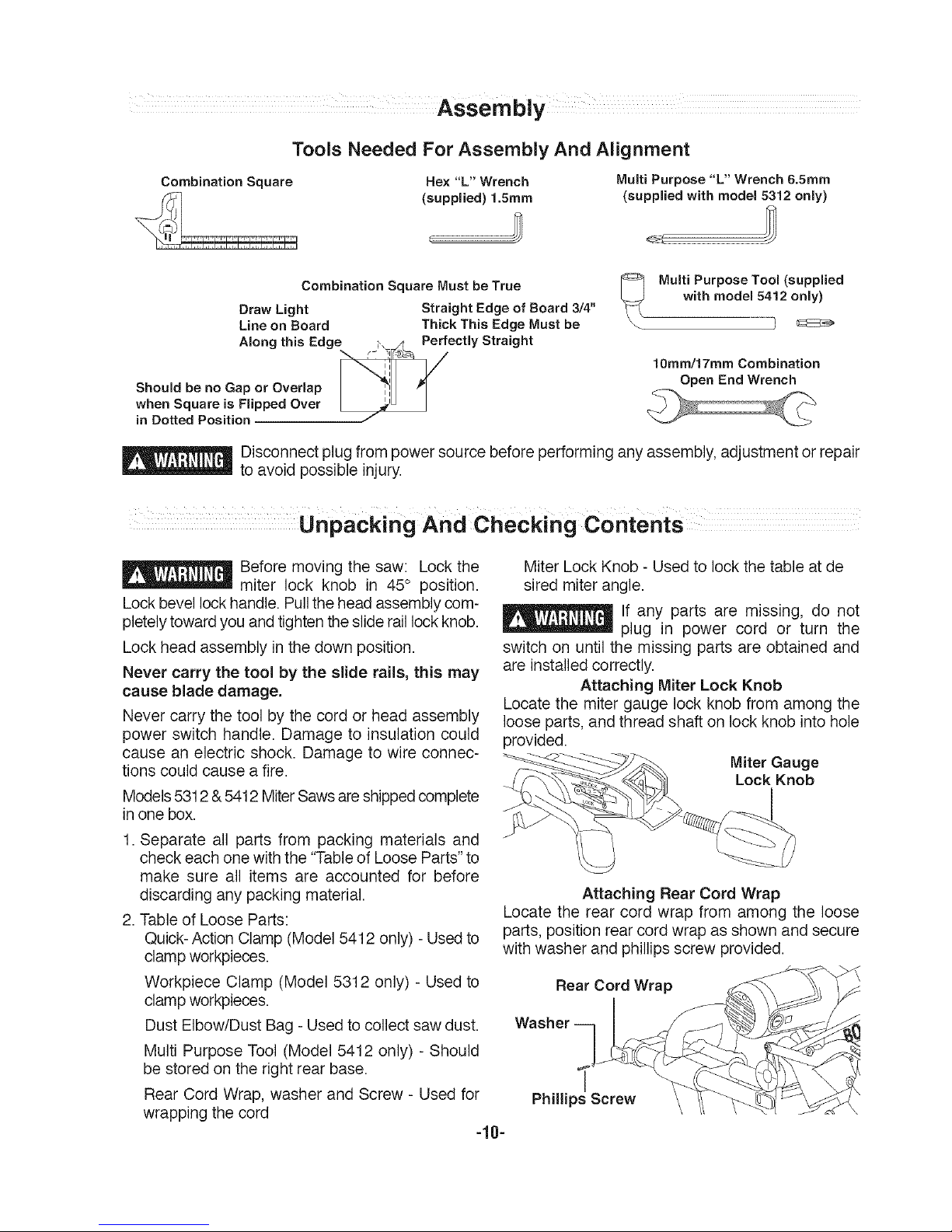
ToolsNeededForAssembly And Alignment
Combination Square Hex "L" Wrench Multi Purpose "L" Wrench 6.5ram
(suppmied) 1.5ram (suppmied with modem 5312 onmy)
Combination Square Must be True
Draw Light Straight Edge of Board 3/4"
Line on Board Thick This Edge Must be
Amongthis Edge _" ,r_ Perfectmy Straight
..oo,00oooo 0o ovo ,a0
when Square is Flipped Over I _'_i
in Dotted Position J
Multi Purpose Tool (supplied
with model 5412 only)
10mm/17mm Combination
Open End Wrench
_ Disconnect plug from power source before performing any assembly, adjustment or repair
__ to avoid possible injury.
Unpacking And Checking Contents
_ efore moving the saw: Lock the
miter lock knob in 45° position.
Lockbevel lock handle. Pull the head assembly com-
pletely toward you andtighten the slideraillock knob.
Lock head assembly in the down position.
Never carry the tool by the slide rails, this may
cause blade damage.
Never carry the tool by the cord or head assembly
power switch handle. Damage to insulation could
cause an electric shock. Damage to wire connec-
tions could cause a fire.
Models5312 & 5412MiterSawsare shippedcomplete
in one box.
1. Separate all parts from packing materials and
check each one with the "Tableof Loose Parts"to
make sure all items are accounted for before
discarding any packing material.
2. Table of Loose Parts:
Quick-Action Clamp (Model 5412 only) - Usedto
clampworkpieces.
Workpiece Clamp (Model 5312 only) - Used to
clampworkpieces.
Dust Elbow/Dust Bag- Used to collect saw dust.
Multi Purpose Tool (Model 5412 only) - Should
be stored onthe right rear base.
Rear Cord Wrap, washer and Screw - Used for
wrapping the cord
-10-
Miter Lock Knob - Used to lock the table at de
sired miter angle.
lf any parts are missing, do not
__ plug in power cord or turn the
switch on until the missing parts are obtained and
are installed correctly.
Attaching Miter Lock Knob
Locate the miter gauge lock knob from among the
loose parts, and thread shaft on lock knob into hole
provided.
Miter Gauge
Lock Knob
Attaching Rear Cord Wrap
Locate the rear cord wrap from among the loose
parts, position rear cord wrap as shown and secure
with washer and phillips screw provided.
Rear Cord Wrap
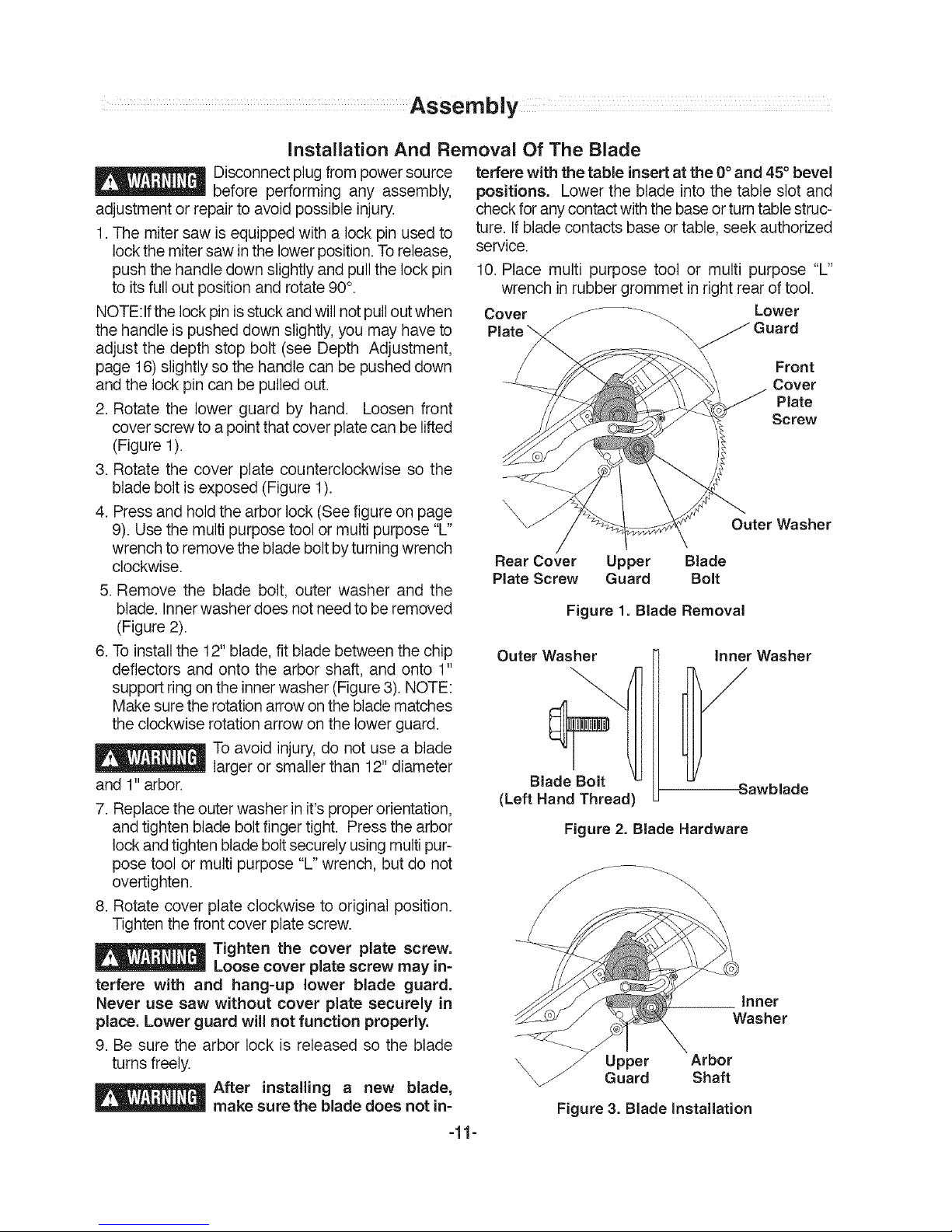
installation And Removal Of The Blade
_ isconnectplug from powersource
before performing any assembly,
adjustment or repair to avoid possible injury.
1.The mitersaw is equipped witha lock pin used to
lock the mitersaw inthe lower position.Torelease,
pushthe handle down slightly and pullthe lock pin
to its full out position and rotate 90°.
NOTE:Ifthe lock pinisstuckand will not pullout when
the handle is pushed downslightly,you may have to
adjust the depth stop bolt (see Depth Adjustment,
page 16)slightly so the handlecan be pusheddown
and the lock pin can be pulled out.
2. Rotate the lower guard by hand. Loosen front
cover screwto a point that cover plate can be lifted
(Figure 1).
3. Rotate the cover plate counterclockwise so the
blade bolt is exposed (Figure 1).
4. Pressand holdthe arbor lock (Seefigure on page
9). Use the multi purpose tool or multi purpose "L"
wrench toremove the blade boltby turningwrench
clockwise.
5. Remove the blade bolt, outer washer and the
blade. Inner washer does not needto be removed
(Figure2).
6. To installthe 12" blade, fit blade between the chip
deflectors and onto the arbor shaft, and onto 1"
support ringon the innerwasher (Figure 3).NOTE:
Make sure the rotation arrowon the bladematches
the clockwise rotation arrow on the lower guard.
Toavoid injury,do not use a blade
largeror smaller than 12" diameter
and 1" arbor.
7. Replacethe outerwasher in it's proper orientation,
andtighten blade boltfinger tight. Press the arbor
lock and tighten bladeboltsecurelyusing multipur-
pose tool or multi purpose "L" wrench, but do not
overtighten.
8. Rotate cover plate clockwise to original position.
Tighten the front cover platescrew.
_ Tighten the cover plate screw.
Loosecover plate screw may in-
terfere with and hang-up lower blade guard.
Never use saw without cover plate securely in
place. Lower guard will not function properly.
9. Be sure the arbor lock is released so the blade
turns freely.
_ After installing a new blade,
make sure the blade does not in-
-11-
terfere with the table insertat the 0° and 45° bevel
positions, Lower the blade into the table slot and
checkfor any contactwiththe baseor turntable struc-
ture. Ifblade contacts base ortable, seek authorized
service.
10. Place multi purpose tool or multi purpose "L"
wrench inrubber grommet in rightrear oftool.
Lower
Cover _ ..... _"_-,, Guard
\
Front
Cover
Plate
Screw
Outer Washer
Rear Cover Upper Blade
Plate Screw Guard Bolt
Figure 1. Blade Removal
Outer Washer
Blade Bolt
(Left Hand Thread
Inner Washer
Sawblade
Figure 2. Blade Hardware
\
Inner
Washer
Upper Arbor
Guard Shaft
Figure 3. Blade Installation
Assembly
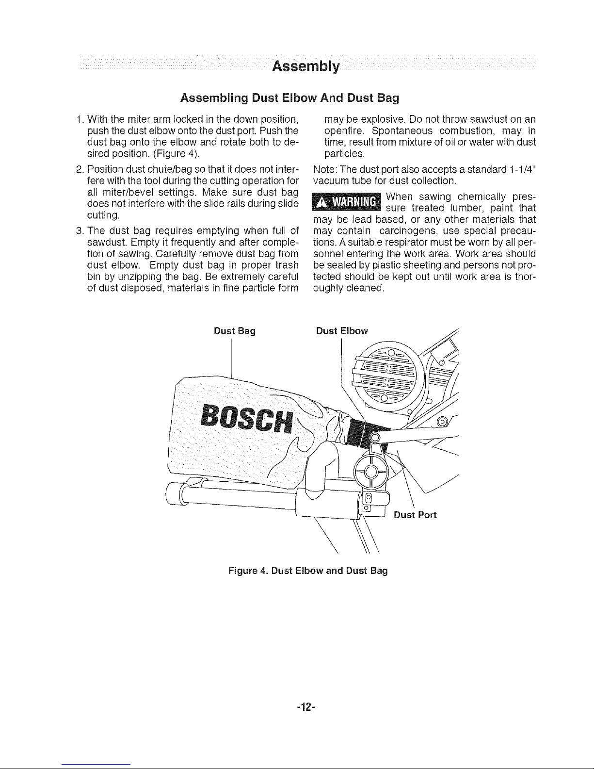
Assembling Dust Elbow And Dust Bag
1. With the miter arm locked in the down position,
pushthe dust elbow onto the dust port. Push the
dust bag onto the elbow and rotate both to de-
sired position. (Figure 4).
2. Position dust chute/bag sothat it does not inter-
fere with the tool during the cutting operation for
all miter/bevel settings. Make sure dust bag
does not interfere with the slide rails during slide
cutting.
3. The dust bag requires emptying when full of
sawdust. Empty it frequently and after comple-
tion of sawing. Carefully remove dust bag from
dust elbow. Empty dust bag in proper trash
bin by unzipping the bag. Be extremely careful
of dust disposed, materials in fine particle form
may be explosive. Do not throw sawdust on an
openfire. Spontaneous combustion, may in
time, result from mixture of oil or water with dust
particles.
Note: The dust port also accepts a standard 1-1/4"
vacuum tube for dust collection.
When sawing chemically pres-
sure treated lumber, paint that
may be lead based, or any other materials that
may contain carcinogens, use special precau-
tions. A suitable respirator must be worn byall per-
sonnel entering the work area. Work area should
be sealed by plastic sheeting and persons not pro-
tected should be kept out until work area is thor-
oughly cleaned.
Dust Bag
Dust Elbow
Dust Port
Figure 4. Dust Elbow and Dust Bag
-12-
Disconnect plug from power
source before performing any as-
sembly, adjustment or repairto avoid possible injury.
NOTE: Your miter saw was completely adjusted at
the factory. However, during shipment, slight mis-
alignment may have occurred. Check the following
settings and adjust if necessary prior to using this
miter saw.
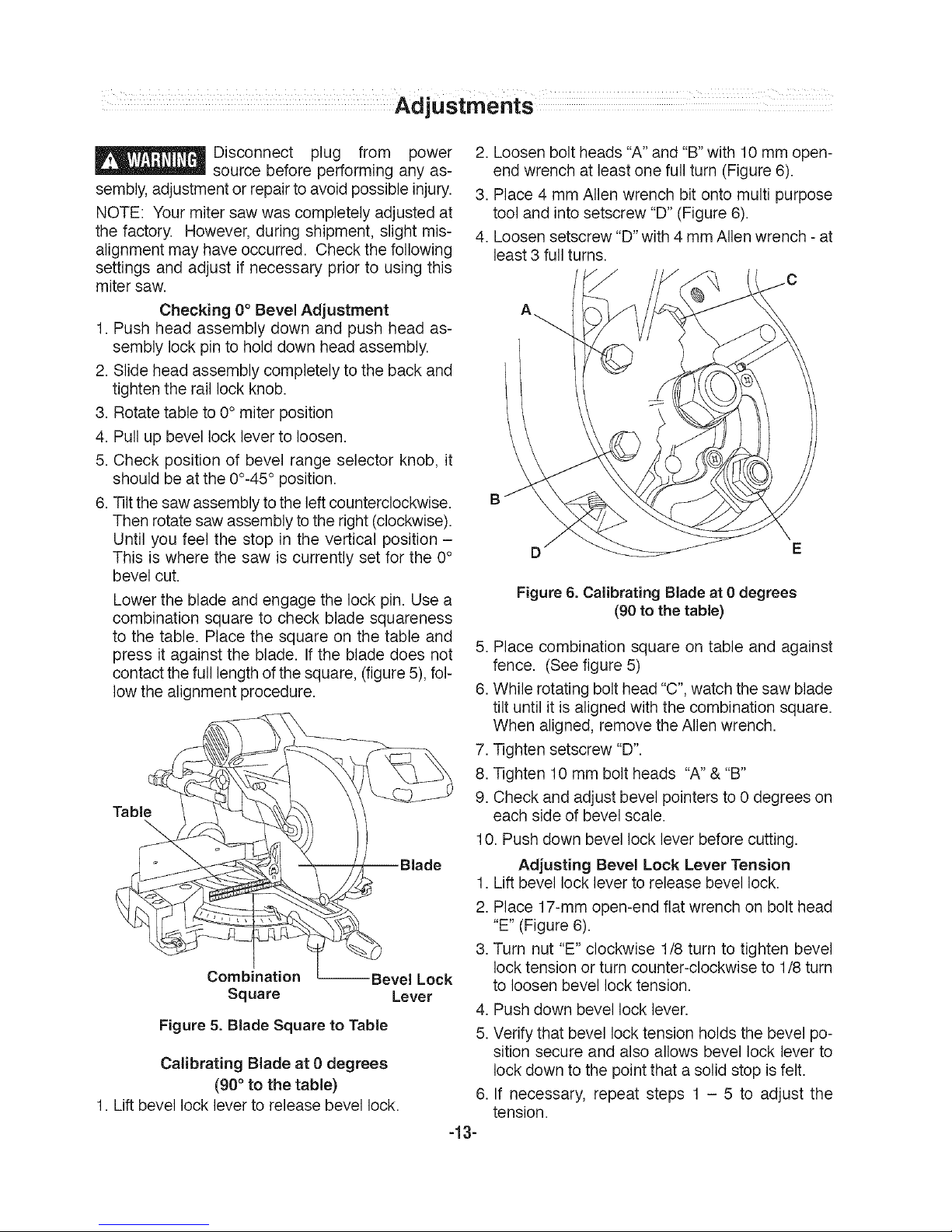
Checking 0°Bevel Adjustment
1. Push head assembly down and push head as-
sembly lock pin to hold down head assembly.
2. Slide head assembly completely to the back and
tighten the rail lock knob.
3. Rotate table to 0° miter position
4. Pull up bevel lock lever to loosen.
5. Check position of bevel range selector knob, it
should be at the 00-45° position.
6. Tiltthe saw assembly to the left counterclockwise.
Then rotatesaw assembly to the right(clockwise).
Until you feel the stop in the vertical position -
This is where the saw is currently set for the 0°
bevel cut.
Lower the blade and engage the lock pin. Use a
combination square to check blade squareness
to the table. Place the square on the table and
press it against the blade. If the blade does not
contact the full length of the square, (figure5), fol-
low the alignment procedure.
Table
Combination --Bevel Lock
Square Lever
Figure 5. Blade Square to Table
Calibrating Blade at 0 degrees
(90 ° to the table)
1. Lift bevel lock lever to release bevel lock.
2. Loosen bolt heads "A" and "B" with 10 mm open-
end wrench at least one full turn (Figure6).
3. Place 4 mm Alien wrench bit onto multi purpose
tool and into setscrew "D" (Figure 6).
4. Loosen setscrew "D" with 4 mm Alien wrench -at
least 3 full turns.
D
Figure 6. Calibrating Blade at 0 degrees
(90 to the table)
5. Place combination square on table and against
fence. (See figure 5)
6. While rotating bolt head "C",watch thesaw blade
tilt until it is aligned with the combination square.
When aligned, remove the Allen wrench.
7. Tighten setscrew "D".
8. Tighten 10 mm bolt heads "A" &"B"
9. Check and adjust bevel pointers to 0 degrees on
each side of bevel scale.
10. Push down bevel lock lever before cutting.
Adjusting Bevel Lock Lever Tension
1. Lift bevel lock lever to release bevel lock.
2. Place 17-mm open-end fiat wrench onbolt head
"E" (Figure 6).
3. Turn nut "E" clockwise 1/8 turn to tighten bevel
lock tension or turn counter-clockwise to 1/8 turn
to loosen bevel lock tension.
4. Push down bevel lock lever.
5. Verify that bevel locktension holdsthe bevel po-
sition secure and also allows bevel lock lever to
lock down to the pointthat a solid stop is felt.
If necessary, repeat steps 1 - 5 to adjust the
tension.
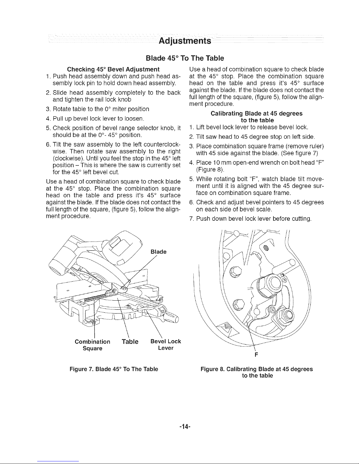
Blade 45° To The Table
Checking 45° Bevel Adjustment
1. Push head assembly down and push head as-
sembly lock pin to hold down head assembly.
2. Slide head assembly completely to the back
and tighten the rail lock knob
3. Rotate table to the 0° miter position
4. Pull up bevel lock lever to loosen.
5. Check position of bevel range selector knob, it
should be at the 0°- 45° position.
6. Tilt the saw assembly to the left counterclock-
wise. Then rotate saw assembly to the right
(clockwise). Untilyou feel the stop in the 45° left
position - This is where the saw is currently set
for the 45° left bevel cut.
Use a head of combination square to check blade
at the 45° stop. Place the combination square
head on the table and press it's 45° surface
against the blade. Ifthe blade does not contact the
full length of the square, (figure 5), follow the align-
ment procedure.
Use a head of combination square to check blade
at the 45° stop. Place the combination square
head on the table and press it's 45° surface
against the blade. Ifthe blade does not contact the
full length of the square, (figure 5), follow the align-
ment procedure.
Calibrating Blade at 45 degrees
to the table
1. Lift bevel lock lever to release bevel lock.
2. Tilt saw head to 45 degree stop on left side.
3. Place combination square frame (remove ruler)
with 45 side against the blade. (See figure 7)
4. Place 10 mm open-end wrench on bolt head "F"
(Figure 8).
5. While rotating bolt "F", watch blade tilt move-
ment until it is aligned with the 45 degree sur-
face on combination square frame.
6. Check and adjust bevel pointers to 45 degrees
on each side of bevel scale.
7. Push down bevel lock lever before cutting.
Blade
Combination Table Bevel Lock
Square Lever
Figure 7. Blade 45° To The Table Figure 8. Calibrating Blade at 45 degrees
to the table
-14-
Adjustments
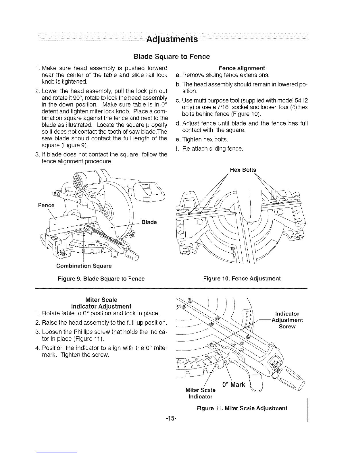
Blade Square to Fence
1. Make sure head assembly is pushed forward
near the center of the table and slide rail lock a.
knob istightened, b.
2. Lower the head assembly, pull the lock pin out
and rotate it90°, rotateto lock the head assembly c.
in the down position. Make sure table is in 0°
detent and tighten miter lock knob. Place a com-
bination square against the fence and next to the
blade as illustrated. Locate the square properly d.
so it does notcontact thetooth of saw blade.The
saw blade should contact the full length of the e.
square (Figure 9). f.
3. If blade does not contact the square, follow the
fence alignment procedure.
Fence alignment
Remove sliding fence extensions.
The head assembly should remainin loweredpo-
sition.
Use multi purpose tool (supplied with model 5412
only)or usea 7/16" socket and loosen four (4)hex
bolts behind fence (Figure 10).
Adjust fence until blade and the fence has full
contact with the square.
Tighten hex bolts.
Re-attach sliding fence.
Hex Bolts
Fence
Blade
Combination Square
Figure 9. Blade Square to Fence Figure 10. Fence Adjustment
Miter Scale
indicator Adjustment
1. Rotate table to 0° position and lock in place.
2. Raise the head assembly to the full-up position.
3. Loosen the Phillips screw that holds the indica-
tor in place (Figure 11).
4. Position the indicator to align with the 0° miter
mark. Tighten the screw.
-15-
indicator
ustment
Screw
0° Mark
Miter Scale
Indicator
Figure 11. Miter Scale Adjustment
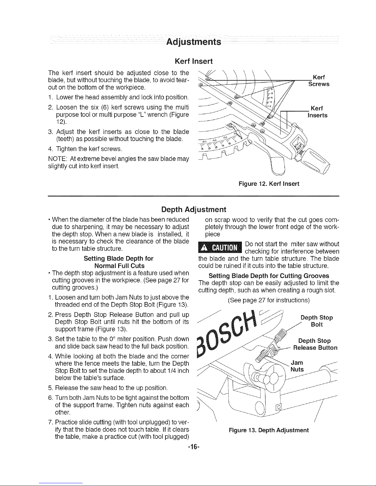
Kerr
The kerf insert should be adjusted close to the
blade, butwithout touching the blade, to avoidtear-
out on the bottom of the workpiece.
1. Lower the head assembly and lock into position.
2. Loosen the six (6) kerr screws using the multi
purpose tool ormulti purpose"L" wrench (Figure
12).
3. Adjust the kerf inserts as close to the blade
(teeth) as possible without touching the blade.
4. Tighten the kerf screws.
NOTE: Atextreme bevel angles the saw blade may
slightly cut intokerr insert.
Insert
Figure 12. Kerf Insert
Kerr
Screws
Kerf
Inserts
Depth Adjustment
• When the diameter of the blade has been reduced
due to sharpening, it may be necessary to adjust
the depth stop.When a new blade is installed, it
is necessary to check the clearance of the blade
to the turn table structure.
Setting Blade Depth for
Normal Full Cuts
• The depth stopadjustment is afeature usedwhen
cutting grooves in the workpiece. (Seepage 27 for
cutting grooves.)
1. Loosenand turn both Jam Nuts to just above the
threaded end of the Depth Stop Bolt (Figure 13).
2. Press Depth Stop Release Button and pull up
Depth Stop Bolt until nuts hit the bottom of its
support frame (Figure 13).
3. Set thetable to the 0° miter position. Push down
and slide back saw head to the full back position.
4. While looking at both the blade and the corner
where the fence meets the table, turn the Depth
Stop Boltto set the blade depth to about 1/4 inch
below the table's surface.
5. Releasethe saw head to the up position.
6. Turn bothJam Nuts to betight against the bottom
of the support frame. Tighten nuts against each
other.
on scrap wood to verify that the cut goes com-
pletely through the lower front edge of the work-
piece
Do not start the miter saw without
checking for interference between
the blade and the turn table structure. The blade
could be ruined if it cuts into the table structure.
Setting Blade Depth for Cutting Grooves
The depth stop can beeasily adjusted to limit the
cutting depth, such as when creating a rough slot.
(See page 27 for instructions)
Depth Stop
Bolt
Depth Step
Release Button
7. Practice slide cutting (withtool unplugged) to ver-
ify that the blade does not touch table. Ifit clears
the table, make a practice cut (with tool plugged)
Figure 13. Depth Adjustment
-16-
Transportingl Placement and lVlounting
Toavoid injury always observe the
following:
• Unplug electric cord. Before transporting the saw,
rotate head and lock assembly to 60° right miter,
lock into detent, slide head assembly to the middle
of it's rail, tighten the slide rail lock knob and lock
the head assembly in the lowered position.
Lifting Saw
•To avoid back injury, hold the tool close to your
bodywhen lifting. Bend your knees so you can lift
with your legs, not your back.
• Lift by using the cast-in carry handles at each
side of the bottom of the base.
•Alternate lifting method: When picking tool up
from ground, use rear carrying handle and front
carrying handle (above guard).
• Never carry the tool by the slide rails, this
may cause blade damage.
• Never lift tool by holding switch handle. This
may cause serious damage,
• Never carrythe miter saw bythe power cordor the
operational handle. Attempting to lift or carry the
tool by the power cord will damage the insulation
andthe wire connections resulting in electric shock
or fire.
• Observe the position of the saw. People standing
behind it could be injured by thrown debris.
• Place the saw ona firm, level surface where there
is plenty of room forhandling andproperly support-
ing the workpiece.
• Bolt, nailor clamp the saw to its support.
Be careful not to over-drive nail
or over-torque the bolt, This
could crack foot or damage base.
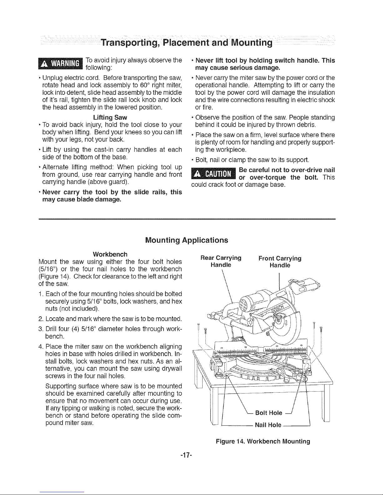
Mounting Applications
Workbench
Mount the saw using either the four bolt holes
(5/16") or the four nail holes to the workbench
(Figure14). Check for clearance to the leftand right
of the saw.
1. Each of the four mounting holes should be bolted
securely using5/16" bolts, lock washers, and hex
nuts (not included).
2. Locateand mark where the saw isto be mounted.
3. Drill four (4) 5/16" diameter holes through work-
bench.
4. Place the miter saw on the workbench aligning
holes in base with holes drilled in workbench. In-
stall bolts, lock washers and hex nuts. As an al-
ternative, you can mount the saw using drywall
screws in the four nail holes.
Supporting surface where saw is to be mounted
should be examined carefully after mounting to
ensure that no movement can occur during use.
Ifanytipping or walking is noted, secure the work-
bench or stand before operating the slide com-
pound miter saw.
Rear Carrying Front Carrying
Handle Handle
Nail Hole-
Figure 14. Workbench Mounting
-17-
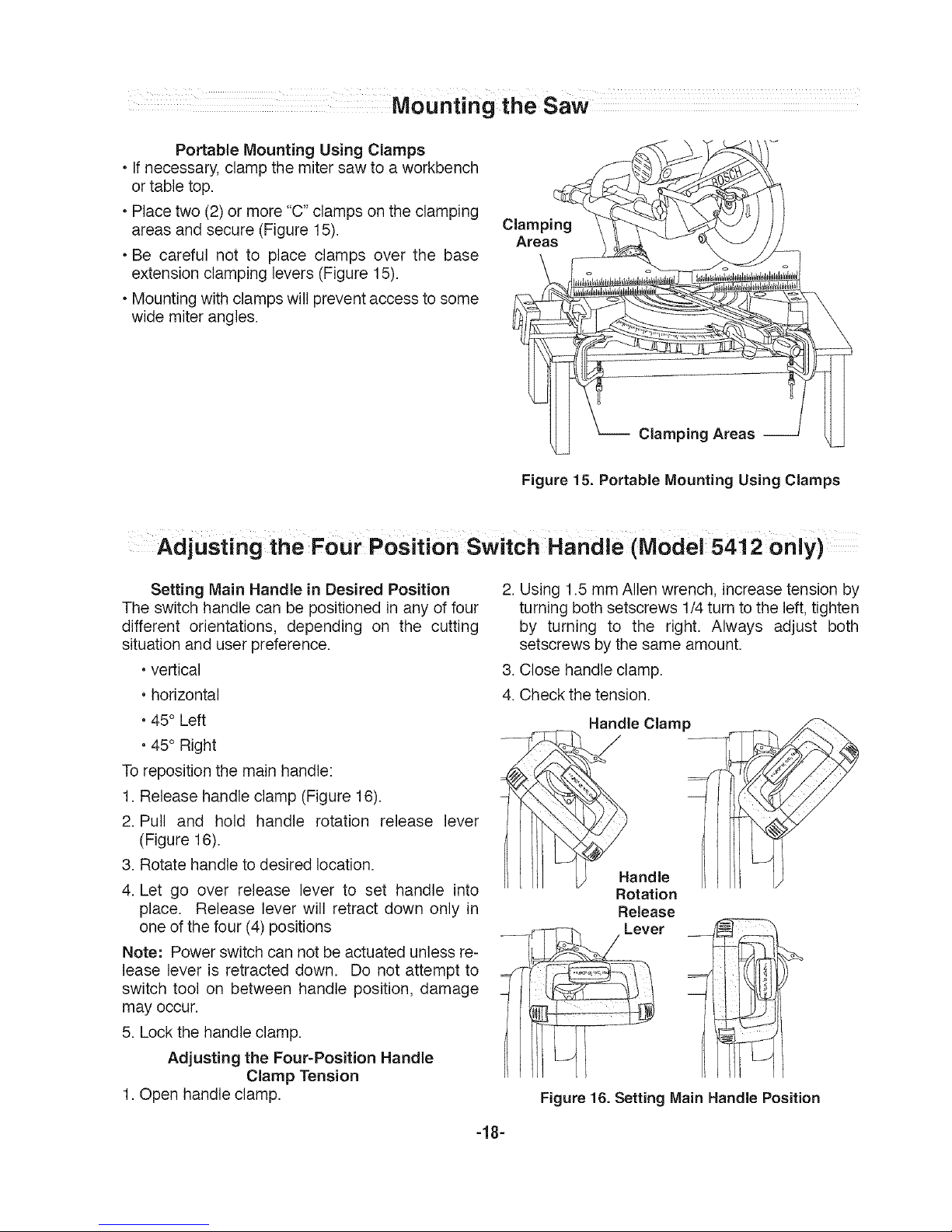
Portable Mounting Using Clamps
• Ifnecessary, clamp the miter saw to a workbench
or table top.
• Placetwo (2) or more"C" clamps on the clamping
areas and secure (Figure 15).
• Be careful not to place clamps over the base
extension clamping levers (Figure 15).
• Mountingwith clamps will prevent access to some
wide miter angles.
Clamping
Areas
Clamping Areas
Figure 15. Portable Mounting Using Clamps
Adjusting the Four Position Switch Handle (Model 5412 only)
Setting Main Handle in Desired Position
The switch handle can be positioned in any of four
different orientations, depending on the cutting
situation and user preference.
• vertical
• horizontal
• 45° Left
• 45° Right
Toreposition the main handle:
1. Release handle clamp (Figure 16).
2. Pull and hold handle rotation release lever
(Figure 16).
3. Rotate handle to desired location.
4. Let go over release lever to set handle into
place. Release lever will retract down only in
one of the four (4) positions
Note: Power switch can not be actuated unless re-
lease lever is retracted down. Do not attempt to
switch tool on between handle position, damage
may occur.
5. Lock the handleclamp.
Adjusting the Four-Position Handle
Clamp Tension
1. Open handle clamp.
2. Using 1.5 mm Alien wrench, increase tension by
turning both setscrews 1/4 turn to the left, tighten
by turning to the right. Always adjust both
setscrews bythe same amount.
3. Close handle clamp.
4. Check the tension.
Handle Clamp /_
Rotation
Release
Lever
Figure 16. Setting Main Handle Position
-18-
BasicSaw Operations
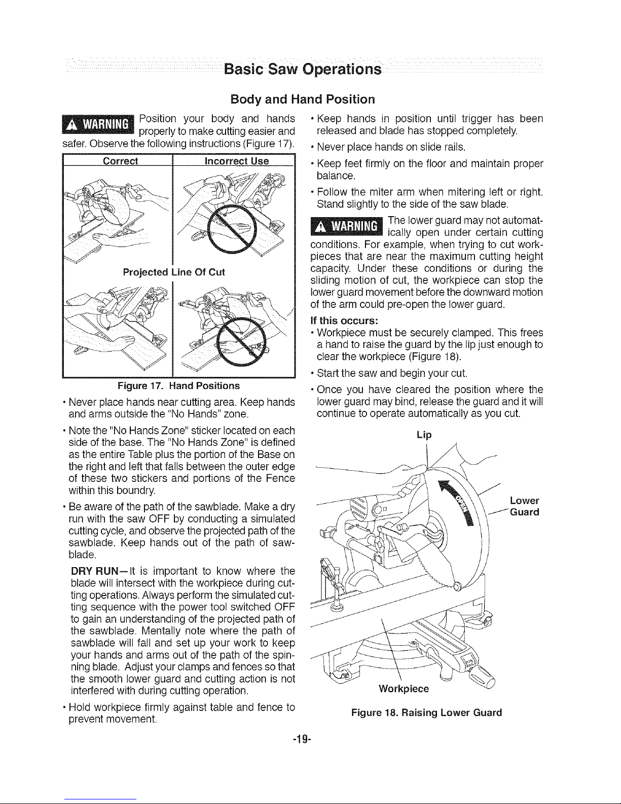
Body and Hand Position
_ osition your body and hands
properlyto make cutting easier and
safer. Observe the followinginstructions (Figure 17).
Correct
Incorreqt ,Use......
Projected Line Of Cut
Figure 17. HandPositions
• Never place hands nearcutting area. Keep hands
and arms outside the "No Hands" zone.
• Keep hands in position until trigger has been
released and blade has stopped completely.
• Never place hands on slide rails.
• Keep feet firmly on the floor and maintain proper
balance.
• Follow the miter arm when mitering left or right.
Stand slightly to the side of the saw blade.
The lowerguard may notautomat-
ically open under certain cutting
conditions. For example, when trying to cut work-
pieces that are near the maximum cutting height
capacity. Under these conditions or during the
sliding motion of cut, the workpiece can stop the
lower guard movement before the downward motion
of the arm could pre-open the lower guard.
If this occurs:
• Workpiece must be securely clamped. This frees
a hand to raisethe guard by the lipjust enough to
clear the workpiece (Figure t8).
• Start the saw and begin your cut.
• Once you have cleared the position where the
lower guard may bind, release the guard and it will
continue to operate automatically as you cut.
• Notethe "No Hands Zone" stickerlocated on each
side of the base. The "No Hands Zone" isdefined
as the entire Table plus the portion ofthe Base on
the right and left that fails between the outer edge
of these two stickers and portions of the Fence
within this boundry.
• Be aware of the path of the sawblade. Makea dry
run with the saw OFF by conducting a simulated
cutting cycle, and observethe projected path ofthe
sawblade. Keep hands out of the path of saw-
blade.
DRY RUN--It is important to know where the
blade will intersect with the workpiece during cut-
ting operations. Always perform the simulated cut-
ting sequence with the power tool switched OFF
to gain an understanding of the projected path of
the sawblade. Mentally note where the path of
sawblade will fall and set up your work to keep
your hands and arms out of the path of the spin-
ning blade. Adjustyour clamps andfences so that
the smooth lower guard and cutting action is not
interfered with during cutting operation.
• Hold workpiece firmly against table and fence to
prevent movement.
Figure 18. Raising Lower Guard
-lg-
BasicSawOperations
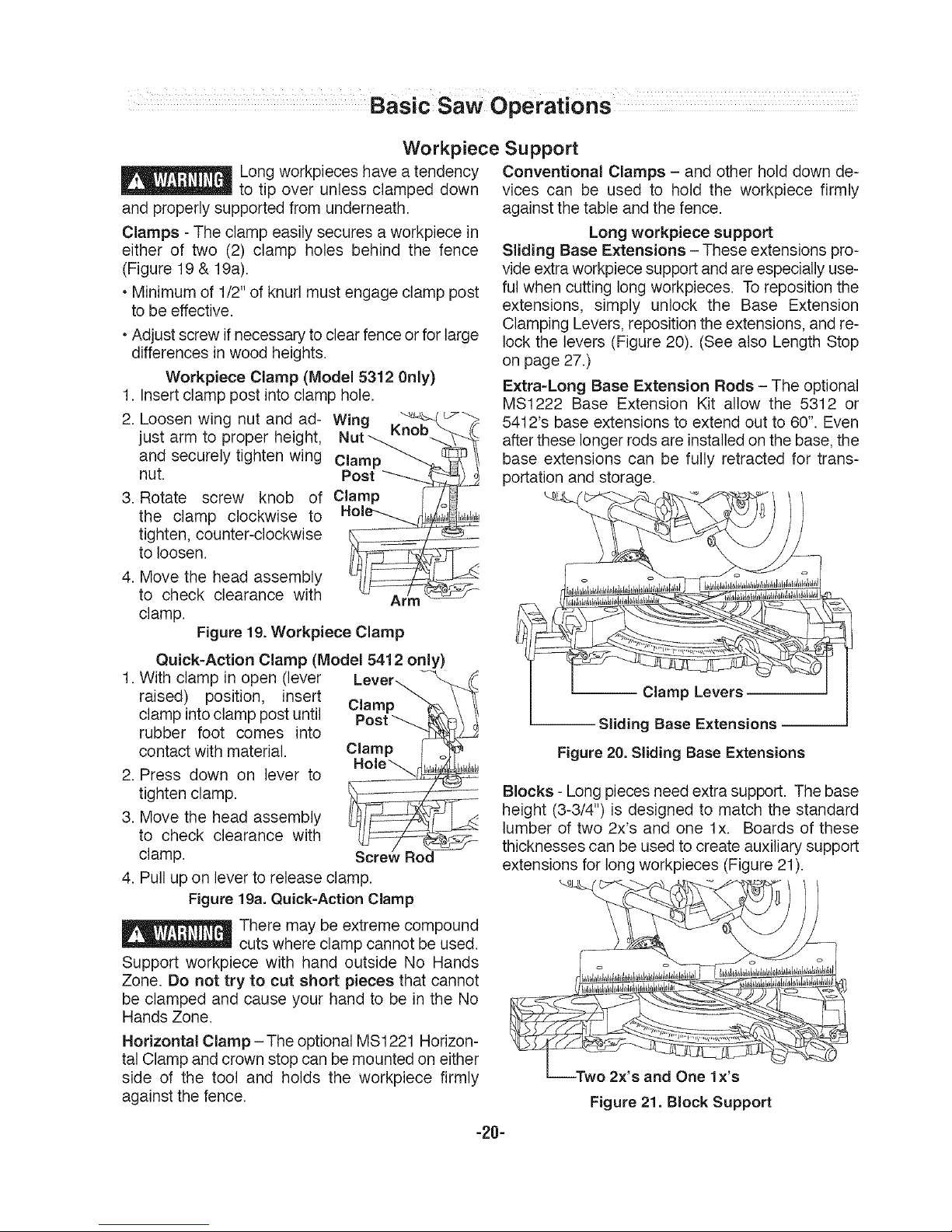
Workpiece Support
Long workpieces have atendency
_to tip over unless clamped down
and properly supported from underneath.
Clamps - The clamp easily secures a workpiece in
either of two (2) clamp holes behind the fence
(Figure 19 & 19a).
• Minimum of 1/2" of knurl must engage clamp post
to be effective.
• Adjust screw if necessary to clear fence or for large
differences in wood heights.
Workpiece Clamp (Model 5312 0nly)
1. Insertclamp post intoclamp hole.
2. Loosen wing nut and ad- Wing
just arm to proper height,
and securely tighten wing
nut.
3. Rotate screw knob of
the clamp clockwise to
tighten, counter-clockwise
to loosen.
4. Move the head assembly
to check clearance with Ar
clamp.
Figure19.Workpiece Clamp
Quick-Action Clamp (Model 5412 only)
1. With clamp in open (lever
raised) position, insert Clamp
clamp into clamp post until Post
rubber foot comes into
contact with material. Clamp
2. Press down on lever to
tighten clamp.
3. Move the head assembly
to check clearance with
clamp.
4. Pullup on lever to release clamp.
Figure19a. Quick-ActionClamp
_ There may be extreme compound
cuts where clamp cannot be used.
Support workpiece with hand outside No Hands
Zone. Do not try to cut short pieces that cannot
be clamped and cause your hand to be in the No
Hands Zone.
Horizontal Clamp - The optional MS1221 Horizon-
tal Clamp and crown stop can be mounted on either
side of the tool and holds the workpiece firmly
against thefence.
Conventional Clamps - and other hold down de-
vices can be used to hold the workpiece firmly
against the table and the fence.
Long workpiece support
Sliding Base Extensions - These extensions pro-
vide extra workpiece support and are especially use-
fulwhen cutting long workpieces. To reposition the
extensions, simply unlock the Base Extension
Clamping Levers, reposition the extensions, and re-
lock the levers (Figure 20). (See also Length Stop
on page 27.)
Extra-Long Base Extension Rods - The optional
MS1222 Base Extension Kit allow the 5312 or
5412's base extensions to extend outto 60". Even
afterthese longer rods are installedon the base,the
base extensions can be fully retracted for trans-
portation and storage.
Figure 20.Sliding Base Extensions
Blocks - Long pieces need extra support. The base
height (3-3/4") is designed to match the standard
lumber of two 2x's and one lx. Boards of these
thicknesses can be used to create auxiliary support
extensions for long workpieces (Figure 21).
Figure 21.Block Support
-20-
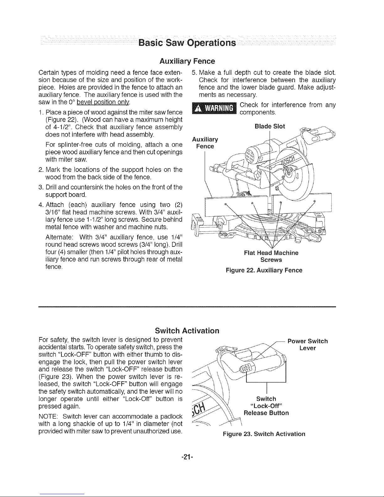
Auxiliary Fence
Certain types of molding need a fence face exten-
sion because of the size and position of the work-
piece. Holes are provided in the fence to attach an
auxiliary fence. The auxiliary fence is usedwith the
saw in the 0° bevel position only..
1. Place a piece of wood againstthe mitersaw fence
(Figure 22). (Wood can have a maximum height
of 4-1/2". Check that auxiliary fence assembly
does not interfere with head assembly.
For splinter-free cuts of molding, attach a one
piece wood auxiliary fence and then cutopenings
with miter saw.
2. Mark the locations of the support holes on the
wood from the back side of the fence.
3. Drill and countersink the holes on the front of the
support board.
4. Attach (each) auxiliary fence using two (2)
3/16" flat head machine screws. With 3/4" auxil-
iary fence use 1-1/2" long screws. Secure behind
metal fence with washer and machine nuts.
Alternate: With 3/4" auxiliary fence, use 1/4"
round head screws wood screws (3/4" long). Drill
four (4)smaller (then1/4" pilot holes through aux-
iliary fence and run screws through rearof metal
fence.
5. Make a full depth cut to create the blade slot.
Check for interference between the auxiliary
fence and the lower blade guard. Make adjust-
ments as necessary.
_ Check for interference from any
components.
Auxiliary
Fence
Blade Slot
Flat Head Machine
Screws
Figure 22. Auxiliary Fence
Switch Activation
For safety, the switch lever is designed to prevent
accidental starts.To operate safety switch, press the
switch "Lock-OFF" button with either thumb to dis-
engage the lock, then pull the power switch lever
and release the switch "Lock-OFF" release button
(Figure 23). When the power switch lever is re-
leased, the switch "Lock-OFF" button will engage
the safety switch automatically, and the leverwill no
longer operate until either "Lock-Off" button is
pressed again.
NOTE: Switch lever can accommodate a padlock
with a long shackle of up to 1/4" in diameter (not
providedwith miter saw to preventunauthorized use.
I
Switch
"Lock-Off"
Release Button
Power Switch
Lever
Figure 23. Switch Activation
-21-
Basic Saw Operations
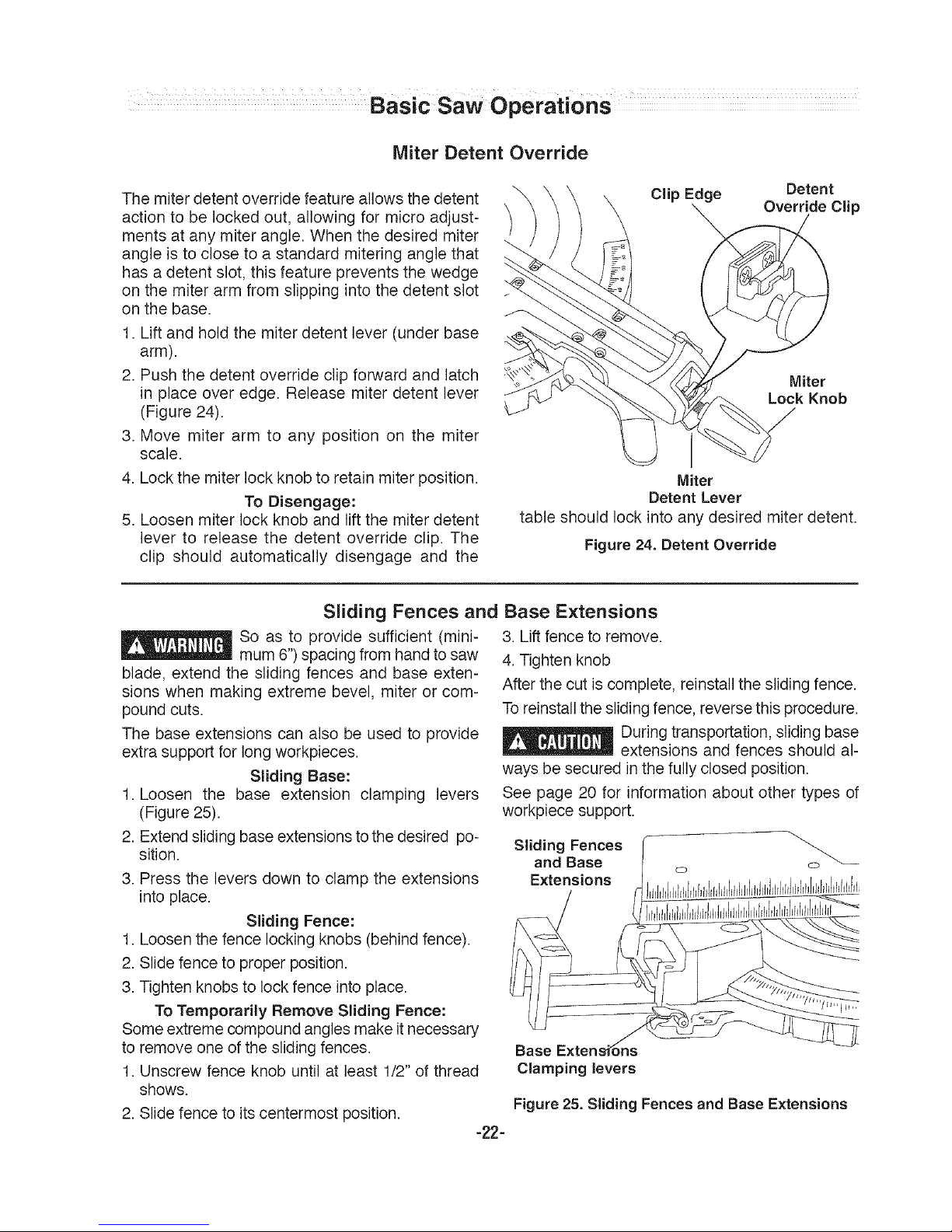
Miter Detent Override
The miter detent override feature allows the detent
action to be locked out, allowing for micro adjust-
ments at any miter angle. When the desired miter
angle is to close to a standard mitering angle that
has a detent slot, this feature prevents the wedge
on the miter arm from slipping into the detent slot
on the base.
1. Lift and hold the miter detent lever (under base
arm).
2. Push the detent override clip forward and latch
in place over edge. Release miter detent lever
(Figure 24).
3. Move miter arm to any position on the miter
scale.
4. Lock the miter lock knob to retain miter position.
To Disengage:
5. Loosen miter lock knob and lift the miter detent
lever to release the detent override clip. The
clip should automatically disengage and the
Clip Edge Detent
Override Clip
Miter
Lock Knob
Miter
Detent Lever
table should lock into any desired miter detent.
Figure 24. Detent Override
Sliding Fences and Base Extensions
So as to provide sufficient (mini- 3. Lift fence to remove.
mum 6") spacing from hand tosaw 4.Tighten knob
blade, extend the sliding fences and base exten-
sions when making extreme bevel, miter or com-
pound cuts.
The base extensions can also be used to provide
extra support for long workpieces.
Sliding Base:
1. Loosen the base extension clamping levers
(Figure 25).
2. Extendsliding base extensions to the desired po-
sition.
3. Press the levers down to clamp the extensions
into place.
Sliding Fence:
1. Loosenthe fence locking knobs (behind fence).
2. Slide fence to proper position.
3. Tighten knobsto lock fence into place.
To Temporarily Remove Sliding Fence:
Some extreme compound angles make itnecessary
to remove one of the sliding fences.
1. Unscrew fence knob until at least 1/2" of thread
shows.
2. Slide fence to its centermost position.
-22-
After the cut is complete, reinstall the sliding fence.
Toreinstall the sliding fence, reverse this procedure.
_ uring transportation, sliding base
extensions and fences should al-
ways be secured in the fully closed position.
See page 20 for information about other types of
workpiece support.
Sliding Fences o'S-
and Base
Extensions
Base
Clamping levers
Figure 25. Sliding Fences and Base Extensions
Chop Cut
•The slide rail lock knob is tightened and the head
assembly is lowered to cut through theworkpiece.
•This type of cut is used mainly for narrow pieces.
Follow these instructions for making
your chop cut:
1. Slide the head assembly to the rear as far as it
will go (Figure26).
2. Tighten the slide rail lock knob (Figure 26).
3. Properly position workpiece. Make sure work-
piece is clamped firmly against the table and the
fence.
Use clamping position that does
not interfere with operation. Before
switching on, lower head assembly to make sure
clamp clears guard and head assembly.
4. Activate the switch. Lower the head assembly
and make your cut.
5. Wait until blade comes to a complete stop before
returning head assembly to the raised position
and/or removing workpiece.
Slide Rail
Figure 26. Chop Cut
Slide Cut
• The slide rail lock knob is loose, the head assem-
bly is pulled towards the operator, the head as-
sembly is lowered to the workpiece and then
pushed to the rear of the saw to make the cut.
• This type of cut is used mainly for wide pieces.
• A positive blade hook of 10 degrees or more is
recommended for best performance when mak-
ing aggressive cuts or cutting thicker materials.
_ NEVER pull the saw toward you
during a cut. The blade can sud-
denly climb up on top of the workpiece and force it-
self toward you.
Follow these instructions for
making your slide cut:
1. Properly position workpiece. Make sure work-
piece is clamped firmly against the table and the
fence.
way down and cut through the edge of the work-
piece.
5. Push (but do not force) the head assembly to-
wards the fence to the full rear position to com-
plete the cut.
6. Wait until blade comes to a complete stop before
returning head assembly to the raised position
and/or removing workpiece.
2
Use clamping position that does
not interfere with operation. Before
switching on, lower head assembly to make sure
clamp clears guard and head assembly.
2. Loosenthe slide rail lock knob.
3. Grasp the switch handle and pull the head as-
sembly away from the fence, until the bladeclears
the workpiece or to its maximum extension if
blade cannot clear the workpiece (Figure 27).
4. Activate the switch. Lower the assembly all the
-23-
Figure 27. SJJdeCut
Miter Cut
• A"mitercut" isa cross-cutmadewiththe bladevertical
(non-tilted)ata horizontalangle relativeto the fence.
• A miter cut is made at O° bevel and any miter angle
in the range from 52° left to 60° right.
• The miter scale shows the angle of the blade
relative tothe fence angle iscast-in on the table for
easy reading.
• Positive detents have been provided for fast and
accurate mitering at 0°, 15°, 22.5 °, 31.6°
and 45° left and right and 60° right.
• The crown molding detents (left and right) are at
31.6° (See Cutting Crown Molding for more infor-
mation page 29).
• For precision settings at angles next to the
detents, use the detent override to lock out the
detent. This prevents the wedge on the detent
lever from slipping back intothe detent.
• A miter cut can be made as either a chop cut or a
slide cut, depending on the width ofthe workpiece.
• The kerfinserts should beas close to the blade as
possible without touching the blade (see Kerf In-
serts for adjustment procedures).
Follow these instructions for making
your miter cut:
1. Loosen miter lock knob. Lift miter detent lever
and move the saw to the desired angle, using ei-
ther the detents or the miter scale. Tighten miter
lock knob (Figure 26).
2. Extendthe base extensions and fenceon the side
on whichthe cut will be made. (SeeSliding Fence
and Base Extension on page 22).
3. Properly position workpiece. Make sure work-
piece is clamped firmly against the table or the
fence.
Use clamping position that does
not interfere with operation. Before
switching on, lower head assembly to make sure
clamp clears guard and head assembly.
4. Follow procedures for either chop cut or slide cut
(see page 23).
5.Wait until blade comes to acomplete stop before
returning head assembly to the raised position
and/or removing workpiece.
Quick
Action-
Climp
Workpiece
Miter
Scale Detents
Figure 28. Miter Cut
Miter Lock
Knob
Bevel Cut
• A "bevel cut" is a cross-cut made with the blade
perpendicular to the fence buttilted away from the
vertical position.
• A bevel cut is made at0° miter andany bevel angle
in the range of -47°to 47°.
• The bevel scale is sized and positioned for easy
reading.
• The front-positioned bevel range selector knob
provides three bevel range choices.
• There are factory set bevel stops at 0° and 45° on
both the left and right. (See Adjustment section if
adjustments are required.)
• There are also positive crown molding bevel
stops at 33.9 ° on both the left and right.
-24-
Disengage this stop unless using the 33.9°
angle (See Cutting Crown Molding for details.)
• A bevel cut can be made as either achop cut or a
slide cut depending on the width of the workpiece.
• The front-positioned bevel lock lever locks the
head assembly at the desired bevel angle.
1. Liftthe bevel lock lever to unlock. Choose the de-
sired bevel range using the bevel range selector
knob. If in the 0° position and moving to the 0°-to-
45° rightrange or 47°-to-47° range, it may be nec-
essary to move the head assembly slightly to the
left before the bevel range selector knob can be
turned. Applying pressure tothe cuttingassembly
may not allow you to move the bevel range se-
lector Knob.
BevelRange1=45°Leftto0°
Thisleftsidebevelrangeisthedefaultsetting
Tooperateinrange1:
1.MovetheleftslidingfencetoclearA_°
saw assembly and re-lock (Figure 29). _
2.Li.bevellocklevertothetableheightLeft
with the left hand (Figure 30).
3. Grasp the front carry handle with the right hand
and tilt saw head to angle desired.
4. Once in the desired bevel position, fully press
down bevel lock lever below table height
(Figure 29)..
Without turning the saw on, practice the cutting ac-
tion to make sure the fence clears the guards and
adjust as necessary.
Bevel Range 2 = 0° to 45° Right o
To operate in range 2: 0"45
1. Move right sliding fence to clear_::_itlh, _
saw assembly and re-lock (Figure _ "' _::_' "_"
29).
2. Liftbevel lock lever to the table height with the left
hand (Figure30).
3. Graspthe front carry handle with the lefthand and
tilt saw head slightly to the left while rotating the
spring-loaded bevel range selector knobwith the
right hand so the symbol " 45-0° " lines up with
the arrow on the table (Figure 31). The saw as-
sembly may now be tilted to a right bevel angle
up to the 45° stop.
4. Once in the desired bevel position press down
bevel lock lever below table height.
NOTE: When the saw assembly is tilted back left
past 0°, the bevelcontrol knob will snap back to the
default bevel range 1.This isdesigned to regainthe
pre-set bevel stop at the important 0° position.
Bevel Range 3 = 47° Left to 47° Right
This full capacity bevel range setting overrides all
preset stops and allows for cutting at bevel angles
beyond the normal 45° on either side.
To operate in range 3: 47047°
1. Move left and right-sliding fences
to clear saw assembly and re-lock MaX
(Figure 29).
2. Lift bevel lock lever to the table heightwiththe left
hand(Figure 30).
3. Graspthe front carry handle with the lefthand and
tilt saw head slightly to the left while rotating the
spring-loaded bevel range selector knobwith the
right hand so the symbol "47-47 °" lines up with
the arrow on the table (Figure 31). The saw as-
-25-
sembly may now be tilted to any angle from 47°
left to 47°right.
4. Once in the desired bevel position, fully press
down bevel lock lever below table height.
Follow these instructions for
making your bevel cut:
5. Extend the base extensions and fence on the side
on whichthe cut will be made. (See Sliding Fence
and Base Extension on page 22).
6. Properly position workpiece. Make sure work
piece is clamped firmly against the table and the
fence.
Use clamping position that does not interfere with
operation. Before switching on, lower head assem-
bly to make sure clamp clears guard and head as-
sembly.
7. Follow the procedures for either a chop cut or
slide cut (see page 23).
8. Wait until blade comes to a complete stop before
returning head assembly to the raised position
and/or removing workpiece.
Front Carry Handle
Sliding Fence
Figure 29.
Lock Lever
Figure 30.
Figure 31.
Bevel
__Range
Sele_or
Knob
Compound Cuts
• A "compound cut" is a cross-cut made with the
blade both at a horizontal angle relative to the
fence (at a miter angle) and tilted away from the
vertical position (ata bevel angle).
• A compound cut can be made as either a chop
cut or a slide cut depending on the width of the
workpiece.
• Because it may take several tries to obtain the
desired compound angle, perform test cuts on
scrap material before making your cut.
Follow these instructions for
making your compound cut:
1. Extend the base extensions and fences on the
side on which the cut will be made. (See Sliding
Fences and Base Extensions on page 22.)
2. Properly position workpiece. Make sure work-
piece is clamped firmly against the table or the
fence.
Use clamping position that does
not interfere with operation. Be-
fore switching on, lower head assembly to make
sure clamp clears guard and head assembly.
3. Set miter and bevel angles according to the in-
structions on page 24 and 25 for miter and
bevel cuts.
4. Follow the procedures for either chop cut or
slide cut (see page 23).
5. Wait until blade comes to a complete stop be-
fore returning head assembly to the raised po-
sition and / or removing workpiece.
Quick-Action
Clamp
Workpiece
Sliding Bevel Angle Miter
Base Scale Angle
Figure 32. Compound Cut
-26-
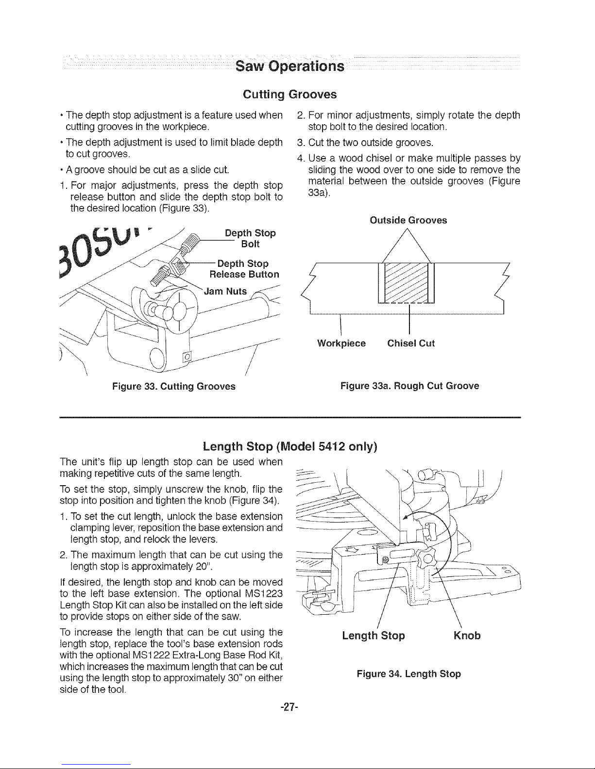
Cutting Grooves
•The depth stop adjustment is afeature usedwhen
cutting grooves in the workpiece.
•The depth adjustment is used to limit blade depth
to cut grooves.
•A groove should be cut as a slide cut.
1. For major adjustments, press the depth stop
release button and slide the depth stop bolt to
the desired location (Figure 33).
Depth Stop
Bolt
Stop
Release Button
2. For minor adjustments, simply rotate the depth
stop bolt to the desired location.
3. Cut the two outside grooves.
4. Use a wood chisel or make multiple passes by
sliding the wood over to one side to remove the
material between the outside grooves (Figure
33a).
Workpiece
Outside Grooves
Chisel Cut
Figure 33. Cutting Grooves
Figure 33a. Rough Cut Groove
Length Stop (Model 5412 only)
The unit's flip up length stop can be used when
making repetitive cuts of the same length.
To set the stop, simply unscrew the knob, flip the _-
stop into position and tighten the knob (Figure 34).
1.To set the cut length, unlock the base extension
clamping lever, reposition the base extension and
length stop, and relock the levers.
2. The maximum length that can be cut using the
length stop is approximately 20". _/_
Ifdesired, the length stop and knob can be moved
to the left base extension. The optional MS1223
Length Stop Kit can also be installed on the leftside
to provide stops on either side of the saw.
To increase the length that can be cut using the
length stop, replace the tool's base extension rods
with the optional MS1222 Extra-Long Base Rod Kit,
which increasesthe maximum lengththat can be cut
using the length stop to approximately 30" on either
side ofthe tool.
Length Stop Knob
Figure 34. Length Stop
-27-
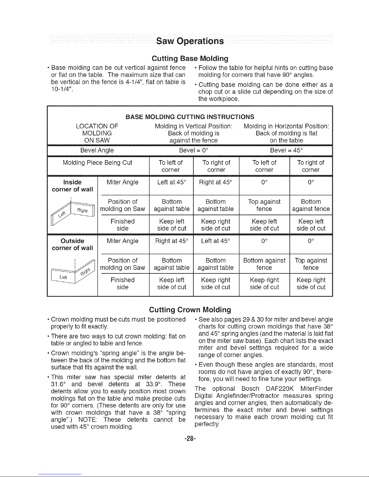
CuttingBaseMolding
•Basemoldingcanbecutverticalagainstfence •Followthetableforhelpfulhintsoncuttingbase
orfiatonthetable.Themaximumsizethatcan moldingforcornersthathave90°angles.
beverticalonthefenceis4-1/4",fiatontableis •Cuttingbasemoldingcanbedoneeitherasa
10-1/4". chopcutoraslidecutdependingonthesizeof
theworkpiece.
LOCATIONOF
MOLDING
ONSAW
BevelAngle
BASE MOLDING CUTTING iNSTRUCTiONS
Molding in Vertical Position: Molding in Horizontal Position:
Back of molding is Back of molding is flat
against the fence on the table
Bevel = 0° Bevel = 45°
Molding Piece Being Cut
To left of
corner
Toright of
corner
Toleft of
corner
Toright of
corner
inside
corner of wall
Outside
corner of wall
Miter Angle
Position of
molding on Saw
Finished
side
Miter Angle
Left at 45 °
Bottom
against table
Keep left
side of cut
Right at 45 °
Right at 45°
Bottom
against table
Keep right
side of cut
Left at 45°
0 o
Top against
fence
Keep left
side of cut
0o
0 o
Bottom
against fence
Keep left
side of cut
0 o
Position of Bottom Bottom Bottom against Top against
molding on Saw against table against table fence fence
Finished Keep left Keep right Keep right Keep right
side side of cut side of cut side of cut side of cut
Cutting Crown Molding
• Crown molding must be cuts must be positioned
properly to fit exactly.
• There are two ways to cut crown molding: fiat on
table or angled to table andfence.
• Crown molding's "spring angle" is the angle be-
tween the back of the molding and the bottom fiat
surface that fits against the wall.
• This miter saw has special miter detents at
31.6° and bevel detents at 33.9°. These
detents allow you to easily position most crown
moldings fiat on the table and make precise cuts
for 90° corners. (These detents are only for use
with crown moldings that have a 38° "spring
angle".) NOTE: These detents cannot be
used with 45° crown molding.
• See also pages 29& 30 for miter and bevel angle
charts for cutting crown moldings that have 38°
and 45° spring angles (and the material is laid fiat
on the miter saw base). Each chart lists the exact
miter and bevel settings required for a wide
range of corner angles.
• Even though these angles are standards, most
rooms do not have angles of exactly 90°, there-
fore, you will need to fine tune your settings.
The optional Bosch DAF220K MiterFinder
Digital Anglefinder/Protractor measures spring
angles and corner angles, then automatically de-
termines the exact miter and bevel settings
necessary to make each crown molding cut fit
perfectly.
-28-
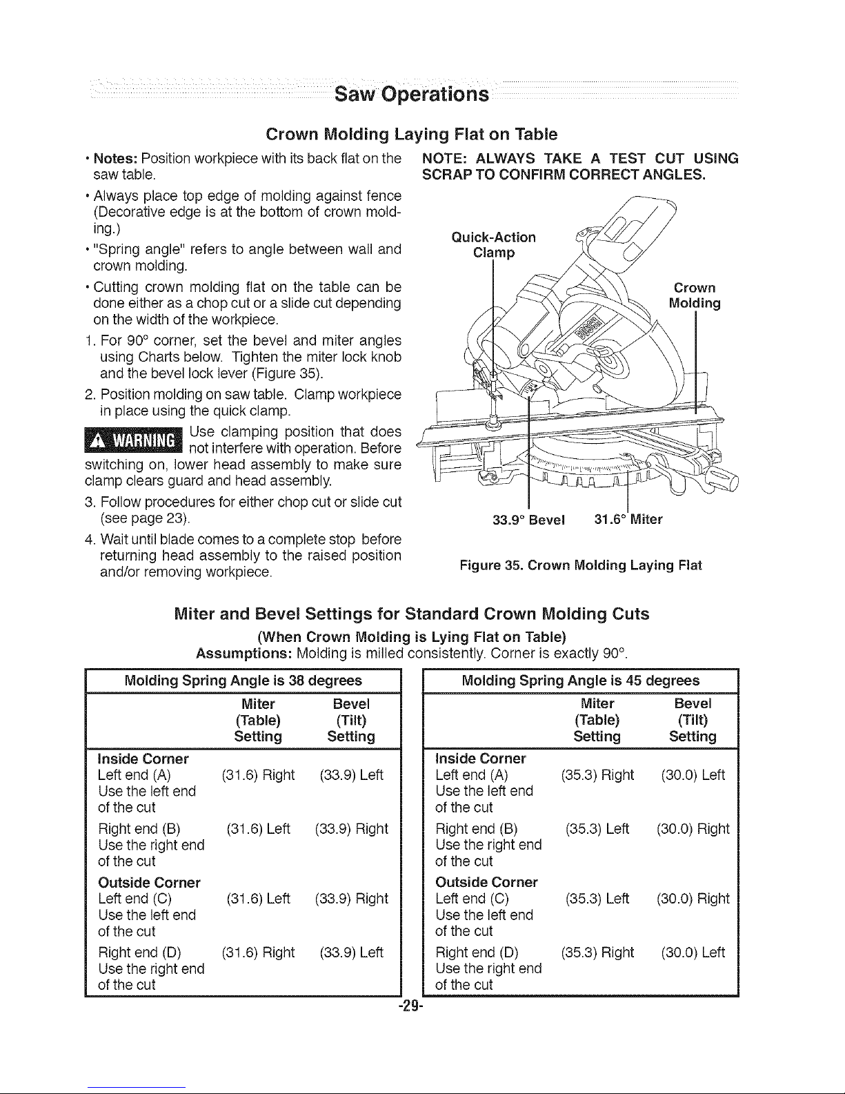
Crown Molding Laying Flat on Table
• Notes: Positionworkpiece with itsback fiat on the NOTE: ALWAYS TAKE A TEST CUT USING
saw table. SCRAP TO CONFIRM CORRECT ANGLES.
•Always place top edge of molding against fence
(Decorative edge is at the bottom of crown mold-
ing.)
•"Spring angle" refers to angle between wall and
crown molding.
• Cutting crown molding fiat on the table can be
done eitheras a chop cut or a slide cut depending
on the width of the workpiece.
1. For 90° corner, set the bevel and miter angles
using Charts below. Tighten the miter lock knob
and the bevel lock lever (Figure 35).
2. Position molding on saw table. Clamp workpiece
in place using thequick clamp.
Use clamping position that does
not interfere with operation. Before
switching on, lower head assembly to make sure
clamp clears guard and head assembly.
3. Follow procedures for either chop cut or slide cut
(see page 23).
4. Wait untilblade comes to a complete stop before
returning head assembly to the raised position
and/or removing workpiece.
Quick-Action
Clamp
Crown
Molding
33.9 ° Bevel 31.6 ° Miter
Figure 35. Crown Molding Laying Flat
Miter and Bevel Settings for Standard Crown Molding Cuts
(When Crown Molding is Lying Flat on Table)
Assumptions: Molding is milled consistently. Corner is exactly 90°.
Molding Spring Angle is 38 degrees
Miter Bevel
(Table) (Tilt)
Setting Setting
Inside Corner
Left end (A) (31.6) Right (33.9) Left
Use the left end
of the cut
Right end (B) (31.6) Left (33.9) Right
Use the right end
of the cut
Outside Corner
Left end (C) (31.6) Left (33.9) Right
Use the left end
of the cut
Right end (D) (31.6) Right (33.9) Left
Use the right end
of the cut
Molding Spring Angle is 45 degrees
Miter Bevel
(Table) (Tilt)
Setting Setting
Inside Corner
Leftend (A) (35.3) Right (30.0) Left
Use the left end
of the cut
Right end (B) (35.3) Left (30.0) Right
Use the right end
of the cut
Outside Corner
Leftend (C) (35.3) Left (30.0) Right
Use the left end
of the cut
Right end (D) (35.3) Right (30.0) Left
Use the right end
of the cut
-2g-
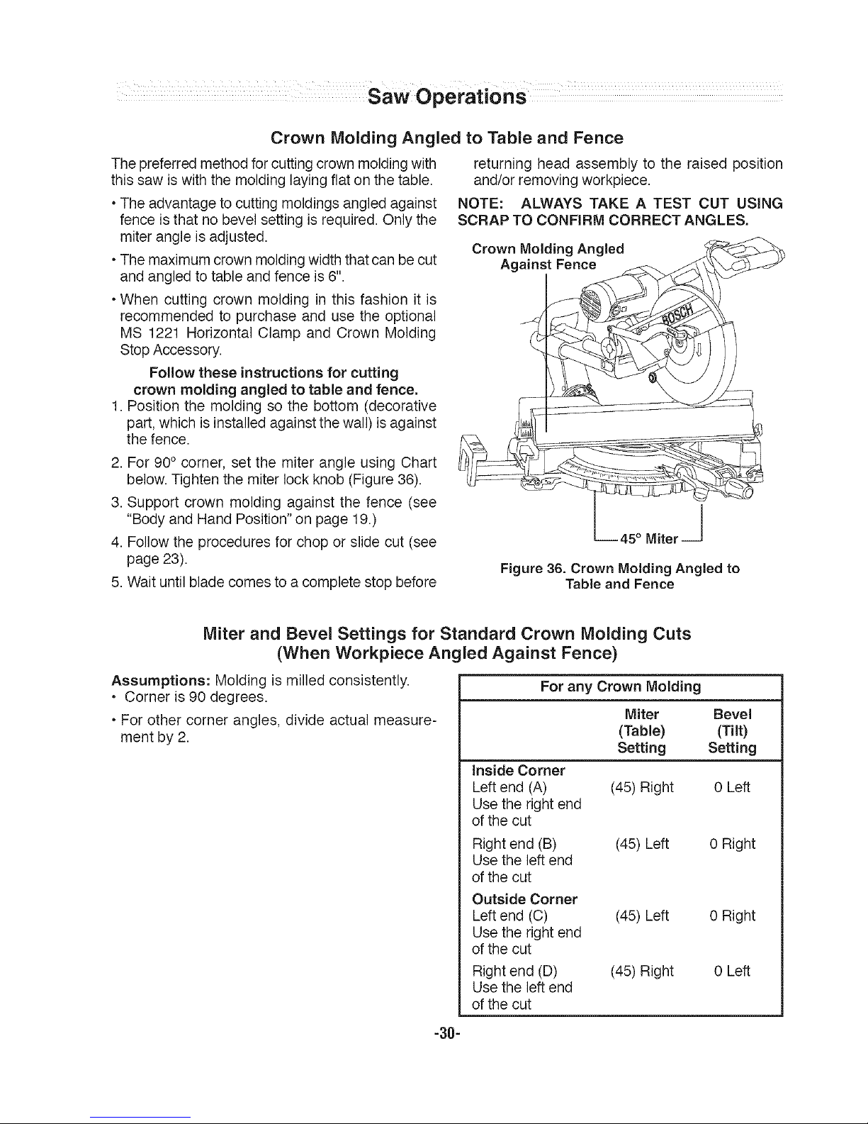
CrownMoldingAngled to Table and Fence
The preferred method for cutting crown molding with
this saw is with the molding laying fiat on the table.
• The advantage to cutting moldings angled against
fence isthat no bevel setting is required. Only the
miter angle is adjusted.
• The maximum crown molding width that can becut
and angled to table and fence is 6".
• When cutting crown molding in this fashion it is
recommended to purchase and use the optional
MS 1221 Horizontal Clamp and Crown Molding
Stop Accessory.
Follow these instructions for cutting
crown molding angled to table and fence,
1. Position the molding so the bottom (decorative
part, which isinstalled against the wall)is against
the fence.
2. For90° corner, set the miter angle using Chart
below. Tighten the miter lock knob (Figure 36).
3. Support crown molding against the fence (see
"Body and Hand Position" on page 19.)
4. Followthe procedures for chop or slide cut (see
page 23).
5. Wait until blade comes to a complete stop before
returning head assembly to the raised position
and/or removing workpiece.
NOTE: ALWAYS TAKE A TEST CUT USING
SCRAP TO CONFIRM CORRECT ANGLES,
Crown Molding Angled __
L--- 45 ° Miter --J
Figure 36. Crown Molding Angled to
Table and Fence
Miter and Bevel Settings for Standard Crown Molding Cuts
(When Workpiece Angled Against Fence)
Assumptions: Molding is milled consistently.
• Corner is 90 degrees.
• For other corner angles, divide actual measure-
ment by 2.
For any Crown Molding
Miter Bevel
(Table) (Tilt)
Setting Setting
inside Corner
Leftend (A) (45) Right 0 Left
Use the right end
of the cut
Right end (B) (45)Left 0 Right
Use the left end
of the cut
Outside Corner
Leftend (C) (45)Left 0 Right
Use the right end
of the cut
Right end (D) (45) Right 0 Left
Use the left end
of the cut
-30-
 Loading...