

Bosch 53518 User Manual [en, es, fr]
IMPORTANT: IMPORTANT : IMPORTANTE:
Read Before Using Lire avant usage Leer antes de usar
Operating/Safety Instructions
Consignes de fonctionnement/sécurité
Instrucciones de funcionamiento y seguridad
53514
53518
For English Parlez-vous français? ¿Habla español?
See page 2 Voir page 16 Ver página 30
1-877-BOSCH99 (1-877-267-2499) www.boschtools.com
Call Toll Free
for Consumer Information
& Service Locations
Pour renseignement des
consommateurs et centres
de service, appelez au
numéro gratuit :
Llame gratis para
obtener información
para el consumidor y
ubicaciones de servicio
BM 2610925944 6-05 6/10/05 11:50 AM Page 1

-2-
Work area safety
Keep work area clean and well lit.
Cluttered or dark areas invite accidents.
Do not operate power tools in explosive
atmospheres, such as in the presence of
flammable liquids, gases or dust. Power
tools create sparks which may ignite the dust
or fumes.
Keep children and bystanders away while
operating a power tool. Distractions can
cause you to lose control.
Electrical safety
Power tool plugs must match the outlet.
Never modify the plug in any way. Do not
use any adapter plugs with earthed
(grounded) power tools. Unmodified plugs
and matching outlets will reduce risk of
electric shock.
Avoid body contact with earthed or
grounded surfaces such as pipes,
radiators, ranges and refrigerators. There
is an increased risk of electric shock if your
body is earthed or grounded.
Do not expose power tools to rain or wet
conditions. Water entering a power tool will
increase the risk of electric shock.
Do not abuse the cord. Never use the cord
for carrying, pulling or unplugging the
power tool. Keep cord away from heat, oil,
sharp edges or moving parts. Damaged or
entangled cords increase the risk of electric
shock.
When operating a power tool outdoors,
use an extension cord suitable for
outdoor use. Use of a cord suitable for
outdoor use reduces the risk of electric
shock.
Do not use AC only rated tools with a DC
power supply. While the tool may appear to
work, the electrical components of the AC
rated tool are likely to fail and create a
hazard to the operator.
If operating the power tool in damp
locations is unavoidable a Ground Fault
Circuit Interrupter (GFCI) must be used to
supply the power to your tool. GFCI and
personal protection devices like electrician’s
rubber gloves and footwear will further
enhance your personal safety.
Personal safety
Stay alert, watch what you are doing and
use common sense when operating a
power tool. Do not use a power tool while
you are tired or under the influence of
drugs, alcohol or medication. A moment of
inattention while operating power tools may
result in serious personal injury.
Use safety equipment. Always wear eye
protection. Safety equipment such as dust
mask, non-skid safety shoes, hard hat, or
hearing protection used for appropriate
conditions will reduce personal injuries.
Avoid accidental starting. Ensure the
switch is in the off-position before
plugging in. Carrying power tools with your
finger on the switch or plugging in power
tools that have the switch on invites
accidents.
Remove any adjusting key or wrench
before turning the power tool on. A wrench
or a key left attached to a rotating part of the
power tool may result in personal injury.
Do not overreach. Keep proper footing
and balance at all times. This enables
better control of the power tool in unexpected
situations.
Dress properly. Do not wear loose
clothing or jewelry. Keep your hair,
clothing and gloves away from moving
parts. Loose clothes, jewelry or long hair can
be caught in moving parts.
If devices are provided for the connection
of dust extraction and collection facilities,
ensure these are connected and properly
used. Use of these devices can reduce dust-
related hazards.
Read all instructions. Failure to follow all instructions listed below may
result in electric shock, fire and/or serious injury. The term “power tool”
in all of the warnings listed below refers to your mains-operated (corded) power tool or
battery-operated (cordless) power tool.
SAVE THESE INSTRUCTIONS
!
WARNING
General Safety Rules
BM 2610925944 6-05 6/10/05 11:50 AM Page 2

-3-
Keep handles dry, clean and free from oil
and grease. Slippery hands cannot safely
control the power tool.
Power tool use and care
Do not force the power tool. Use the
correct power tool for your application.
The correct power tool will do the job better
and safer at the rate for which it was
designed.
Do not use the power tool if the switch
does not turn it on and off. Any power tool
that cannot be controlled with the switch is
dangerous and must be repaired.
Disconnect the plug from the power
source and/or the battery pack from the
power tool before making any
adjustments, changing accessories, or
storing power tools. Such preventive safety
measures reduce the risk of starting the
power tool accidentally.
Store idle power tools out of the reach of
children and do not allow persons
unfamiliar with the power tool or these
instructions to operate the power tool.
Power tools are dangerous in the hands of
untrained users.
Maintain power tools. Check for
misalignment or binding of moving parts,
breakage of parts and any other condition
that may affect the power tools operation.
If damaged, have the power tool repaired
before use. Many accidents are caused by
poorly maintained power tools.
Keep cutting tools sharp and clean.
Properly maintained cutting tools with sharp
cutting edges are less likely to bind and are
easier to control.
Use the power tool, accessories and tool
bits etc., in accordance with these
instructions and in the manner intended
for the particular type of power tool,
taking into account the working
conditions and the work to be performed.
Use of the power tool for operations different
from those intended could result in a
hazardous situation.
Use clamps or other practical way to
secure and support the workpiece to a
stable platform. Holding the work by hand
or against your body is unstable and may
lead to loss of control.
Battery tool use and care
Recharge only with the charger specified
by the manufacturer. A charger that is
suitable for one type of battery pack may
create a risk of fire when used with another
battery pack.
Use battery tools only with specifically
designated battery packs. Use of any other
battery packs may create a risk of injury and
fire.
When battery pack is not in use, keep it
away from other metal objects like paper
clips, coins, keys, nails, screws, or other
small metal objects that can make a
connection from one terminal to another.
Shorting the battery terminals together may
cause burns or a fire.
Under abusive conditions, liquid may be
ejected from the battery, avoid contact. If
contact accidentally occurs, flush with
water. If liquid contacts eyes, additionally
seek medical help. Liquid ejected from the
battery may cause irritation or burns.
Ensure the switch is in the off position
before inserting battery pack. Inserting the
battery pack into power tools that have the
switch on invites accidents.
Service
Have your power tool serviced by a
qualified repair person using only identical
replacement parts. This will ensure that the
safety of the power tool is maintained.
Develop a periodic maintenance schedule
for your tool. When cleaning a tool be
careful not to disassemble any portion of
the tool since internal wires may be
misplaced or pinched or safety guard
return springs may be improperly
mounted. Certain cleaning agents such as
gasoline, carbon tetrachloride, ammonia, etc.
may damage plastic parts.
SAVE THESE INSTRUCTIONS
BM 2610925944 6-05 6/10/05 11:50 AM Page 3

Before using battery charger, read all
instructions and cautionary markings on
(1) battery charger, (2) battery pack, and
(3) product using battery.
Use only the charger which accompanied
your product or direct replacement as
listed in the catalog or this manual. Do not
substitute any other charger. Use only Bosch
approved chargers with your product. See
Functional Description and Specifications.
Do not disassemble charger or operate the
charger if it has received a sharp blow,
been dropped or otherwise damaged in
any way. Replace damaged cord or plugs
immediately. Incorrect reassembly or
damage may result in electric shock or fire.
Do not recharge battery in damp or wet
environment. Do not expose charger to
rain or snow. If battery case is cracked or
otherwise damaged, do not insert into
charger. Battery short or fire may result.
Charge only Bosch approved rechargeable
batteries. See Functional Description and
Specifications. Other types of batteries may
burst causing personal injury and damage.
Battery/Charger
-4-
Safety Rules for Cordless Planers
Secure the material being planed. Never
hold it in your hand or across legs. Small
workpiece must be adequately secured so
that the rotating planer blades will not pick it
up during forward motion of the planer.
Unstable support can cause the blades to
bind causing loss of control and injury.
Always start the plane before blade is in
contact with the workpiece and allow the
blade to come to full speed. Tool can
vibrate or chatter if blade speed is too slow at
beginning of cut and possibly kickback.
Check the workpiece for nails, if there are
nails, either remove or set them well
below intended finished surface. If the
planer blades strike objects like nails it may
cause the tool to kickback and serious
personal injury may result.
Disconnect battery pack from tool or
place the switch in the locked or off
position before making any assembly,
adjustments or changing accessories.
Such preventive safety measures reduce the
risk of starting the tool accidentally.
After changing blades, rotate the blade
cylinder (cutter drum) to make sure
blades are not hitting any part of the
blade head housing and the blade locking
screws are tight. Spinning blades could
strike tool housing and damage tool as well
as possible injury.
Always hold the tool firmly with both
hands for maximum control.
Never pull the plane backward over the
workpiece. Loss of control may occur.
Do not put fingers or any objects into the
chip ejector or clean out chips while tool
is running. Contact with blade drum will
cause injury.
Disconnect battery pack from tool if it
becomes necessary to remove chips. The
blades are hidden from view and you may be
cut if blade is contacted.
Never place the plane down until the
blade is completely at rest. Surface
contact with coasting blade drum may cause
the plane to walk out of control.
Some dust created by
power sanding, sawing,
grinding, drilling, and other construction
activities contains chemicals known to
cause cancer, birth defects or other
reproductive harm. Some examples of
these chemicals are:
• Lead from lead-based paints,
• Crystalline silica from bricks and cement
and other masonry products, and
• Arsenic and chromium from chemically-
treated lumber.
Your risk from these exposures varies,
depending on how often you do this type of
work. To reduce your exposure to these
chemicals: work in a well ventilated area, and
work with approved safety equipment, such
as those dust masks that are specially
designed to filter out microscopic particles.
!
WARNING
BM 2610925944 6-05 6/10/05 11:50 AM Page 4
-5-
Battery Care
When batteries are not in
tool or charger, keep them
away from metal objects. For example, to
protect terminals from shorting DO NOT
place batteries in a tool box or pocket with
nails, screws, keys, etc. Fire or injury may
result.
To prevent fire or injury
when batteries are not in
tool or charger, always place protective
cap onto end of battery pack. Protective
cap, guards against terminal shorting.
DO NOT PUT BATTERIES INTO FIRE OR
EXPOSE TO HIGH HEAT. They may
explode.
!
WARNING
!
WARNING
Charge battery pack in temperatures
above +40 degrees F (4 degrees C) and
below +105 degrees F (41 degrees C).
Store tool and battery pack in locations
where temperatures will not exceed 120
degrees F (49 degrees C). This is important
to prevent serious damage to the battery
cells.
Battery leakage may occur under extreme
usage or temperature conditions. Avoid
contact with skin and eyes. The battery
liquid is caustic and could cause chemical
burns to tissues. If liquid comes in contact
with skin, wash quickly with soap and water,
then with lemon juice or vinegar. If the liquid
contacts your eyes, flush them with water for
a minimum of 10 minutes and seek medical
attention.
Place charger on flat non-flammable
surfaces and away from flammable
materials when re-charging battery pack.
The charger and battery pack heat during
charging. Carpeting and other heat insulating
surfaces block proper air circulation which
may cause overheating of the charger and
battery pack. If smoke or melting of the case
are observed unplug the charger
immediately and do not use the battery pack
or charger.
Use of an attachment not recommended or sold by Bosch may result in a
risk of fire, electric shock or injury to
persons.
Do not attempt to disas-
semble the battery or
remove any component projecting from
the battery terminals. Fire or injury may
result. Prior to disposal, protect exposed
terminals with heavy insulating tape to
prevent shorting.
NICKEL-CADMIUM BATTERIES
If equipped with a nickel-cadmium battery, the
battery must be collected, recycled or
disposed of in an environmentally sound
manner.
“The EPA certified RBRC
Battery Recycling Seal on the
nickel-cadmium (Ni-Cd)
battery indicates Robert
Bosch Tool Corporation is
voluntarily participating in an
industry program to collect and recycle these
batteries at the end of their useful life, when
taken out of service in the United States or
Canada. The RBRC program provides a
convenient alterative to placing used Ni-Cd
batteries into the trash or the municipal waste
stream, which may be illegal in your area.
Please call 1-800-8-BATTERY for information
on Ni-Cd battery recycling and disposal
bans/restrictions in your area, or return your
batteries to a Skil/Bosch/Dremel Service
Center for recycling. Robert Bosch Tool
Corporation’s involvement in this program is
part of our commitment to preserving our
environment and conserving our natural
resources.”
NICKEL-METAL HYDRIDE BATTERIES
If equipped with a nickel-metal hydride
battery, the battery can be disposed of in a
municipal solid waste stream.
!
WARNING
Battery Disposal
BM 2610925944 6-05 6/10/05 11:50 AM Page 5
-6-
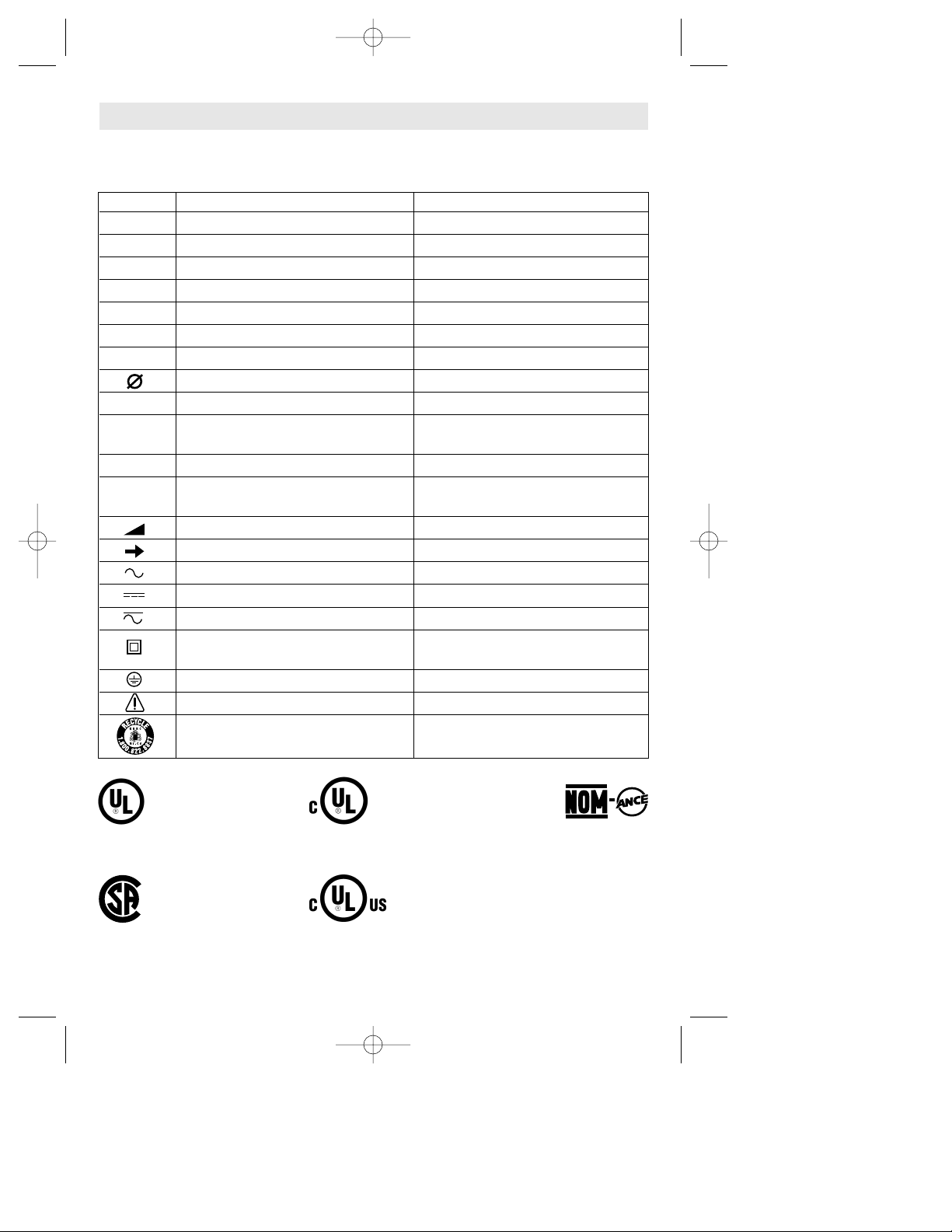
IMPORTANT: Some of the following symbols may be used on your tool. Please study them
and learn their meaning. Proper interpretation of these symbols will allow you to operate the
tool better and safer.
Symbol Name Designation/Explanation
V Volts Voltage (potential)
A Amperes Current
Hz Hertz Frequency (cycles per second)
W Watt Power
kg Kilograms Weight
min Minutes Time
s Seconds Time
Diameter Size of drill bits, grinding wheels, etc.
n
0
No load speed Rotational speed, at no load
.../min Revolutions or reciprocation per minute Revolutions, strokes, surface speed,
orbits etc. per minute
0 Off position Zero speed, zero torque...
1, 2, 3, ... Selector settings Speed, torque or position settings.
I, II, III, Higher number means greater speed
Infinitely variable selector with off Speed is increasing from 0 setting
Arrow Action in the direction of arrow
Alternating current Type or a characteristic of current
Direct current Type or a characteristic of current
Alternating or direct current Type or a characteristic of current
Class II construction Designates Double Insulated
Construction tools.
Earthing terminal Grounding terminal
Warning symbol Alerts user to warning messages
Ni-Cad RBRC seal Designates Ni-Cad battery recycling
program
Symbols
0
This symbol designates
that this tool is listed by
Underwriters Laboratories.
This symbol designates
that this tool is listed by
the Canadian Standards
Association.
This symbol designates
that this tool is listed to
Canadian Standards by
Underwriters Laboratories.
This symbol
designates
that
this tool
complies
to NOM
Mexican
Standards.
This symbol designates that
this tool is listed by
Underwriters Laboratories,
and listed to Canadian
Standards by Underwriters
Laboratories.
BM 2610925944 6-05 6/10/05 11:50 AM Page 6
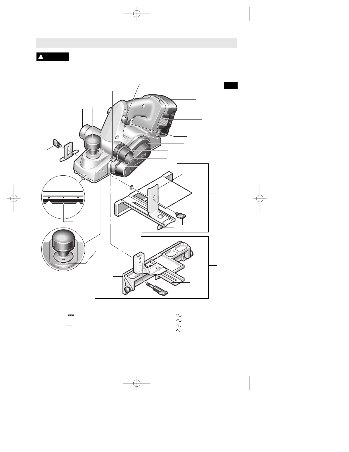
Functional Description and Specifications
Disconnect battery pack from tool or place the switch in the locked or off
position before making any assembly, adjustments or changing
accessories. Such preventive safety measures reduce the risk of starting the tool accidentally.
!
WARNING
WING
KNOB
RABBETING
DEPTH STOP
(OPTIONAL)
DEPTH
ADJUSTMENT
KNOB
CHIP EXHAUST
PORT
CHIP EXHAUST PORT
DEPTH
SCALE
PORT SELECTOR
LEVER
TRIGGER SWITCH
“LOCK-OFF”
BUTTON
FRONT SHOE
PIVOT
FENCE
ROUND
KNOB
GUIDE
BRACKET
WING KNOB
WING KNOB
FENCE
SCREW
DRIVE BELT COVER
CHAMFER
V-GROOVE
GUIDE
BRACKET
WIDTH
SCALE
DELUXE
ANGLE
FENCE
(OPTIONAL)
WING
KNOB
STANDARD
PARALLEL
WIDTH
GUIDE
FENCE
FIG. 1
THE CUTTING DEPTH
CHOICES ARE
APPROXIMATELY
1/16", 3/64", 1mm (•),
1/32", 1/64", & 1/128" (•)
BATTERY
RELEASE TABS
BATTERY PACK
SCREW
BC006 charger requires 12 V DC input
NOTE: ONLY USE CHARGERS LISTED ABOVE
Model Voltage No load Charger Voltage Battery
number rating speed number rating pack
53514 14.4 V n0 13,000/min BC001 thru 6 & BC016 120 V 60 Hz BAT040 & BAT038
BC130 & BC230 120 V 60 Hz BAT140 thru 159
53518 18 V n0 13,000/min BC003, 4, 6, & BC016 120 V 60 Hz BAT026 & BAT025
BC130 & BC230 120 V 60 Hz BAT160 thru 189
Cordless Planers
Maximum Capacities
Planing depth 0 - 1/16" (0 - 1.6mm)
Rabbeting depth 0 - 5/16" (0 - 8mm)
Cutting width 3-1/4" (82mm)
-7-
BM 2610925944 6-05 6/10/05 11:50 AM Page 7
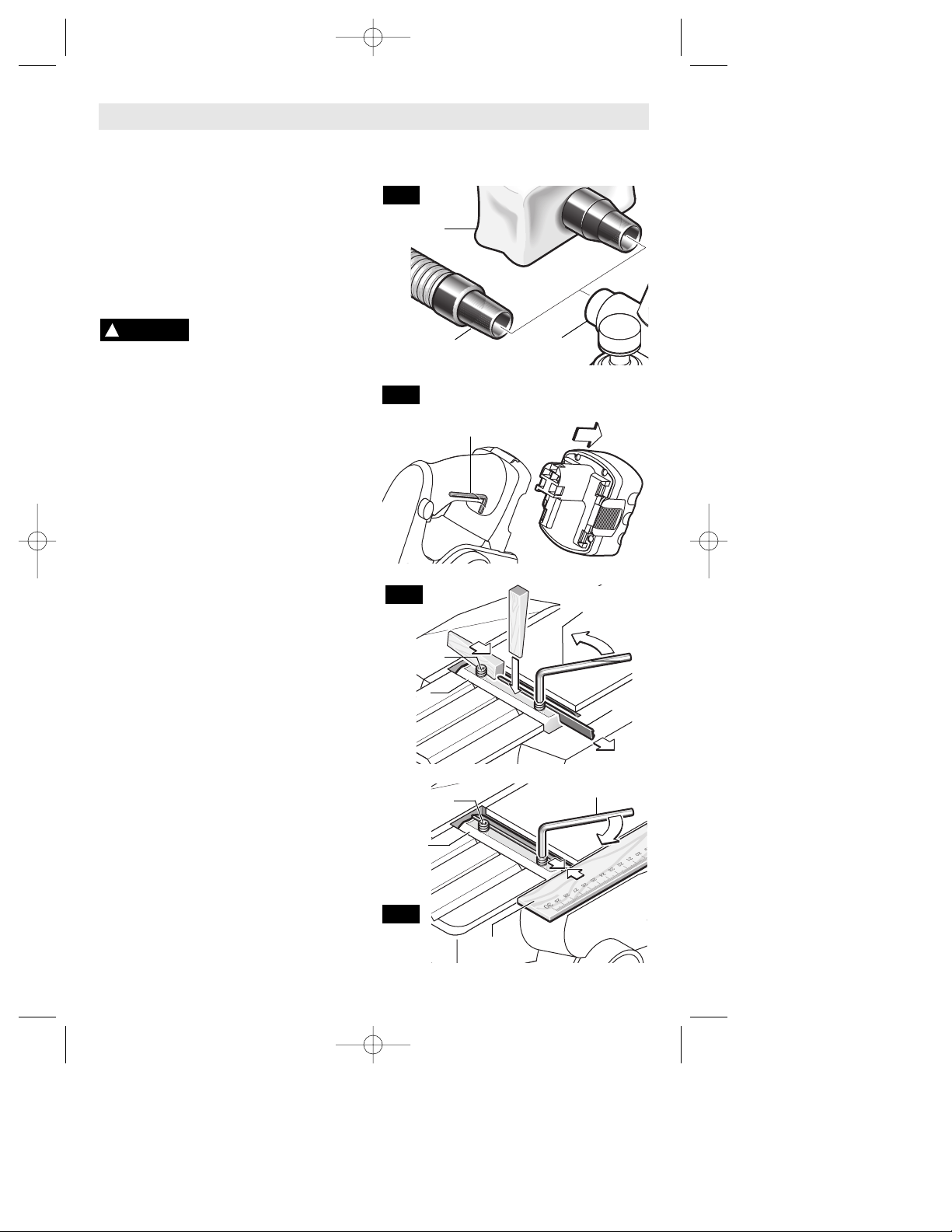
CHIP EXTRACTION
The planer comes with two chip exhaust ports,
which may be used with a chip bag or a shop
vacuum and vacuum connector (Fig.2) to
keep your work environment cleaner. The
chip bag or vacuum connector may be
attached to either end of the exhaust port.
Moving the port selector lever to position 1
(towards front of tool) discharges chips to the
left, while position 2 (towards rear of tool)
discharges chips to the right (Fig. 1)
PLANER BLADES
The planer blades are
sharp and fragile and must
be handled carefully to avoid injury to the
user or damage to the blades.
The planer blades have two cutting edges,
and may be reversed when one of the cutting
edges becomes dull or chipped.
Do not attempt to sharpen or use resharpened
used blades of any kind. Use only blades
designated for use with this model, because
other blades will cause vibration, decrease
perfomance and may not clamp securely in
blade holder.
BLADE WRENCH & STORAGE AREA
Your tool is equipped with a blade wrench that
is conveniently located in the handle base
where it is always handy and unlikely to get
lost or misplaced (Fig. 3).
REVERSING OR REPLACING BLADES
To reverse or replace the blade, loosen the
clamping screws with blade wrench. With the
screws loosened, slide the blade lengthwise
out of the cutter drum, taking care to keep
your fingers away from the sharp edges of the
blade (Fig. 4).
A piece of wood may be used for this purpose.
If the blade is gummed and difficult to remove,
you may clean the blade with mineral spirits,
lacquer thinner or alcohol.
Clean all surfaces before reinstalling the new
blade, as this will ensure an accurate blade
setting and proper tool performance.
BLADE ALIGNMENT
To ensure an even cut, it is important that the
blade is adjusted so that it aligns with the
outside edge of the front and rear shoes. This
alignment can be done as follows: place a
straight edge or a piece of wood along the
outside surface of the front shoe and rear
shoe, then slide the planer blade to just
contact the straight edge or wood (Fig.5).
Make sure the blade sits correctly in the
holder groove of the cutter drum.
You may then tighten the clamping screws
which secure the blade and your planer is
ready for use.
-8-
Assembly
FIG. 2
FIG. 4
FIG. 3
FIG. 5
CHIP BAG
(OPTIONAL)
EXHAUST
PORTS
VACUUM
CONNECTOR
BLADE
CLAMPING
SCREW
CUTTER
DRUM
CLAMPING
SCREW
BLADE WRENCH
2.5 MM BLADE
WRENCH
CUTTER
DRUM
STRAIGHT
EDGE
BLADE WRENCH &
STORAGE AREA
!
WARNING
BM 2610925944 6-05 6/10/05 11:50 AM Page 8
-9-
Operating Instructions
TRIGGER "ON/OFF" SWITCH
Hold the tool with both
hands while starting the
tool, since torque from the motor can
cause the tool to twist.
To turn tool "ON", depress the "Lock-OFF"
button and squeeze the trigger switch. To
turn the tool "OFF", release the trigger switch
which is spring loaded and will return to
"OFF" position automatically.
To increase switch life, do not turn switch on
and off while tool and drum are held against
a workpiece.
BRAKE
When the trigger is released it activates the
electrical brake to stop the blade quickly. This
feature is especially useful when making
repetitive cuts.
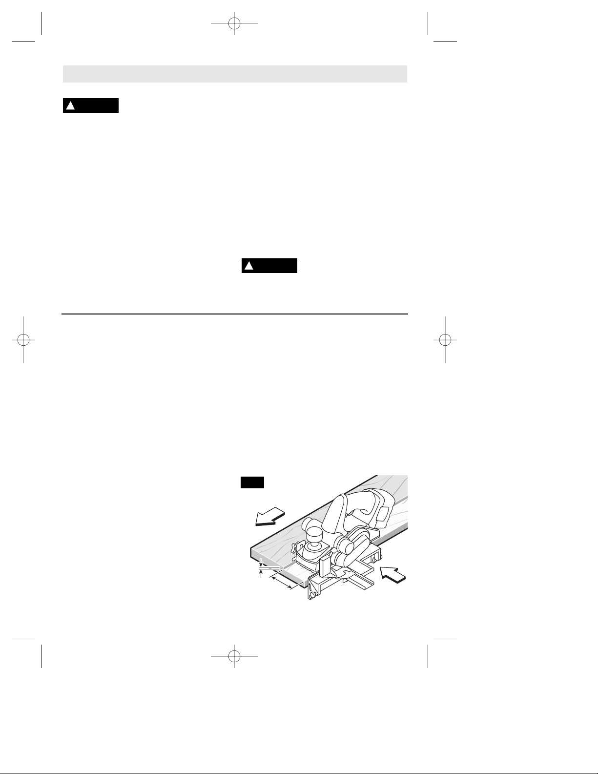
PLANING ACTION
Check that the workpiece is held in place
securely on your work surface, and standing
comfortably, hold the planer firmly with both
hands. With the planer fully adjusted, place
the front shoe on the workpiece, (be certain
that the cutter drum is not in contact with the
work) and start the planer as described
earlier. With pressure on the front shoe, and
the fence against the side of the work (to
control the width or angle,) feed the planer
steadily until the rear shoe fully engages the
workpiece. Now gradually transfer pressure
to the rear shoe, and continue planing to the
end of the cut. Feed the planer at a uniform
and reasonable rate, which does not put
excessive strain on the motor or blades, (do
not pull the planer back over the surface
already cut.) Use progressive cuts until you
are near the desired depth, and then readjust to a light cut for the final pass to obtain
a good surface finish.
The motor may stall if
improperly used or
overloaded. Reduce the pressure (feed
rate) or depth of cut to prevent possible
damage to the tool if the motor labors.
!
CAUTION
ADJUSTING DEPTH OF CUT
Proper cutting depth should be determined
according to the hardness, gumminess or
moisture content of the material being cut, as
well as the feed rate, and is largely a matter
of experience. Start with a light cut and
increase the depth setting if the plane moves
freely through the workpiece with no
excessive load on the motor. Do not change
depth of cut while planing.
The cutting depth is determined by the
difference in height between the adjustable
front shoe, and the fixed rear shoe of the
planer. As the front shoe is adjusted, it
retracts and exposes the blade, which can
then remove the desired amount from the
workpiece. The cutting depth is graduated
from 0 to 1/16 of an inch, and the "0"
indicates the blade is fully retracted.
Adjusting depth of cut: Rotate depth
adjustment knob until the indicator engages
the detent which indicates the desired cutting
depth on the depth scale (Fig. 1).
The planer may be set to cut any depth from
0 to 1/16 of an inch.
STANDARD PARALLEL WIDTH
GUIDE FENCE
The width guide fence can be used to cut
various desired widths (Fig. 1).
Installing the guide fence: Place the wing
knob through the appropriate hole in the
guide bracket and screw into the housing.
Securely tighten wing knob.
Setting the cutting width: Loosen wing knob
and slide the fence along the guide bracket
to the desired position. Securely tighten
wing knob. Be certain that the flat washer
(supplied) is fitted between the bottom of the
guide fence and wing knob or the guide
fence is likely to slip.
DELUXE ANGLE FENCE
The optional deluxe angle fence (Fig. 6) can
be used to cut various desired widths, with
the additional capability of guiding the planer
!
WARNING
82 mm
max
8 mm
max
FIG. 6
BM 2610925944 6-05 6/10/05 11:50 AM Page 9
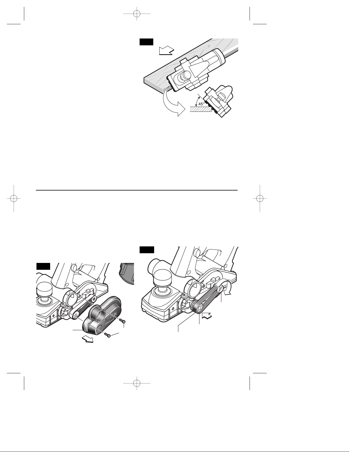
-10-
on any angle up to 45 degrees, to allow edge
chamfering (Fig. 7).
Installing the angle fence: Place the wing
knob through the appropriate hole in the
guide bracket and screw into the housing.
Securely tighten wing knob (Fig. 1).
Setting the cutting width: Loosen wing knob
and using the width scale, slide the fence
along the guide bracket to the desired
position. Securely tighten wing knob (Fig. 1).
Setting the cutting angle: Loosen round
knobs and pivot the fence to the desired
position. Securely tighten round knobs (Fig. 1).
Note that the adjustable front shoe contains
a chamfer V-groove, which will follow the
corner of a workpiece to allow easier
handling when using the deluxe angle/width
fence (Fig. 7).
RABBETING DEPTH STOP
The optional rabbeting depth stop accessory
(Fig. 1) allows the user to set any rabbeting
depth from 0 to 5/16 inch. For best results, it
is important that the blade be properly aligned
(See "BLADE ALIGNMENT"). The width of
the rabbet is controlled by the width fence.
The maximum cutting width is 3-1/4", and the
final depth is achieved by repetitive cutting
until the rabbeting depth guide contacts the
workpiece. The maximum rabbeting depth is
5/16"
Setting the rabbet depth: Loosen wing knob
and using the depth scale on the rabbeting
depth stop, set the desired rabbet depth.
Securely tighten wing knob.
FIG. 7
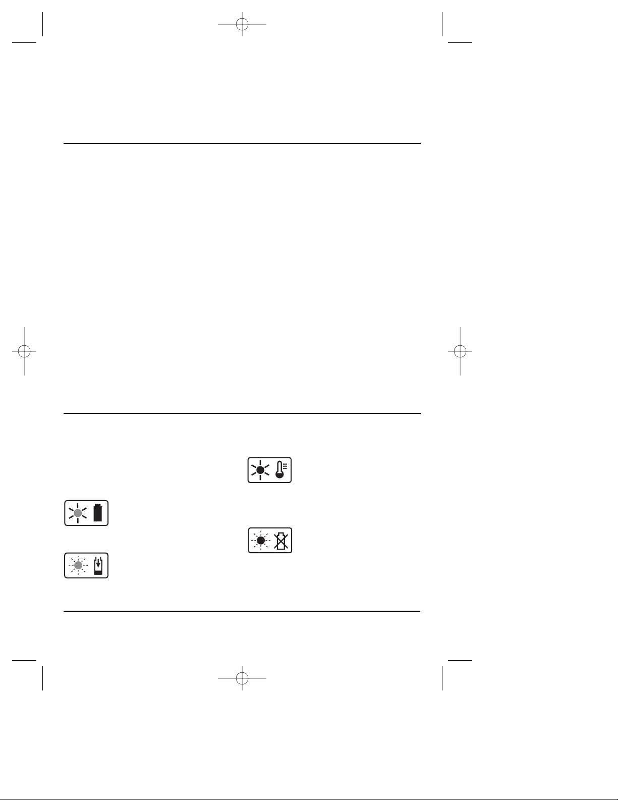
DRIVE BELT
The drive belt is a normal maintenance part
and should be inspected periodically for
wear. If the drive belt shows signs of drying
out, cracking or tearing, it should be
replaced. If the drive belt will not track
properly or comes off the pulleys, it should be
replaced.
Installing new drive belt: Loosen screws and
remove the drive belt cover (Fig. 8). Cut and
remove the worn drive belt. Before installing
the new drive belt, clean both pulleys
thoroughly. First place the new drive belt
onto the drive pulley then rotate clockwise
while pushing the belt onto the driven pulley.
Reinstall the drive belt cover and securely
tighten screws (Fig. 9).
FIG. 9
DRIVE
PULLEY
DRIVEN
PULLEY
DRIVE
BELT
DRIVE
BELT
COVER
SCREW
FIG. 8
BM 2610925944 6-05 6/10/05 11:50 AM Page 10
-11-
RELEASING AND INSERTING BATTERY PACK
Release battery pack from tool by pressing
on both sides of the battery release tabs and
pull downwards. Before inserting battery
pack, remove protective cap from battery
pack. To insert battery, align battery and slide
battery pack into tool until it locks into
position. Do not force.
1. The battery pack accepts only about 80%
of its maximum capacity with its first few
charge cycles. However, after the first few
charge cycles, the battery will charge to full
capacity.
2. The charger was designed to fast charge
the battery only when the battery
temperature is between 40˚F (4˚ C) and
105˚F (41˚C).
3. A substantial drop in operating time per
charge may mean that the battery pack is
nearing the end of its life and should be
replaced.
4. If you anticipate long periods (i.e. a month
or more) of non-use of your tool, it is best to
run your tool down until it is fully discharged
before storing your battery pack. After a long
period of storage, the capacity at first recharge
will be lower. Normal capacity will be restored
in two or three charge/discharge cycles.
Remember to unplug charger during storage
period.
5. If battery does not charge properly:
a. Check for voltage at outlet by plugging
in some other electrical device.
b. Check to see if outlet is connected to a
light switch which turns power “off” when
lights are turned off.
c. Check battery pack terminals for dirt.
Clean with cotton swab and alcohol if
necessary.
d. If you still do not get proper charging,
take or send tool, battery pack and charger
to your local Bosch Service Center. See
“Tools, Electric” in the Yellow Pages for
names and addresses.
Note: Use of chargers or battery packs not
sold by Bosch will void the warranty.
IMPORTANT CHARGING NOTES
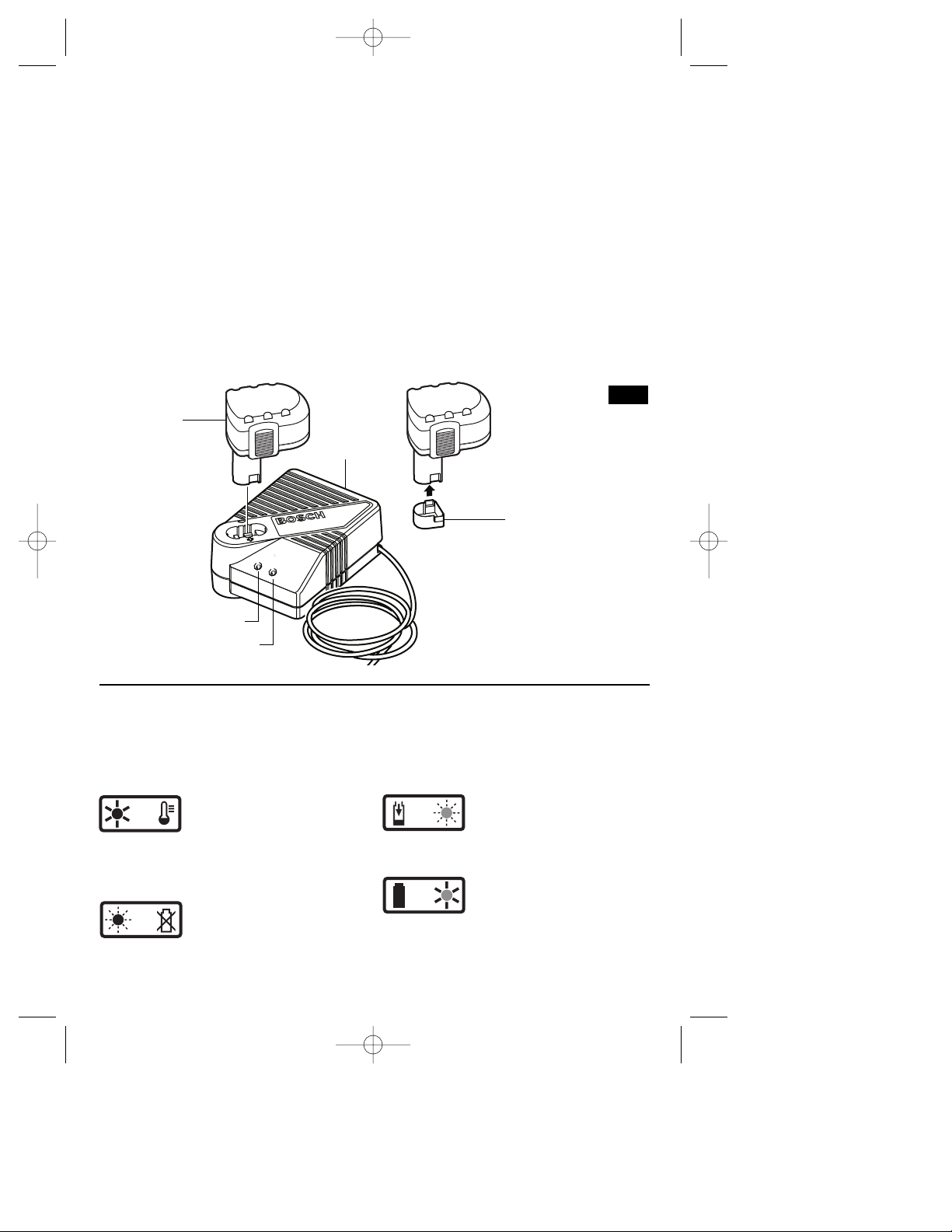
CHARGING BATTERY PACK (30 MINUTE SINGLE BAY-BC130)
INDICATORS, SYMBOLS AND MEANING
If the indicator lights are “OFF”, the charger
is not receiving power from power supply
outlet.
If the green indicator light is
“ON”, the charger is plugged in
but the battery pack is not
inserted, or the battery pack is fully charged
and is being trickle charged.
If the green indicator light is
“BLINKING”, the battery pack is
being fast-charged. Fastcharging will automatically stop when the
battery pack is fully charged.
If the red indicator light is “ON”,
the battery pack is too hot or
cold for fast-charging. The
charger will switch to trickle charge, until a
suitable temperature is reached, at which
time the charger will switch automatically to
fast-charging.
If the red indicator light is
“BLINKING”, the battery pack
cannot accept a charge or the
contacts of the charger or battery pack are
contaminated. Clean the contacts of the
charger or battery pack only as directed in
these operating instructions or those
supplied with your tool or battery pack.
BM 2610925944 6-05 6/10/05 11:50 AM Page 11
-12-
Plug charger cord into your standard power
outlet. Before inserting battery pack, remove
protective cap, then insert battery pack into
charger (Fig. 10).
The charger’s green indicator light will begin to
“BLINK”. This indicates that the battery is
receiving a fast charge. Fast-charging will
automatically stop when the battery pack is
fully charged.
When the indicator light stops “BLINKING”
(and becomes a steady green light) fast
charging is complete.
The battery pack may be used even though
the light may still be blinking. The light may
require more time to stop blinking depending
on temperature. When you begin the charging
process of the battery pack, a steady red light
could also mean the battery pack is too hot or
too cold.
The purpose of the green light is to indicate
that the battery pack is fast-charging. It does
not indicate the exact point of full charge. The
light will stop blinking in less time if the battery
pack was not completely discharged.
When charging several batteries in sequence,
the charge time may slightly increase.
When the battery pack is fully charged,
unplug the charger (unless you're charging
another battery pack) and slip the battery
pack back into the tool.
To prevent fire or injury when batteries are
not in tool or charger, always place protective
cap onto end of battery pack.
CHARGER
BATTERY
PACK
PROTECTIVE
CAP
GREEN LIGHT
RED LIGHT
FIG. 10
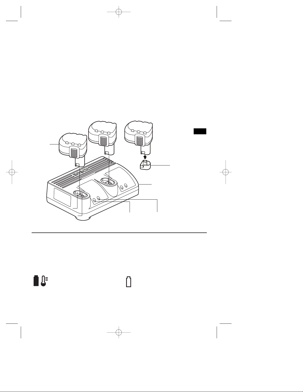
CHARGING BATTERY PACK (30 MINUTE DUAL BAY-BC230)
INDICATORS, SYMBOLS AND MEANING
If the indicator lights are “OFF”, the charger
is not receiving power from power supply
outlet.
If the red indicator light is
“ON”, the battery pack is too
hot or cold for fast-charging.
The charger will switch to trickle charge, until
a suitable temperature is reached, at which
time the charger will switch automatically to
fast-charging.
If the red indicator light is
“BLINKING”, the battery pack
cannot accept a charge or
the contacts of the charger or battery pack
are contaminated. Clean the contacts of the
charger or battery pack only as directed in
these operating instructions or those
supplied with your tool or battery pack.
If the green indicator light is
“BLINKING”, the battery pack
is being fast-charged. Fastcharging will automatically stop when the
battery pack is fully charged.
If the green indicator light is
“ON”, the charger is plugged
in but the battery pack is not
inserted, or the battery pack is fully charged
and is being trickle charged.
BM 2610925944 6-05 6/10/05 11:50 AM Page 12
-13-
Plug charger cord into your standard power
outlet. Before inserting battery pack, remove
protective cap, then insert battery pack into
charger (Fig. 11).
The charger’s green indicator light will begin to
“BLINK”. This indicates that the battery is
receiving a fast charge. Fast-charging will
automatically stop when the battery pack is
fully charged.
When the indicator light stops “BLINKING”
(and becomes a steady green light) fast
charging is complete.
The battery pack may be used even though
the light may still be blinking. The light may
require more time to stop blinking depending
on temperature. When you begin the
charging process of the battery pack, a
steady red light could also mean the battery
pack is too hot or too cold.
The purpose of the green light is to indicate
that the battery pack is fast-charging. It does
not indicate the exact point of full charge.
The light will stop blinking in less time if the
battery pack was not completely discharged.
When charging several batteries in
sequence, the charge time may slightly
increase.
When the battery pack is fully charged,
unplug the charger (unless you're charging
another battery pack) and slip the battery
pack back into the tool.
To prevent fire or injury when batteries are
not in tool or charger, always place protective
cap onto end of battery pack.
CHARGER
BATTERY
PACK
PROTECTIVE
CAP
FIG. 11
GREEN LIGHT
RED LIGHT
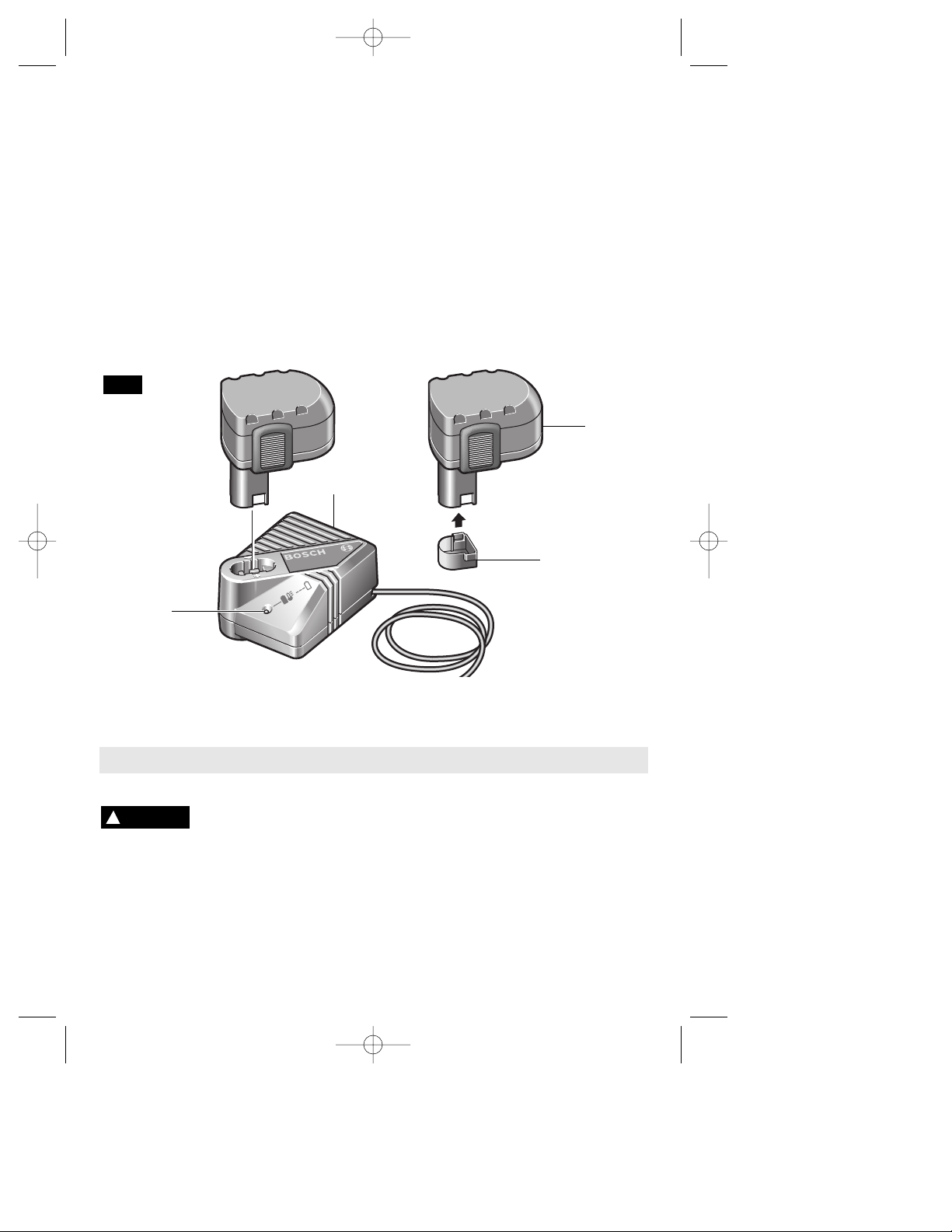
CHARGING BATTERY PACK (1 HOUR CHARGER)
INDICATORS, SYMBOLS AND MEANING
If the indicator lights are “OFF”, the charger
is not receiving power from power supply
outlet.
If the green indicator light is “ON”,
the charger is plugged in but the
battery pack is not inserted, or the
battery pack is fully charged and is being
trickle charged, or the battery pack is too hot
or cold for fast-charging. The charger will
switch to trickle charge, until a suitable
temperature is reached, at which time the
charger will switch automatically to fastcharging.
If the green indicator light is
“BLINKING”, the battery pack is
being fast-charged. Fast-charging
will automatically stop when the battery pack
is fully charged.
BM 2610925944 6-05 6/10/05 11:50 AM Page 13
Maintenance
Service
NO USER SERVICEABLE
PARTS INSIDE. Preventive
maintenance performed by unauthorized
personnel may result in misplacing of
internal wires and components which
could cause serious hazard. We recom-
mend that all tool service be performed by a
Bosch Factory Service Center or Authorized
Bosch Service Station. SERVICEMEN:
Disconnect tool and/or charger from power
source before servicing.
BATTERIES
Be alert for battery packs that are nearing
their end of life. If you notice decreased
tool performance or significantly shorter
running time between charges then it is time
to replace the battery pack. Failure to do so
!
WARNING
-14-
CHARGING BATTERY PACK (1 HOUR CHARGER)
Plug charger cord into your standard power
outlet. Before inserting battery pack, remove
protective cap, then insert battery pack into
charger (Fig. 12).
The charger’s green indicator will begin to
“BLINK”. This indicates that the battery is
receiving a fast charge. Fast-charging will
automatically stop when the battery pack is
fully charged.
When the indicator light stops “BLINKING”
(and becomes a steady green light) fast
charging is complete.
When you begin the charging process of the
battery pack, a steady green light could also
mean the battery pack is too hot or too cold.
The purpose of the light is to indicate that the
battery pack is fast-charging. It does not
indicate the exact point of full charge. The
light will stop blinking in less time if the
battery pack was not completely discharged.
When the battery pack is fully charged,
unplug the charger (unless you're charging
another battery pack) and slip the battery
pack back into the tool handle.
To prevent fire or injury when batteries are
not in tool or charger, always place protective
cap onto end of battery pack.
INDICATOR
LIGHT
CHARGER
BATTERY
PACK
PROTECTIVE
CAP
FIG. 12
BM 2610925944 6-05 6/10/05 11:50 AM Page 14
 Loading...