

Page 1
BM 1609929J64 12-05 12/12/05 4:07 PM Page 1
IMPORTANT: IMPORTANT : IMPORTANTE:
Read Before Using Lire avant usage Leer antes de usar
Operating/Safety Instructions
Consignes de fonctionnement/sécurité
Instrucciones de funcionamiento y seguridad
1800
1801
1803EVS
1806E
Call Toll Free for
Consumer Information
& Service Locations
1-877-BOSCH99 (1-877-267-2499) www.boschtools.com
For English Version Version française Versión en español
See page 2
Pour obtenir des informations
et les adresses de nos centres
de service après-vente,
appelez ce numéro gratuit
Voir page 14 Ver la página 26
Llame gratis para
obtener información
para el consumidor y
ubicaciones de servicio
Page 2

BM 1609929J64 12-05 12/12/05 4:07 PM Page 2
General Safety Rules
WARNING
!
all of the warnings listed below refers to your mains-operated (corded) power tool or batteryoperated (cordless) power tool.
Read all instructions. Failure to follow all instructions listed below may
result in electric shock, fire and/or serious injury.
The term “power tool” in
SAVE THESE INSTRUCTIONS
Work area safety
Keep work area clean and well lit.
Cluttered or dark areas invite accidents.
Do not operate power tools in explosive
atmospheres, such as in the presence of
flammable liquids, gases or dust.
tools create sparks which may ignite the dust
or fumes.
Keep children and bystanders away while
operating a power tool.
cause you to lose control.
Distractions can
Power
Electrical safety
Power tool plugs must match the outlet.
Never modify the plug in any way. Do not
use any adapter plugs with earthed
(grounded) power tools.
and matching outlets will reduce risk of
electric shock.
Avoid body contact with earthed or
grounded surfaces such as pipes,
radiators, ranges and refrigerators.
is an increased risk of electric shock if your
body is earthed or grounded.
Do not expose power tools to rain or wet
conditions.
increase the risk of electric shock.
Do not abuse the cord. Never use the cord
for carrying, pulling or unplugging the
power tool. Keep cord away from heat, oil,
sharp edges or moving parts.
entangled cords increase the risk of electric
shock.
When operating a power tool outdoors,
use an extension cord suitable for
outdoor use.
outdoor use reduces the risk of electric
shock.
Do not use AC only rated tools with a DC
power supply.
work, the electrical components of the AC
rated tool are likely to fail and create a
hazard to the operator.
Water entering a power tool will
Use of a cord suitable for
While the tool may appear to
Unmodified plugs
There
Damaged or
If operating the power tool in damp
locations is unavoidable a Ground Fault
Circuit Interrupter (GFCI) must be used to
supply the power to your tool.
personal protection devices like electrician’s
rubber gloves and footwear will further
enhance your personal safety.
GFCI and
Personal safety
Stay alert, watch what you are doing and
use common sense when operating a
power tool. Do not use a power tool while
you are tired or under the influence of
drugs, alcohol or medication.
inattention while operating power tools may
result in serious personal injury.
Use safety equipment. Always wear eye
protection.
mask, non-skid safety shoes, hard hat, or
hearing protection used for appropriate
conditions will reduce personal injuries.
Avoid accidental starting. Ensure the
switch is in the off-position before
plugging in.
finger on the switch or plugging in power
tools that have the switch on invites
accidents.
Remove any adjusting key or wrench
before turning the power tool on.
or a key left attached to a rotating part of the
power tool may result in personal injury.
Do not overreach. Keep proper footing
and balance at all times.
better control of the power tool in unexpected
situations.
Dress properly. Do not wear loose
clothing or jewelry. Keep your hair,
clothing and gloves away from moving
parts.
be caught in moving parts.
If devices are provided for the connection
of dust extraction and collection facilities,
ensure these are connected and properly
used.
related hazards.
Safety equipment such as dust
Carrying power tools with your
Loose clothes, jewelry or long hair can
Use of these devices can reduce dust-
-2-
A moment of
A wrench
This enables
Page 3

BM 1609929J64 12-05 12/12/05 4:07 PM Page 3
Keep handles dry, clean and free from oil
and grease.
control the power tool.
Slippery hands cannot safely
Power tool use and care
Do not force the power tool. Use the
correct power tool for your application.
The correct power tool will do the job better
and safer at the rate for which it was
designed.
Do not use the power tool if the switch
does not turn it on and off.
that cannot be controlled with the switch is
dangerous and must be repaired.
Disconnect the plug from the power
source and/or the battery pack from the
power tool before making any
adjustments, changing accessories, or
storing power tools.
measures reduce the risk of starting the
power tool accidentally.
Store idle power tools out of the reach of
children and do not allow persons
unfamiliar with the power tool or these
instructions to operate the power tool.
Power tools are dangerous in the hands of
untrained users.
Maintain power tools. Check for
misalignment or binding of moving parts,
breakage of parts and any other condition
that may affect the power tools operation.
If damaged, have the power tool repaired
before use.
poorly maintained power tools.
Many accidents are caused by
Any power tool
Such preventive safety
SAVE THESE INSTRUCTIONS
Keep cutting tools sharp and clean.
Properly maintained cutting tools with sharp
cutting edges are less likely to bind and are
easier to control.
Use the power tool, accessories and tool
bits etc., in accordance with these
i
nstructions and in the manner intended
for the particular type of power tool,
taking into account the working
conditions and the work to be performed.
Use of the power tool for operations different
from those intended could result in a
hazardous situation.
Use clamps or other practical way to
secure and support the workpiece to a
stable platform.
or against your body is unstable and may
lead to loss of control.
Holding the work by hand
Service
Have your power tool serviced by a
qualified repair person using only identical
replacement parts.
safety of the power tool is maintained.
Develop a periodic maintenance schedule
for your tool. When cleaning a tool be
careful not to disassemble any portion of
the tool since internal wires may be
misplaced or pinched or safety guard
return springs may be improperly
mounted.
gasoline, carbon tetrachloride, ammonia, etc.
may damage plastic parts.
Certain cleaning agents such as
This will ensure that the
Angle Grinder Safety Rules
Always use proper guard with grinding
wheel.
broken wheel fragments. When using
grinding wheel attachments, the guard must
always be attached to the tool and positioned
for maximum safety, so the least amount of
wheel is exposed from the side the tool is
being operated.
Use clamps or other practical way to
secure and support the workpiece to a
stable platform.
or against your body is unstable and may
lead to loss of control.
A guard protects operator from
Holding the work by hand
Accessories must be rated for at least the
speed recommended on the tool warning
label.
Wheels and other accessories running
over rated speed can fly apart and cause
injury. Grinding wheels or any other
accessory must have a maximum safe
operating speed greater than the “no load
RPM” marked on the tool’s nameplate.
Hold tool by insulated gripping surfaces
when performing an operation where the
cutting tools may contact hidden wiring
or its own cord.
will make exposed metal parts of the tool
“live” and shock the operator.
Contact with a “live” wire
-3-
Page 4

BM 1609929J64 12-05 12/12/05 4:07 PM Page 4
Always use auxiliary handle for maximum
control over torque reaction or kick-back.
O
peration of the grinder without the side
h
andle could cause loss of control of the
grinder, resulting in possible serious personal
injury.
Before using a grinder or installing a new
wheel, inspect the grinding wheel for chips
and cracks. Remove bad wheels
immediately. Run the tool at no load for
one minute, holding the tool in the
direction away from people.
flaws will normally break apart during this
time.
Carefully handle both the tool and
individual grinding wheels to avoid
chipping or cracking. Install a new wheel if
tool is dropped while grinding. Do not use
a wheel that may be damaged.
from a wheel that bursts during operation will
fly away at great velocity possibly striking you
or bystanders.
Do not use grinding wheel that is larger
than the maximum recommended size for
your tool, or worn down damaged wheels
from larger grinders.
large angle sander/grinders are not suitable
for the high speed of a small angle
sander/grinder, these wheels may easily burst
and the fragments strike you or bystanders.
Do not use depressed hub grinding wheels
for cut-off operations.
wheels or type 27 wheels are not intended for
side loading and may shatter under overload.
Do not use this tool with “Woodcarving”
Such blades create frequent kick-back
blade.
and loss of control.
Wear proper apparel while using a
sander/grinder.
goggles, dust mask, leather gloves and shop
apron capable of stopping small wheel or
workpiece fragments.
Position the cord clear of the spinning
grinding wheel or any other sanding
accessory. Do not wrap the cord around
your arm or wrist.
have the cord wrapped around your arm or
wrist it may entrap you and cause injury.
Wheels intended for
Face shield or at least safety
If you lose control and
Wheels with
Fragments
Depressed hub
Avoid bouncing and snagging the wheel,
especially when working corners, sharp
e
dges etc.
k
ick-back.
Regularily clean the tool’s air vents by
compressed air.
powdered metal inside the motor housing may
cause electrical failures.
Do not grind or sand near flammable
materials.
these materials.
This tool can be converted to a sander.
When grinding is resumed the proper
guard and wheel flanges MUST be
reinstalled before proceeding with
grinding. The guard must always be
attached to the tool and positioned for
maximum safety, so the least amount of
wheel is exposed from the side the tool is
being operated.
cannot be used for most sanding operations
or for wire brushing.
When sanding, do not use oversized
sanding disc.
beyond the sanding pad causing snagging,
tearing of the disc or kick-back. Extra paper
extending beyond the sanding pad can also
cause serious lacerations.
!
grinding, drilling, and other construction
activities contains chemicals known to
cause cancer, birth defects or other
reproductive harm. Some examples of
these chemicals are:
• Lead from lead-based paints,
• Crystalline silica from bricks and cement and
other masonry products, and
• Arsenic and chromium from chemicallytreated lumber.
Your risk from these exposures varies,
depending on how often you do this type of
work. To reduce your exposure to these
chemicals: work in a well ventilated area, and
work with approved safety equipment, such as
those dust masks that are specially designed
to filter out microscopic particles.
T
his can cause loss of control and
Excessive accumulation of
Sparks from the wheel could ignite
The grinding wheel guard
Larger sanding disc will extend
WARNING
Some dust created by
power sanding, sawing,
-4-
Page 5
A
0
A
A
0
A
BM 1609929J64 12-05 12/12/05 4:07 PM Page 5
Symbols
IMPORTANT: Some of the following symbols may be used on your tool. Please study them
and learn their meaning. Proper interpretation of these symbols will allow you to operate the
tool better and safer.
Symbol Name Designation/Explanation
V Volts Voltage (potential)
A Amperes Current
Hz Hertz Frequency (cycles per second)
W Watt Power
kg Kilograms Weight
min Minutes Time
s Seconds Time
Diameter Size of drill bits, grinding wheels, etc.
n
.../min Revolutions or reciprocation per minute Revolutions, strokes, surface speed,
0 Off position Zero speed, zero torque...
1, 2, 3, ... Selector settings Speed, torque or position settings.
I, II, III, Higher number means greater speed
No load speed Rotational speed, at no load
0
orbits etc. per minute
Infinitely variable selector with off Speed is increasing from 0 setting
Arrow Action in the direction of arrow
Alternating current Type or a characteristic of current
Direct current Type or a characteristic of current
Alternating or direct current Type or a characteristic of current
Class II construction
Earthing terminal Grounding terminal
Warning symbol Alerts user to warning messages
Ni-Cad RBRC seal Designates Ni-Cad battery recycling
Designates Double Insulated
Construction tools.
program
This symbol designates
that this tool is listed by
Underwriters Laboratories.
This symbol designates
that this tool is listed by
the Canadian Standards
Association.
This symbol designates
that this tool is listed to
Canadian Standards by
Underwriters Laboratories.
This symbol designates that
this tool is listed by
Underwriters Laboratories,
and listed to Canadian
Standards by Underwriters
Laboratories.
This symbol
designates
that
this tool
complies
to NOM
Mexican
Standards.
-5-
Page 6
BM 1609929J64 12-05 12/12/05 4:07 PM Page 6
Functional Description and Specifications
WARNING
!
Disconnect the plug from the power source before making any
a
ssembly, adjustments or changing accessories.
measures reduce the risk of starting the tool accidentally.
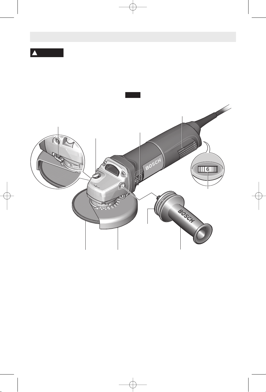
Angle Grinders
FIG. 1
RELEASE / ADJUSTMENT
GUARD
BUTTON
SPINDLE LOCK
SWITCH
BUTTON
S
uch preventive safety
VENTILATION
OPENINGS
VARIABLE SPEED
WITH DIAL SETTING
(Model 1803EVS only)
VIBRATION
CONTROL
GRINDING
WHEEL
WHEEL
GUARD
SIDE HANDLE
Model number 1800 1801 & 1803EVS 1806E
Max. wheel diameter 4 1/2" (115mm) 5" (125mm) 6" (150mm)
Spindle thread 5/8"-11 UNC 5/8 "-11 UNC 5/8 "-11 UNC
Max. wire wheel 4" Dia. 4" Dia. 4" Dia.
Max. wire cup brush 3" Dia. 3" Dia. 3" Dia.
Max. sanding disc 4 1/2" Dia. 5" Dia. 6" Dia.
Max. cut off wheel 4 1/2" Dia. 5" Dia. 6" Dia.
Max. dry diamond wheel 4 1/2" Dia. 5" Dia. 6" Dia.
NOTE: For tool specifications refer to the nameplate on your tool.
-6-
Page 7

BM 1609929J64 12-05 12/12/05 4:07 PM Page 7
Assembly
T
W
HEEL GUARD INSTALLATION
WARNING
!
Wheel guard must be
attached when using disc
grinding wheels. Always keep wheel guard
between you and your work while grinding.
The position of the guard can be adjusted to
accommodate the operation being performed.
To attach wheel guard DISCONNECT tool
from power source.
Position wheel guard on spindle neck so that
the arrow on guard lines up with the arrow on
the spindle neck. Rotate wheel guard
clockwise 90º until it clicks in place (Fig. 2).
TO ADJUST GUARD: depress guard release
button (Fig. 1), rotate guard to desired position,
release button and let it click in place.
O REMOVE GUARD: Depress release button,
rotate guard until arrow on guard lines up with
arrow on spindle neck, and remove guard from
spindle neck.
WHEEL
GUARD
SPINDLE
NECK
FIG. 2
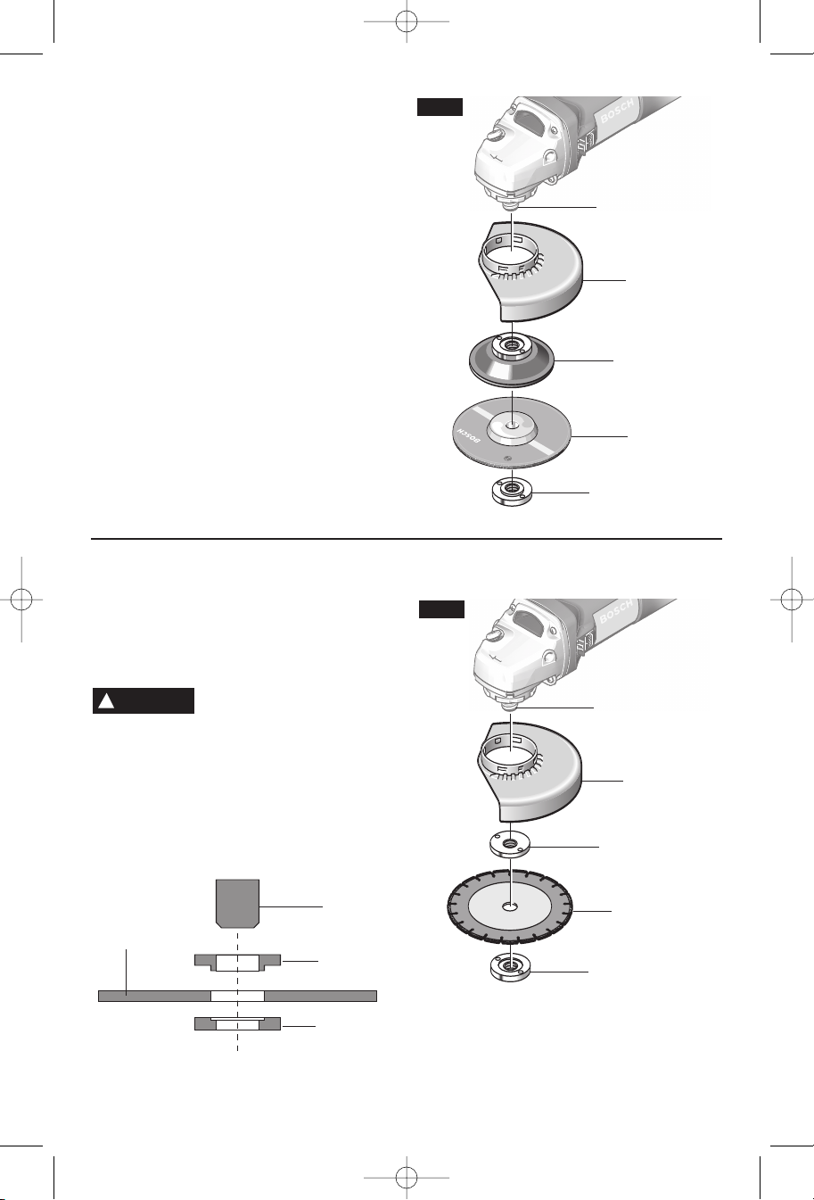
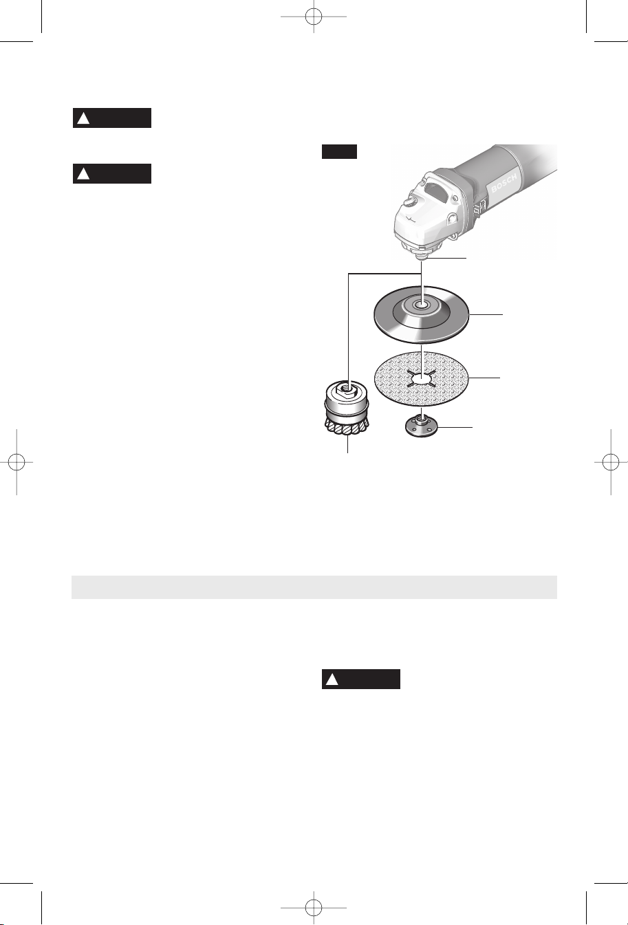
LOCK NUT AND BACKING FLANGE
Your tool is equipped with a threaded spindle
for mounting accessories. Always use the
supplied lock nut (and backing flange) that
has same thread size as spindle.
Disc Grinding Wheel Assembly
(Models 1800, 1801 & 1803EVS only)
Disconnect tool from power source. Be sure
that wheel guard is in place for grinding.
Place BACKING FLANGE and GRINDING
WHEEL on the spindle. Thread on the lock
nut and tighten nut using the supplied lock
nut wrench, while holding the spindle lock in
(Fig. 3).
SPINDLE
GRINDING
WHEEL
BACKING
FLANGE
LOCK NUT
The side handle used to guide and balance the
SIDE HANDLE
tool can be threaded into the front housing on
either side of the tool, depending on personal
preference and comfort. Use the side handle
for safe control and ease of operation.
FIG. 3
SPINDLE
WHEEL
GUARD
BACKING
FLANGE
GRINDING
WHEEL
LOCK NUT
-7-
Page 8
BM 1609929J64 12-05 12/12/05 4:07 PM Page 8
Disc Grinding Wheel Assembly
Disconnect tool from power source. Be sure
that wheel guard is in place for grinding.
When using spin-on grinding wheels, thread
directly onto the spindle.
When using mounting wheels, thread
BACKING FLANGE onto spindle, then place
GRINDING WHEEL on the spindle. Thread
on the lock nut and tighten nut using a lock
nut wrench provided with adapter kit, while
holding the spindle lock in (Fig. 4).
TO REMOVE: Reverse procedure.
(Model 1806 only)
Masonry Cutting Wheel Assembly
For cutting masonry materials like brick, tile,
stone, etc., it is best to use a dry diamond
cutting wheel. Use only lock nut and flange
with equal diameters. The wheel guard must
be used with a dry diamond cutting wheel.
WARNING
!
cutting.
Disconnect tool from power source. Be sure
that wheel guard is in place for grinding.
Place BACKING FLANGE and DRY
DIAMOND WHEEL on the spindle. Thread
on the lock nut and tighten nut using the
supplied lock nut wrench, while holding the
spindle lock in (Fig. 5).
Do not use water or other
cooling fluid with this tool for
FIG. 4
SPINDLE
WHEEL
GUARD
BACKING
FLANGE
GRINDING
WHEEL
LOCK NUT
TO REMOVE: Reverse procedure.
FIG. 5
SPINDLE
WHEEL
GUARD
BACKING
FLANGE
DRY
DIAMOND
WHEEL
SPINDLE
BACKING
FLANGE
LOCK NUT
DRY
DIAMOND
WHEEL
LOCK NUT
When cutting, make only small passes
through workpiece at a time. Be aware that
“Kickback” can occur at any time. Keep both
hands on tool for maximum control.
-8-
Page 9
BM 1609929J64 12-05 12/12/05 4:07 PM Page 9
Sanding Accessories Assembly
BACKING PAD
WARNING
!
safe operating speed is not exceeded by the
nameplate speed of the tool.
WARNING
!
operations. Always reinstall wheel guard
when converting back to grinding operations.
TO INSTALL BACKING PAD AND
Disconnect tool from power source. Set the
tool on its top side (spindle up). Place the
rubber backing pad onto the spindle shaft.
Center the sanding disc on top of the
backing pad. Insert the lock nut through the
disc and thread onto the spindle as far as
you can with your fingers. Press in the
spindle lock, then tighten the backing pad
securely with lock nut wrench (Fig. 6).
TO REMOVE BACKING PAD AND
Disconnect tool from power source. Using
the lock nut wrench unscrew the nut from the
spindle, while holding spindle lock in.
Before assembling wire brush to this tool,
disconnect from the power source. Wire
Before attaching a backing
pad be sure its maximum
Wheel guard may not be
used for most sanding
SANDING DISC
SANDING DISC
WIRE BRUSH ASSEMBLY
brushes are equipped with their own
threaded hub, simply thread on to spindle
(
Fig. 6). Be sure to seat against shoulder
b
efore turning tool “ON”.
FIG. 6
S
PINDLE
BACKING
PAD
SANDING
DISC
LOCK NUT
WIRE
BRUSH
Operating Instructions
SLIDE ON-OFF SWITCH WITH LOCK
The tool is switched “ON” by the switch
button located at the side of the motor
housing. The switch can be locked in the
“ON” position, a convenience for long
grinding operations.
TO TURN THE TOOL “ON” without locking it,
slide the switch button forward by applying
pressure ONLY at the REAR portion of the
button. When pressure is released the switch
button will snap to “OFF” position.
TO LOCK THE SWITCH “ON”, slide the
switch button forward and press “IN” the
FRONT portion.
TO UNLOCK THE SWITCH, simply press
and release the REAR portion of the button.
Switch is spring loaded and will snap back
automatically.
WARNING
!
torque from the motor can cause the tool to twist.
Start the tool before applying to work and let
the tool come to full speed before contacting
the workpiece. Lift the tool from the work
before releasing the switch. DO NOT turn the
switch “ON” and “OFF” while the tool is
under load; this will greatly decrease the
switch life.
Hold the tool with both hands
while starting the tool, since
-9-
Page 10
BM 1609929J64 12-05 12/12/05 4:07 PM Page 10
ELECTRONIC FEEDBACK CIRCUITRY (EFC)
(Models 1803EVS & 1806E only)
The internal electronic feedback system
provides a "soft start", which will reduce the
stresses that occur from a high torque start.
The system also helps to keep the no load
speed virtually constant between no-load and
l
oad conditions.
KICKBACK STOP
Your tool is equipped with a kickback stop
feature. This feature shuts of the tool
automatically if the tool stalls, or the wheel
encounters excessive force. To resume
operation, TURN ON/OFF SWITCH TO THE
OFF POSITION, THEN RESTART THE
TOOL.
RESTART PROTECTION
The restart protection feature was designed
to help prevent accidental startups after the
power has been interrupted. To resume
operation if this occurs, TURN ON/OFF
SWITCH TO THE OFF POSITION, THEN
RESTART THE TOOL.
OVERLOAD PROTECTION
(Models 1803EVS & 1806E only)
Your tool is equipped with overload
protection to protect the motor. If the tool
stops during operation TURN OFF SWITCH
IMMEDIATELY and allow the motor to cool
for about 30 seconds by running at no-load.
If the overload protection stops the tool
repeatedly, excessive force is causing the
tool to overload. Don't press so hard and let
the tool do the work.
V
ARIABLE SPEED WITH DIAL SETTING
(1803EVS ONLY)
Your tool is also equipped with a variable
speed dial. The grinder’s RPM can be preset
from zero to maximum nameplate rated RPM
by rotating the dial on the motor housing. If
tool is running at a set speed for extended
periods of time, it may be necessary to run
the tool at no- load full speed to cool the motor.
D
ial Setting Application
Approx. RPM Material Attachment
Polishing Plastic Lambswool bonnet
1 or buffing disc.
(2800)
2-3 Solid wood & Sanding disc
(5300-7500) paint removal
3
(7500) Removing rust Sanding disc
4-6 Grinding metal Grinding disc
(8800-11000) or stone
6
(11000) Cutting stone Cutting disc
Precision grinding Grinding disc
of metal tools
Brushing wood
from metal
Roughing metal
felt polishing disc,
Cup brush
Roughing disc
Grinding Operations
SELECTING GRINDING WHEELS
WARNING
!
maximum safe operating speed is not
exceeded by the nameplate speed of the
grinder. Do not exceed the recommended
wheel diameter.
Grinding wheels should be carefully selected
in order to use the grinder most efficiently.
Wheels vary in type of abrasive, bond,
hardness, grit size and structure. The correct
type of wheel to use is determined by the job.
Use disc grinding wheels for fast grinding of
structural steel, heavy weld beads, steel
casting, stainless steel and other ferrous
metals.
Before using a grinding
wheel, be certain that its
DISC GRINDING WHEELS
Efficient grinding is achieved by controlling
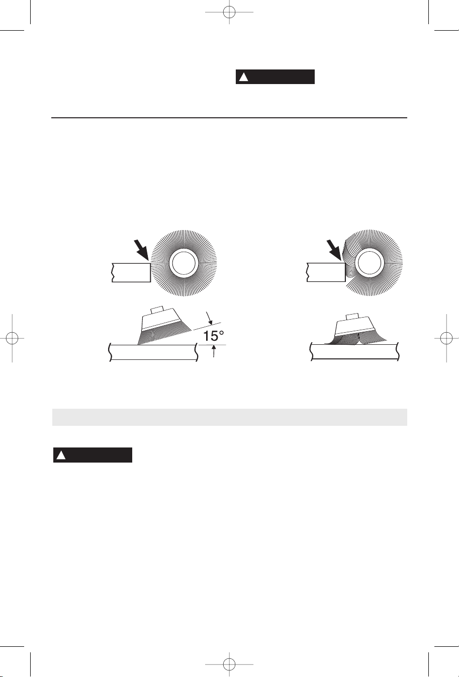
GRINDING TIPS
the pressure and keeping the angle between
wheel and workpiece at 10° to 15°. If the
wheel is flat, the tool is difficult to control. If
the angle is too steep, the pressure is
concentrated on a small area causing
burning to the work surface.
!
WARNING
Excessive or sudden pres-
sure on the wheel will slow
grinding action and put dangerous stresses
on the wheel.
When grinding with a new wheel be certain
to grind while pulling tool backwards until
wheel becomes rounded on its edge. New
wheels have sharp corners which tend to
“bite” or cut into workpiece when pushing
forward.
-10-
Page 11
BM 1609929J64 12-05 12/12/05 4:07 PM Page 11
Sanding Operations
SELECTING SANDING DISC
Sanding discs are made of extremely hard
and sharp aluminum oxide grits, phenol-resin
bonded to a sturdy fiber backing for fast
heavy-duty service and long life. The discs
vary as to size and spacing of the abrasive
grits. OPEN COAT (type H) — used for soft
materials and on paint or varnish. CLOSED
COAT (type K) —used for metal, hardwood,
stone, marble and other materials.
Sanding discs range in grit from 16 (very
coarse) to 180 (very fine). To obtain best
results, select sanding discs carefully. Many
jobs require the use of several grit sizes and
SANDING TIPS
For best results, tilt the Disc Sander at a 10°
to 15° angle while sanding so that only about
1" of the surface around the edge of the disc
contacts the work.
WARNING
!
If the disc (accessory) is held
flat or the back edge of the
disc comes in contact with the work, a violent
thrust to the side may result.
If sander is tilted too much, sanding action
will be too great and a rough cut surface or
gouging and snagging will result.
Guide the Disc Sander with crosswise
strokes. Be careful not to hold the sander in
one spot too long. Do not use a circular
motion, as this makes swirl marks. Test
before use on scrap stock.
Do not force or apply pressure when
sanding. Use only the weight of the tool for
pressure. Excess pressure actually slows the
tool down. If faster stock removal is desired,
change to a coarser grit disc.
Remove gummy paint from metal with an
“open coat” disc. Sand until sparks start to
at times both “open coat and closed coat”
discs are required to get the job done faster.
See chart for application examples.
peration:Refinishing painted wood or metal surfaces.
O
REMARKS GRIT
To remove paint and to smooth Coarse
urface irregularities. 16-24-30
s
o smooth Medium
T
he rough sanding. 36-50-80
t
o remove scratches left by Fine
T
revious discs. 100-120
p
To smooth surfaces for painting, Very Fine
polishing or waxing. 1
50-180
appear, then stop and change to a “closed
coat” disc to remove any remaining paint.
SANDING WOOD
When sanding wood the direction of the disc
motion at the contact point should parallel the
grain as much as possible. The rapid cut of
discs and the swirl type scratch pattern they
occasionally create generally prohibit their
use for producing the final finish.
Scratches and circular marks are usually the
result of using too coarse a grit. When
changing to a finer grit, move across the
sanding lines that were made by a previous
coarser disc.
SANDING METAL
When sanding automobiles or appliances,
wipe the metal clean with a non-flammable
solvent or commercial cleaner to remove all
wax and grease. By doing this first, the
sanding discs will sand better and last longer.
For heavy duty work, use a coarse grit disc
first. Follow-up with a medium grit to remove
scratches. To produce smooth finish, use fine
grit disc.
-11-
Page 12
BM 1609929J64 12-05 12/12/05 4:07 PM Page 12
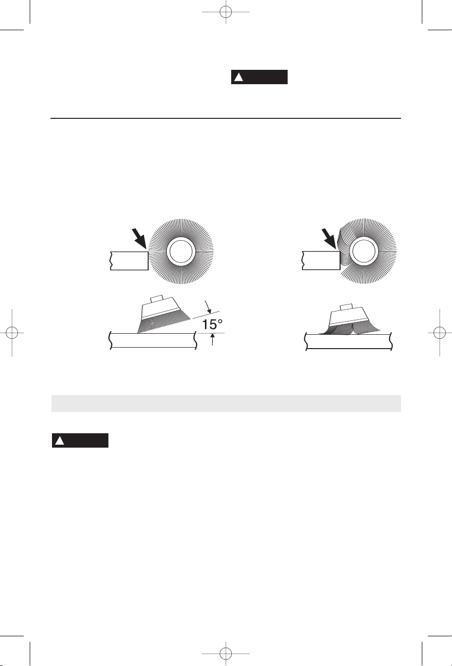
Wire Brush Operations
Wire brushes are intended to “clean”
structural steel, castings, sheet metal, stone
and concrete. They are used to remove rust,
s
cale and paint.
!
WARNING
when working corners, sharp edges etc. This
c
an cause loss of control and kick-back.
Avoid bouncing and snagging
the wire brush, especially
1. Remember, the tips of a wire brush do the
BRUSHING PRESSURE
work. Operate the brush with the lightest
pressure so only the tips of the wire come in
contact with the work.
2. If heavier pressures are used, the wires
will be overstressed, resulting in a wiping
CORRECT:
Wire tips doing
the work.
Maintenance
action; and if this is continued, the life of the
brush will be shortened due to wire fatigue.
3. Apply the brush to the work in such a way
that as much of the brush face as possible is
in full contact with the work. Applying the side
or edge of the brush to the work will result in
wire breakage and shortened brush life.
INCORRECT:
Excessive
pressure can
cause wire
breakage.
Service
WARNING
!
personnel may result in misplacing of
internal wires and components which
could cause serious hazard.
recommend that all tool service be performed
by a Bosch Factory Service Center or Authorized Bosch Service Station.
Your Bosch tool has been properly lubricated
and is ready to use. It is recommended that
tools with gears be regreased with a special
gear lubricant at every brush change.
Preventive maintenance
performed by unauthorized
We
TOOL LUBRICATION
The brushes and commutator in your tool
CARBON BRUSHES
have been engineered for many hours of
dependable service. To maintain peak
efficiency of the motor, we recommend every
two to six months the brushes be examined.
Only genuine Bosch replacement brushes
specially designed for your tool should be used.
BEARINGS
After about 300-400 hours of operation, or at
every second brush change, the bearings
should be replaced at Bosch Factory Service
Center or Authorized Bosch Service Station.
Bearings which become noisy (due to heavy
load or very abrasive material cutting) should
be replaced at once to avoid overheating or
motor failure.
-12-
Page 13
BM 1609929J64 12-05 12/12/05 4:07 PM Page 13
Cleaning
WARNING
!
the power supply before cleaning or
performing any maintenance.
be cleaned most effectively with compressed
dry air.
Always wear safety goggles when
cleaning tools with compressed air.
To avoid accidents always
disconnect the tool from
The tool may
Extension Cords
!
WARNING
adequate size conductors that is capable
of carrying the current necessary for your
tool must be used.
excessive voltage drop, loss of power or
overheating. Grounded tools must use 3wire extension cords that have 3-prong plugs
and receptacles.
NOTE: The smaller the gauge number, the
heavier the cord.
If an extension cord is
necessary, a cord with
This will prevent
Ventilation openings and switch levers must
be kept clean and free of foreign matter. Do
n
ot attempt to clean by inserting pointed
objects through openings.
CAUTION
!
plastic parts.
Certain cleaning agents
and solvents damage
Some of these are: gasoline,
carbon tetrachloride, chlorinated cleaning
solvents, ammonia and household detergents
that contain ammonia.
RECOMMENDED SIZES OF EXTENSION CORDS
120 VOLT ALTERNATING CURRENT TOOLS
Tool’s
Ampere
Rating
3-6
6-8
8-10
10-12
12-16
C
ord Size in A.W.G.
C
ord Length in Feet
25 50 100 150 15 30 60 120
18 16 16 14 0.75 0.75 1.5 2.5
18 16 14 12 0.75 1.0 2.5 4.0
18 16 14 12 0.75 1.0 2.5 4.0
16 16 14 12 1.0 2.5 4.0 —
14 12 — — — — — —
Wire Sizes in mm
C
ord Length in Meters
2
Accessories
* Wheel guard * Lock nut
* Grinding wheel * Backing flange
* Side handle
(*= standard equipment)
(**= optional accessories)
* Lock nut wrench
-13-
Page 14

BM 1609929J64 12-05 12/12/05 4:07 PM Page 14
Consignes générales de sécurité
!
AVERTISSEMENT
de blessures corporelles graves. Dans toutes les mises en garde ci-dessous, le terme « outil électroportatif »
se rapporte à des outils branchés sur le secteur (avec fil) ou à des outils alimentés par piles (sans fil).
Veuillez lire et comprendre toutes les consignes. Si on n'observe pas toutes les
consignes décrites ci-dessous, il y a risque de choc électrique, d’incendie et/ou
CONSERVEZ CES CONSIGNES
Sécurité du lieu de travail
Maintenez le lieu de travail propre et bien éclairé.
Les risques d’accident sont plus élevés quand on
travaille dans un endroit encombré ou sombre.
N’utilisez pas d’outils électroportatifs dans des
atmosphères explosives, comme par exemple en
présence de gaz, de poussières ou de liquides
inflammables. Les outils électroportatifs produisent
des étincelles qui risquent d’enflammer les poussières
ou les vapeurs.
Éloignez les enfants et les visiteurs quand vous vous
servez d’un outil électroportatif.
perte de contrôle si on vous distrait.
Vous risquez une
Sécurité électrique
Les fiches des outils électroportatifs doivent
correspondre à la prise. Il ne faut absolument jamais
modifier la fiche. N’utilisez pas d’adaptateur de prise
avec des outils électroportatifs munis d’une fiche de
terre. Le risque de choc électrique est moindre si on
utilise une fiche non modifiée sur une prise qui lui
correspond.
Évitez tout contact du corps avec des surfaces reliées
à la terre tels que tuyaux, radiateurs, gazinières ou
réfrigérateurs. Le risque de choc électrique augmente
si votre corps est relié à la terre.
N’exposez pas les outils électroportatifs à la pluie ou
à l’humidité. Si de l’eau pénètre dans un outil
électroportatif, le risque de choc électrique augmente.
Ne maltraitez pas le cordon. Ne vous en servez
jamais pour transporter l’outil électroportatif, pour le
tirer ou pour le débrancher. Éloignez le cordon de la
chaleur, des huiles, des arêtes coupantes ou des
pièces mobiles. Les cordons abîmés ou emmêlés
augmentent les risques de choc électrique.
Si vous utilisez un outil électroportatif à l’extérieur,
employez une rallonge conçue pour l’extérieur.
rallonges sont faites pour l’extérieur et réduisent le
risque de choc électrique.
N’utilisez pas un outil conçu uniquement pour le C.A.
sur une alimentation en C.C. Même si l’outil semble
fonctionner, les composants électriques d’un outil prévu
pour le C.A. tomberont probablement en panne et
risquent de créer un danger pour l’utilisateur.
S’il est nécessaire d’utiliser l’outil dans un lieu
humide, il faut l’alimenter par l’intermédiaire d’un
disjoncteur différentiel de fuite à la terre (DDFT).
L’emploi d’un DDFT et de dispositifs de protection
personnelle tels que gants et chaussures d’électricien
en caoutchouc améliorent votre sécurité personnelle.
Sécurité personnelle
Restez concentré, faites attention à ce que vous
faites, et servez-vous de votre bon sens lorsque vous
utilisez un outil électroportatif. N'employez pas
d’outils électroportatifs quand vous êtes fatigué ou
sous l’emprise de drogues, d’alcool ou de
médicaments. Quand on utilise des outils
électroportatifs, il suffit d’un moment d’inattention pour
causer des blessures corporelles graves.
Utilisez des équipements de sécurité. Portez toujours
une protection oculaire. Si les conditions le
demandent, il faut porter un masque à poussière, des
chaussures de sécurité antidérapantes, un casque de
chantier ou une protection auditive pour réduire le
risque de blessure corporelle.
Évitez les démarrages intempestifs. Assurez-vous
que l’interrupteur est en position arrêt (OFF) avant de
brancher l’outil. Transporter un outil électroportatif
avec le doigt sur la gâchette ou le brancher quand
l’interrupteur est en position “marche” (ON) présente
des risques d’accident.
Enlevez toutes les clés de réglage avant de mettre
l’outil électroportatif en marche. Si on laisse une clé
sur une pièce tournante de l’outil électroportatif, il y a
risque de blessure corporelle.
Ne vous penchez pas. Conservez toujours une bonne
assise et un bon équilibre. Ceci vous permettra de
mieux maîtriser l’outil électroportatif dans des situations
inattendues.
Habillez-vous de manière appropriée. Ne portez pas
de vêtements amples ou de bijoux. Attachez les
cheveux longs. N’approchez pas les cheveux, les
vêtements ou les gants des pièces en mouvement.
Ces
Les vêtements amples, les bijoux ou les cheveux longs
risquent d’être happés par les pièces en mouvement.
Si l’outil est muni de dispositifs permettant le
raccordement d’un système d’aspiration et de
collecte des poussières, assurez-vous que ces
dispositifs sont raccordés et utilisés correctement.
L’utilisation de ces dispositifs peut permettre de réduire
les dangers liés à la poussière.
Maintenez les poignées sèches et exemptes d’huile et
de graisse. On ne pas maîtriser un outil électroportatif
en toute sécurité quand on a les mains glissantes.
-14-
Page 15

BM 1609929J64 12-05 12/12/05 4:07 PM Page 15
Utilisation et entretien des outils
électroportatifs
Ne forcez pas sur l’outil électroportatif. Utilisez l’outil
électroportatif qui convient à la tâche à effectuer.
L’outil qui convient à la tâche fait un meilleur travail et
est plus sûr à la vitesse pour lequel il a été conçu.
Ne vous servez pas de l’outil électroportatif si son
interrupteur ne parvient pas à le mettre en marche ou
à l’arrêter. Tout outil électroportatif qui ne peut pas
être commandé par son interrupteur est dangereux et
doit être réparé.
Débranchez la fiche de la prise ou enlevez le blocpiles de l’outil électroportatif avant tout réglage,
changement d’accessoires ou avant de ranger l’outil
électroportatif. De telles mesures de sécurité
préventive réduisent le risque de démarrage intempestif
de l’outil électroportatif.
Rangez les outils électroportatifs dont vous ne vous
servez pas hors de portée des enfants et ne permettez
pas à des personnes qui ne connaissent pas l’outil
électroportatif ou qui ignorent ces consignes de s’en
servir. Les outils électroportatifs sont dangereux dans
les mains d’utilisateurs inexpérimentés.
Entretenez les outils électroportatifs. Vérifiez que les
pièces mobiles sont alignées correctement et ne
coincent pas. Vérifiez qu’il n’y a pas de pièces
cassées ou d’autre circonstance qui risquent
d’affecter le fonctionnement de l’outil électroportatif.
Si l’outil est abîmé, faites-le réparer avant de
l’utiliser. De nombreux accidents sont causés par des
outils électroportatifs mal entretenus.
Maintenez les outils coupants affûtés et propres. Les
outils coupants entretenus correctement et dotés de
bords tranchants affûtés sont moins susceptibles de
coincer et sont plus faciles à maîtriser.
Utilisez l’outil électroportatif, les accessoires, les
embouts etc. selon ces consignes et de la manière
prévue pour chaque type particulier d’outil
électroportatif en tenant compte des conditions de
travail et de la tâche à accomplir. L'emploi d’outils
électroportatifs pour des tâches différentes de celles
pour lesquelles ils ont été prévus peut résulter en une
situation dangereuse.
Utilisez des brides ou d’autres moyens pratiques de
brider ou de supporter la pièce sur une plate-forme
stable. Tenir la pièce à la main ou contre le corps est
instable et risque de résulter en une perte de contrôle.
Entretien
Faites réparer votre outil électroportatif par un agent
de service qualifié n’utilisant que des pièces de
rechange identiques. Ceci assure que la sécurité de
l’outil électroportatif est préservée.
Créez un agenda d’entretien périodique pour votre
outil. Quand vous nettoyez un outil, faites attention
de n’en démonter aucune pièce car il est toujours
possible de mal remonter ou de pincer les fils
internes ou de remonter incorrectement les ressorts
de rappel des capots de protection. Certains agents
de nettoyage tels que l’essence, le tétrachlorure de
carbone, l’ammoniaque, etc. risquent d’abîmer les
plastiques.
CONSERVEZ CES INSTRUCTIONS
Consignes de sécurité de la rectifieuse d'angle
Utilisez toujours un protecteur approprié avec la
meule. Un protecteur protège l'opérateur contre les
fragments de meules brisées. Lorsque vous utilisez des
accessoires de meule, le protecteur doit toujours être
fixé à l'outil et positionné en vue d'une sécurité
maximale, de manière à exposer le moins possible de
meule depuis le côté d'utilisation de l'outil.
Utilisez des brides ou d’autres moyens pratiques de
brider ou de supporter la pièce sur une plate-forme
stable. Tenir la pièce à la main ou contre le corps est
instable et risque de résulter en une perte de contrôle.
Les accessoires doivent être prévus pour au moins la
vitesse recommandée sur l'étiquette d'avertissement
de l'outil. Les meules et les autres accessoires utilisés
à une vitesse supérieure à la vitesse nominale peuvent
se détacher et provoquer des blessures. Les meules ou
tout autre accessoire doivent avoir une vitesse
maximale de fonctionnement sûr ne dépassant pas le «
régime à vide » indiqué sur la plaque signalétique de
l'outil.
Tenez l'outil par les surfaces isolées de préhension
en exécutant une opération au cours de laquelle
l'outil de coupe peut venir en contact avec les fils
cachés ou son propre cordon. Le contact avec un fil
sous tension rendra les pièces métalliques exposées de
l'outil sous tension et causera des chocs à l'opérateur.
Utilisez toujours la poignée auxiliaire pour un
contrôle maximal sur le rebond ou la réaction de
couple. Ne tentez jamais d'utiliser cet outil d'une
seule main. Vous risquez de perdre le contrôle de la
meule si vous l’utilisez sans sa poignée latérale. Il y a
risque de blessure corporelle grave.
Avant d'utiliser une rectifieuse ou de poser une
nouvelle meule, inspectez la meule pour y relever
-15-
Page 16

BM 1609929J64 12-05 12/12/05 4:07 PM Page 16
d'éventuels éclats et fissures. Retirez les mauvaises
meules immédiatement. Faites fonctionner l'outil à
vide pendant une minute, en tenant l'outil en sens
opposé aux personnes. Les meules présentant des
défaillances se briseront normalement pendant cette
période.
Maniez soigneusement l'outil aussi bien que les
meules individuelles pour éviter les éclats ou les
fissurations. Posez une nouvelle meule si l'outil
tombe pendant la rectification. N'utilisez pas une
meule qui peut être endommagée. Les fragments
d'une meule qui éclate durant le fonctionnement seront
projetés à grande vitesse et pourraient frapper des
personnes présentes ou vous-même.
N'utilisez pas une meule de dimensions supérieures à
la taille maximale recommandée pour votre outil, ou
des meules usées et endommagées provenant de
rectifieuses de dimensions supérieures. Les meules
destinées à des ponceuses/rectifieuses à grand angle ne
conviennent pas à la vitesse élevée d'une
ponceuse/rectifieuse à petit angle ; ces meules peuvent
éclater facilement et les fragments peuvent frapper des
personnes présentes ou vous-même.
N'utilisez pas de meules à moyeu affaissé pour des
opérations de découpage. Les meules à moyeu
affaissé ou les meules de type 27 ne sont pas destinées
au chargement latéral et elles peuvent éclater sous
charge.
N'utilisez pas cet outil avec une lame de travail du
bois. Ces lames provoquent souvent un rebond et une
perte de contrôle.
Portez des vêtements appropriés en utilisant une
ponceuse/rectifieuse. Écran facial ou à tout le moins
lunettes à coques latérales, masque antipoussières,
gants en cuir et tablier d'atelier susceptibles d'arrêter les
petits fragments d'ouvrage ou de meule.
Placez le cordon à l'écart de la meule en rotation ou
de tout autre accessoire de ponçage. N'enroulez pas
le cordon autour de votre bras ou de votre poignet. Si
vous perdez contrôle et que le cordon s'enroule autour
de votre bras ou de votre poignet, il peut vous
emprisonner et vous blesser.
Évitez de faire rebondir et de heurter la meule, surtout
en travaillant des coins, des arêtes vives, etc. Ceci
peut causer une perte de contrôle et un rebond.
Nettoyez régulièrement les prises d'air de l'outil à
l'aide d'air comprimé. Une accumulation excessive de
métal en poudre à l'intérieur du carter du moteur peut
causer des défaillances électriques.
Ne rectifiez et ne poncez pas à proximité de matières
inflammables. Les étincelles provenant de la meule
pourraient enflammer ces matières.
Cet outil peut être transformé en ponceuse. Lorsque
vous reprenez la rectification, vous DEVEZ réinstaller
le protecteur et les brides de meule appropriés avant
de procéder à la rectification. Le protecteur doit
toujours être fixé à l'outil et positionné en vue d'une
sécurité maximale de manière à exposer le moins
possible du côté où l'outil est utilisé. Le protecteur de
meule ne peut être utilisé pour la plupart des opérations
de ponçage ou pour le brossage au fil métallique.
Lorsque vous poncez, n'utilisez pas un disque de
ponçage surdimensionné. Un disque de ponçage plus
gros fera saillie au-delà du patin de ponçage, causant
ainsi des accrocs, un déchirement du disque ou un
rebond. L'excédent de papier faisant saillie au-delà du
tampon de ponçage peut également causer des
lacérations sérieuses.
!
AVERTISSEMENT
meulage, perçage et autres travaux du bâtiment
peuvent créer des poussières contenant des produits
chimiques qui sont des causes reconnues de cancer,
de malformation congénitale ou d’autres problèmes
reproductifs. Ces produits chimiques sont, par
exemple :
• Le plomb provenant des peintures à base de plomb,
• Les cristaux de silices provenant des briques et du
ciment et d’autres produits de maçonnerie, et
• L’arsenic et le chrome provenant des bois traités
chimiquement.
Le niveau de risque dû à cette exposition varie avec la
fréquence de ces types de travaux. Pour réduire
l’exposition à ces produits chimiques, il faut travailler
dans un lieu bien ventilé et porter un équipement de
sécurité approprié tel que certains masques à poussière
conçus spécialement pour filtrer les particules
microscopiques.
Les travaux à la machine
tel que ponçage, sciage,
-16-
Page 17

A
0
A
A
0
A
BM 1609929J64 12-05 12/12/05 4:07 PM Page 17
Symboles
IMPORTANT : Certains des symboles suivants peuvent être utilisés sur votre outil. Veuillez les étudier et
apprendre leur signification. Une interprétation appropriée de ces symboles vous permettra d'utiliser l'outil de
façon plus efficace et plus sûre.
Symbole Nom Désignation/Explication
V Volts Tension (potentielle)
A Ampères Courant
Hz Hertz Fréquence (cycles par seconde)
W Watt Puissance
kg Kilogrammes Poids
min Minutes Temps
s Secondes Temps
Diamètre Taille des mèches de perceuse, meules,
etc.
n
0
.../min Tours ou mouvement alternatif par Tours, coups, vitesse en surface, orbites,
0 Position d'arrêt Vitesse zéro, couple zéro ...
1, 2, 3, ... Réglages du sélecteur Réglages de vitesse, de couple ou de
l, ll, lll, ... position. Un nombre plus élevé signifie
Vitesse à vide Vitesse de rotation, à vide
minute etc., par minute
une vitesse plus grande.
Sélecteur variable à l'infini avec arrêt La vitesse augmente depuis le réglage 0
Flèche Action dans la direction de la flèche
Courant alternatif Type ou caractéristique du courant
Courant continu Type ou caractéristique du courant
Courant alternatif Type ou caractéristique du courant
ou continu
Construction classe II Désigne des outils construits avec double
isolation
Borne de terre Borne de mise à la terre
Symbole d'avertissement Alerte l'utilisateur aux messages
d'avertissement.
Sceau Ni-Cad RBRC Désigne le programme de recyclage des piles
Ni-Cad.
Ce symbole signifie que cet
outil est approuvé par
Underwriters Laboratories.
Ce symbole signifie que cet
outil est approuvé par
l'Association canadienne de
normalisation.
Ce symbole
cet outil est approuvé
conformément aux normes
canadiennes par Underwriters
Laboratories.
Ce symbole signifie que cet outil
est approuvé par Underwriters
Laboratories et qu’il a été
homologué selon les normes
canadiennes par Underwriters
Laboratories.
signifie que
Ce symbole
signifie que
cet outil se
conforme aux
normes
mexicaines
NOM.
-17-
Page 18

BM 1609929J64 12-05 12/12/05 4:07 PM Page 18
Description fonctionnelle et spécifications
!
AVERTISSEMENT
préventive réduisent le risque d'une mise en marche accidentelle de l'outil.
Débranchez la fiche de la prise de courant avant d'effectuer quelque assemblage ou
réglage que ce soit ou de changer les accessoires. Ces mesures de sécurité
Rectifieuses d’angles
FIG. 1
BOUTON DE
RÉGLAGE/RELÂCHEMENT
DU PROTECTEUR
BLOCAGE DE
L’ARBRE
BOUTON DE
L'INTERRUPTEUR
PRISES D’AIR
VARIATEUR DE VITESSE
À CADRAN
(
modèle1803EVS
seulement)
CONTRÔLE DES
VIBRATIONS
MEULE
Numéro de modèle 1800 1801 et 1803EVS 1806E
Diamètre max. de meule 4 1/2 po (115 mm) 5 po (125 mm) 6 po (150 mm)
Filet d'arbre 5/8 po -11 UNC 5/8 po - 11 UNC 5/8 po - 11 UNC
Meule métallique max. 4 po diam. 4 po diam. 4 po diam.
Brosse en coupe métall. max. 3 po diam. 3 po diam. 3 po diam.
Disque de ponçage max. 4 1/2 po diam. 5 po diam. 6 po diam.
Meule de découpage max. 4 1/2 po diam. 5 po diam. 6 po diam.
Meule diamant sèche max. 4 1/2 po diam. 5 po diam. 6 po diam.
REMARQUE : Pour spécifications de l'outil, reportez-vous à la plaque signalétique de votre outil.
PROTECTEUR
DE MEULE
POIGNÉE LATÉRALE
-18-
Page 19

BM 1609929J64 12-05 12/12/05 4:07 PM Page 19
Assemblage
POSE DU PROTECTEUR DE MEULE
!
AVERTISSEMENT
travaillez avec des meules. Maintenez toujours le
protecteur entre vous et la pièce en meulant. La
position du protecteur peut être ajustée en fonction de
la tâche à accomplir.
Pour fixer le protecteur de meule, DÉBRANCHEZ l'outil
de la prise de courant.
Positionnez le protecteur sur le col de l'arbre de
manière à ce que les deux flèches soient alignées.
Appuyez le protecteur sur l'arbre contre la force du
ressort et tournez le protecteur de 90° dans le sens des
aiguilles d'une montre jusqu'à ce qu'il s'enclenche en
place (Fig. 2).
POUR AJUSTER LE PROTECTEUR : appuyez sur le
bouton de relâchement du protecteur (Fig. 1), tournez
le protecteur à la position désirée, relâchez le bouton et
laissez-le cliquer en place.
ÉCROU DE BLOCAGE ET BRIDE D'APPUI
Votre outil est équipé d’un arbre fileté sur lequel se
montent les accessoires. Utilisez toujours l’écrou de
blocage (et la bride d'appui) fournis et dont les filets
correspondent à ceux de l’arbre.
Le protecteur de meule doit
être en place quand vous
POUR RETIRER LE PROTECTEUR : appuyez sur le
bouton de relâchement, tournez le protecteur jusqu'à
alignement des flèches, et soulevez le protecteur hors
du col de l'arbre.
FIG. 2
COL DE
L’ARBRE
PROTECTEUR
DE MEULE
La poignée latérale servant à guider et à équilibrer
l’outil peut être vissée d’un côté ou l’autre du carter
avant selon la préférence de l’utilisateur et la position la
plus confortable. Servez-vous de la poignée latérale
pour votre sécurité et la facilité d’utilisation.
POIGNÉE LATÉRALE
Ensemble de meule à disque
(modèles 1800, 1801 et 1803EVS seulement)
Débranchez l'outil de la prise de courant. Assurez-vous
que le protecteur de meule est en place pour la
rectification. Placez la BRIDE D'APPUI et la MEULE sur
l'arbre. Vissez l'écrou de blocage et serrez l'écrou à
l'aide de la clé à écrous de blocage fournie tout en
retenant le blocage d'arbre (Fig. 3).
POUR DÉPOSER : Inversez la procédure.
ARBRE
MEULE
BRIDE D'APPUI
ÉCROU DE
BLOCAGE
FIG. 3
ARBRE
PROTECTEUR
DE MEULE
BRIDE D'APPUI
MEULE
ÉCROU DE BLOCAGE
-19-
Page 20

BM 1609929J64 12-05 12/12/05 4:07 PM Page 20
Ensemble de meule à disque
Débranchez l'outil de la prise de courant. Assurez-vous
que le protecteur de meule est en place pour la
rectification.
En cas d'utilisation de meules vissées, vissez-les
directement sur l'arbre.
Lors de l’utilisation de meules montées, vissez la BRIDE
D’APPUI sur l’arbre et placez ensuite la MEULE sur
celui-ci. Vissez l’écrou de blocage et serrez-le à l’aide de
la clé à écrous de blocage fournie avec le kit
d’adaptateur, tout en retenant le blocage d’arbre (Fig. 4).
POUR DÉPOSER : Inversez la procédure.
(modèle 1806E seulement)
Ensemble de meule pour coupe
de maçonnerie
Pour tailler les matériaux de maçonnerie tels que la
brique, le carrelage, la pierre, etc., il est préférable
d’utiliser une meule abrasive diamantée. N’utilisez que
l’écrou de blocage et la bride de même diamètre. Le
protecteur doit être utilisé avec une meule abrasive
diamantée pour travail à sec.
!
AVERTISSEMENT
avec cet outil.
Débranchez l'outil de la prise de courant. Assurez-vous
que le protecteur de meule est en place pour la
rectification. Placez la BRIDE D'APPUI et la MEULE
DIAMANTÉE POUR TRAVAIL À SEC sur l'arbre. (Fig. 5).
N’employez pas d’eau ni autre
liquide de refroidissement
FIG. 4
ARBRE
PROTECTEUR
DE MEULE
BRIDE D'APPUI
MEULE
ÉCROU DE BLOCAGE
POUR DÉPOSER : Inversez la procédure.
N’effectuez que de petites découpes à la fois. Méfiez-
vous des « rebonds » en tout temps. Tenez l’outil à
deux mains.
FIG. 5
ARBRE
PROTECTEUR
DE MEULE
MEULE
DIAMANTÉE POUR
TRAVAIL À SEC
ARBRE
BRIDE
D'APPUI
ÉCROU DE
BLOCAGE
-20-
BRIDE D'APPUI
MEULE
DIAMANTÉE POUR
TRAVAIL À SEC
ÉCROU DE BLOCAGE
Page 21

BM 1609929J64 12-05 12/12/05 4:07 PM Page 21
Ensemble d'accessoires de ponçage
DISQUE D’APPUI
!
VERTISSEMENT
A
vitesse maximale de rotation qu’il peut atteindre, sans
compromettre la sécurité de fonctionnement, n’est pas
inférieure à la vitesse en marche libre figurant sur la
plaquette emblématique de l’outil.
!
AVERTISSEMENT
protecteur. Remettez toujours le protecteur en place
sur l’outil avant de vous en servir pour le meulage.
POSE DES DISQUES D’APPUI ET DE PONÇAGE
Débranchez l'outil de la prise de courant. Tournez-le
sur le dos (arbre orienté vers le haut). Placez le disque
d’appui en caoutchouc sur l’arbre. Centrez le disque de
ponçage sur le disque d’appui. Introduisez l’écrou de
blocage dans le disque et vissez-le à fond sur l’arbre
avec les doigts. Enfoncez le blocage d'arbre, puis serrez
le coussinet d'appui solidement à l'aide de la clé à
écrous de blocage (Fig. 6).
DÉPOSE DES DISQUES D’APPUI ET DE PONÇAGE
Débranchez l'outil de la prise de courant. À l'aide de la
clé à écrous de blocage, dévissez l'écrou de l'arbre, tout
en retenant le blocage d'arbre.
ENSEMBLE DE BROSSE MÉTALLIQUE
Débranchez l'outil de la prise de courant avant
d’attacher la brosse. Les brosses métalliques sont
équipées de moyeu fileté. Il suffit simplement de les
Avant d’attacher un disque
d’appui, assurezvous que la
La plupart des travaux de
ponçage s’effectuent sans le
visser sur l’arbre et de s’assurer qu’elles sont bien à
fond avant de mettre l’outil en marche.
FIG. 6
ARBRE
DISQUE
D’APPUI
DISQUE DE
PONÇAGE
ÉCROU DE
BLOCAGE
BROSSE
MÉTALLIQUE
Consignes de fonctionnement
INTERRUPTEUR À COULISSE AVEC
BLOCAGE EN MARCHE
L'outil se met en marche à l'aide du bouton
d'interrupteur situé sur le côté du carter du moteur.
L'interrupteur peut être bloqué en position de marche,
fonction commode pour les longues opérations de
rectification.
Pour mettre l’outil en marche sans le verrouiller, glissez
l’interrupteur vers l’avant en appuyant SEULEMENT sur
la partie ARRIÈRE du bouton. Au relâchement, le
bouton retournera à la position d’arrêt.
POUR BLOQUER L’INTERRUPTEUR EN MARCHE,
glissez l’interrupteur vers l’avant et appuyez sur la
partie AVANT du bouton.
POUR DÉBLOQUER L’INTERRUPTEUR, appuyez
simplement sur la partie ARRIÈRE du bouton et
relâchez-le aussitôt. Étant donné que l’interrupteur est à
ressort, il reviendra automatiquement.
!
AVERTISSEMENT
couple du moteur peut transmettre une certaine
torsion.
Mettez l’outil en marche avant de le poser sur la pièce.
De même, soulevez-le avant d’en relâcher
l’interrupteur. Pour prolonger la durée de l’interrupteur,
évitez de le mettre sous tension et hors tension
pendant que l’outil est à l’oeuvre.
Tenez l’outil à deux mains à
la mise en marche car le
-21-
Page 22

BM 1609929J64 12-05 12/12/05 4:07 PM Page 22
CIRCUIT DE RÉACTION ÉLECTRONIQUE (CRE)
(modèles 1803EVS et 1806E seulement)
Le dispositif de réaction interne assure un « départ en
douceur », réduisant ainsi les contraintes que procure
un départ à couple élevé. Le système aide également à
garder la vitesse à vide essentiellement constante entre
les conditions à vide et de charge.
MÉCANISME DE PROTECTION CONTRE
LES CHOCS EN RETOUR
Votre outil est pourvu d'un mécanisme de protection
contre les chocs en retour qui met automatiquement
l'outil hors service s'il cale ou si la meule rencontre une
force excessive. Pour le remettre en service, METTEZ
L'INTERRUPTEUR HORS TENSION, PUIS REMETTEZ
L'OUTIL EN MARCHE.
MÉCANISME DE PROTECTION CONTRE LES
REMISES EN MARCHE ACCIDENTELLES
Le mécanisme de protection contre les remises en
marche accidentelles a été conçu pour contribuer à
empêcher les remises en marche non désirées après la
mise hors tension de l'outil. Pour remettre l'outil en
service dans un tel cas, METTEZ L'INTERRUPTEUR
HORS TENSION, PUIS REMETTEZ L'OUTIL EN
MARCHE.
PROTECTION CONTRE LA SURCHARGE
(modèles 1803EVS et 1806E seulement)
Votre outil est équipé d'une protection contre la
surcharge afin de protéger le moteur. Si l'outil s'arrête
durant le fonctionnement, METTEZ L'INTERRUPTEUR À
L'ARRÊT IMMÉDIATEMENT et laissez le moteur
refroidir pendant environ 30 secondes en fonctionnant à
vide. Si la protection contre la surcharge arrête l'outil à
plusieurs reprises, une force excessive cause la
surcharge de l'outil. N'exercez pas une pression si forte
et laissez l'outil faire le travail.
VARIATEUR DE VITESSE À CADRAN
(modèle1803EVS seulement)
Votre outil est aussi équipé d’un variateur de vitesse à
cadran. Le régime de la rectifieuse peut être préréglé
depuis l’arrêt jusqu’à la valeur maximale spécifiée sur
la plaquette emblématique en tournant le cadran au
régime désiré. Si l’outil doit tourner à régime soutenu
pendant assez longtemps, it peut être bon de le faire
tourner au régime maximal en marche libre pour en
refroidir le moteur.
églage du Application-
R
adran tr/min Matière Accessoire
c
approx.
(2800) ou autre disque de
2-3 Enlèvement du bois Disque de ponçage
(5300-7500) massive et de la
(7500) Enlèvement de la Disque de ponçage
4-6 Meulage du métal Meule
(8800-11000) ou de la pierre
(11000)
Polissage des Tampon en laine
plastiques d'agneau, disque de
1
Meulage de précision Meule
des outils metalliques
peinture
Brossage du bois Brosse-boisseau
3
rouille sur les métaux
Dégrossissage des Disque de
6 métaux degrossissage
Découpage de la Disque de coupe
pierre
polissage en feutre
polissage
Travaux de meulage
CHOIX DES MEULES
!
AVERTISSEMENT
maximale de rotation qu’elle peut atteindre, sans
compromettre la sécurité de fonctionnement, n’est pas
inférieure à la vitesse en marche libre figurant sur la
plaquette emblématique de l’outil. Ne choisissez pas
des meules de diamètre supérieur à celui recommandé.
Pour de meilleurs résultats, choisissez les meules
soigneusement. Les meules diffèrent de plusieurs
façons : granulométrie, composition, dureté, taille des
particules et structure. Le choix de la meule est dicté
par le type de travail à réaliser. Les meules sont
recommandées pour le meulage rapide de l’acier de
construction, des cordons de soudure prononcés, des
pièces d’acier coulé, de l’acier inoxydable et d’autres
métaux ferreux.
Avant d’utiliser une meule,
assurez-vous que la vitesse
MEULES
Vous aurez de meilleurs résultats si vous maîtrisez la
CONSEILS PRATIQUES
pression sur l’outil et maintenez l’angle d’inclinaison de
la meule entre 10 à 15° avec la pièce. L’outil sera
difficile à manœuvrer si vous travaillez avec la meule à
plat. Par contre, si la meule est trop fortement inclinée,
la pression est concentrée sur une petite surface
causant la brûlure de la pièce.
!
AVERTISSEMENT
La pression exagérée ou
soudaine sur la meule
ralentira le meulage et soumettra la meule à des
contraintes dangereuses.
Lors du rodage d’une meule neuve, assurez-vous de
meuler en tirant l’outil vers l’arrière jusqu’à ce que
l’arête de la meule devienne arrondie. Les arêtes des
meules neuves sont vives et ont tendance à «
ou à trancher la pièce quand l’outil est poussé vers
l’avant.
-22-
mordre »
Page 23

BM 1609929J64 12-05 12/12/05 4:07 PM Page 23
Travaux de ponçage
Les disques de ponçage sont fabriqués de particules
CHOIX DES DISQUES DE PONÇAGE
abrasives d’alumine extrêmement dures et coupantes,
fixées avec de la résine phénolique sur une robuste
armature en fibres, ce qui leur permet de résister aux
gros ponçages à haute vélocité. La granulométrie et
l’espacement des particules abrasives varient selon les
types de disques. Les disques à GRAIN OUVERT (type
H) sont employés pour le ponçage des matériaux
tendres et des surfaces peintes ou vernies. Les disques
à GRAIN SERRÉ (type K) servent au ponçage des
surfaces en métal, bois dur, pierre, marbre et autres
matériaux dont le traitement produit des particules
fines.
Les disques de ponçage sont fabriqués de particules
abrasives allant du calibre 16 (très grossier) au calibre
180 (très fin). Vous obtiendrez de meilleurs résultats si
vous choisissez avec soin vos disques de ponçage. De
CONSEILS PRATIQUES
Pour obtenir de meilleurs résultats, inclinez la ponceuse
à disque à un angle de 10 à 15°, de sorte que la seule
partie du disque qui est en contact avec la pièce soit une
bande d’environ 2,5 cm de large depuis sa circonférence.
!
AVERTISSEMENT
Si le disque (accessoire) est
maintenu à plat contre la
pièce ou si son bord arrière vient en contact avec elle,
l’outil risque d’être projeté violemment de côté.
La trop grande inclinaison de la ponceuse causera le
ponçage exagéré risquant de marquer, gouger et
d’abîmer la surface.
Guidez la ponceuse à disque en la déplaçant dans le
sens transversal. Ne vous attardez pas trop longtemps
au même endroit. Ne lui imprimez pas de mouvements
circulaires car elle laisserait des tourbillons. Effectuez un
ponçage d’essai sur une retaille avant d’entreprendre le
travail.
Ne forcez pas et n'exercez pas de pression en ponçant.
Faites pression uniquement avec le poids de l'outil. Une
pression exagérée ralentit effectivement l'outil. Pour un
ponçage plus rapide, utilisez un disque à particules de
gros calibre.
Décapez la peinture gommée du métal à l’aide d’un
disque à « grain ouvert ». Poncez jusqu’à apparition
d’étincelles, puis arrêtez pour substituer un disque à
« grain serré » et décapez le reste de la peinture.
nombreux travaux nécessitent l’emploi de plusieurs
calibres de particules abrasives et, dans certains cas,
vous auriez intérêt à utiliser à la fois des disques à
« grain ouvert » et à « grain serré » pour achever plus
rapidement le travail. Voir les explications au tableau.
PÉRATION :Refinition des surfaces en bois ou en métal peint.
O
REMARQUES GRAIN
our décaper la peinture et aplanir les Gros
P
irrégularités de surface. 16-24-30
our adoucir les surfaces ayant subi un Moyen
P
onçage de dégrossissage. 36-50-80
p
Pour enlever les égratignures laissées par F
un ponçage antérieur. 100-120
Pour adoucir une surface avant la peinture, Très fin
le polissage ou le cirage. 150-180
in
PONÇAGE DU BOIS
Pour le ponçage du bois, le sens de déplacement du
disque à partir du point de contact doit être parallèle aux
fibres du bois autant que possible. L’abrasion rapide
causée par les disques et les égratignures spiralées
qu’ils produisent parfois sont les raisons pour
lesquelles on évite généralement de les utiliser pour la
finition.
Les égratignures et les traces circulaires sont
généralement attribuables à l’emploi d’un disque à
particules de trop gros calibre. Quand vous aurez
substitué le disque à particules plus fines, effectuez des
passes transversales croisant les lignes de ponçage
laissées antérieurement par le disque plus grossier.
PONÇAGE DES MÉTAUX
Avant de poncer la tôlerie d’une carrosserie
d’automobile ou d’un appareil ménager, nettoyez-la avec
un solvant ininflammable ou un nettoyeur commercial
pour enlever toute trace de cire ou de graisse. Si vous
prenez cette précaution, les disques de ponçage
produiront une surface plus douce et dureront davantage.
Pour les tâches plus exigentes, utilisez d’abord un
disque à particules de gros calibre. Servez-vous ensuite
d’un abrasif moyen pour enlever les égratignures. Pour
obtenir un fini bien lisse, employez un disque à particules fines.
-23-
Page 24
BM 1609929J64 12-05 12/12/05 4:07 PM Page 24
Travaux à la brosse métallique
Les brosses métalliques servent à « nettoyer » l’acier de
construction, les pièces d’acier coulé, la tôle, la pierre et
le béton. Elles servent également à décaper la rouille, le
tartre et la peinture.
!
surtout en travaillant des coins, des arêtes vives, etc.
Ceci peut causer une perte de contrôle et un rebond.
AVERTISSEMENT
Évitez de faire rebondir et de
heurter la brosse métallique,
1. Souvenez-vous : ce sont les pointes d’une brosse
PRESSION DE BROSSAGE
métallique qui font le travail. N’appliquez qu’une
pression très légère sur la brosse de sorte que seules
les pointes des poils viennent en contact avec la
pièce.
2. Si vous appliquez une pression trop importante,
les poils seront surchargés, résultant en un balayage
CORRECT
Les pointes des
poils font le
travail.
Entretien
de la pièce. Si ceci se prolonge, la durée de vie de la
brosse s’en trouvera écourtée à cause de la fatigue
des poils.
3. Appliquez la brosse sur la pièce de manière à ce
que la plus grande partie possible de sa tranche soit
en contact total avec la pièce. Appliquer le côté ou le
bord de la brosse sur la pièce résulterait en une
cassure des poils et écourterait sa durée de vie.
INCORRECT
Pression
excessive
risquant de
briser les poils.
Service
!
AVERTISSEMENT
non autorisés peut résulter en mauvais placement
de fils internes ou de pièces, ce qui peut présenter
un danger grave. Nous vous conseillons de faire faire
tout l’entretien par un centre de service d’usine Bosch
ou une station service agréée Bosch.
Votre outil Bosch a été lubrifié correctement en usine
et il est prêt à l’utilisation. Nous vous conseillons de
re-graisser les outils qui comportent des engrenages
avec un lubrifiant à engrenages spécial à chaque fois
que vous changez les balais.
LUBRIFICATION DE L’OUTIL
Tout entretien préventif
effectué par des personnels
Les balais (ou charbons) et le collecteur de votre outil
BALAIS OU CHARBONS
ont été conçus pour apporter de nombreuses heures
de fonctionnement fiable. Pour maintenir le
rendement du moteur à son maximum, nous vous
conseillons de contrôler les balais tous les deux à six
mois. Il ne faut utiliser que des balais de rechange
Bosch d’origine et conçus pour votre outil.
PALIERS
Après environ 300 à 400 heures de fonctionnement ou
tous les deux changements de balais, il est conseillé de
faire remplacer les paliers par un centre de service
d’usine Bosch ou une station service agréée Bosch. Si
les paliers commencent à faire du bruit (à cause de
surcharges importantes ou du toupillage de matériaux
très abrasifs) il faut les faire remplacer immédiatement
pour éviter la surchauffe ou une panne de moteur.
-24-
Page 25
BM 1609929J64 12-05 12/12/05 4:07 PM Page 25
Nettoyage
!
AVERTISSEMENT
l’outil avant de le nettoyer ou de l’entretenir. Le
meilleur moyen de nettoyer l’outil est d’utiliser de l’air
comprimé sec. Il faut toujours porter des lunettes de
protection quand on utilise de l’air comprimé.
Les ouïes de ventilation et les leviers de l’interrupteur
doivent rester propres et exempts de corps étrangers.
Pour éviter les accidents, il
faut toujours débrancher
Cordons de rallonge
!
AVERTISSEMENT
devez utiliser un cordon avec conducteurs de
dimension adéquate pouvant porter le courant
nécessaire à votre outil. Ceci préviendra une chute
excessive de tension, une perte de courant ou une
surchauffe. Les outils mis à la terre doivent utiliser des
cordons de rallonge trifilaires pourvus de fiches à trois
broches ainsi que des prises à trois broches.
REMARQUE : Plus le calibre est petit, plus le fil est gros.
Si un cordon de rallonge
s'avère nécessaire, vous
Ne tentez pas de les nettoyer en enfonçant des objets
pointus dans les orifices.
!
MISE EN GARDE
Certains agents de
nettoyages et certains
dissolvants abîment les pièces en plastique. Parmi
ceux-ci se trouvent: l’essence, le tétrachlorure de
carbone, les dissolvants de nettoyage chlorés,
l’ammoniaque ainsi que les détergents domestiques
qui en contiennent.
DIMENSIONS DE RALLONGES RECOMMANDÉES
OUTILS 120 VOLTS COURANT ALTERNATIF
Intensité
nominale
de l’outil
3-6
6-8
8-10
10-12
12-16
Calibre A.W.G.
Longueur en pieds
25 50 100 150 15 30 60 120
18 16 16 14 0,75 0,75 1,5 2,5
18 16 14 12 0,75 1,0 2,5 4,0
18 16 14 12 0,75 1,0 2,5 4,0
16 16 14 12 1,0 2,5 4,0 —
14 12 — — — — — —
Calibre en mm
Longueur en mètres
2
Accessoires
* Protecteur de meule * Écrou de blocage
* Meule * Bride d'appui
* Poignée latérale * Clé de serrage
(*= équipment standard)
(**= accessorie en option)
-25-
Page 26

BM 1609929J64 12-05 12/12/05 4:07 PM Page 26
Normas generales de seguridad
!
ADVERTENCIA
La expresión "herramienta mecánica" en todas las advertencias que aparecen a continuación se refiere a su
herramienta mecánica alimentada por la red eléctrica (herramienta alámbrica) o su herramienta mecánica alimentada
por baterías (herramienta inalámbrica).
Lea todas las instrucciones. Si no se siguen todas las instrucciones que aparecen a
continuación, el resultado podría ser sacudidas eléctricas, incendio y/o lesiones graves.
GUARDE ESTAS INSTRUCCIONES
Seguridad del área de trabajo
Mantenga el área de trabajo limpia y bien iluminada.
Las áreas desordenadas u oscuras invitan a que se
produzcan accidentes.
No utilice herramientas mecánicas en atmósferas
explosivas, como por ejemplo en presencia de
líquidos, gases o polvos inflamables. Las
herramientas mecánicas generan chispas que pueden
incendiar el polvo o los vapores.
Mantenga alejados a los niños y a las personas que
estén presentes mientras esté utilizando una
herramienta mecánica. Las distracciones pueden
hacerle perder el control de la herramienta.
Seguridad eléctrica
Los enchufes de las herramientas mecánicas deben
coincidir con el tomacorriente. No modifique nunca el
enchufe de ningún modo. No use enchufes
adaptadores con herramientas mecánicas conectadas
a tierra (puestas a tierra). Los enchufes no
modificados y los tomacorrientes coincidentes
reducirán el riesgo de sacudidas eléctricas.
Evite el contacto del cuerpo con las superficies
conectadas o puestas a tierra, tales como tuberías,
radiadores, estufas y refrigeradores. Hay un aumento
del riesgo de sacudidas eléctricas si el cuerpo del
operador se conecta o pone a tierra.
No exponga las herramientas mecánicas a la lluvia o
a condiciones mojadas. La entrada de agua en una
herramienta mecánica aumentará el riesgo de que se
produzcan sacudidas eléctricas.
No maltrate el cordón de energía. No use nunca el
cordón para transportar la herramienta mecánica,
tirar de ella o desenchufarla. Mantenga el cordón
alejado del calor, el aceite, los bordes afilados o las
piezas móviles. Los cordones dañados o enganchados
aumentan el riesgo de que se produzcan sacudidas
eléctricas.
Cuando utilice una herramienta mecánica en el
exterior, use un cordón de extensión adecuado para
uso a la intemperie. La utilización de un cordón
adecuado para uso a la intemperie reduce el riesgo de
que se produzcan sacudidas eléctricas.
No use herramientas mecánicas con capacidad
nominal solamente para CA con una fuente de
energía de CC. Aunque pueda parecer que la
herramienta funciona correctamente, es probable que
los componentes eléctricos de la herramienta con
capacidad nominal para CA fallen y creen un peligro
para el operador.
Si es inevitable usar la herramienta mecánica en
lugares húmedos, se debe utilizar un interruptor de
circuito accionado por corriente de pérdida a tierra
(GFCI) para suministrar energía a la herramienta. Un
GFCI y los dispositivos de protección personal, como
guantes de goma y calzado de goma de electricista,
mejorarán más su seguridad personal.
Seguridad personal
Manténgase alerta, fíjese en lo que está haciendo y
use el sentido común cuando esté utilizando una
herramienta mecánica. No use una herramienta
mecánica cuando esté cansado o bajo la influencia de
drogas, alcohol o medicamentos. Un momento de
distracción mientras esté utilizando herramientas
mecánicas podría causar lesiones corporales graves.
Use equipo de seguridad. Use siempre protección de
los ojos. El equipo de seguridad, como por ejemplo una
máscara antipolvo, calzado de seguridad antideslizante,
casco o protección de oídos, utilizado para las
condiciones apropiadas, reducirá las lesiones
corporales.
Evite el arranque accidental. Asegúrese de que el
interruptor esté en la posición de apagado antes de
enchufar la herramienta. Si se transportan
herramientas mecánicas con el dedo en el interruptor o
se enchufan herramientas mecánicas que tienen el
interruptor en la posición de encendido, se invita a que
se produzcan accidentes.
Quite todas las llaves de ajuste o de tuerca antes de
encender la herramienta mecánica. Una llave de
tuerca o de ajuste que se deje colocada en una pieza
giratoria de la herramienta mecánica podría causar
lesiones corporales.
No intente alcanzar demasiado lejos. Mantenga un
apoyo de los pies y un equilibrio apropiados en todo
momento. Esto permite controlar mejor la herramienta
mecánica en situaciones inesperadas.
Vístase adecuadamente. No use ropa holgada ni
alhajas holgadas. Mantenga el pelo, la ropa y los
guantes alejados de las piezas móviles. La ropa
holgada, las alhajas holgadas o el pelo largo pueden
quedar atrapados en las piezas móviles.
-26-
Page 27

BM 1609929J64 12-05 12/12/05 4:07 PM Page 27
Si se proporcionan dispositivos para la conexión de
instalaciones de extracción y recolección de polvo,
asegúrese de que dichas instalaciones estén
conectadas y se usen correctamente. El uso de estos
dispositivos puede reducir los peligros relacionados con
el polvo.
Mantenga los mangos secos, limpios y libres de
aceite y grasa. Las manos resbalosas no pueden
controlar de modo seguro la herramienta mecánica.
Uso y cuidado de las herramientas
mecánicas
No fuerce la herramienta mecánica. Use la
herramienta mecánica correcta para la aplicación que
desee realizar. La herramienta mecánica correcta hará
el trabajo mejor y con más seguridad a la capacidad
nominal para la que fue diseñada.
No use la herramienta mecánica si el interruptor no la
enciende y apaga. Toda herramienta mecánica que no
se pueda controlar con el interruptor es peligrosa y
debe ser reparada.
Desconecte el enchufe de la fuente de energía y/o el
paquete de batería de la herramienta mecánica antes
de hacer cualquier ajuste, cambiar accesorios o
almacenar herramientas mecánicas. Dichas medidas
preventivas de seguridad reducen el riesgo de arrancar
accidentalmente la herramienta mecánica.
Guarde las herramientas que no esté usando fuera
del alcance de los niños y no deje que personas que
no estén familiarizadas con la herramienta mecánica
o con estas instrucciones utilicen la herramienta. Las
herramientas mecánicas son peligrosas en manos de
usuarios que no hayan recibido capacitación.
Mantenga las herramientas mecánicas. Compruebe si
hay piezas móviles desalineadas o que se atoran, si
hay piezas rotas y si existe cualquier otra situación
que podría afectar el funcionamiento de la
herramienta mecánica. Si la herramienta mecánica
está dañada, haga que la reparen antes de usarla.
Muchos accidentes son causados por herramientas
mecánicas mantenidas deficientemente.
Mantenga las herramientas de corte afiladas y
limpias. Es menos probable que las herramientas de
corte mantenidas apropiadamente, con bordes de corte
afilados, se atoren, y dichas herramientas son más
fáciles de controlar.
Use la herramienta mecánica, los accesorios, las
brocas de la herramienta, etc., de acuerdo con estas
instrucciones y de la manera prevista para el tipo
específico de herramienta mecánica, teniendo en
cuenta las condiciones de trabajo y el trabajo que se
vaya a realizar. El uso de la herramienta mecánica para
operaciones distintas a aquéllas para las que fue
diseñada podría causar una situación peligrosa.
Use abrazaderas u otro modo práctico de sujetar y
soportar la pieza de trabajo en una plataforma
estable. Si se sujeta la pieza de trabajo con la mano o
contra el cuerpo, se crea una situación inestable que
podría causar pérdida de control.
Servicio de ajustes y reparaciones
Haga que su herramienta mecánica reciba servicio de
un técnico de reparaciones calificado, utilizando
únicamente piezas de repuesto idénticas. Esto
asegurará que se mantenga la seguridad de la
herramienta mecánica.
Desarrolle un programa de mantenimiento periódico
de la herramienta. Cuando limpie una herramienta,
tenga cuidado de no desmontar ninguna de sus
partes, ya que los cables internos podrían reubicarse
incorrectamente o pellizcarse, o los resortes de
retorno de los protectores de seguridad podrían
montarse incorrectamente. Ciertos agentes de
limpieza, tales como gasolina, tetracloruro de carbono,
amoníaco, etc., podrían dañar las piezas de plástico.
GUARDE ESTAS INSTRUCCIONES
Normas de seguridad para amoladoras angulares
Use siempre el protector adecuado con la rueda de
amolar. El protector protege al operador contra los
fragmentos de una muela rota. Al utilizar accesorios de
rueda de amolar, el protector siempre debe estar
colocado en la herramienta y posicionado para
proporcionar una seguridad máxima, de tal manera que
la cantidad de muela que quede al descubierto sea
mínima en el lado desde el cual se está manejando la
herramienta.
Use abrazaderas u otro modo práctico de sujetar y
soportar la pieza de trabajo en una plataforma
estable. Si se sujeta la pieza de trabajo con la mano o
contra el cuerpo, se crea una situación inestable que
podría causar pérdida de control.
Los accesorios deben tener capacidad nominal para
al menos la velocidad recomendada en la etiqueta de
advertencia de la herramienta. Las muelas y otros
accesorios que funcionen a velocidades superiores a la
velocidad nominal pueden saltar en pedazos y causar
lesiones. Las ruedas de amolar o cualquier otro
accesorio deben tener una velocidad máxima de
funcionamiento con seguridad superior a las "RPM sin
carga" especificadas en la placa del fabricante de la
herramienta.
-27-
Page 28

BM 1609929J64 12-05 12/12/05 4:07 PM Page 28
Sujete la herramienta por las superficies de agarre
aisladas cuando realice una operación en la que la
herramienta de corte pueda entrar en contacto con
cables ocultos o con su propio cordón. El contacto con
un cable que tenga corriente hará que ésta pase a las
partes metálicas descubiertas de la herramienta y que el
operador reciba sacudidas eléctricas.
Utilice siempre el mango auxiliar para tener un control
máximo sobre la reacción de par motor o retroceso.
Nunca intente manejar esta herramienta con una
mano. La utilización de la amoladora sin el mango lateral
podría causar pérdida de control de la misma, dando
como resultado posibles lesiones personales graves.
Antes de utilizar una amoladora o de instalar una
muela nueva, inspeccione si la rueda de amolar está
mellada o agrietada. Quite inmediatamente las
muelas defectuosas. Haga funcionar la herramienta
sin carga durante un minuto, sujetándola orientada
en sentido opuesto a las personas que estén
presentes. Normalmente, las muelas con defectos se
romperán en pedazos durante este período de tiempo.
Maneje cuidadosamente la herramienta y las ruedas
de amolar individuales para evitar que se mellen o se
agrieten. Instale una muela nueva si la herramienta
se cae al amolar. No use una muela que pueda estar
dañada. Los fragmentos de una muela que salta en
pedazos durante el funcionamiento saldrán despedidos
a gran velocidad y posiblemente le golpearán a usted o
golpearán a las personas que estén presentes.
No utilice una rueda de amolar de tamaño mayor al
tamaño máximo recomendado para su herramienta,
ni muelas desgastadas y dañadas provenientes de
amoladoras más grandes. Las muelas diseñadas para
lijadoras/amoladoras angulares grandes no son
adecuadas para la alta velocidad de una
lijadora/amoladora angular pequeña. Estas muelas
pueden saltar en pedazos fácilmente y los fragmentos
pueden golpearle a usted o golpear a las personas que
estén presentes.
No utilice muelas con parte central en forma de
depresión para realizar operaciones de corte. Las
ruedas con parte central en forma de depresión o las
muelas de tipo 27 no están diseñadas para someterse a
carga lateral y pueden hacerse añicos cuando se
someten a sobrecarga.
No use esta herramienta con una hoja "para tallar
madera". Frecuentemente, este tipo de hojas producen
retroceso y pérdida de control.
Use la indumentaria adecuada cuando utilice una
lijadora/amoladora. Máscara protectora o al menos
gafas de seguridad, máscara antipolvo, guantes de
cuero y delantal de taller con capacidad para detener
pequeños fragmentos de muela o de pieza de trabajo.
Posicione el cordón de modo que no esté en la
trayectoria de la rueda de amolar que gira o de
cualquier otro accesorio de lijar que gira. No enrolle
el cordón alrededor del brazo o la muñeca. Si pierde
el control y tiene el cordón enrollado en el brazo o en la
muñeca, el cordón puede atraparle y causarle lesiones.
Evite que la muela rebote y se atasque,
especialmente al trabajar en esquinas, bordes
afilados, etc. Esto puede causar pérdida de control y
retroceso.
Limpie regularmente con aire comprimido las
aberturas de ventilación de la herramienta. La
acumulación excesiva de metal en polvo dentro de la
caja del motor puede causar averías eléctricas.
No amuele ni lije cerca de materiales inflamables.
Las chispas provenientes de la muela podrían inflamar
estos materiales.
Esta herramienta se puede convertir en una lijadora.
Al reanudar el amolado, se DEBEN volver a instalar
las pestañas adecuadas del protector y de la muela
antes de amolar. El protector siempre debe estar
colocado en la herramienta y posicionado para
proporcionar una seguridad máxima, de tal manera
que la cantidad de muela que queda al descubierto
sea mínima en el lado desde el cual se está
manejando la herramienta. El protector de la rueda de
amolar no se puede usar para la mayoría de las
operaciones de lijado ni para limpiar con cepillo de
alambre.
Al lijar, no use un disco de lijar demasiado grande.
Un disco de lijar más grande sobresaldrá de la zapata de
lijar, causando atasco, rasgado del disco o retroceso. El
papel extra que sobresalga de la zapata de lijar también
puede causar laceraciones graves.
!
ADVERTENCIA
taladrado mecánicos, y por otras actividades de
construcción, contiene agentes químicos que se sabe
que causan cáncer, defectos de nacimiento u otros
daños sobre la reproducción. Algunos ejemplos de
estos agentes químicos son:
• Plomo de pinturas a base de plomo,
• Sílice cristalina de ladrillos y cemento y otros
productos de mampostería, y
• Arsénico y cromo de madera tratada químicamente.
Su riesgo por causa de estas exposiciones varía,
dependiendo de con cuánta frecuencia realice este tipo
de trabajo. Para reducir su exposición a estos agentes
químicos: trabaje en un área bien ventilada y trabaje con
equipo de seguridad aprobado, como por ejemplo
máscaras antipolvo que estén diseñadas especialmente
para impedir mediante filtración el paso de partículas
microscópicas.
Cierto polvo generado por el
lijado, aserrado, amolado y
-28-
Page 29
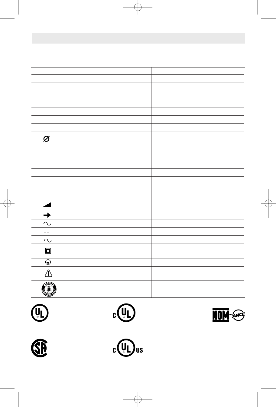
A
0
A
A
0
A
BM 1609929J64 12-05 12/12/05 4:07 PM Page 29
Símbolos
IMPORTANTE: Es posible que algunos de los símbolos siguientes se usen en su herramienta. Por favor,
estúdielos y aprenda su significado. La interpretación adecuada de estos símbolos le permitirá utilizar la
herramienta mejor y con más seguridad.
Símbolo Nombre Designación/explicación
V Volt Tensión (potencial)
A Ampere Corriente
Hz Hertz Frecuencia (ciclos por segundo)
W Watt Potencia
kg Kilogramo Peso
min Minuto Tiempo
s Segundo Tiempo
Diámetro Tamaño de las brocas taladradoras,
muelas, etc.
n
0
.../min Revoluciones o alternación por minuto Revoluciones, golpes, velocidad de
0 Posición "off" (apagado) Velocidad cero, par motor cero...
1, 2, 3, ... Graduaciones del selector Graduaciones de velocidad, par motor o
I, II, III, posición. Un número más alto significa
Velocidad sin carga Velocidad rotacional sin carga
superficie, órbitas, etc., por minuto
mayor velocidad
Selector infinitamente variable con La velocidad aumenta desde la
apagado graduación de 0
Flecha Acción en la dirección de la flecha
Corriente alterna Tipo o una característica de corriente
Corriente continua Tipo o una característica de corriente
Corriente alterna o continua Tipo o una característica de corriente
Construcción de clase II Designa las herramientas de construcción
con aislamiento doble.
Terminal de toma de tierra Terminal de conexión a tierra
Símbolo de advertencia Alerta al usuario sobre mensajes de `
advertencia
Sello RBRC de Ni-Cd Designa el programa de reciclaje de baterías
de Ni-Cd
Este símbolo indica que esta
herramienta está catalogada
por Underwriters
Laboratories.
Este símbolo indica que esta
herramienta está catalogada
por la Canadian Standards
Association.
Este símbolo indica que
Underwriters Laboratories ha
catalogado esta herramienta
indicando que cumple las
normas canadienses.
Este símbolo indica que esta
herramienta está catalogada por
Underwriters Laboratories y que
Underwriters Laboratories la ha
catalogado según las normas
canadienses.
Este símbolo
indica que esta
herramienta
cumple con la
norma mexicana
oficial (NOM).
-29-
Page 30

BM 1609929J64 12-05 12/12/05 4:07 PM Page 30
Descripción funcional y especificaciones
!
ADVERTENCIA
arrancar la herramienta accidentalmente.
BOTON DE SUELTA/AJUSTE
DEL PROTECTOR
Desconecte el enchufe de la fuente de energía antes de realizar cualquier ensamblaje o
ajuste, o cambiar accesorios. Estas medidas de seguridad preventivas reducen el riesgo de
CIERRE DEL
HUSILLO
Amoladoras angulares
FIG. 1
BOTON DEL
INTERRUPTOR
ABERTURA DE
VENTILACION
VELOCIDAD VARIABLE CON
AJUSTE DE DIAL (modelo
1803EVS solamente)
CONTROL DE LA
VIBRACIÓN
RUEDA DE
AMOLA
Modelo número 1800 1801 y 1803EVS 1806E
Máx. diámetro de muela 4 1/2" (115mm) 5" (125mm) 6" (150mm)
Rosca del husillo
Máx. rueda con rayos de alambre 4" de diám. 4" de diám. 4" de diám.
Máx. escobilla acopada de alambre 3" de diám. 3" de diám. 3" de diám.
Máx. disco de lijar
Máx. rueda de corte 4 1/2" de diám. 5" de diám. 6" de diám.
Máx. rueda de diamante de corte en seco
NOTA: Para obtener las especificaciones de la herramienta, consulte
PROTECTOR DE
LA MUELA
5/8"-11 GNU 5/8 "-11 GNU 5/8 "-11 GNU
4 1/2" de diám.
4 1/2" de diám.
la placa del fabricante colocada en la herramienta.
MANGO
LATERAL
5" de diám.
5" de diám.
6" de diám.
6" de diám.
-30-
Page 31
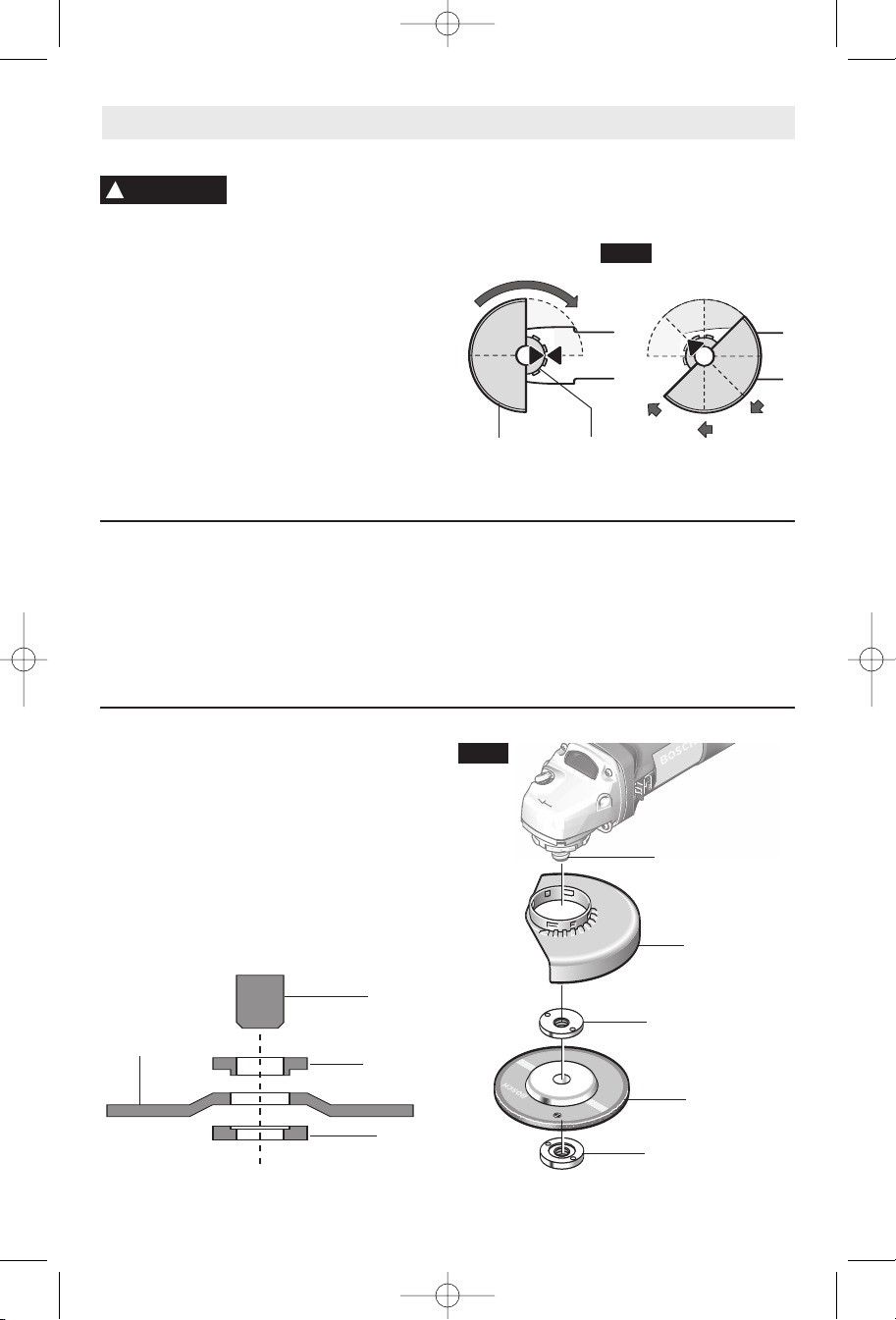
BM 1609929J64 12-05 12/12/05 4:07 PM Page 31
Ensamblaje
INSTALACION DEL PROTECTOR DE LA MUELA
!
ADVERTENCIA
El protector de la muela se debe
colocar cuando se utilizan ruedas
de amolar de disco. Mantenga siempre el protector de la
muela entre usted y la pieza de trabajo cuando esté
amolando. La posición del protector puede ajustarse
para acomodar la operación que se esté realizando.
Para colocar el protector de la muela, DESCONECTE la
herramienta de la fuente de energía. Posicione el
protector en el cuello del husillo de modo que la flecha
del protector quede alineada con la flecha del cuello del
husillo. Gire el protector de la muela 90° en el sentido
de las agujas del reloj hasta que se acople en su sitio
con un chasquido (Fig. 2).
PARA AJUSTAR EL PROTECTOR: Oprima el botón de
suelta del protector (Fig. 1), gire el protector hasta la
posición deseada, suelte el botón y deje que el protector
se acople en su sitio con un chasquido.
TUERCA DE FIJACION Y PESTAÑA DE SOPORTE
La herramienta está equipada con un husillo roscado
para montar accesorios. Utilice siempre la tuerca de
fijación suministrada (y la pestaña de soporte) que tiene
el mismo tamaño de rosca que el husillo.
PARA QUITAR EL PROTECTOR: Oprima el botón de
suelta del protector, gire el protector hasta que la flecha
del protector se alinee con la flecha del cuello del husillo
y quite el protector del cuello.
FIG. 2
PROTECTOR
DE LA
MUELA
CUELLO
DEL
HUSILLO
MANGO LATERAL
El mango lateral, utilizado para guiar y equilibrar la
herramienta, se puede enroscar en la parte delantera de
la caja del motor en cualquiera de los dos lados de la
herramienta, dependiendo de la preferencia personal y
de la comodidad. Utilice el mango lateral para un control
seguro y una utilización fácil.
Ensamblaje de la rueda de amolar de disco
(modelos 1800, 1801 y 1803EVS solamente)
Desconecte la herramienta de la fuente de energía.
Asegúrese de que el protector de la muela esté colocado
en su sitio para amolar. Coloque la PESTAÑA DE
SOPORTE y la RUEDA DE AMOLAR en el husillo.
Enrosque la tuerca de fijación y apriétela usando la llave
de tuercas de fijación suministrada, a la vez que sujeta
el cierre del husillo hacia adentro (Fig. 3).
PARA DESMONTAR: Invierta el procedimiento.
HUSILLO
RUEDA DE
AMOLAR DE
DISCO
PESTAÑA
DE SOPORTE
TUERCA
DE FIJACION
-31-
FIG. 3
HUSILLO
PROTECTOR DE
LA MUELA
PESTAÑA
DE SOPORTE
RUEDA DE
AMOLAR DE DISCO
TUERCA DE FIJACION
Page 32

BM 1609929J64 12-05 12/12/05 4:07 PM Page 32
Ensamblaje de la rueda de amolar de disco
Desconecte la herramienta de la fuente de energía.
Asegúrese de que el protector de la muela esté colocado
en su sitio para amolar.
Cuando utilice ruedas de amolar automontables,
enrósquelas directamente en el husillo.
Cuando utilice ruedas de montaje, enrosque la
PESTAÑA TRASERA en el husillo y luego coloque la
RUEDA DE AMOLAR en el husillo. Enrosque la tuerca de
fijación y apriete dicha tuerca utilizando una llave para
tuercas de fijación provista con el juego de adaptador, a
la vez que sujeta hacia adentro el cierre del husillo
(Fig. 4).
PARA QUITAR LA RUEDA DE AMOLAR: Invierta el
procedimiento.
(modelo 1806E solamente)
Ensamblaje de la rueda de corte de
mampostería
Para cortar materiales de mampostería tales como
ladrillo, loseta, piedra, etc, es mejor utilizar una rueda de
diamante de corte en seco. Utilice únicamente una
tuerca de fijación y una pestaña con diámetros iguales.
El protector de la rueda se debe utilizar con una rueda
de diamante de corte en seco.
!
ADVERTENCIA
herramienta para cortar.
Desconecte la herramienta de la fuente de energía.
Asegúrese de que el protector de la muela esté
colocado en su sitio para amolar. Coloque la PESTAÑA
DE SOPORTE y la RUEDA DE DIAMANTE DE CORTE EN
SECO en el husillo. Enrosque la tuerca de fijación y
apriétela usando la llave de tuercas de fijación
suministrada, a la vez que sujeta el cierre del husillo
hacia adentro (Fig. 5).
RUEDA DE
DIAMANTE DE
CORTE EN SECO
No utilice agua ni ningún otro
líquido de enfriamiento con esta
HUSILLO
PESTAÑA
DE SOPORTE
TUERCA
DE FIJACION
FIG. 4
H
USILLO
PROTECTOR DE
LA MUELA
PESTAÑA
DE SOPORTE
RUEDA DE
AMOLAR DE DISCO
TUERCA DE FIJACION
PARA DESMONTAR: Invierta el procedimiento.
FIG. 5
HUSILLO
PROTECTOR DE
LA MUELA
PESTAÑA DE
SOPORTE
RUEDA DE
DIAMANTE DE
CORTE EN SECO
TUERCA DE FIJACION
Al cortar, realice únicamente pequeñas pasadas por la
pieza de trabajo cada vez. Tenga en cuenta que se
puede producir retroceso en cualquier momento.
Mantenga las dos manos sobre las herramientas para
un control máximo.
-32-
Page 33

BM 1609929J64 12-05 12/12/05 4:07 PM Page 33
Ensamblaje de los accesorios de lijar
ZAPATA DE SOPORTE
!
ADVERTENCIA
velocidad máxima de funcionamiento con seguridad no
es superada por la velocidad indicada en la placa del
fabricante de la herramienta.
!
ADVERTENCIA
las operaciones de lijado. Reinstale siempre el protector
de la muela cuando realice la conversión a operaciones
de amolado.
PARA INSTALAR LA ZAPATA DE SOPORTE Y
Desconecte la herramienta de la fuente de energía.
Apoye la herramienta sobre su lado superior (husillo
hacia arriba). Coloque la zapata de soporte de caucho
sobre el eje del husillo. Centre el disco de lijar sobre la
zapata de soporte. Introduzca la tuerca de fijación a
través del disco y enrósquela en el husillo hasta donde
pueda con los dedos. Ensamblaje de los accesorios de
lijar (Fig. 6).
PARA QUITAR LA ZAPATA DE SOPORTE
Desconecte la herramienta de la fuente de energía.
Utilizando la llave de tuercas de fijación, desenrosque la
tuerca del husillo mientras sujeta el husillo hacia
adentro.
ENSAMBLAJE DEL CEPILLO DE ALAMBRE
Antes de colocar la escobilla de alambre en esta
herramienta, desconéctela de la fuente de energía. Las
Antes de colocar una zapata de
soporte, asegúrese de que su
El protector de la muela no se
puede utilizar para la mayoría de
EL DISCO DE LIJAR
Y EL DISCO DE LIJAR
escobillas de alambre están equipadas con su
propio cubo roscado; simplemente enrósquelas en el
husillo. Asegúrese de que quedan asentadas contra el
hombro antes de encender la herramienta (posición
“ON”).
FIG. 6
HUSILLO
ZAPATA DE
SOPORTE
DISCO DE
LIJAR
TUERCA
DE FIJACION
CEPILLO
DE ALAMBRE
Instrucciones de funcionamiento
INTERRUPTOR CORREDIZO “ON/OFF”
(DE ENCENDIDO Y APAGADO) CON CIERRE
La herramienta se enciende con el botón del interruptor
ubicado en un lado de la caja del motor. El interruptor
se puede fijar en la posición "ON" (encendido), lo cual
resulta práctico al realizar operaciones prolongadas de
amolado.
Para encender la herramienta (posicion “ON”) sin
dejarla fija, deslice el botón de interruptor hacia adelante
ejerciendo presión UNICAMENTE sobre la parte de
ATRAS del botón. Al soltar completamente el botón del
interruptor, éste volverá a la posición “OFF”.
PARA FIJAR EL INTERRUPTOR EN LA POSICION “ON”,
deslice el botón del interruptor hacia adelante y
OPRIMA la parte DELANTERA.
PARA DESBLOQUEAR EL INTERRUPTOR, simplemente
oprima y suelte la parte de ATRAS del botón. El
interruptor está accionado por resorte y saltará de
vuelta automáticamente.
!
ADVERTENCIA
herramienta, ya que el par de fuerzas del motor puede
hacer que la herramienta se tuerza.
Arranque la herramienta antes de aplicarla a la pieza de
trabajo. Levante la herramienta de la pieza de trabajo
antes de soltar el interruptor. NO encienda y apague el
interruptor mientras la herramienta está sometida a
carga; esto acortará enormemente la vida del
interruptor.
Agarre la herramienta con las dos
manos cuando arranque la
-33-
Page 34

BM 1609929J64 12-05 12/12/05 4:07 PM Page 34
CIRCUITOS ELECTRONICOS DE RETROALIMENTACION
(CER) (modelos 1803EVS y 1806E solamente)
El sistema electrónico interno de retroalimentación
proporciona un “arranque suave” que reducirá las
tensiones que se producen como consecuencia de un
arranque de par motor alto. El sistema también ayuda a
mantener la velocidad de percusión y la velocidad de
rotación prácticamente constantes entre la situación sin
carga y la situación con carga.
TOPE ANTIRRETROCESO
La herramienta está equipada con un dispositivo de
tope antirretroceso. Este dispositivo apaga
automáticamente la herramienta si ésta pierde
velocidad o si la rueda encuentra una fuerza excesiva.
Para reanudar la operación, PONGA EL
INTERRUPTOR DE ENCENDIDO Y APAGADO EN LA
POSICIÓN DE APAGADO Y LUEGO REARRANQUE LA
HERRAMIENTA.
PROTECCIÓN CONTRA REARRANQUES
El dispositivo de protección contra rearranques fue
diseñado para ayudar a impedir los arranques
accidentales después de que se haya interrumpido la
alimentación eléctrica. Para reanudar la operación si
esto ocurre, PONGA EL INTERRUPTOR DE
ENCENDIDO Y APAGADO EN LA POSICIÓN DE
APAGADO Y LUEGO REARRANQUE LA
HERRAMIENTA.
PROTECCION CONTRA SOBRECARGA
(modelos 1803EVS y 1806E solamente)
La herramienta está equipada con protección contra
sobrecarga para proteger el motor. Si la herramienta se
detiene durante el funcionamiento, APAGUE EL
INTERRUPTOR INMEDIATAMENTE y deje que el motor
se enfríe durante unos 30 segundos haciendo que
funcione sin carga. Si la protección contra sobrecarga
detiene repetidamente la herramienta, la fuerza excesiva
está haciendo que la herramienta se sobrecargue. No
presione con tanta fuerza y deje que la herramienta haga
el trabajo.
ELOCIDAD VARIABLE CON AJUSTE DE DIAL
V
(modelo 1803EVS solamente)
La herramienta también está equipada con undial de
velocidad variable. Las RPM de la amoladora se pueden
prefijar desde cero hasta las RPM máximas indicadas
en la placa del fabricante girando el dial que está en la
caja del motor. Si la herramienta está en marcha a una
velocidad fija durante períodos de tiempo prolongados,
puede que sea necesario hacer funcionar la herramienta
a toda velocidad sin carga para enfriar el motor.
Posición del Aplicación-
dial RPM Material Accesorio
aprox.
(2800) disco de bruñir
(5300-7500) maciza y pintura
(7500) Remoción de Disco de lijar
(8800-11000) piedra
Pulido de plástico Bonete de lana
de cordero, disco de
1 pulir de fieltro o
Amolado de precisión Disco de amolar
de herramientas de
metal
2-3 Remoción de madera Disco de lijar
peinture
Cepillado de madera Cepillo acopado
3
herrumbre en metal
4-6 Amolado de metal o Disco de amolar
Desbastado de metal Disco de debastar
6
(11000) Corte de piedra
Disco de corte
Operación de amolado
SELECCION DE RUEDAS DE AMOLAR
!
ADVERTENCIA
velocidad máxima de funcionamiento con seguridad no
es superada por la velocidad indicada en la placa del
fabricante de la amoladora. No exceda el diámetro de
muela recomendado.
RUEDAS DE AMOLAR DE DISCO
Las ruedas de amolar se deben seleccionar
cuidadosamente para utilizar la amoladora con una
eficiencia máxima. Las muelas varían en cuanto a tipo
de abrasivo, adhesivo, dureza, tamaño del grano y
estructura. El tipo correcto de muela a utilizar está
determinado por el trabajo.
El amolado eficiente se logra controlando la presión y
manteniendo un ángulo de 10˚ a 15˚ entre la muela y la
Antes de utilizar una rueda de
amolar, asegúrese de que su
CONSEJOS PARA AMOLAR
pieza de trabajo. Si la muela está en posición horizontal,
es difícil controlar la herramienta. Si el ángulo es
demasiado pronunciado, la presión se concentra en un
área pequeña, haciendo que la superficie de trabajo se
queme.
!
ADVERTENCIA
Una presión excesiva o repentina
sobre la muela retrasará la acción
de amolado y someterá a la muela a un esfuerzo
peligroso.
Al amolar con una muela nueva, asegúrese de amolar
mientras que tira de la herramienta hacia atrás hasta
que el borde de la muela quede redondeado. Las muelas
nuevas tienen esquinas afiladas que tienden a “morder”
o cortar la pieza de trabajo al empujar hacia adelante.
-34-
Page 35

BM 1609929J64 12-05 12/12/05 4:07 PM Page 35
Operaciones de lijado
Los discos de lijar están hechos de granos de óxido de
SELECCION DEL DISCO DE LIJAR
aluminio extremadamente duros y afilados, adheridos
con resinas fenólicas a un fuerte soporte de fibra para
servicios pesados rápidos y larga duración. El disco
varía en cuanto a tamaño y separación de los granos
abrasivos. CAPA ABIERTA (tipo H) - utilizado para
materiales blandos y sobre pintura o barniz. CAPA
CERRADA (tipo K) - utilizado para metal, madera dura,
piedra, mármol y otros materiales donde las partículas
amoladas son finas.
Los discos de lijar varían en grano desde 16 (muy
grueso) hasta 180 (muy fino). Para obtener mejores
resultados, seleccione los discos de lijar
cuidadosamente. Muchos trabajos requieren la
utilización de varios tamaños de grano y a veces se
CONSEJOS PARA LIJAR
Para mejores resultados, incline la lijadora de disco
hasta un ángulo de 10˚ a 15° mientras lija para que
aproximadamente sólo 1 pulgada de la superficie
alrededor del borde del disco esté en contacto con la
superficie de trabajo.
!
ADVERTENCIA
Si el disco (accesorio) se
mantiene en posición horizontal o
si el borde de atrás del disco entra en contacto con la
pieza de trabajo, se puede producir un violento impulso
hacia un lado.
Si la lijadora se inclina demasiado, la acción de lijado
será demasiado grande y se producirá una superficie
cortada bastamente o acanalado y atasco.
Guíe la lijadora de disco con pasadas transversales.
Tenga cuidado de no mantener la lijadora en el mismo
sitio demasiado tiempo. No utilice un movimiento
circular, ya que esto causa marcas de remolino. Antes
de la utilización, haga una prueba sobre material de
desecho.
No fuerce ni aplique presión al lijar. Utilice únicamente el
peso de la herramienta como presión. Un exceso de
presión en realidad entorpece el funcionamiento de la
herramienta. Si se desea una remoción de material más
rápida, cambie a un disco de grano más grueso.
requieren tanto discos de “capa abierta” como de “capa
cerrada” para realizar el trabajo más deprisa. Consulte el
cuadro para ver ejemplos de aplicaciones.
OPERACION: Reacabado de superficies de madera o de metal pintadas.
OBSERVACIONES GRANO
ara quitar pintura y alisar Grueso
P
irregularidades de la superficie. 16-24-30
ara alisar Mediano
P
el lijado basto. 36-50-80
Para quitar arañazos dejados por discos F
anteriores 100-120
Para alisar superficies para pintar, Muy fino
pulir o encerar. 150-180
ino
Quite la pintura gomosa del metal con un disco de “capa
abierta”. Lije hasta que empiecen a saltar chispas y
entonces pare y cambie a un disco de “capa cerrada”
para quitar la pintura que quede.
LIJADO DE MADERA
Al lijar madera, el sentido del movimiento del disco en el
punto de contacto debe ser tan paralelo a la veta como
sea posible. El corte rápido de los discos y la
configuración de arañazos tipo remolino que crean de
vez en cuando prohíben generalmente su utilización para
producir el acabado final.
Los arañazos y las marcas circulares suelen producirse
como resultado de la utilización de un grano demasiado
grueso. Cuando cambie a un grano más fino, lije
cruzando las líneas de lijado que fueron hechas por un
disco más grueso utilizado anteriormente.
LIJADO DE METAL
Al lijar automóviles o electrodomésticos, limpie el metal
con un disolvente ininflamable o con un limpiador
comercial para quitar toda la cera y la grasa. Al hacer
esto primero, los discos de lijar lijarán mejor y durarán
más.
Para trabajo pesado, utilice primero un disco de grano
grueso. Siga con un grano mediano para quitar los
arañazos. Para producir un acabado liso, utilice un disco
de grano fino.
-35-
Page 36
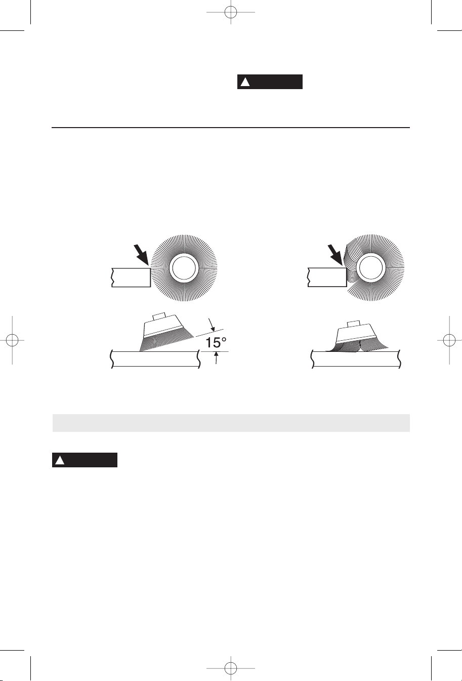
BM 1609929J64 12-05 12/12/05 4:07 PM Page 36
Operaciones con escobillas de alambre
Las escobillas de alambre están diseñadas para “limpiar”
acero estructural, piezas fundidas, chapa metálica,
piedra y hormigón. Se utilizan para quitar herrumbre,
costra y pintura.
!
ADVERTENCIA
especialmente al trabajar en esquinas, bordes
afilados, etc. Eso puede causar pérdida de control y
retroceso.
Evite que el cepillo de alambre
rebote y se atasque,
1. Recuerde que las puntas de un cepillo de alambre
PRESIÓN DE CEPILLADO
hacen el trabajo. Utilice el cepillo con la presión más
ligera para que solamente las puntas del alambre
entren en contacto con la pieza de trabajo.
2. Si se utilizan presiones más grandes, se someterá a
los alambres a una tensión excesiva, lo cual dará
como resultado una acción de barrido, y si se
CORRECTO:
Las puntas de
alambre hacen el
trabajo.
Mantenimiento
continúa haciendo esto, podrá acortarse la duración
del cepillo debido a la fatiga del alambre.
3. Aplique el cepillo a la pieza de trabajo de manera
que tanta cara del cepillo como sea posible esté en
contacto completo con la pieza de trabajo. La
aplicación del lado o del borde del cepillo a la pieza de
trabajo causará la rotura del alambre y acortará la
duración del cepillo.
INCORRECTO:
Una presión
excesiva puede
causar la rotura
del alambre.
Servicio
!
ADVERTENCIA
autorizado pude dar lugar a la colocación incorrecta
de cables y componentes internos que podría
constituir un peligro serio. Recomendamos que todo el
servicio de las herramientas sea realizado por un Centro
de servicio de fábrica Bosch o por una Estación de
servicio Bosch autorizada.
LUBRICACIÓN DE LAS HERRAMIENTAS
Su herramienta Bosch ha sido lubricada adecuadamente
y está lista para la utilización. Se recomienda que las
herramientas con engranajes se vuelvan a engrasar con
un lubricante especial para engranajes en cada cambio
de escobillas.
El mantenimiento preventivo
realizado por personal no
Las escobillas y el conmutador de la herramienta han
ESCOBILLAS DE CARBÓN
sido diseñados para muchas horas de servicio fiable.
Para mantener un rendimiento óptimo del motor,
recomendamos que cada dos a seis meses se examinen
las escobillas. Sólo se deben usar escobillas de repuesto
Bosch genuinas diseñadas específicamente para su
herramienta.
RODAMIENTOS
Después de 300-400 horas de funcionamiento, o
después de cada segundo cambio de escobillas, los
rodamientos deben cambiarse en un Centro de servicio
de fábrica Bosch o en una Estación de servicio Bosch
autorizada. Los rodamientos que se vuelven ruidosos
(debido a la pesada carga o al corte de materiales muy
abrasivos) deben ser sustituidos inmediatamente para
evitar el sobrecalentamiento o el fallo del motor.
-36-
Page 37
BM 1609929J64 12-05 12/12/05 4:07 PM Page 37
Limpieza
!
ADVERTENCIA
mienta de la fuente de energía antes de la limpieza o
de la realización de cualquier mantenimiento. La
herramienta se puede limpiar más eficazmente con aire
comprimido seco. Use gafas de seguridad siempre que
limpie herramientas con aire comprimido.
Para evitar accidentes
desconecte siempre la herra-
Cordones de extensión
!
ADVERTENCIA
cordón con conductores de tamaño adecuado que sea
capaz de transportar la corriente necesaria para la
herramienta. Esto evitará caídas de tensión excesivas,
pérdida de potencia o recalentamiento. Las herramientas
conectadas a tierra deben usar cordones de extensión
de 3 hilos que tengan enchufes de 3 terminales y
receptáculos para 3 terminales.
NOTA: Cuanto más pequeño es el número de calibre,
más grueso es el cordón.
Si es necesario un cordón de
extensión, se debe usar un
Las aberturas de ventilación y las palancas de interruptor
deben mantenerse limpias y libres de materias extrañas.
No intente limpiar introduciendo objetos puntiagudos a
través de las aberturas.
!
PRECAUCION
Ciertos agentes de limpieza y
disolventes dañan las piezas de
plástico. Algunos de estos son: gasolina, tetracloruro de
carbono, disolventes de limpieza clorados, amoníaco y
detergentes domésticos que contienen amoníaco.
AMAÑOS RECOMENDADOS DE CORDONES DE EXTENSION
T
HERRAMIENTAS DE 120 V CORRIENTE ALTERNA
T
Capacidad
nominal en
amperes de la
herramienta
3-6
6-8
8-10
10-12
12-16
amaño del cordón en A.W.G.
Longitud del cordón en pies Longitud del cordón en metros
25 50 100 150 15 30 60 120
18 16 16 14 0,75 0,75 1,5 2,5
18 16 14 12 0,75 1,0 2,5 4,0
18 16 14 12 0,75 1,0 2,5 4,0
16 16 14 12 1,0 2,5 4,0 —
14 12 — — — — — —
Tamaños del cable en mm
2
Accesorios
* Protector de la muela * Tuerca de fijación
* Rueda de amolar * Pestaña de soporte
* Mango lateral * Llave de tuercas de fijación
(*= equipo estándar)
(**= accesorios opcionales)
-37-
Page 38

BM 1609929J64 12-05 12/12/05 4:07 PM Page 38
Robert Bosch Tool Corporation (“Seller”) warrants to the original purchaser only, that all BOSCH portable and benchtop power tools will be free from
defects in material or workmanship for a period of one year from date of purchase. SELLER’S SOLE OBLIGATION AND YOUR EXCLUSIVE REMEDY
under this Limited Warranty and, to the extent permitted by law, any warranty or condition implied by law, shall be the repair or replacement of parts,
without charge, which are defective in material or workmanship and which have not been misused, carelessly handled, or misrepaired by persons
other than Seller or Authorized Service Station. To make a claim under this Limited Warranty, you must return the complete portable or benchtop
power tool product, transportation prepaid, to any BOSCH Factory Service Center or Authorized Service Station. For Authorized BOSCH Power Tool
Service Stations, please refer to your phone directory.
THIS LIMITED WARRANTY DOES NOT APPLY TO ACCESSORY ITEMS SUCH AS CIRCULAR SAW BLADES, DRILL BITS, ROUTER BITS, JIGSAW
BLADES, SANDING BELTS, GRINDING WHEELS AND OTHER RELATED ITEMS.
ANY IMPLIED WARRANTIES SHALL BE LIMITED IN DURATION TO ONE YEAR FROM DATE OF PURCHASE. SOME STATES IN THE U.S., SOME
CANADIAN PROVINCES DO NOT ALLOW LIMITATIONS ON HOW LONG AN IMPLIED WARRANTY LASTS, SO THE ABOVE LIMITATION MAY NOT
APPLY TO YOU.
IN NO EVENT SHALL SELLER BE LIABLE FOR ANY INCIDENTAL OR CONSEQUENTIAL DAMAGES (INCLUDING BUT NOT LIMITED TO LIABILITY
FOR LOSS OF PROFITS) ARISING FROM THE SALE OR USE OF THIS PRODUCT. SOME STATES IN THE U.S. AND SOME CANADIAN PROVINCES
DO NOT ALLOW THE EXCLUSION OR LIMITATION OF INCIDENTAL OR CONSEQUENTIAL DAMAGES, SO THE ABOVE LIMIT ATION OR
EXCLUSION MAY NOT APPLY TO YOU.
THIS LIMITED WARRANTY GIVES YOU SPECIFIC LEGAL RIGHTS, AND YOU MAY ALSO HAVE OTHER RIGHTS WHICH VARY FROM STATE TO
STATE IN THE U.S., PROVINCE TO PROVINCE IN CANADA AND FROM COUNTRY TO COUNTRY.
THIS LIMITED WARRANTY APPLIES ONLY TO PORTABLE AND BENCHTOP ELECTRIC TOOLS SOLD WITHIN THE UNITED STATES OF AMERICA,
CANADA AND THE COMMONWEALTH OF PUERTO RICO. FOR WARRANTY COVERAGE WITHIN OTHER COUNTRIES, CONTACT YOUR LOCAL
BOSCH DEALER OR IMPORTER.
Robert Bosch Tool Corporation (le « vendeur ») garantit à l'acheteur initial seulement que tous les outils électriques portatifs et d'établi BOSCH
seront exempts de vices de matériaux ou d'exécution pendant une période d'un an depuis la date d'achat. LA SEULE OBLIGATION DU VENDEUR ET
LE SEUL RECOURS DE L’ACHETEUR sous la présente garantie limitée, et en autant que la loi le permette sous toute garantie ou condition implicite
qui en découlerait, sera l’obligation de remplacer ou réparer gratuitement les pièces défectueuses matériellement ou comme fabrication, pourvu que
lesdites défectuosités ne soient pas attribuables à un usage abusif ou à quelque réparation bricolée par quelqu’un d’autre que le vendeur ou le
p
ersonnel d’une station-service agréée.
portatif ou d'établi complet, port payé, à tout centre de service agréé ou centre de service usine. Veuillez consulter votre annuaire téléphonique
pour les adresses.
LA PRÉSENTE GARANTIE NE S’APPLIQUE PAS AUX ACCESSOIRES TELS QUE LAMES DE SCIES CIRCULAIRES, MÈCHES DE PERCEUSES, FERS
DE TOUPIES, LAMES DE SCIES SAUTEUSES, COURROIES DE PONÇAGE, MEULES ET AUTRES ARTICLES DU GENRE.
TOUTE GARANTIE IMPLICITE SERA LIMITÉE COMME DURÉE À UN AN À COMPTER DE LA DATE D’ACHAT. CERTAINS ÉTATS AMÉRICAINS,
CERTAINES PROVINCES CANADIENNES N’ADMETTANT PAS LE PRINCIPE DE LA LIMITATION DE LA DURÉE DES GARANTIES IMPLICITES, IL
EST POSSIBLE QUE LES LIMITATIONS CI-DESSUS NE S’APPLIQUENT PAS À VOTRE CAS.
EN AUCUN CAS LE VENDEUR NE SAURAIT ÊTRE TENU POUR RESPONSABLE DES INCIDENTS OU DOMMAGES INDIRECTS (INCLUANT, MAIS NE
SE LIMITANT PAS AUX PERTES DE PROFITS) CONSÉCUTIFS À LA VENTE OU L’USAGE DE CE PRODUIT. CERTAINS ÉTATS AMÉRICAINS ET
CERTAINES PROVINCES CANADIENNES N’ADMETTANT PAS LE PRINCIPE DE LA LIMITATION NI L’EXCLUSION DES DOMMAGES INDIRECTS ET
CONSÉQUENTIELS, IL EST POSSIBLE QUE LES LIMITATIONS OU EXCLUSIONS CI-DESSUS NE S’APPLIQUENT PAS À VOTRE CAS.
LA PRÉSENTE GARANTIE VOUS ACCORDE DES DROITS BIEN DÉTERMINÉS, Y COMPRIS POSSIBLEMENT CERTAINS DROITS VARIABLES DANS
LES DIFFÉRENTS ÉTATS AMÉRICAINS, PROVINCES CANADIENNE ET DE PAYS À PAYS.
CETTE GARANTIE LIMITÉE NE S'APPLIQUE QU'AUX OUTILS ÉLECTRIQUES PORTATIFS ET D'ÉTABLI VENDUS AUX ÉTATS-UNIS D'AMÉRIQUE,
AU CANADA ET AU COMMONWEALTH DE PORTO RICO. POUR COUVERTURE DE GARANTIE DANS LES AUTRES PAYS, CONTACTEZ VOTRE
IMPORTATEUR OU REVENDEUR BOSCH LOCAL.
GARANTIA LIMITADA PARA HERRAMIENTAS MECANICAS PORTATILES Y PARA TABLERO DE BANCO BOSCH
Robert Bosch Tool Corporation ("el Vendedor") garantiza, únicamente al comprador original, que todas las herramientas mecánicas portátiles y
para tablero de banco BOSCH estarán libres de defectos de material o de fabricación durante un período de un año a partir de la fecha de compra.
LA UNICA OBLIGACION DEL VENDEDOR Y EL RECURSO EXCLUSIVO QUE USTED TIENE bajo esta Garantía Limitada y, hasta donde la ley lo
permita, bajo cualquier garantía o condición implícita por ley, consistirá en la reparación o sustitución sin costo de las piezas que presenten
defectos de material o de fabricación y que no hayan sido utilizadas incorrectamente, manejadas descuidadamente o reparadas incorrectamente
por personas que no sean el Vendedor o una Estación de servicio autorizada. Para efectuar una reclamación bajo esta Garantía Limitada, usted
debe devolver el producto, que consiste en la herramienta mecánica portátil o para tablero de banco completa, con el transporte pagado, a
cualquier Centro de servicio de fábrica o Estación de servicio autorizada. Para Estaciones de servicio autorizadas de herramientas mecánicas
BOSCH, por favor, consulte el directorio telefónico.
ESTA GARANTIA LIMITADA NO SE APLICA A ARTICULOS ACCESORIOS TALES COMO HOJAS PARA SIERRAS CIRCULARES, BROCAS PARA
TALADROS, BROCAS PARA FRESADORAS, HOJAS PARA SIERRAS DE VAIVEN, CORREAS PARA LIJAR, RUEDAS DE AMOLAR Y OTROS
ARTICULOS RELACIONADOS.
TODAS LAS GARANTIAS IMPLICITAS TENDRAN UNA DURACION LIMITADA A UN AÑO A PARTIR DE LA FECHA DE COMPRA. ALGUNOS
ESTADOS DE LOS EE.UU. Y ALGUNAS PROVINCIAS CANADIENSES NO PERMITEN LIMITACIONES EN CUANTO A LA DURACION DE UNA
GARANTIA IMPLICITA, POR LO QUE ES POSIBLE QUE LA LIMITACION ANTERIOR NO SEA APLICABLE EN EL CASO DE USTED.
EL VENDEDOR NO SERA RESPONSABLE EN NINGUN CASO DE NINGUN DAÑO INCIDENTAL O EMERGENTE (INCLUYENDO PERO NO LIMITADO
A RESPONSABILIDAD POR PERDIDA DE BENEFICIOS) QUE SE PRODUZCA COMO CONSECUENCIA DE LA VENTA O UTILIZACION DE ESTE
PRODUCTO. ALGUNOS ESTADOS DE LOS EE.UU. Y ALGUNAS PROVINCIAS CANADIENSES NO PERMITEN LA EXCLUSION O LIMITACION DE
LOS DAÑOS INCIDENTALES O EMERGENTES, POR LO QUE ES POSIBLE QUE LA LIMITACION O EXCLUSION ANTERIOR NO SEA APLICABLE EN
EL CASO DE USTED.
ESTA GARANTIA LIMITADA LE CONFIERE A USTED DERECHOS LEGALES ESPECIFICOS Y ES POSIBLE QUE USTED TAMBIEN TENGA OTROS
DERECHOS QUE VARIAN DE ESTADO A ESTADO EN LOS EE.UU., DE PROVINCIA A PROVINCIA EN CANADA Y
ESTA GARANTIA LIMITADA SE APLICA SOLAMENTE A HERRAMIENTAS ELECTRICAS PORTATILES Y PARA TABLERO DE BANCO VENDIDAS EN
LOS ESTADOS UNIDOS DE AMERICA, CANADA Y EL ESTADO LIBRE ASOCIADO DE PUERTO RICO. PARA COBERTURA DE GARANTIA EN OTROS
PAISES, PONGASE EN CONTACTO CON SU DISTRIBUIDOR O IMPORTADOR LOCAL DE BOSCH.
LIMITED WARRANTY OF BOSCH PORTABLE AND BENCHTOP POWER TOOLS
ARANTIE LIMITÉE DES OUTILS ÉLECTRIQUES PORTATIFS ET D'ÉTABLI BOSCH
G
Pour présenter une réclamation en vertu de cette garantie limitée, vous devez renvoyer l'outil électrique
DE UN PAIS A OTRO
.
© Robert Bosch Tool Corporation 1800 W. Central Road Mt. Prospect, IL 60056-2230
Exportado por: Robert Bosch Tool Corporation Mt. Prospect, IL 60056 -2230, E.U.A.
Importado en México por: Robert Bosch, S.A. de C.V., Calle Robert Bosch No. 405, Zona Industrial,
Toluca, Edo. de México, C.P. 50070, Tel. (722) 2792300
1 609 929 J64 12/05
Printed in Germany
 Loading...