

Operating/Safety Instructions
Consignes de fonctionnement/sécurité
Instrucciones de funcionamiento
y seguridad
IMPORTANT: IMPORTANT : IMPORTANTE:
Read Before Using Lire avant usage Leer antes de usar
For English Parlez-vous français? ¿Habla español?
See page 2 Voir page 12 Ver página 22
Consumer Information
Renseignement des consommateurs
Información para el consumidor
Toll Free Number: Appel gratuit : Número de teléfono gratuito:
1-877-BOSCH99 (1-877-267-2499) http://www.boschtools.com
1775E
BM 3609929818 3/03 3/10/03 8:42 AM Page 1

Read and understand all instructions. Failure to follow all instructions
listed below, may result in electric shock, fire and/or serious personal injury.
SAVE THESE INSTRUCTIONS
-2-
Work Area
Keep your work area clean and well lit.
Cluttered benches and dark areas invite
accidents.
Do not operate power tools in explosive
atmospheres, such as in the presence of
flammable liquids, gases, or dust. Power
tools create sparks which may ignite the
dust or fumes.
Keep by-standers, children, and visitors
away while operating a power tool.
Distractions can cause you to lose control.
Electrical Safety
Double Insulated tools are equipped with
a polarized plug (one blade is wider than
the other.) This plug will fit in a polarized
outlet only one way. If the plug does not
fit fully in the outlet, reverse the plug. If it
still does not fit, contact a qualified
electrician to install a polarized outlet. Do
not change the plug in any way. Double
Insulation eliminates the need for the
three wire grounded power cord and
grounded power supply system. Before
plugging in the tool, be certain the outlet
voltage supplied is within the voltage marked
on the nameplate. Do not use “AC only”
rated tools with a DC power supply.
Avoid body contact with grounded
surfaces such as pipes, radiators, ranges
and refrigerators. There is an increased
risk of electric shock if your body is
grounded. If operating the power tool in
damp locations is unavoidable, a Ground
Fault Circuit Interrupter must be used to
supply the power to your tool. Electrician’s
rubber gloves and footwear will further
enhance your personal safety.
Don't expose power tools to rain or wet
conditions. Water entering a power tool will
increase the risk of electric shock.
Do not abuse the cord. Never use the
cord to carry the tools or pull the plug
from an outlet. Keep cord away from
heat, oil, sharp edges or moving parts.
Replace damaged cords immediately.
Damaged cords increase the risk of electric
shock.
When operating a power tool outside, use
an outdoor extension cord marked "W-A"
or "W." These cords are rated for outdoor
use and reduce the risk of electric shock.
Refer to “Recommended sizes of Extension
Cords” in the Accessory section of this
manual.
Personal Safety
Stay alert, watch what you are doing and
use common sense when operating a
power tool. Do not use tool while tired or
under the influence of drugs, alcohol, or
medication. A moment of inattention while
operating power tools may result in serious
personal injury.
Dress properly. Do not wear loose
clothing or jewelry. Contain long hair.
Keep your hair, clothing, and gloves away
from moving parts. Loose clothes, jewelry,
or long hair can be caught in moving parts.
Keep handles dry, clean and free from oil
and grease.
Avoid accidental starting. Be sure switch
is “OFF” before plugging in. Carrying tools
with your finger on the switch or plugging in
tools that have the switch “ON” invites
accidents.
Remove adjusting keys or wrenches
before turning the tool “ON”. A wrench or
a key that is left attached to a rotating part
of the tool may result in personal injury.
Do not overreach. Keep proper footing
and balance at all times. Proper footing
and balance enables better control of the
tool in unexpected situations.
Use safety equipment. Always wear eye
protection. Dust mask, non-skid safety
shoes, hard hat, or hearing protection must
be used for appropriate conditions.
!
WARNING
Power Tool Safety Rules
BM 3609929818 3/03 3/10/03 8:42 AM Page 2

-3-
Tuckpointer Safety Rules
Tool Use and Care
Use clamps or other practical way to
secure and support the workpiece to a
stable platform. Holding the work by hand
or against your body is unstable and may
lead to loss of control.
Do not force tool. Use the correct tool for
your application. The correct tool will do
the job better and safer at the rate for which
it is designed.
Do not use tool if switch does not turn it
“ON” or “OFF”. Any tool that cannot be
controlled with the switch is dangerous and
must be repaired.
Disconnect the plug from the power
source before making any adjustments,
changing accessories, or storing the tool.
Such preventive safety measures reduce the
risk of starting the tool accidentally. Store
idle tools out of reach of children and
other untrained persons. Tools are
dangerous in the hands of untrained users.
Maintain tools with care. Keep cutting
tools sharp and clean. Properly maintained
tools, with sharp cutting edges are less likely
to bind and are easier to control. Any
alteration or modification is a misuse and
may result in a dangerous condition.
Check for misalignment or binding of
moving parts, breakage of parts, and any
other condition that may affect the tools
operation. If damaged, have the tool
serviced before using. Many accidents are
caused by poorly maintained tools. Develop
a periodic maintenance schedule for your
tool.
Use only accessories that are
recommended by the manufacturer for
your model. Accessories that may be
suitable for one tool,
may become hazardous
when used on another tool.
Service
Tool service must be performed only by
qualified repair personnel. Service or
maintenance performed by unqualified
personnel could result in a risk of injury. For
example: internal wires may be misplaced or
pinched, safety guard return springs may be
improperly mounted.
When servicing a tool, use only identical
replacement parts. Follow instructions in
the Maintenance section of this manual.
Use of unauthorized parts or failure to follow
Maintenance Instructions may create a risk
of electric shock or injury. Certain cleaning
agents such as gasoline, carbon
tetrachloride, ammonia, etc. may damage
plastic parts.
This machine is intended primarily for
tuckpointing applications and some small
abrasive masonry cut off applications. It
is not intended for metal or wood cutting.
Always use wheel guard system and
auxiliary handle with this tool. The guard
must always be securely attached to the
tool and positioned for maximum safety,
so the least amount of wheel is exposed
on the operators’ side of the tool. A guard
protects operator from broken wheel
fragments and swarf from grinding. The
auxiliary handle provides additional stability
and control in tuckpointing and cut off
applications.
Hold tool by insulated gripping surfaces
when performing an operation where the
abrasive wheels may contact hidden
wiring or its own cord. Contact with a
“live” wire will make exposed metal parts of
the tool “live” and shock the operator.
Always use auxiliary handle for maximum
control over torque reaction or kick-back.
Operation of the tuckpointer without the side
handle could cause loss of control of the
tuckpointer, resulting in possible serious
personal injury.
Wear proper apparel while using an
abrasive tool. Use thick cushioned
gloves and wear ear protectors when
using the tool and limit exposure time by
taking frequent rest periods. Face shield
or at least safety goggles, dust mask,
leather gloves and shop apron capable of
stopping small wheel or workpiece
fragments. Prolonged exposure to high
BM 3609929818 3/03 3/10/03 8:42 AM Page 3

intensity noise can cause hearing loss.
Vibration caused by grinding action may be
harmful to your hands and arms.
Use only Type 1 abrasive wheels with the
correct rated diameter and arbor hole.
Never use damaged or incorrect wheel
flanges or round nut. Other types of
wheels are not intended to apply load on
periphery and may shatter. Wheels with
arbor holes that do not match the mounting
hardware of the tool will run eccentrically,
vibrate excessively and will cause loss of
control.
Do not use a wheel that is larger than the
maximum recommended size for your
tool, or worn down damaged wheels from
larger abrasive cut off machines. Wheels
intended for larger tools are not suitable for
the higher speed of a smaller tool, these
wheels may easily burst and the fragments
strike you or bystanders.
Abrasive wheels must have a maximum
safe operating speed greater than the “no
load RPM” marked on the tool’s
nameplate. Wheels running over the rated
speed can fly apart and cause injury.
Before each use inspect the wheel for
chips and cracks. Do not use a wheel
that may be damaged. Install a new
wheel if tool was dropped. When
installing a new wheel carefully handle
individual wheels to avoid chipping or
cracking. Run the tool at no load for one
minute, holding the tool in the direction
away from people. Wheels with flaws will
normally break apart during this time.
Fragments from a wheel that bursts during
operation will fly away at great velocity
possibly striking you or bystanders.
Do not grind on the side of Type 1 wheels.
Type 1 wheels use the periphery of the
wheel for the cutting action. Side forces
applied to these wheels may cause them to
shatter or cause the tool to kickback.
This machine is not intended to be used
with Wet Diamond Wheels. Using water or
other liquid coolants with this machine may
result in electrocution or shock. Use of Dry
Diamond Wheels is acceptable.
Do not use this tool with “Woodcarving”
blade or standard wood cutting toothed
blades. These blades are not intended for
this machine and can create loss of control
during use.
Position the cord clear of the spinning
wheel. Do not wrap the cord around your
arm or wrist. If you lose control and have
the cord wrapped around your arm or wrist,
it may entrap you and cause injury.
Keep your body positioned to either side
of the wheel, but not in line with the
wheel. It is important to support the tool
properly and to position your body such as
to minimize body exposure from the possible
wheel binding and the kickback of the tool.
Keep hands away from cutting area and
wheel. Keep your second hand on
auxiliary handle. Hold the machine firmly
to prevent loss of control. NEVER place
your hand behind the wheel since the
machine may kickback over your hand.
Do not attempt to remove cut material
when wheel is moving. If both hands are
holding the machine, the wheel cannot cut
them.
Do not “jam” the abrasive wheel into the
work, apply excessive pressure or
attempt to use large depths of cut while
using this machine. Let the rotating wheel
do the work, Abrasive Machines are
intended to “cut” the material in a series of
shallow depth of cuts. See the instructions
for depth of cut later in this manual.
Avoid bouncing and snagging the wheel,
especially when working corners, sharp
edges etc. This can cause loss of control
and machine’s kickback.
When making cuts into blind areas check
for live electrical wiring, gas lines or water
lines before starting your job. Contact
with any of these can lead to serious
personal injury and/or property damage.
Check with local utility company to shut off
and drain these sources before work begins.
Do not run the machine while carrying it
at your side. Accidental contact with the
spinning wheel could result in serious
personal injury.
Never lay the tool down until the motor
has come to a complete standstill. The
spinning wheel can grab the surface and pull
the tool out of your control.
Do not use an abrasive machine near
flammable materials. Sparks from the
wheel could ignite these materials.
Regularly clean the tool’s air vents by
compressed air. Excessive accumulation
of powdered metal inside the motor housing
may cause electrical failures.
-4-
BM 3609929818 3/03 3/10/03 8:42 AM Page 4

Causes and Operator Prevention of
Kickback:
Kickback is a sudden reaction to a pinched,
bound or misaligned rotating wheel. The
wheel may stall and cause an uncontrolled
machine to back out of the kerf toward the
operator.
If an abrasive wheel or diamond wheel
becomes twisted, canted or misaligned in
the cut, the side of the wheel that is entering
into the material can dig into the top surface
of the material causing the wheel to climb
out or kickback out of the kerf.
Abrasive wheels may also shatter under
these conditions causing pieces or
fragments to strike or impale the operator
and bystanders. Kickback or shattered
wheels are the result of tool misuse and/or
incorrect operating procedures or conditions
and can be avoided by taking proper
precautions as given below:
Maintain a firm grip with both hands on
the machine handles and position your
body and arm to allow you to resist
kickback forces. The operator can control
kickback forces, if proper precautions are
taken.
When wheel is binding, or when
interrupting a cut for any reason, release
the trigger and hold the machine
motionless in the material until the wheel
comes to a complete stop. Never attempt
to remove the machine from the work
while the wheel is in motion or kickback
may occur. Investigate and take corrective
action to eliminate the cause of wheel
binding.
When restarting a machine in a
workpiece, center the wheel in the kerf
and check that the sides of the wheel are
not engaged into the material. If wheel is
binding, it may walk up or kickback from the
workpiece as the machine is restarted.
Wheel depth adjusting locking levers/nuts
must be tight and secure before making a
cut. If depth adjustment shifts while cutting,
it may cause binding and kickback. Using
the machine with an excessive depth of cut
setting increases loading on the unit and
susceptibility to twisting of the wheel in the
kerf. It also increases the surface area of the
wheel available for pinching under wheel
twisting conditions or misalignment.
Use extra caution when making a “Pocket
Cut” into existing walls or other blind
areas. The protruding wheel may cut
objects that can cause kickback.
Some dust created by
power sanding, sawing,
grinding, drilling, and other construction
activities contains chemicals known to
cause cancer, birth defects or other
reproductive harm. Some examples of
these chemicals are:
• Lead from lead-based paints,
• Crystalline silica from bricks and cement
and other masonry products, and
• Arsenic and chromium from chemicallytreated lumber.
Your risk from these exposures varies,
depending on how often you do this type of
work. To reduce your exposure to these
chemicals: work in a well ventilated area,
and work with approved safety equipment,
such as those dust masks that are specially
designed to filter out microscopic particles.
-5-
!
WARNING
Sound and Vibration Information
These values stated below were obtained by
laboratory testing in accordance with
Standard EN 50 144.
The typical sound pressure level is 89 dB (A).
The typical sound power level is 102 dB (A).
The typical weighted vibration is 1.8 m/s2.
Values measured in individual work places
may be higher than the declared values. The
actual exposure values and risk of harm
experienced by an individual user are unique
and depend upon the way the user works,
the workpiece and the workstation design,
as well as upon the exposure time and the
physical condition of the user.
Wear hearing protection.
Prolonged exposure to high
intensity noise can cause hearing loss.
Use thick cushioned
gloves and limit the
exposure time by taking frequent rest
periods. Vibration caused by the use of
power tools may be harmful to your hands
and arms.
!
WARNING
!
WARNING
BM 3609929818 3/03 3/10/03 8:42 AM Page 5
-6-
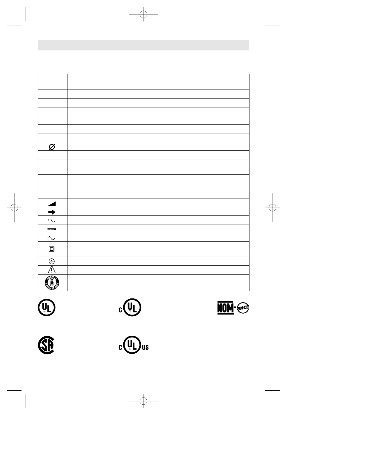
IMPORTANT: Some of the following symbols may be used on your tool. Please study them
and learn their meaning. Proper interpretation of these symbols will allow you to operate the
tool better and safer.
Symbol Name Designation/Explanation
V Volts Voltage (potential)
A Amperes Current
Hz Hertz Frequency (cycles per second)
W Watt Power
kg Kilograms Weight
min Minutes Time
s Seconds Time
Diameter Size of drill bits, grinding wheels, etc.
n
0
No load speed Rotational speed, at no load
.../min Revolutions or reciprocation per minute Revolutions, strokes, surface speed,
orbits etc. per minute
0 Off position Zero speed, zero torque...
1, 2, 3, ... Selector settings Speed, torque or position settings.
I, II, III, Higher number means greater speed
Infinitely variable selector with off Speed is increasing from 0 setting
Arrow Action in the direction of arrow
Alternating current Type or a characteristic of current
Direct current Type or a characteristic of current
Alternating or direct current Type or a characteristic of current
Class II construction Designates Double Insulated
Construction tools.
Earthing terminal Grounding terminal
Warning symbol Alerts user to warning messages
Ni-Cad RBRC seal Designates Ni-Cad battery recycling
program
Symbols
0
This symbol designates
that this tool is listed by
Underwriters Laboratories.
This symbol designates
that this tool is listed by
the Canadian Standards
Association.
This symbol designates
that this tool is listed to
Canadian Standards by
Underwriters Laboratories.
This symbol
designates
that
this tool
complies
to NOM
Mexican
Standards.
This symbol designates
that this tool is listed by
Underwriters Laboratories,
and listed to Canadian
Standards by Underwriters
Laboratories.
BM 3609929818 3/03 3/10/03 8:42 AM Page 6
-7-
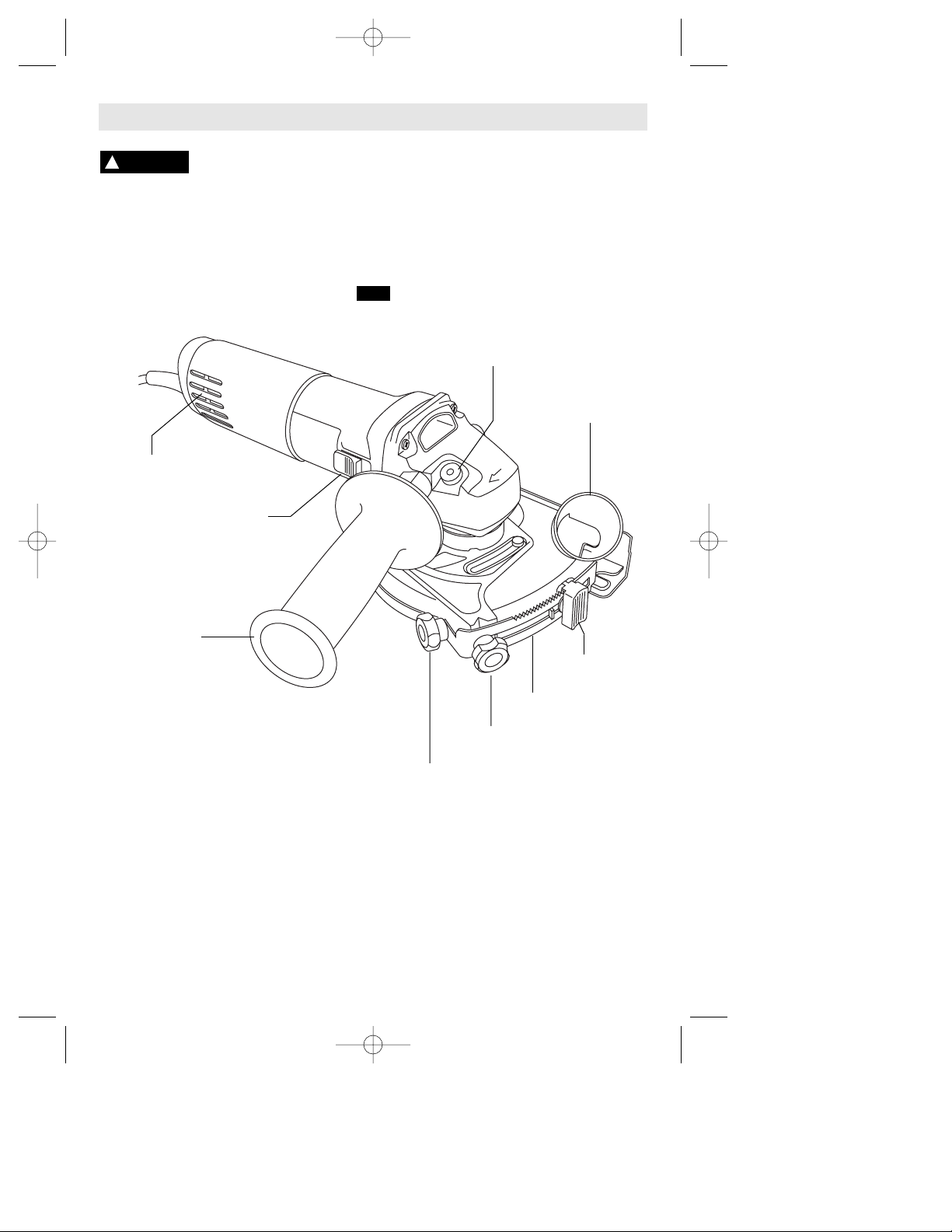
Functional Description and Specifications
Disconnect the plug from the power source before making any
assembly, adjustments or changing accessories. Such preventive safety
measures reduce the risk of starting the tool accidentally.
!
WARNING
Tuckpointer
Model number 1775E
Abrasive wheel diameter 5" (127 mm)
NOTE: For tool specifications refer to the nameplate on your tool.
SPINDLE
LOCK
AUXILIARY
HANDLE
GUARD COVER
KNOB
DEPTH ADJUST
LOCK KNOB
DEPTH
SCALE
ADJUSTABLE
DEPTH STOP
DUST
PORT
SWITCH
BUTTON
VENTILATION
OPENINGS
FIG. 1
BM 3609929818 3/03 3/10/03 8:42 AM Page 7
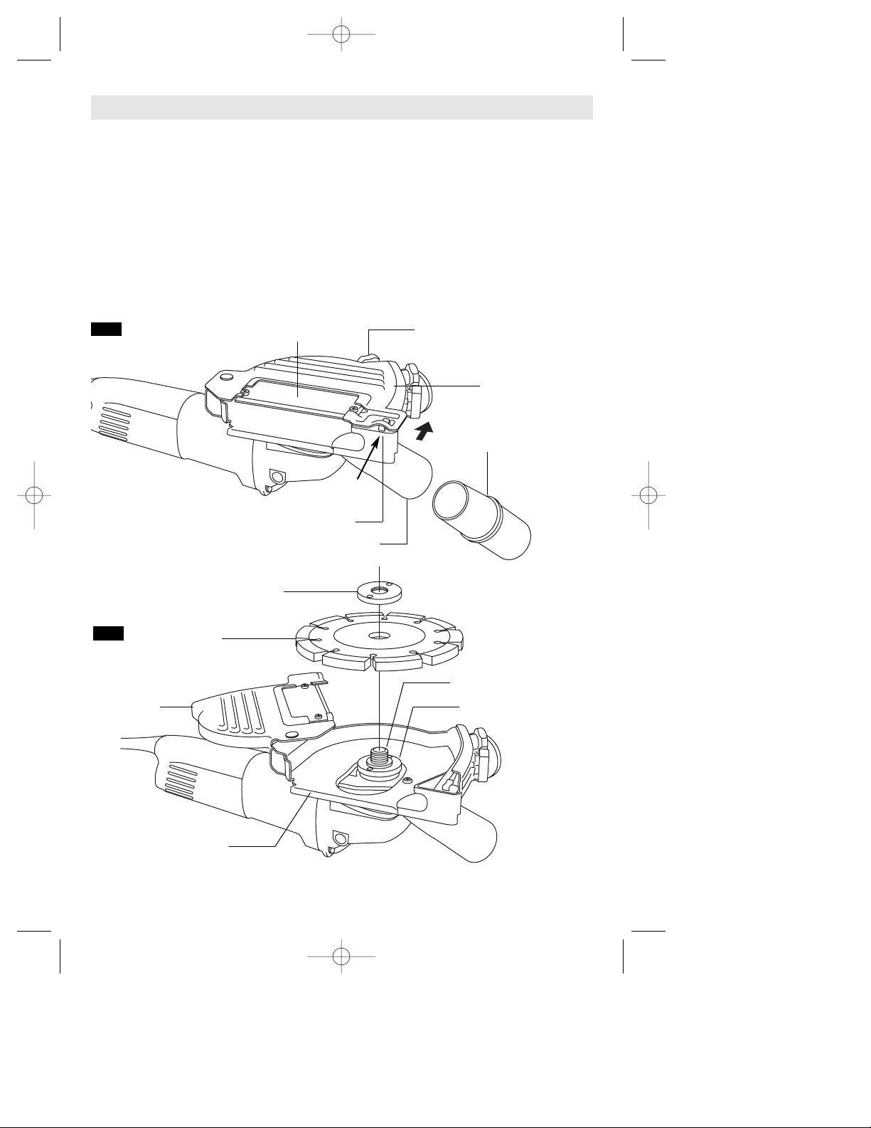
REMOVING AND INSTALLING WHEELS
1. Loosen and remove guard cover lock
knob (Fig. 2).
2. Push raised portion of guard cover near
locking clip (Fig. 2) in direction of arrow to
unlock guard cover, and swing cover out of
the way (Fig. 3).
3. Depress the spindle lock to prevent the
wheel form rotating (Fig. 1).
4. Loosen the lock nut with the wrench
provided, and remove lock nut and abrasive
wheel (Fig. 3).
5. Clean backing flange, spindle, lock nut,
and guard.
6. Place new wheel onto the spindle.
Depress spindle lock and thread lock nut
onto spindle and securely tighten lock nut
with the wrench provided.
7. Return guard cover back to it’s original
position and push into locking clip to secure
guard cover in place (Fig. 2).
8. Replace guard cover knob and securely
tighten knob (Fig. 2).
-8-
Assembly
FIG. 3
ABRASIVE
WHEEL
GUARD
COVER
LOCK NUT
SPINDLE
BACKING FLANGE
GUARD COVER KNOB
LOCKING CLIP
VIEWING
WINDOW
GUARD
COVER
FIG. 2
DUST PORT
VACUUM HOSE
ADAPTER
OPEN
HERE
WHEEL
GUARD
BM 3609929818 3/03 3/10/03 8:42 AM Page 8
SLIDE ON-OFF SWITCH WITH LOCK
The tool is switched “ON” by the switch
button located at the side of the motor
housing. The switch can be locked in the
“ON” position, a convenience for long
grinding operations.
TO TURN THE TOOL “ON” without locking
it, slide the switch button forward by
applying pressure ONLY at the REAR
portion of the button. When pressure is
released the switch button will snap to
“OFF” position.
TO LOCK THE SWITCH “ON”, slide the
switch button forward and press “IN” the
FRONT portion.
TO UNLOCK THE SWITCH, simply press
and release the REAR portion of the button.
Switch is spring loaded and will snap back
automatically.
Hold the tool with both
hands while starting the
tool, since torque from the motor can cause
the tool to twist.
Start the tool before applying to work and let
the tool come to full speed before
contacting the workpiece. Lift the tool from
the work before releasing the switch. DO
NOT turn the switch “ON” and “OFF” while
the tool is under load; this will greatly
decrease the switch life.
CONSTANT RESPONSE CIRCUITRY
The internal electronic feedback system
provides a "soft start", which will reduce the
stresses that occur from a high torque start.
The system also helps to keep the no load
speed virtually constant between no-load
and load conditions.
OVERLOAD PROTECTION
Your tool is equipped with overload
protection to protect the motor. If the tool
stops during operation TURN OFF SWITCH
IMMEDIATELY and allow the motor to cool
for about 30 seconds by running at no-load.
If the overload protection stops the tool
repeatedly, excessive force is causing the
tool to overload. Don't press so hard and let
the tool do the work.
SERVICE MINDER™ BRUSHES
Eliminates quess work, stops the tool when
preventive maintenance is required.
ADJUSTABLE DEPTH STOP
Your tool is equipped with an adjustable stop.
Your cutting depth can be pre-set and/or
repeated by using the depth stop (Fig. 1).
1. Loosen the depth stop lock knob.
2. Depress stop button, move to desired
position on depth bracket, and release button
to secure stop in place.
3. Place foot against workpiece, push down on
tool until it stops.
4. To secure and hold foot and guard
assembly at desired depth of cut. Move foot to
desired depth of cut and securely tighten the
depth stop lock knob.
WHEEL GUARD
Wheel guard must be
attached when using
abrasive wheels. Always keep wheel guard
between you and your work while grinding.
Position the wheel guard such that the dust
port does not interfere with the On/Off
switch.
To adjust guard, loosen clamp screw and
rotate guard to desired position, and
securely tighten screw. Always keep the
wheel guard between you and your work
when during operation.
DUST EXTRACTION
This tool must only be used
with a dust extraction
system. In addition, always wear approved
dust mask.
Your tool is equipped with a dust port for
dust extraction. To use this feature, insert
adapter into dust port (Fig. 2), then insert
vacuum hose (optional accessory) into the
adapter and connect the opposite end of the
hose to a shop vacuum cleaner.
Always make sure the vacuum cleaner that
you use is designed for extraction of
masonry dust.
AUXILIARY HANDLE
The auxiliary handle, used to guide and
balance the tool can be bolted to either side
of the spindle housing depending on
personal preference and comfort. Always
use the auxiliary handle for maximum control
and ease of operation.
-9-
!
WARNING
Operating Instructions
!
WARNING
!
WARNING
BM 3609929818 3/03 3/10/03 8:42 AM Page 9
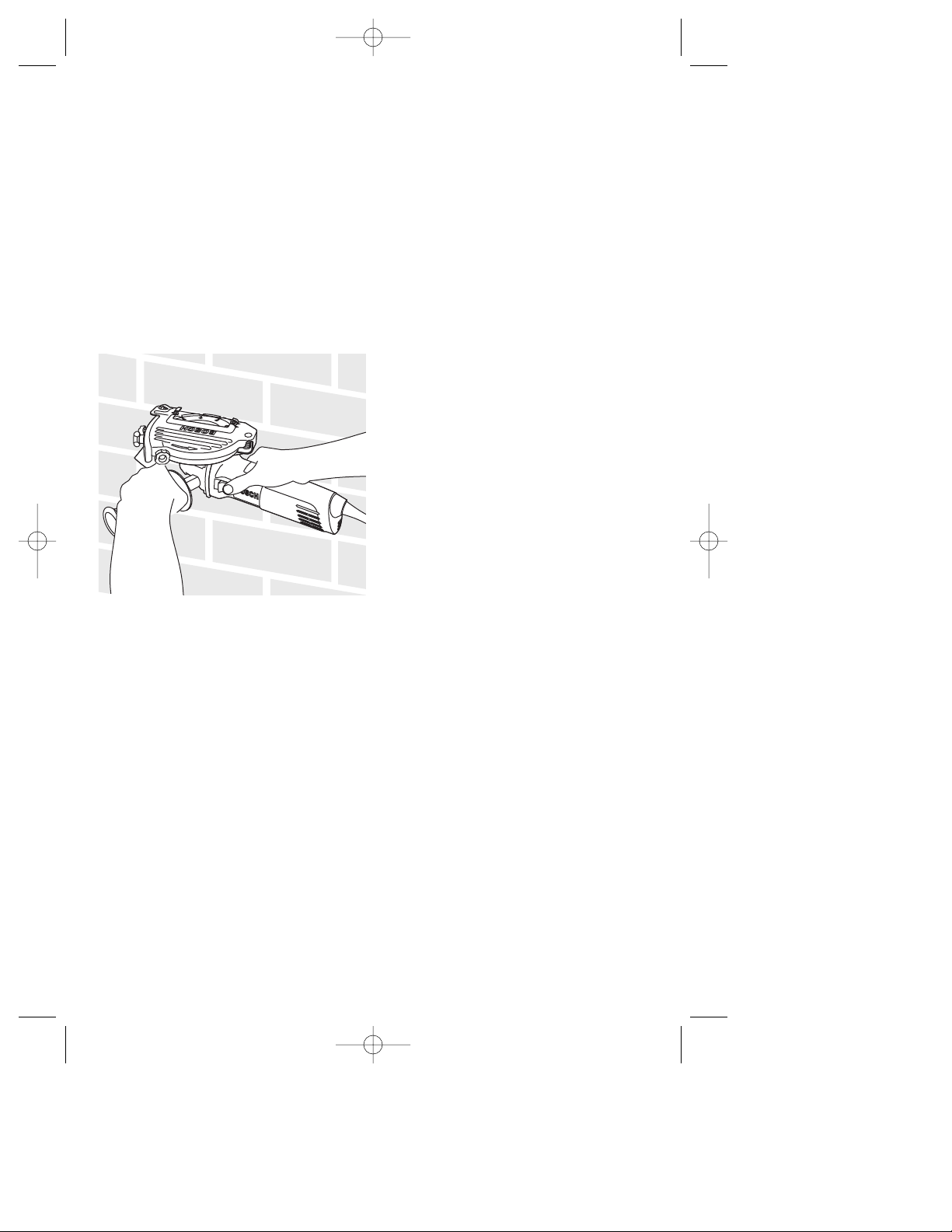
This tool is intended to be used as a
tuckpointer. It is used to remove deteriorating
mortar joints so that they can be replaced
with new mortar.
For best tuckpointing results use 1/4” thick
dry diamond segmented wheel.
Use the adjustable depth stop to obtain the
desired depth of mortar removal. The
tuckpointer is held in the upside position so
that the user can easily see the joint during
operation.
Allow the tool to reach full speed before
applying it to the workpiece surface.
Hold the tool with both hands and apply the
abrasive wheel to the mortar surface.
If this tuckpointer is being used as a small
abrasive cutoff machine, the tool is only
approved for cutting or scoring masonry
products like:
Concrete, cinder blocks, bricks, and stone.
ABRASIVE WHEELS
Use type 1 silicon carbide wheels for cutting
masonry.
Use dry diamond wheels for cutting
concrete. Dry diamond wheel stay cooler,
clogs less and last longer.
1 Before running a cut-off machine, inspect
the cutting wheel for chips or cracks.
Replace bad wheels immediately. New
wheels should be run in at no load or at least
a minute in direction away from the
presence of other people. Imperfect wheels
will normally break apart during this time.
2. An abrasive cut-off machine must NEVER
be operated without the attached guard
secured in place. The guard should be
rotated into the position where maximum
protection is provided for the operator from
sparks and wheel periphery.
3. Proper apparel for operating the tool
includes eye protection, leather gloves, dust
mask and a shop apron.
4. With the tool in the "OFF" position,
become familiar with handling the tool.
Control the head of the tool with the side
handle. Control the cutting edge of the
wheel with the switch handle. Always use
both hands when operating the tool.
5. Never drop the tool. Set the tool down
gently, but never on the wheel.
6. CUTTING CONCRETE will throw large
amounts of dust into the surrounding
area.
Protective dust masks are strongly
recommended for breathing protection for
the operator and other nearby workers.
7. Due to the size and weight of the cut-off
machine it is not recommended to be used
overhead or in any position that would not
allow proper control. Ladders or scaffolding
are not considered solid support structures.
8. Avoid overloading tool. Do not allow the
wheel to bind or stall. Many cuts, especially
into solid concrete, require successive
passes. Do not expose any more abrasive
wheel than necessary to cut with normal
amount of pressure applied to tool. Begin
cutting from the edge of the material,
starting with about 1" wheel exposed. Do
not force the tool; load it normally.
Depending on material hardness and
density, make successively deeper passes
until cut is complete.
-10-
BM 3609929818 3/03 3/10/03 8:42 AM Page 10
 Loading...