

Page 1
Operating/Safety Instructions
Consignes de fonctionnement/sécurité
Instrucciones de funcionamiento
y seguridad
1659
1661
IMPORTANT: IMPORTANT : IMPORTANTE:
Read Before Using Lire avant usage Leer antes de usar
For English Parlez-vous français? ¿Habla español?
See page 2 Voir page 15 Ver página 28
Consumer Information
Renseignement des consommateurs
Información para el consumidor
Toll Free Number: Appel gratuit : Número de teléfono gratuito:
1-877-BOSCH99 (1-877-267-2499) http://www.boschtools.com.
BM 2610998757 11/01 11/2/01 3:32 PM Page 1
Page 2

Read and understand all instructions. Failure to follow all instructions listed
below, may result in electric shock, fire and/or serious personal injury.
SAVE THESE INSTRUCTIONS
-2-
Work Area
Keep your work area clean and well lit.
Cluttered benches and dark areas invite
accidents.
Do not operate power tools in explosive
atmospheres, such as in the presence of
flammable liquids, gases, or dust. Power
tools create sparks which may ignite the
dust or fumes.
Keep by-standers, children, and visitors
away while operating a power tool.
Distractions can cause you to lose control.
Electrical Safety
Do not abuse the cord. Never use the
cord to carry the tool. Keep cord away
from heat, oil, sharp edges, or moving
parts. Replace damaged cords immediately. Damaged cords may create a
fire.
A battery operated tool with integral
batteries or a separate battery pack must
be recharged only with the specified
charger for the battery. A charger that may
be suitable for one type of battery may
create a risk of fire when used with another
battery.
Use battery operated tool only with
specifically designated battery pack. Use
of any other batteries may create a risk of
fire.
Personal Safety
Stay alert, watch what you are doing, and
use common sense when operating a
power tool. Do not use tool while tired or
under the influence of drugs, alcohol, or
medication. A moment of inattention while
operating power tools may result in serious
personal injury.
Dress properly. Do not wear loose
clothing or jewelry. Contain long hair.
Keep your hair, clothing, and gloves away
from moving parts. Loose clothes, jewelry,
or long hair can be caught in moving parts.
Avoid accidental starting. Be sure switch
is in the locked or off position before
inserting battery pack. Carrying tools with
your finger on the switch or inserting the
battery pack into a tool with the switch on
invites accidents.
Remove adjusting keys or wrenches
before turning the tool on. A wrench or a
key that is left attached to a rotating part of
the tool may result in personal injury.
Do not overreach. Keep proper footing
and balance at all times. Proper footing
and balance enable better control of the tool
in unexpected situations.
Use safety equipment. Always wear eye
protection. Dust mask, non-skid safety
shoes, hard hat, or hearing protection must
be used for appropriate conditions.
Tool Use and Care
Use clamps or other practical way to
secure and support the workpiece to a
stable platform. Holding the work by hand
or against your body is unstable and may
lead to loss of control.
Do not force tool. Use the correct tool for
your application. The correct tool will do
the job better and safer at the rate for which
it is designed.
Do not use tool if switch does not turn it
on or off. A tool that cannot be controlled
with the switch is dangerous and must be
repaired.
Disconnect battery pack from tool or
place the switch in the locked or off
position before making any adjustments,
changing accessories, or storing the tool.
Such preventive safety measures reduce the
risk of starting the tool accidentally.
Store idle tools out of reach of children
and other untrained persons. Tools are
dangerous in the hands of untrained users.
When battery pack is not in use, keep it
away from other metal objects like: paper
clips, coins, keys, nails, screws, or other
!
WARNING
General Safety Rules
For All Battery Operated Tools
BM 2610998757 11/01 11/2/01 3:32 PM Page 2
Page 3

-3-
Safety Rules for Circular Saws
small metal objects that can make a
connection from one terminal to another.
Shorting the battery terminals together may
cause sparks, burns, or a fire.
Maintain tools with care. Keep cutting
tools sharp and clean. Properly maintained
tools with sharp cutting edge are less likely
to bind and are easier to control.
Check for misalignment or binding of
moving parts, breakage of parts, and any
other condition that may affect the tool's
operation. If damaged, have the tool
serviced before using. Many accidents are
caused by poorly maintained tools.
Use only accessories that are recommended by the manufacturer for your
model. Accessories that may be suitable for
one tool may create a risk of injury when
used on another tool.
Service
Tool service must be performed only by
qualified repair personnel. Service or
maintenance performed by unqualified
personnel may result in a risk of injury.
When servicing a tool, use only identical
replacement parts. Follow instructions in
the Maintenance section of this manual.
Use of unauthorized parts or failure to follow
Maintenance Instructions may create a risk
of shock or injury.
Keep hands away from
cutting area and blade.
Keep your second hand on auxiliary handle,
or motor housing. If both hands are holding
the saw, they cannot be cut by the blade. Hold
the saw firmly to prevent loss of control. Figures
in this manual illustrate typical hand support of
the saw. NEVER place your hand behind the
saw blade since kickback could cause the saw
to jump backwards over your hand.
Keep your body positioned to either side of
the saw blade, but not in line with the saw
blade. KICKBACK could cause the saw to
jump backwards. (See “Causes and Operator
Prevention of Kickback.”)
Do not reach underneath the work. The
guard cannot protect you from the blade below
the work. Do not attempt to remove cut
material when blade is moving.
Check lower guard for proper closing before
each use. Do not operate saw if lower guard
does not move freely and close instantly.
Never clamp or tie the lower guard into the
open position. If saw is accidentally dropped,
lower guard may be bent. Raise the lower
guard only with the Lower Guard Lift Lever and
make sure it moves freely and does not touch
the blade or any other part, in all angles and
depths of cut.
Check the operation of the lower guard
spring. If the guard and the spring are not
operating properly, they must be serviced
before use. Lower guard may operate
sluggishly due to damaged parts, gummy
deposits, or a buildup of debris. Disconnect
battery pack from tool. Periodically remove the
blade, clean the upper, lower guards and the
hub area with kerosene and wipe it dry, or blow
it clean with compressed air.
Lower guard should be retracted manually
only for special cuts such as “Pocket Cuts”
and “Compound Cuts”. Raise lower guard
by Lower Guard Lift Lever. As soon as blade
enters the material, lower guard must be
released. For all other sawing, the lower guard
should operate automatically.
Always observe that the lower guard is
covering the blade before placing saw down
on bench or floor. An unprotected, coasting
blade will cause the saw to walk backwards,
cutting whatever is in its path. Be aware of the
time it takes for the blade to stop after switch is
released.
NEVER hold piece being cut in your hands
or across your leg. It is important to support
the work properly to minimize body exposure,
blade binding, or loss of control.
Hold tool by the insulated gripping surfaces
when performing an operation where the
cutting tool may contact hidden wiring or it
own cord. Contact with a "live" wire will also
make exposed metal parts of the tool “live” and
shock the operator.
DANGER
!
BM 2610998757 11/01 11/2/01 3:32 PM Page 3
Page 4
When ripping always use a rip fence or
straight edge guide. This improves accuracy
of cut and reduces the chance for blade
binding.
Always use blades with correct size and
shape (diamond vs. round) arbor holes.
Blades that do not match the mounting
hardware of the saw will run eccentrically,
causing loss of control and will not allow proper
vari-torque engagement.
Never use damaged or incorrect blade
washers or bolts. The blade washers and bolt
were specially designed for your saw, for
optimum performance and safety of operation.
The blade washers and the bolt on your saw
have been designed to work as a “VARITORQUE CLUTCH”. Understand the operation
and settings of the VARI-TORQUE CLUTCH,
because the proper setting of the CLUTCH,
combined with firm handling of the saw will
allow you to control KICKBACK.
Do not run the saw while carrying it at your
side. Lower guard may be opened by a
contact with your clothing. Accidental
contact with the spinning saw blade could
result in serious personal injury.
Depending upon use, the switch may not
last the life of the saw. If the switch should
fail in the “OFF” position, the saw may not
start. If it should fail while the saw is
running, the saw may not shut off. If either
occurs, do not use until repaired.
This circular saw should not be mounted to
a table and converted to a table saw.
Circular saws are not designed or intended to
be used as table saws.
CAUSES AND OPERATOR PREVENTION OF
KICKBACK:
Kickback is a sudden reaction to a pinched,
bound or misaligned saw blade, causing an
uncontrolled saw to lift up and out of the
workpiece toward the operator.
When the blade is pinched or bound tightly by
the kerf closing down, the blade stalls and the
motor reaction drives the unit rapidly back
toward the operator.
If the blade becomes twisted or misaligned in
the cut, the teeth at the back edge of the blade
can dig into the top surface of the wood
causing the blade to climb out of the kerf and
jump back toward the operator.
Kickback is the result of tool misuse and/or
incorrect operating procedures or conditions
and can be avoided by taking proper
precautions as given below:
Maintain a firm grip with both hands on the
saw and position your body and arm to
allow you to resist KICKBACK forces.
KICKBACK forces can be controlled by the
operator, if proper precautions are taken.
When blade is binding, or when interrupting
a cut for any reason, release the trigger and
hold the saw motionless in the material until
the blade comes to a complete stop. Never
attempt to remove the saw from the work or
pull the saw backward while the blade is in
motion or KICKBACK may occur. Investigate
and take corrective action to eliminate the
cause of blade binding. Wet lumber, green
lumber or pressure treated lumber require
special attention during cutting operation to
prevent KICKBACK. Avoid cutting nails. Inspect
for and remove all nails from lumber before
cutting.
When restarting a saw in a workpiece,
center the saw blade in the kerf and check
that saw teeth are not engaged into the
material. If saw blade is binding, it may walk
up or KICKBACK from the workpiece as the
saw is restarted.
Support large panels to minimize the risk of
blade pinching and KICKBACK. Large panels
tend to sag under their own weight. Supports
must be placed under the panel on both sides,
near the line of cut and near the edge of the
panel. See “Cutting Large Sheets” in this
manual.
-4-
KICKBACK
BM 2610998757 11/01 11/2/01 3:32 PM Page 4
Page 5
Do not use dull or damaged blade.
Unsharpened or improperly set blades produce
narrow kerf causing excessive friction, blade
binding and KICKBACK.
Blade depth and bevel adjusting locking
knobs must be tight and secure before
making cut. If blade adjustment shifts while
cutting, it may cause binding and KICKBACK.
Using the saw with an excessive depth of cut
setting increases loading on the unit and
susceptibility to twisting of the blade in the kerf.
It also increases the surface area of the blade
available for pinching under conditions of kerf
close down.
Use extra caution when making a “Pocket
Cut” into existing walls or other blind areas.
The protruding blade may cut objects that can
cause KICKBACK.
Some dust created by
power sanding, sawing,
grinding, drilling, and other construction
activities contains chemicals known to
cause cancer, birth defects or other
reproductive harm. Some examples of
these chemicals are:
• Lead from lead-based paints,
• Crystalline silica from bricks and cement
and other masonry products, and
• Arsenic and chromium from chemically-
treated lumber.
Your risk from these exposures varies,
depending on how often you do this type of
work. To reduce your exposure to these
chemicals: work in a well ventilated area,
and work with approved safety equipment,
such as those dust masks that are specially
designed to filter out microscopic particles.
-5-
!
WARNING
Before using battery charger, read all
instructions and cautionary markings on
(1) battery charger, (2) battery pack, and
(3) product using battery.
Use only the charger which accompanied
your product or direct replacement as
listed in the catalog or this manual. Do not
substitute any other charger. Use only Bosch
approved chargers with your product. See
Functional Description and Specifications.
Do not disassemble charger or operate
the charger if it has received a sharp
blow, been dropped or otherwise
damaged in any way. Replace damaged
cord or plugs immediately. Incorrect
reassembly or damage may result in electric
shock or fire.
Do not recharge battery in damp or wet
environment. Do not expose charger to
rain or snow. If battery case is cracked or
otherwise damaged, do not insert into
charger. Battery short or fire may result.
Charge only Bosch approved rechargeable
batteries. See Functional Description and
Specifications. Other types of batteries may
burst causing personal injury and damage.
Charge battery pack in temperatures
above +40 degrees F (4 degrees C) and
below +105 degrees F (41 degrees C).
Store tool and battery pack in locations
where temperatures do not go below 40
degrees F (4 degrees C) or will no exceed
120 degrees F (49 degrees C). Allow
battery pack to return to room
temperature before attempting to
charge.This is important to prevent serious
damage to the battery cells.
Battery leakage may occur under extreme
usage or temperature conditions. Avoid
contact with skin and eyes. The battery
liquid is caustic and could cause chemical
burns to tissues. If liquid comes in contact
with skin, wash quickly with soap and water,
then with lemon juice or vinegar. If the liquid
contacts your eyes, flush them with water for
a minimum of 10 minutes and seek medical
attention.
Place charger on flat non-flammable
surfaces and away from flammable
materials when re-charging battery pack.
The charger and battery pack heat during
charging. Carpeting and other heat insulating
surfaces block proper air circulation which
may cause overheating of the charger and
battery pack. If smoke or melting of the
case are observed unplug the charger
immediately and do not use the battery pack
or charger.
Use of an attachment not recommended or sold by Bosch may result in a
risk of fire, electric shock or injury to
persons.
Battery/Charger
BM 2610998757 11/01 11/2/01 3:32 PM Page 5
Page 6
-6-
When batteries are not in
tool or charger, keep them
away from metal objects. For example, to
protect terminals from shorting DO NOT
place batteries in a tool box or pocket with
nails, screws, keys, etc. Fire or injury may
result.
DO NOT PUT BATTERIES INTO FIRE OR
EXPOSE TO HIGH HEAT. They may
explode.
!
WARNING
Battery Care
Do not attempt to disassemble the battery or
remove any component projecting from
the battery terminals. Fire or injury may
result. Prior to disposal, protect exposed
terminals with heavy insulating tape to
prevent shorting.
NICKEL-CADMIUM BATTERIES
If equipped with a nickel-cadmium battery,
the battery must be collected, recycled or
disposed of in an environmentally sound
manner.
“The EPA certified RBRC
Battery Recycling Seal on the
nickel-cadmium (Ni-Cd)
battery indicates S-B Power
Tool Company is voluntarily
participating in an industry
program to collect and recycle these
batteries at the end of their useful life, when
taken out of service in the United States or
Canada. The RBRC program provides a
convenient alterative to placing used Ni-Cd
batteries into the trash or the municipal
waste stream, which may be illegal in your
area.
Please call 1-800-8-BATTERY for information
on Ni-Cd battery recycling and disposal
bans/restrictions in your area, or return your
batteries to a Skil/Bosch/Dremel Service
Center for recycling. S-B Power Tool
Company’s involvement in this program is
part of our commitment to preserving our
environment and conserving our natural
resources.”
NICKEL-METAL HYDRIDE BATTERIES
If equipped with a nickel-metal hydride
battery, the battery can be disposed of in a
municipal solid waste stream.
!
WARNING
Battery Disposal
BM 2610998757 11/01 11/2/01 3:32 PM Page 6
Page 7
-7-
IMPORTANT: Some of the following symbols may be used on your tool. Please study them
and learn their meaning. Proper interpretation of these symbols will allow you to operate the
tool better and safer.
Symbol Name Designation/Explanation
V Volts Voltage (potential)
A Amperes Current
Hz Hertz Frequency (cycles per second)
W Watt Power
kg Kilograms Weight
min Minutes Time
s Seconds Time
Diameter Size of drill bits, grinding wheels, etc.
n
0
No load speed Rotational speed, at no load
.../min Revolutions or reciprocation per minute Revolutions, strokes, surface speed,
orbits etc. per minute
0 Off position Zero speed, zero torque...
1, 2, 3, ... Selector settings Speed, torque or position settings.
I, II, III, Higher number means greater speed
Infinitely variable selector with off Speed is increasing from 0 setting
Arrow Action in the direction of arrow
Alternating current Type or a characteristic of current
Direct current Type or a characteristic of current
Alternating or direct current Type or a characteristic of current
Class II construction Designates Double Insulated
Construction tools.
Earthing terminal Grounding terminal
Warning symbol Alerts user to warning messages
Ni-Cad RBRC seal Designates Ni-Cad battery recycling
program
Symbols
0
This symbol designates
that this tool is listed by
Underwriters Laboratories.
This symbol designates
that this tool is listed by
the Canadian Standards
Association.
This symbol designates
that this tool is listed to
Canadian Standards by
Underwriters Laboratories.
This symbol
designates
that
this tool
complies
to NOM
Mexican
Standards.
This symbol designates
that this tool is listed by
Underwriters Laboratories,
and listed to Canadian
Standards by Underwriters
Laboratories.
BM 2610998757 11/01 11/2/01 3:32 PM Page 7
Page 8
Functional Description and Specifications
Disconnect battery pack from tool or place the switch in the locked or
off position before making any assembly, adjustments or changing
accessories. Such preventive safety measures reduce the risk of starting the tool
accidentally.
!
WARNING
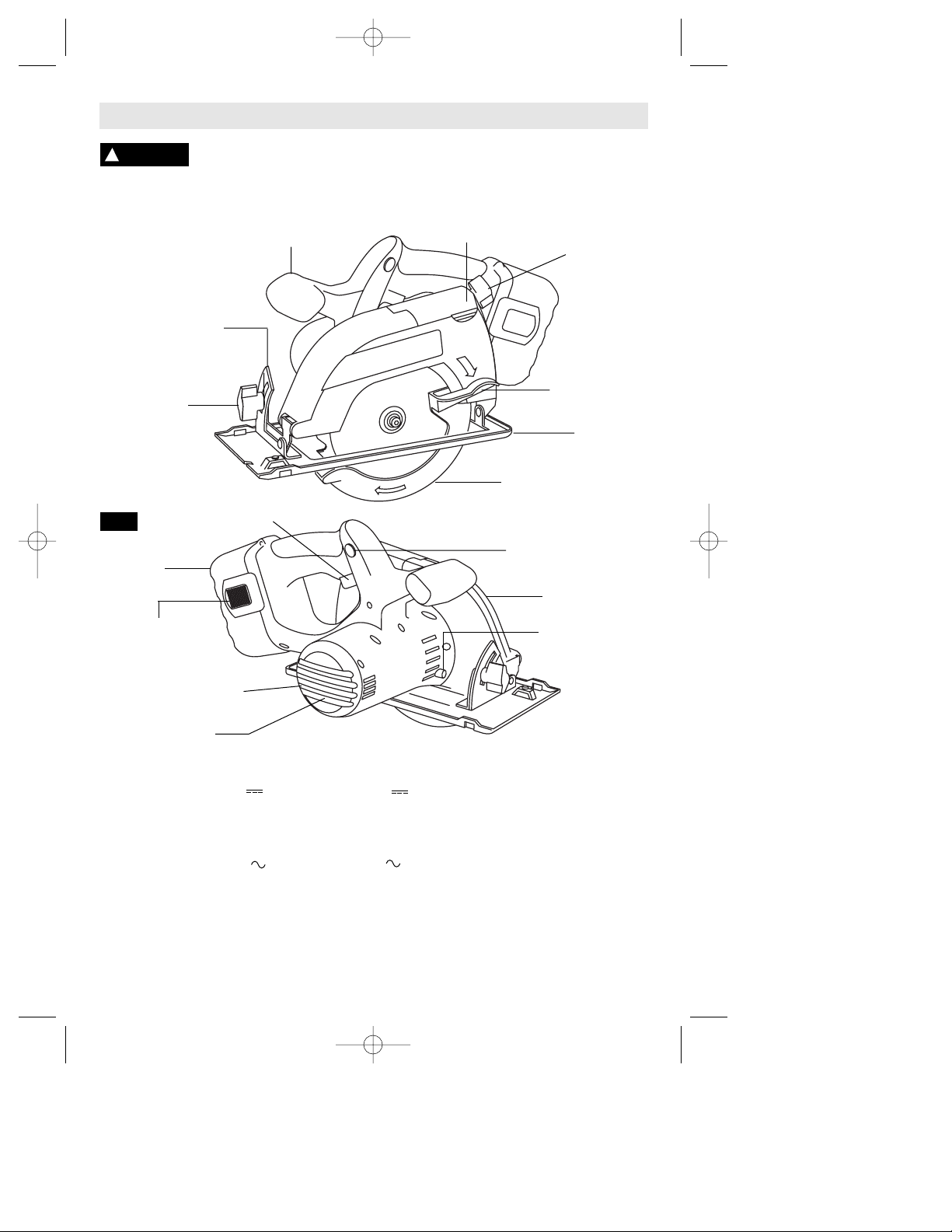
FOOT
LOWER
GUARD LIFT
LEVER
AUXILIARY
HANDLE
BEVEL
ADJUSTMENT
KNOB
CALIBRATED BEVEL
QUADRANT
DUST PORT
COVER
DEPTH
ADJUSTMENT
KNOB
Cordless
Circular Saws
UPPER GUARD
LOWER
GUARD
LOCK
BUTTON
FIG. 1
BATTERY PACK
RELEASE TABS
BATTERY
PACK
SAFETY SWITCH
RELEASE
BUTTON
TRIGGER
BLADE WRENCH &
STORAGE AREA
VENTILATION
OPENINGS
Tool Maximum Capacities
Model number 1659 1661 Blade 5-3/8"
Voltage rating 18 V 14.4 V Depth of cut at 90° 1-5/8"
No load speed n
0
3,600/min n0 3,600/min Depth of cut at 45° 1-1/4"
Charge time 1 hr 1 hr
Charger BC003,4,6, & BC016 BC001-6 & BC016 ATTENTION: Use only thin
Battery pack BAT025 BAT040 kerf blades designed for
Voltage rating 120 V 60 Hz 120 V 60 Hz Cordless Circular Saws.
Amperage rating 2.5 A 1.9 A
BC006 charger requires 12 V DC input
NOTE: ONLY USE CHARGERS LISTED ABOVE
For replacement blades we recommend Bosch Cordless Circular saw blades. Their thin kerf
and tooth design deliver the best speed, quality of cut, and reduce battery drain. Use of
standard blades will substantially affect the performance and reduce run-time.
-8-
BM 2610998757 11/01 11/2/01 3:32 PM Page 8
Page 9
-9-
Assembly
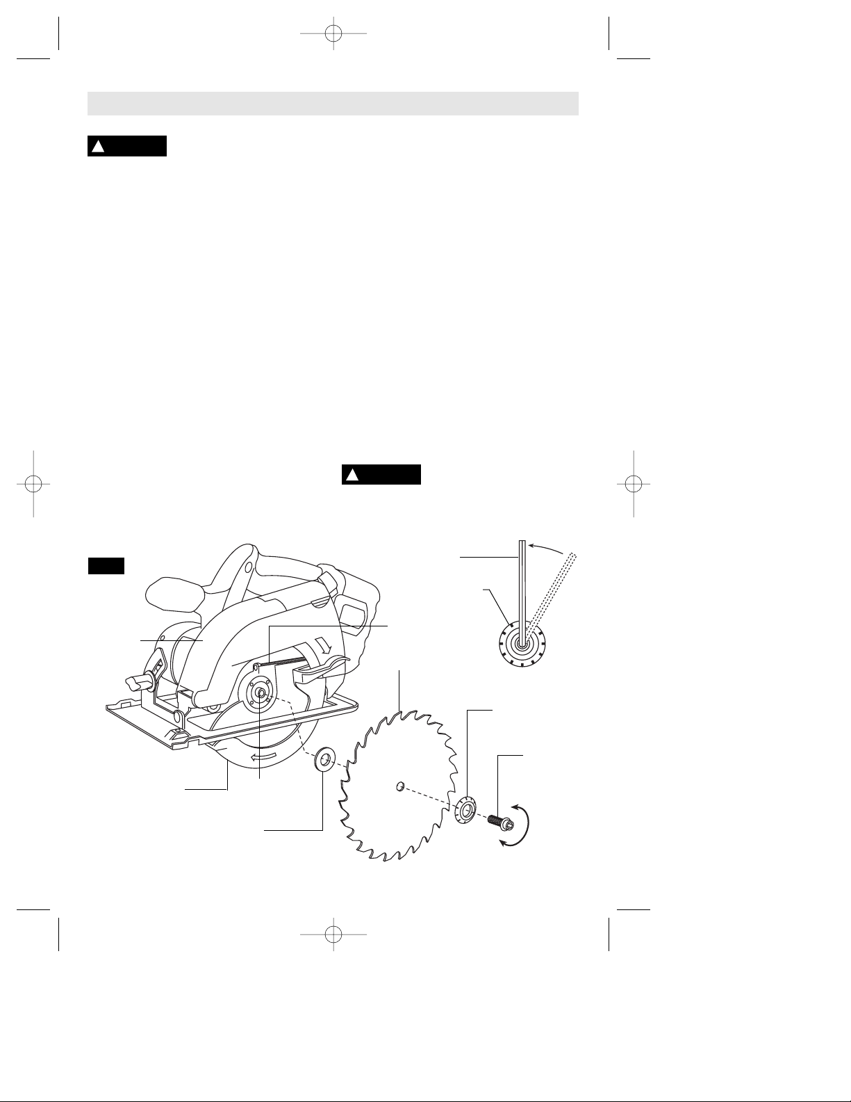
ATTACHING THE BLADE
Disconnect battery pack
from tool or place the
switch in the locked or off position before
making any assembly, adjustments or
changing accessories. Such preventive
safety measures reduce the risk of starting
the tool accidentally.
1. Turn BLADE STUD with wrench provided
clockwise and remove BLADE STUD and
OUTER WASHER (Fig. 2). If the shaft moves
while attempting to loosen the blade stud
press the lock button.
2. Retract the lower guard all the way up into
the upper guard. While retracting the lower
guard, check operation and condition of the
LOWER GUARD SPRING.
3. Make sure the saw teeth and arrow on the
blade point in the same direction as the arrow
on the lower guard.
4. Slide blade through slot in the foot and
mount it against the INNER WASHER on the
shaft. Be sure the large diameter of the OUTER
washer lays flush against the blade.
5. Reinstall OUTER WASHER and tighten
BLADE STUD finger tight. The face of outer
washer has marks on it that will help you
properly adjust the blade stud. Press lock
button to lock shaft and TIGHTEN BLADE
STUD COUNTER-CLOCKWISE ONE MARK
ON BLADE WASHER WITH THE WRENCH
PROVIDED.
Do not use wrenches with longer handles,
since it may lead to over tightening of the
blade stud.
VARI-TORQUE CLUTCH
This clutching action is provided by the friction
of the OUTER WASHER against the BLADE
and permits the blade shaft to turn when the
blade encounters excessive resistance. When
the BLADE STUD is properly tightened (as
described in No. 5 of Attaching The Blade), the
blade will slip when it encounters excessive
resistance, thus reducing saw’s tendency to
KICKBACK.
One setting may not be sufficient for cutting all
materials. If excessive blade slippage occurs,
tighten the blade stud a fraction of a turn more
(less than 1/8 turn). OVERTIGHTENING THE
BLADE STUD NULLIFIES THE EFFECTIVENESS OF THE CLUTCH.
DUST EXTRACTION
Your tool is equipped is with a dust port for
dust and chip extraction. To use this feature,
open dust port cover and attach vacuum hose
(optional accessory) to the dust port, and
connect opposite end the hose to a shop
vacuum cleaner.
To prevent personal injury,
always position vacuum
hose so that it does not interfere with the
lower guard, or the cutting operation at all
settings.
!
WARNING
FIG. 2
TIGHTEN
LOOSEN
BLADE
STUD
LOWER
GUARD
SPRING
OUTER WASHER
Large Diameter
Faces Blade
INNER WASHER
Large Diameter
Faces Blade
BLADE
LOWER
GUARD
BLADE
SHAFT
UPPER
GUARD
!
WARNING
WRENCH
OUTER WASHER
MARK
BM 2610998757 11/01 11/2/01 3:32 PM Page 9
Page 10
-10-
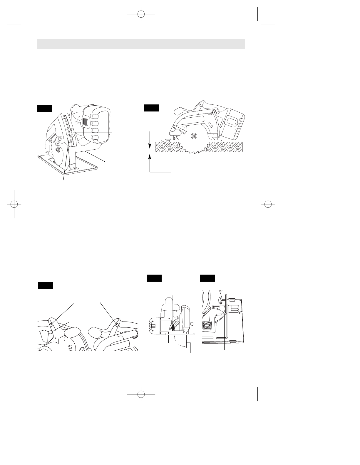
Disconnect battery pack from tool. Loosen
the depth adjustment knob located on the
back side of the upper guard. Hold the foot
down with one hand and raise or lower saw
by the handle. Tighten knob at the depth
setting desired. Check desired depth (Fig. 3).
Not more than one tooth length of the blade
should extend below the material to be cut,
for minimum splintering (Fig. 4).
SAFETY SWITCH
The safety switch is designed to prevent
accidental starts. To operate safety switch,
press the release button with your thumb on
either side of handle to disengage the lock,
then pull the trigger (Fig. 5). When the trigger
is released the button will engage the safety
switch automatically, and the trigger will no
longer operate. (See Switch & General Cuts
on page 10.)
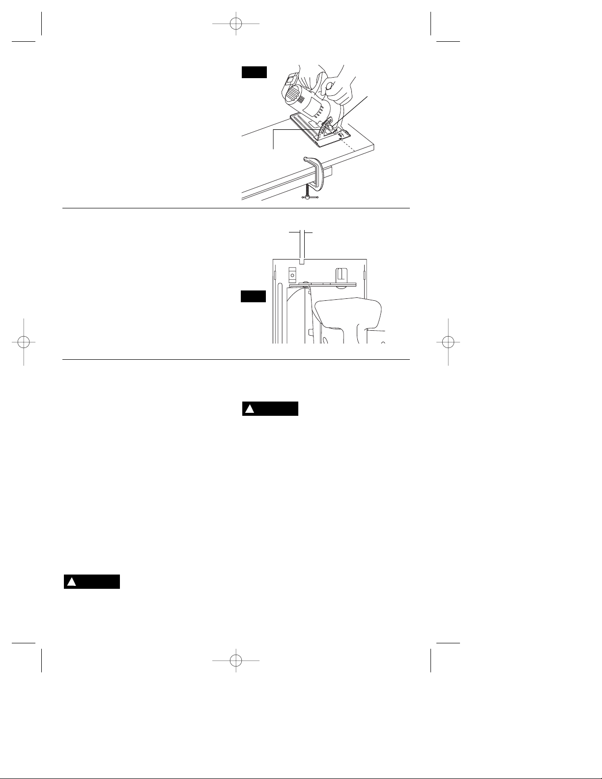
90° CUTTING ANGLE CHECK
Disconnect battery pack from tool. Set foot to
maximum depth of cut setting. Loosen bevel
adjustment knob, set to 0° on quadrant,
retighten knob and check for 90° angle
between the blade and bottom plane of foot
with a square (Fig. 6). If adjustment is
necessary, tilt foot to 45°, tighten bevel
adjustment wing nut and bend "TAB" with an
adjustable wrench or pliers (Fig. 7).
DEPTH ADJUSTMENT
Operating Instructions
0
2
1
90°
FIG. 3
FIG. 4
FIG. 5
FIG. 7
FIG. 6
ONE TOOTH LENGTH SHOULD
PENETRATE WOOD FOR
MINIMUM SPLINTERING
DEPTH
ADJUSTMENT
KNOB
CALIBRATED DEPTH
BRACKET
BLADE WRENCH
& STORAGE
AREA
SAFETY SWITCH
RELEASE
BUTTON
TAB
BEVEL
ADJUSTMENT
KNOB
BLADE
TRIGGER
FOOT
BM 2610998757 11/01 11/2/01 3:32 PM Page 10
Page 11
BEVEL ADJUSTMENT
Disconnect battery pack from tool. The foot
can be adjusted up to 50° by loosening the
bevel adjustment knob at the front of the
saw. Align to desired angle on calibrated
quadrant. Then tighten bevel adjustment
knob (Fig. 8). Because of the increased
amount of blade engagement in the work and
decreased stability of the foot, blade binding
may occur. Keep the saw steady and the foot
firmly on the workpiece.
-11-
LINE GUIDE
For a straight 90° cut, use right side of notch
in the foot. For 45° bevel cuts, use the left
side (Fig. 9). The cutting guide notch will give
an approximate line of cut. Make sample cuts
in scrap lumber to verify actual line of cut.
This will be helpful because of the number of
different blade types and thicknesses
available. To ensure minimum splintering on
the good side of the material to be cut, face
the good side down.
SWITCH
To turn tool “ON”, squeeze the trigger switch.
To turn the tool “OFF”, release the trigger
switch, which is spring loaded and will return
to the off position automatically.
Your saw should be running at full speed
BEFORE starting the cut, and turned off only
AFTER completing the cut. To increase
switch life, do not turn switch on and off while
cutting.
BRAKE
When the trigger is released it activates the
electrical brake to stop the blade quickly. This
feature is especially useful when making
repetitive cuts.
GENERAL CUTS
Always hold the saw handle with one hand
and the auxiliary handle or housing with the
other.
Always make sure saw foot rests on portion
of work surface that does not drop off.
Always be sure either
hand does not interfere
with the free movement of the lower
guard.
Maintain a firm grip and operate the switch
with a decisive action. Never force the saw.
Use light and continuous pressure.
After completing a cut and
the trigger has been
released, be aware of the necessary time it
takes for the blade to come to a complete
stop during coast down. Do not allow the
saw to brush against your leg or side,
since the lower guard is retractable, it
could catch on your clothing and expose
the blade. Be aware of the necessary
blade exposures that exist in both the
upper and lower guard areas.
When cutting is interrupted, to resume
cutting: squeeze the trigger and allow the
blade to reach full speed, re-enter the cut
slowly and resume cutting.
When cutting across the grain, the fibers of
the wood have a tendency to tear and lift.
Advancing the saw slowly minimizes this
effect. For a finished cut, a cross cut blade or
miter blade is recommended.
!
WARNING
!
WARNING
FIG. 9
45°
BEVEL
CUTS
90°
VERTICAL CUTS
FIG. 8
BEVEL
ADJUSTMENT
KNOB
QUADRANT
BM 2610998757 11/01 11/2/01 3:32 PM Page 11
Page 12
-12-
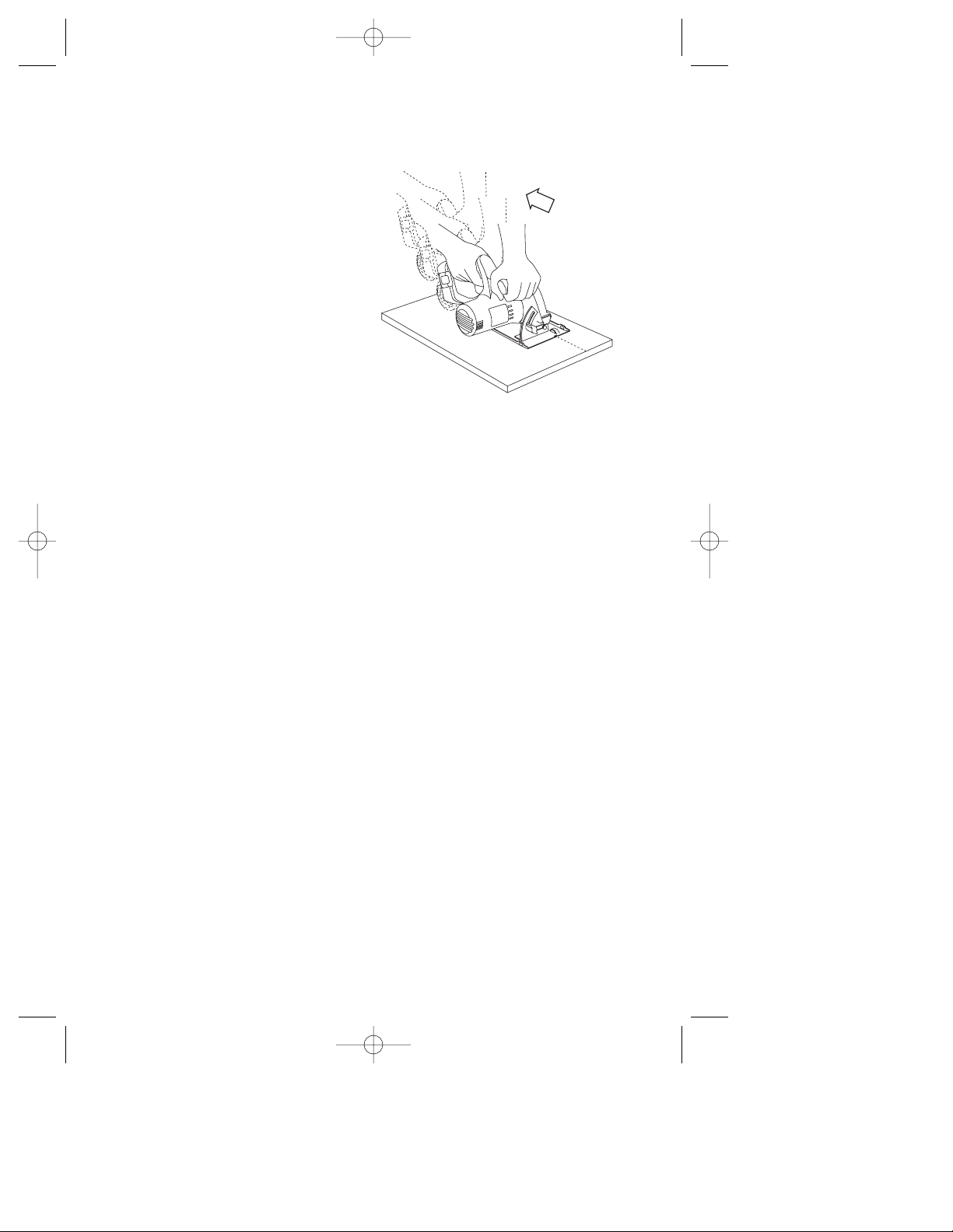
POCKET CUTS
Disconnect battery pack from tool before
making adjustments. Set depth adjust-ment
according to material to be cut. Tilt saw forward
with cutting guide notch lined up with the line
you’ve drawn. Raise the lower guard, using lift
lever and hold the saw by the front and rear
handles (Fig. 10).
With the blade just clearing the material to be
cut, start the motor. Gradually lower the back
end of saw using the front end of the foot as
the hinge point. WARNING: As blade starts
cutting the material, release the lower guard
immediately. When the foot rests flat on the
surface being cut, proceed cutting in forward
direction to end of cut. WARNING: Allow
blade to come to a complete stop before
lifting the saw from cut. Also, never pull the
saw backward since blade will climb out of
the material and KICKBACK will occur. Turn
saw around and finish the cut in the normal
manner, sawing forward. If corners of your
pocket cut are not completely cut through, use
a jigsaw or hand saw to finish the corners.
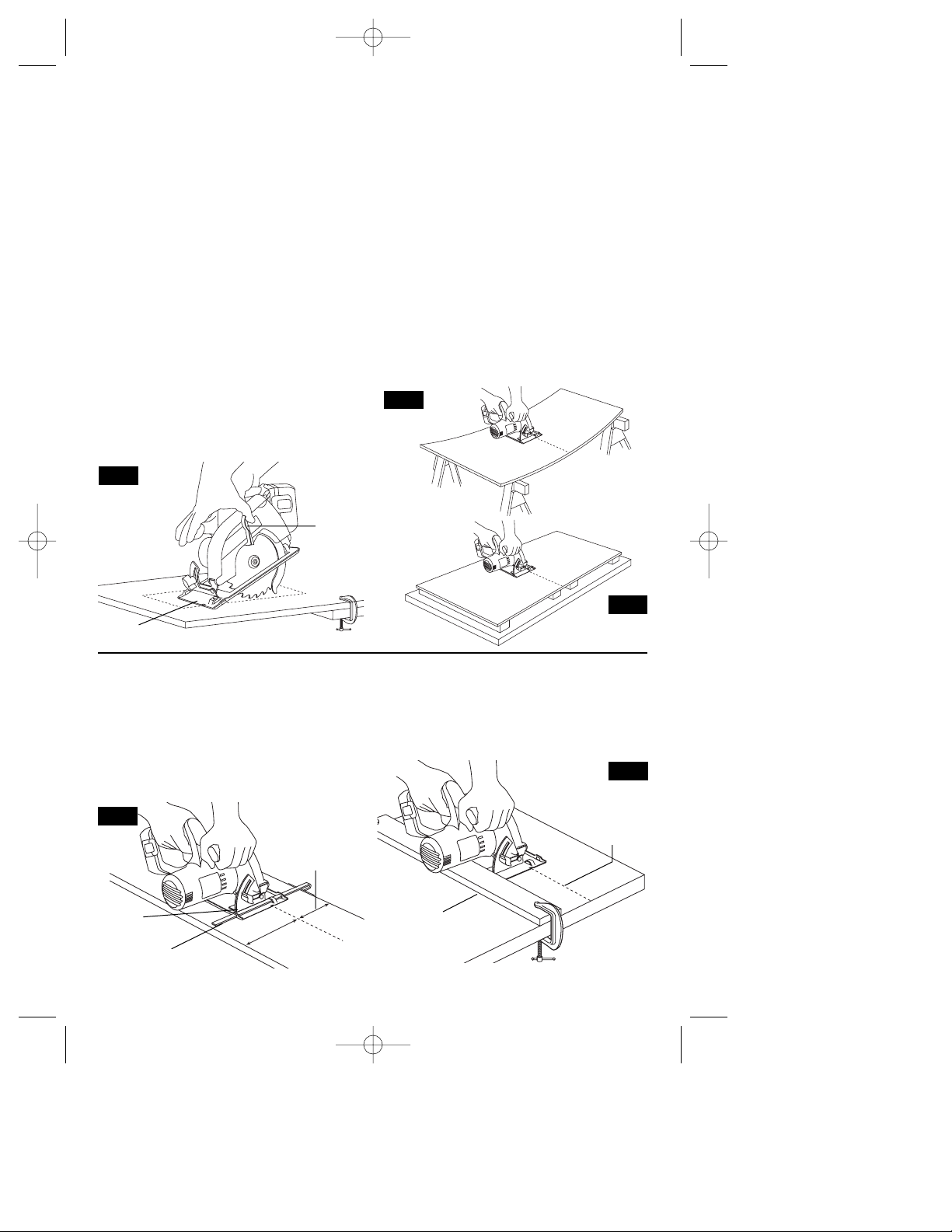
CUTTING LARGE SHEETS
Large sheets and long boards sag or bend,
depending on support. If you attempt to cut
without leveling and properly supporting the
piece, the blade will tend to bind, causing KICKBACK and extra load on the motor (Fig. 11).
Support the panel or board close to the cut, as
shown in (Fig. 12). Be sure to set the depth of
the cut so that you cut through the sheet or
board only and not the table or work bench.
The two-by-fours used to raise and support the
work should be positioned so that the broadest
sides support the work and rest on the table or
bench. Do not support the work with the
narrow sides as this is an unsteady
arrangement. If the sheet or board to be cut is
too large for a table or work bench, use the
supporting two-by-fours on the floor and
secure.
RIP CUTS
The combination blade provided with your saw
is for both cross cuts and rip cuts. Ripping is
cutting lengthwise with the grain of the wood.
Rip cuts are easy to do with a rip fence (Fig.
13). Rip Fence is available as an accessory (not
included). To attach fence, insert fence through
slots in foot to desired width as shown and
secure with the knob.
RIP BOARD GUIDE
When rip cutting large sheets, the rip fence
may not allow the desired width of cut. Clamp
or nail a straight piece of 1" (25 mm) lumber
to the sheet as a guide (Fig. 14). Use the right
side of the foot against the board guide.
FIG. 10
FIG. 11
FIG. 12
FIG. 13
FIG. 14
WRONG
RIGHT
FOOT
LOWER
GUARD
LIFT
LEVER
RIP
FENCE
KNOB
DESIRED
WIDTH
OF CUT
DESIRED
LINE
OF CUT
RIP
BOARD
GUIDE
BM 2610998757 11/01 11/2/01 3:32 PM Page 12
Page 13
-13-
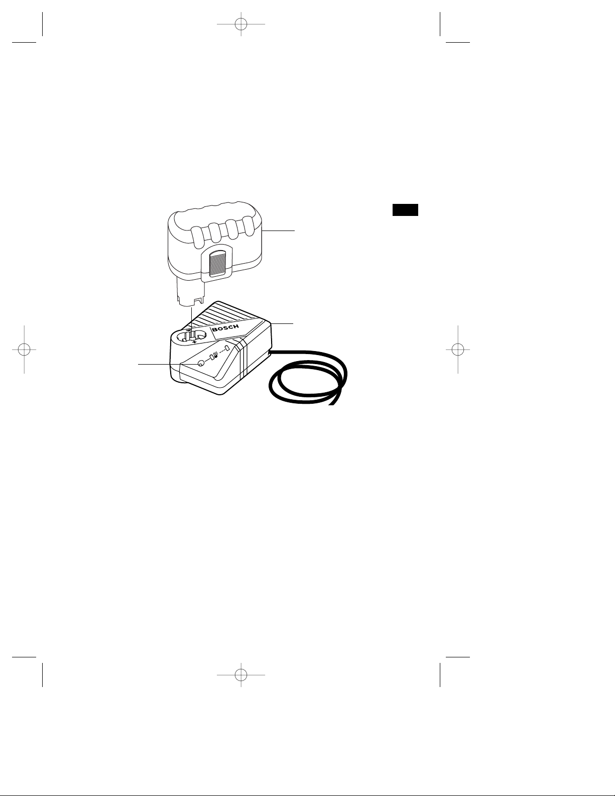
CHARGING BATTERY PACK (1 HOUR CHARGER)
INDICATOR
LIGHT
CHARGER
BATTERY PACK
FIG. 15
IMPORTANT CHARGING NOTES
1. The battery pack accepts only about 80%
of its maximum capacity with its first few
charge cycles. However, after the first few
charge cycles, the battery will charge to full
capacity.
2. The charger was designed to fast charge
the battery only when the battery
temperature is between 40˚F (4˚C) and 105˚F
(41˚C).
3. A substantial drop in operating time per
charge may mean that the battery pack is
nearing the end of its life and should be
replaced.
4. If you anticipate long periods (i.e. a month
or more) of non-use of your tool, it is best to
run your tool down until it is fully discharged
before storing your battery pack. After a long
period of storage, the capacity at first
recharge will be lower. Normal capacity will be
restored in two or three charge/discharge
cycles. Remember to unplug charger during
storage period.
5. If battery does not charge properly:
a. Check for voltage at outlet by
plugging in some other electrical device.
b. Check to see if outlet is connected to
a light switch which turns power “off” when
lights are turned off.
c. Check battery pack terminals for dirt.
Clean with cotton swab and alcohol if
necessary.
d. If you still do not get proper charging,
take or send tool, battery pack and charger
to your local Bosch Service Center. See
“Tools, Electric” in the Yellow Pages for
names and addresses.
Note: Use of chargers or battery packs not
sold by Bosch may void the warranty.
Plug charger cord into your standard power
outlet, then insert battery pack into
charger.The charger’s green indicator will
begin to “BLINK”. This indicates that the
battery is receiving a fast charge. Fastcharging will automatically stop when the
battery pack is fully charged.
When the indicator light stops “BLINKING”
(and becomes a steady green light) fast
charging is complete.
When you begin the charging process of the
battery pack, a steady green light could also
mean the battery pack is too hot or too cold.
The purpose of the light is to indicate that the
battery pack is fast-charging. It does not
indicate the exact point of full charge. The
light will stop blinking in less time if the
battery pack was not completely
discharged.
When the battery pack is fully charged,
unplug the charger (unless you're charging
another battery pack) and slip the battery
pack back into the tool handle (Fig.15).
BM 2610998757 11/01 11/2/01 3:32 PM Page 13
Page 14
-14-
Maintenance
(*= standard equipment)
(**= optional accessories)
* 1 hour charger
* rip fence
* 5-3/8" thin kerf 18 tooth carbide blade
** 5-3/8" thin kerf 24 tooth carbide blade
** 15 minute charger
** 15 foot “Airsweep” hose, attaches to most
vacuum cleaners
Service
NO USER SERVICEABLE
PARTS INSIDE. Preventive
maintenance performed by unauthorized
personnel may result in misplacing of
internal wires and components which
could cause serious hazard. We recom-
mend that all tool service be performed by a
Bosch Factory Service Center or Authorized
Bosch Service Station. SERVICEMEN:
Disconnect tool and/or charger from power
source before servicing.
BATTERIES
Be alert for battery packs that are nearing
their end of life. Battery packs typically last
from 500 to 1000 charges. If you notice
decreased tool performance or significantly
shorter running time between charges then it
is time to replace the battery pack. Failure
to do so can cause the tool to operate
improperly or damage the charger.
Long term battery storage should be in
the discharged state. Battery packs last
longer and re-charge better when they are
stored discharged. Remember to fully recharge battery packs before using after
prolonged storage.
TOOL LUBRICATION
Your Bosch tool has been properly
lubricated and is ready for use.
D.C. MOTORS
The motor in your tool has been engineered
for many hours of dependable service. To
maintain peak efficiency of the motor, we
recommend it be examined every six
months. Only a genuine Bosch replacement
motor specially designed for your tool
should be used.
BEARINGS
Bearings which become noisy (due to heavy
load or very abrasive material cutting) should
be replaced at once to avoid overheating and
motor failure.
Cleaning
To avoid accidents, always
disconnect the tool and/or
charger from the power supply before
cleaning. The tool may be cleaned most
effectively with compressed dry air. Always
wear safety goggles when cleaning tools
with compressed air.
Ventilation openings and switch levers must
be kept clean and free of foreign matter. Do
not attempt to clean by inserting pointed
objects through opening.
Certain cleaning agents and
solvents damage plastic
parts. Some of these are: gasoline, carbon
tetrachloride, chlorinated cleaning solvents,
ammonia and household detergents that
contain ammonia.
!
WARNING
!
WARNING
!
CAUTION
If an extension cord is
necessary, a cord with
adequate size conductors that is capable
of carrying the current necessary for your
tool must be used. This will prevent
excessive voltage drop, loss of power or
overheating. Grounded tools must use 3wire extension cords that have 3-prong
plugs and receptacles.
NOTE: The smaller the gauge number, the
heavier the cord.
RECOMMENDED SIZES OF EXTENSION
CORDS120 VOLT ALTERNATING CURRENT
Tool’s
Ampere
Rating
Cord Size in A.W.G.
Wire Sizes in mm
2
3-6
6-8
8-10
10-12
12-16
18 16 16 14 .75 .75 1.5 2.5
18 16 14 12 .75 1.0 2.5 4.0
18 16 14 12 .75 1.0 2.5 4.0
16 16 14 12 1.0 2.5 4.0 —
14 12 — — — — — —
25 50 100 150 15 30 60 120
Cord Length in Feet Cord Length in Meters
!
WARNING
Accessories
BM 2610998757 11/01 11/2/01 3:32 PM Page 14
Page 15

-15-
Vous devez lire et comprendre toutes les instructions. Le non-respect, même partiel,
des instructions ci-après entraîne un risque de choc életrique, d'incendie et/ou de
blessures graves.
CONSERVEZ CES INSTRUCTIONS
AVERTISSEMENT
!
Aire de travail
Veillez à ce que l'aire de travail soit propre et bien
éclairée. Le désordre et le manque de lumière
favorisent les accidents.
N'utilisez pas d'outils électriques dans une
atmosphère explosive, par exemple enprésence de
liquides, de gaz ou de poussières inflammables. Les
outils électriques créent des étincelles qui pourraient
enflammer les poussières ou les vapeurs.
Tenez à distance les curieux, les enfants et les
visiteurs pendant que vous travaillezavec un outil
électrique. Ils pourraient vous distraire et vous faire
faire une fausse manoeuvre.
Sécurité électrique
N'abusez pas du cordon. Ne transportez jamais
l'outil par le cordon. Tenez le cordon à l'écart de la
chaleur, de l'huile, des arêtes vives ou des pièces
mobiles. Remplacez les cordons endommagés
immédiatement. Les cordons endommagés peuvent
provoquer un incendie.
Un outil à pile avec piles incorporées ou bloc-pile
distinct doit être rechargé uniquement avec le
chargeur indiqué pour la pile. Un chargeur qui peut
être adéquat pour un type de pile peut créer un risque
d'incendie lorsqu'il est utilisé avec une autre pile.
Utiliser un outil à pile uniquement avec le bloc-pile
désigné spécifiquement. L'emploi de toute autre pile
peut créer un risque d'incendie.
Sécurité des personnes
Restez alerte, concentrez-vous sur votre travail et
faites preuve de jugement. N'utilisez pas un outil
électrique si vous êtes fatigué ou sous l'influence de
drogues, d'alcool ou de médicaments. Un instant
d'inattention suffit pour entraîner des blessures graves.
Habillez-vous convenablement. Ne portez ni
vêtements flottants ni bijoux. Confinez les cheveux
longs. N'approchez jamais les cheveux, les
vêtements ou les gants des pièces en mouvement.
Des vêtements flottants, des bijoux ou des cheveux
longs risquent d'être happés par des pièces en
mouvement. Gardez les poignées sèches, propres et
exemptes d'huile et de graisse.
Évitez la mise en marche accidentelle. Assurezvous que l'interrupteur est en position de blocage
ou d'arrêt avant d'insérer le bloc-pile. Il est
dangereux de transporter l'outil avec le doigt sur
l'interrupteur ou d'insérer le bloc-pile dans un outil
alors que l'interrupteur est en position de marche.
Enlevez les clés de réglage ou de serrage avant de
démarrer l'outil. Une clé laissée dans une pièce
tournante de l'outil peut provoquer des blessures.
Ne vous penchez pas trop en avant. Maintenez un bon
appui et restez en équilibre entout temps. Un bonne
stabilité vous permet de mieux réagir à une situation
inattendue.
Utilisez des accessoires de sécurité. Portez toujours
des lunettes ou une visière. Selon les conditions,
portez aussi un masque antipoussière, des bottes de
sécurité antidérapantes, un casque protecteur et/ou un
appareil antibruit.
Utilisation et entretien des outils
Immobilisez le matériau sur une surface stable au
moyen de brides ou de toute autre façon adéquate. Le
fait de tenir la pièce avec la main ou contre votre corps
offre une stabilité insuffisante et peut amener un
dérapage de l'outil.
Ne forcez pas l'outil. Utilisez l'outil approprié à la
tâche. L'outil correct fonctionne mieux et de façon plus
sécuritaire. Respectez aussi la vitesse de travail qui lui
est propre.
N'utilisez pas l'outil si l'interrupteur ne le met pas
en marche ou à l'arrêt. Un outil qui ne peut être
contrôlé par l'interrupteur est dangereux et doit être
réparé.
Débranchez le bloc-pile de l'outil ou mettez
l'interrupteur en position de blocage ou d'arrêt
avant d'effectuer tout réglage, de changer les
accessoires ou de remiser l'outil. Ces mesures de
sécurité préventives réduisent le risque d'une mise en
marche accidentelle de l'outil.
Rangez les outils hors de la portée des enfants et
d'autres personnes inexpérimentées. Les outils sont
dangereux dans les mains d'utilisateurs novices.
Lorsque le bloc-pile n'est pas en usage, tenez-le à
l'écart d'autres objets métalliques tels que
trombones, pièces de monnaie, clés, clous, vis ou
autres petits objets métalliques susceptibles
d'établir une connexion d'une borne à une autre. Le
court-circuitage des bornes de batterie ensemble peut
causer des étincelles, des brûlures ou un incendie.
Consignes générales de sécurité
pour tous les outils à piles
BM 2610998757 11/01 11/2/01 3:32 PM Page 15
Page 16

-16-
Prenez soin de bien entretenir les outils. Les outils de
coupe doivent être toujours bien affûtés et propres.
Des outils bien entretenus, dont les arêtes sont bien
tranchantes, sont moins susceptibles de coincer et plus
faciles à diriger.
Soyez attentif à tout désalignement ou coincement
des pièces en mouvement, à tout bris ou à toute autre
condition préjudiciable au bon fonctionnement de
l'outil. Si vous constatez qu'un outil est endommagé,
faites-le réparer avant de vous en servir. De
nombreux accidents sont causés par des outils en
mauvais état.
N'utilisez que des accessoires que le fabricant
recommande pour votre modèle d'outil. Certains
accessoires peuvent convenir à un outil, mais être
dangereux avec un autre.
Réparation
La réparation des outils électriques doit être confiée
à un réparateur qualifié. L'entretien ou la réparation
d'un outil électrique par un amateur peut avoir des
conséquences graves.
Pour la réparation d'un outil, n'employez que des
pièces de rechange d'origine. Suivez les directives
données à la section « Réparation » de ce manuel.
L'emploi de pièces non autorisées ou le non-respect
des instructions d'entretien peut créer un risque de
choc électrique ou de blessures.
Tenez les mains à l'écart de l'aire
de coupe et de la lame. Gardez
votre deuxième main sur la poignée auxiliaire ou le
carter du moteur. Si les deux mains tiennent la scie,
elles ne peuvent être coupées par la lame. Tenez la scie
fermement pour prévenir une perte de contrôle. Les
figures de ce manuel illustrent le support manuel
typique de la scie. Ne JAMAIS placez votre main
derrière la lame de la scie car le rebond pourrait faire
sauter la scie vers l'arrière par-dessus votre main.
Gardez votre corps positionné d'un côté ou de l'autre
de la lame de scie, mais non dans le prolongement
de la lame de scie. Le REBOND pourrait faire sauter la
scie vers l'arrière. (Voir « Causes et prévention, par
l'opérateur, du rebond »).
N'introduisez pas la main sous l'ouvrage. Le garde ne
peut vous protéger de la lame sous l'ouvrage. Ne tentez
pas d'enlever des matériaux coupés lorsque la lame est
en mouvement.
Vérifiez le garde inférieur pour vous assurer qu'il
ferme adéquatement avant chaque usage. N'utilisez
pas la scie si le garde inférieur ne bouge pas
librement et ne ferme pas instantanément. Ne pincez
ou ne fixez jamais le garde inférieur en position
ouverte. Si la scie tombe par mégarde, le garde
inférieur peut être plié. Levez le garde inférieur
uniquement à l'aide de la levier de levage du garde
inférieur, et assurez-vous qu'il bouge librement et ne
vient pas en contact avec la lame ou aucune autre pièce,
sous tous les angles et profondeurs de coupe.
Vérifiez le fonctionnement du ressort du rappel du
garde inférieur. Si le garde et le ressort ne
fonctionnent pas adéquatement, ils doivent être
réparés avant usage. Le garde inférieur peut
fonctionner paresseusement en raison de pièces
abîmées, de dépôts gommeux ou d'une accumulation
de débris. Débranchez le bloc-pile de l'outil. À
intervalles périodiques, déposez la lame, nettoyez les
gardes supérieur et inférieur et la région du moyeu à
l'aide de kérosène et essuyez pour sécher, ou nettoyez
en soufflant de l'air comprimé.
Le garde inférieur doit être rétracté manuellement
uniquement pour des coupes spéciales telles que les
« coupes en poche » et les « coupes combinées ».
Levez le garde inférieur à l'aide de la levier de levage
du garde inférieur. Le garde inférieur doit être relâché
dès que la lame pénètre dans l'ouvrage. Pour toutes les
autres opérations de sciage, le garde inférieur doit
fonctionner automatiquement.
Assurez-vous toujours que le garde inférieur couvre la
lame avant de déposer la scie sur l'établi ou le
plancher. Une lame non protégée, qui continue à
marcher par inertie, fera reculer la scie, coupant ainsi
tout ce qui est sur son chemin. Sachez le temps qu'il
faut pour que la lame s'arrête après relâchement de
l'interrupteur.
Ne tenez JAMAIS la pièce à couper dans vos mains ou
sur vos jambes. Il importe de supporter l'ouvrage
adéquatement afin de minimiser l'exposition corporelle,
le grippage de lame ou la perte de contrôle.
Consignes de sécurité pour scies circulaires
DANGER
!
BM 2610998757 11/01 11/2/01 3:32 PM Page 16
Page 17

Tenez l'outil par les surfaces isolées de préhension
en effectuant une opération au cours de laquelle
l'outil de coupe peut venir en contact avec des fils
dissimulés ou son propre cordon. Le contact avec un
fil sous tension rendra également les parties métalliques
exposées de l'outil sous tension et causera des chocs à
l'opérateur.
En refendant, utilisez toujours un guide de refente ou
une règle. Ceci améliore l'exactitude de la coupe et
réduit les possibilités de grippage de la lame.
Utilisez toujours des lames avec trous d'arbre de la
dimension et de la forme appropriées (en diamant par
rapport à rondes). Les lames qui ne se marient pas
avec le système de montage de la scie ne tourneront
pas rond. Il en résultera une perte de contrôle et un
mauvais fonctionnement du vari-torque.
N'utilisez jamais des rondelles ou boulons de lame
abîmés ou incorrects. Les rondelles et les boulons de
lame ont été conçus spécialement pour votre scie, pour
une performance optimale et pour un fonctionnement
des plus sûrs. Les rondelles de lame et le boulon sur
votre scie ont été conçus de manière à travailler comme
« EMBRAYAGE À COUPLE VARIABLE ». Comprenez le
fonctionnement et les réglages de l'EMBRAYAGE À
COUPLE VARIABLE car le réglage approprié de
l'EMBRAYAGE, combiné au maniement ferme de la scie,
vous permettra de contrôler le REBOND.
Ne faites pas fonctionner la scie tout en la portant à
votre côté. Le garde inférieur peut s'ouvrir au contact
avec vos vêtements. Un contact accidentel avec la lame
de scie en rotation pourrait provoquer des blessures
graves.
Suivant l'usage, l'interrupteur peut ne pas durer aussi
longtemps que la scie. Si l'interrupteur fait défaut en
position d'arrêt, la scie peut ne pas se mettre en
marche. S'il devient défectueux pendant que la scie
est en marche, la scie peut ne pas s'arrêter. Dans les
deux cas, enlevez immédiatement le bloc-pile de la scie
et n’utilisez pas la scie avant qu’elle ait été réparée.
Cette scie circulaire ne doit pas être montée sur une
table et convertie en scie de table. Les scies
circulaires ne sont pas conçues ni destinées à être
utilisées comme scies de table.
CAUSES ET PRÉVENTION, PAR L'OPÉRATEUR,
DU REBOND :
Le rebond est une réaction soudaine à une lame de scie
pincée, grippée ou mal alignée, amenant ainsi la scie
non contrôlée à lever et ressortir de l'ouvrage en
direction de l'opérateur.
Lorsque la lame est pincée ou grippée fermement par le
trait de scie qui se referme, la lame bloque et la réaction
du moteur ramène rapidement l'outil en direction de
l'opérateur.
Si la lame devient tordue ou mal alignée dans la coupe,
les dents du bord arrière de la lame peuvent s'enfoncer
dans la surface supérieure du bois, amenant ainsi la
lame à sortir du trait de scie et à revenir vers
l'opérateur.
Le rebond est le résultat d'une utilisation erronée de
l'outil et/ou de méthodes ou de conditions de
fonctionnement incorrectes, et on peut l'éviter en
prenant les précautions appropriées, comme indiqué ciaprès :
Maintenez une prise ferme avec les deux mains sur la
scie et positionnez votre corps et votre bras de
manière à résister aux forces de REBOND. L'opérateur
peut contrôler les forces de rebond si les précautions
appropriées sont prises.
Lorsque la lame grippe ou lorsqu'une coupe est
interrompue pour quelque motif que ce soit, relâchez
la gâchette et tenez la scie sans bouger dans
l'ouvrage jusqu'à ce que la lame s'arrête
complètement. Ne tentez jamais de retirer la scie de
l'ouvrage ou de tirer la scie vers l'arrière pendant que
la lame est en mouvement, ce qui pourrait provoquer
un REBOND. Recherchez la cause du grippage de lame
et prenez les mesures nécessaires pour le corriger. Le
bois mouillé, le bois vert ou le bois traité par pression
nécessitent une attention spéciale durant la coupe pour
prévenir le REBOND. Évitez de couper les clous.
Recherchez et enlevez tous les clous du bois avant de
couper.
Lorsque vous remettez une scie en marche dans un
ouvrage, centrez la lame de scie dans le trait de scie
et assurez-vous que les dents de scie ne sont pas
engagées dans l'ouvrage. Si la lame de scie grippe, elle
peut remonter ou REBONDIR depuis l'ouvrage lorsque
la scie est remise en marche.
Supportez les gros panneaux pour minimiser le risque
de pincement de lame et de REBOND. Les gros
panneaux ont tendance à s'affaisser sous leur propre
poids. Des supports doivent être placés sous le panneau
des deux côtés, près de la ligne de coupe et près du
bord du panneau. Voir « Coupe de gros panneaux»
dans ce manuel.
-17-
REBOND
BM 2610998757 11/01 11/2/01 3:32 PM Page 17
Page 18

Chargeur de pile
Avant d'utiliser le chargeur de pile, lisez toutes les
consignes et tous les marquages d'avertissement
sur (1) le chargeur de pile, (2) le bloc-pile et (3) le
produit utilisant la pile.
N'utilisez que le chargeur qui accompagnait votre
produit ou remplacement direct, comme indiqué
dans le catalogue ou ce manuel. Ne substituez aucun
autre chargeur. N’utiliser que les chargeurs approuvés
par Bosch avec votre produit. Voir Description
fonctionnelle et Spécifications.
Ne désassemblez pas le chargeur et ne l'utilisez
pas s'il a reçu un choc violent, s'il est tombé ou s'il
a été endommagé par ailleurs. Remplacez
immédiatement les cordons ou les fiches abîmés.
Un remontage incorrect ou des dommages peuvent
provoquer un incendie ou des secousses électriques.
Ne rechargez pas la pile dans un environnement
mouillé ou humide. N'exposez pas le chargeur à la
pluie ou la neige. Si le boîtier de la pile est fissuré
ou endommagé par ailleurs, ne l'insérez pas dans
le chargeur. Il pourrait y avoir un incendie ou un
court-circuit de pile.
Ne charger que des piles rechargeables approuvées
par Bosch. Voir Description fonctionnelle et
Spécifications. Les autres types de piles peuvent
éclater causant ainsi des blessures et des dommages.
Chargez le bloc-pile à des températures de plus de
4 degrés C (+40°F) et de moins de 41 degrés C
(+105°F). Conservez l'outil et le bloc-pile à des
endroits où la température ne descend pas sous 4
degrés C ou ne dépasse pas 49 degrés C. Laissez le
bloc-pile revenir à la température ambiante avant
de tenter de charger. Ceci est important pour
prévenir des dommages considérables aux éléments
des piles.
Il peut y avoir une fuite de pile dans des conditions
extrêmes d'utilisation ou de température. Évitez
tout contact avec la peau et les yeux. Le liquide de
pile est caustique et pourrait causer des brûlures
chimiques aux tissus. Si le liquide vient en contact
avec la peau, lavez rapidement à l'eau savonneuse,
puis au jus de citron ou au vinaigre. Si le liquide vient
en contact avec les yeux, rincez-les à l'eau pendant au
moins 10 minutes et sollicitez des soins médicaux.
Posez le chargeur sur une surface plate
inflammable et à distance de matériaux
inflammables lorsqu’on recharge un bloc-piles. Le
chargeur et le bloc-piles s’échauffent pendant la
charge. Le coussinet de mousse souple et autres
surfaces isolantes empêchent la circulation normale
de l’air, ce qui peut provoquer une surchauffe du
chargeur et du bloc-piles. S’il y a dégagement de
fumée ou si le boîtier fond, débranchez le chargeur
immédiatement et n’utilisez ni le chargeur, ni le blocpiles.
L'utilisation d'un accessoire non recommandé ni
vendu par Bosch peut causer des risques
d'incendie, de chocs électriques ou de lésions
corporelles.
N'utilisez pas une lame émoussée ou abîmée. Les
lames non affûtées ou réglées de façon inappropriée
produisent un trait de scie étroit, ce qui cause une
friction excessive, un grippage de lame et un REBOND.
Les boutons de blocage de réglage de biseau et de
profondeur de lame doivent être serrés et fermes
avant de pratiquer la coupe. Un déplacement du
réglage de lame durant la coupe peut causer un
grippage et un REBOND. L'utilisation de la scie avec un
réglage excessif de profondeur de coupe accroît la
charge sur l'outil et la sensibilité à la torsion de la lame
dans le trait de scie. Elle accroît également la surface de
lame disponible pour pincement dans des conditions de
fermeture du trait de scie.
Redoubler de prudence en pratiquant une « coupe de
poche » dans des murs existants ou autres parties
aveugles. La lame faisant saillie peut couper des objets
qui peuvent causer un REBOND.
Les travaux à la machine
tel que ponçage, sciage,
meulage, perçage et autres travaux du bâtiment
peuvent créer des poussières contenant des produits
chimiques qui sont des causes reconnues de cancer,
de malformation congénitale ou d’autres problèmes
reproductifs. Ces produits chimiques sont, par
exemple :
• Le plomb provenant des peintures à base de plomb,
• Les cristaux de silices provenant des briques et du
ciment et d’autres produits de maçonnerie, et
• L’arsenic et le chrome provenant des bois traités
chimiquement
Le niveau de risque dû à cette exposition varie avec la
fréquence de ces types de travaux. Pour réduire
l’exposition à ces produits chimiques, il faut travailler
dans un lieu bien ventilé et porter un équipement de
sécurité approprié tel que certains masques à poussière
conçus spécialement pour filtrer les particules
microscopiques.
-18-
AVERTISSEMENT
!
BM 2610998757 11/01 11/2/01 3:32 PM Page 18
Page 19

-19-
Lorsque les piles ne sont
pas dans l’outil ou le
chargeur, gardez-les à l’écart d’objets métalliques.
Ainsi, pour éviter un court-circuitage des bornes, NE
PLACEZ PAS les piles dans la boîte à outils ou dans la
poche avec des clous, des vis, des clés, etc. Ceci peut
provoquer un incendie ou des blessures.
NE METTEZ PAS LES PILES AU FEU ET NE LES
EXPOSEZ PAS À UNE CHALEUR ÉLEVÉE. Elles peuvent
exploser.
AVERTISSEMENT
!
Entretien des piles
Ne tentez pas de
désassembler le bloc-piles
ou d’enlever tout composant faisant saillie des
bornes de piles, ce qui peut provoquer un incendie ou
des blessures. Avant la mise au rebut, protégez les
bornes exposées à l’aide d’un ruban isolant épais pour
prévenir le court-circuitage.
PILES NICKEL-CADMIUM
Si le produit est équipé d'une pile nickel-cadmium, la
pile doit être ramassée, recyclée ou mise au rebut
d'une manière qui ne soit pas nocive pour
l'environnement.
“Le sceau RBRC de recyclage des
piles, homologué par l’EPA
(Agence pour la protection de
l’environnement des États-Unis),
qui se trouve sur les piles au
nickel-cadmium (Ni-Cd) indique
que S-B Power Tool Company
participe volontairement à un programme industriel de
ramassage et de recyclage de ces piles au terme de
leur vie utile, pourvu qu’elles soient mises hors
service aux États-Unis ou au Canada. Le programme
du RBRC offre une alternative pratique à la mise des
piles au Ni-Cd usées au rebut ou au ramassage
d’ordures municipal, ce qui pourrait être interdit dans
votre région.
Veuillez appeler le 1-800-8-BATTERY pour obtenir de
plus amples renseignements sur le recyclage des piles
au Ni-Cd et sur les restrictions ou interdictions de
mise au rebut qui s’appliquent à votre région ou
renvoyez vos piles à un Centre de Service
Skil/Bosch/Dremel pour recyclage. La participation de
S-B Power Tool Company à ce programme s'insère
dans le contexte de notre engagement à préserver
notre environnement et à conserver nos ressources
naturelles.”
PILES NICKEL-HYDRURE DE MÉTAL
Si le produit est équipé d'une pile nickel-hydrure de
métal, la pile peut être mise au rebut dans un flux de
déchets solides municipaux.
AVERTISSEMENT
!
Mise au rebut des piles
BM 2610998757 11/01 11/2/01 3:32 PM Page 19
Page 20

-20-
Symboles
Important : Certains des symboles suivants peuvent être utilisés sur votre outil. Veuillez les étudier et apprendre
leur signification. Une interprétation appropriée de ces symboles vous permettra d'utiliser l'outil de façon plus
efficace et plus sûre.
Symbole Nom Désignation/Explication
V Volts Tension (potentielle)
A Ampères Courant
Hz Hertz Fréquence (cycles par seconde)
W Watt Puissance
kg Kilogrammes Poids
min Minutes Temps
s Secondes Temps
Diamètre Taille des mèches de perceuse, meules,
etc.
n
0
Vitesse à vide Vitesse de rotation, à vide
.../min Tours ou mouvement alternatif par Tours, coups, vitesse en surface, orbites,
minute etc., par minute,
0 Position d'arrêt Vitesse zéro, couple zéro ...
1, 2, 3, ... Réglages du sélecteur Réglages de vitesse, de couple ou de
l, ll, lll, ... position. Un nombre plus élevé signifie
une vitesse plus grande.
Sélecteur variable à l'infini avec arrêt La vitesse augmente depuis le réglage 0
Flèche Action dans la direction de la flèche
Courant alternatif Type ou caractéristique du courant
Courant continu Type ou caractéristique du courant
Courant alternatif Type ou caractéristique du courant
ou continu
Construction classe II Désigne des outils construits avec double
isolation
Borne de terre borne de mise à la terre
Symbole d'avertissement Alerte l'utilisateur aux messages
d'avertissement.
Sceau Ni-Cad RBRCmc Désigne le programme de recyclage des piles
Ni-Cad.
0
Ce symbole signifie que cet
outil est approuvé par
Underwriters Laboratories.
Ce symbole signifie que cet
outil est approuvé par
l'Association canadienne de
normalisation.
Ce symbole signifie que
cet outil est approuvé
conformément aux normes
canadiennes par Underwriters
Laboratories.
Ce symbole
signifie que
cet outil se
conforme aux
normes
mexicaines
NOM.
Ce symbole signifie que cet outil
est approuvé par Underwriters
Laboratories et qu’il a été
homologué selon les normes
canadiennes par Underwriters
Laboratories.
BM 2610998757 11/01 11/2/01 3:32 PM Page 20
Page 21

-21-
Description fonctionnelle et spécifications
Outil Capacités maximales
Numéro de modèle 1659 1661 Lame 137 mm
Tension nominale 18 V 14,4 V Profondeur de coupe à 90° 41 mm
Régime à vide n0 3 600/min n0 3 600/min Profondeur de coupe à 45° 32 mm
Temps de Charge 1 hr 1 hr
Chargeur BC003,4,6 & BC016 BC001-6 & BC016 ATTENTION : Utilisez uniquement des
Bloc piles BAT025 BAT040 lames à voie étroite conçues pour les
Tension nominale 120 V 60 Hz 120 V 60 Hz scies circulaires sans fil.
Intensité nominale 2,5 A 1,9 A
Le chargeur BC006 nécessite une puissance d’alimentation de 12 V CC.
NOTE : N’UTILISER QUE LES CHARGEURS REPERTORIES CI-DESSUS
En rechange, nous vous conseillons d’utiliser les lames pour scies circulaires sans fil Bosch. Leur voie étroite et
la conception de leurs dents permettent d’obtenir de meilleures vitesse et qualité de sciage tout en réduisant
l’usure de la pile. Si vous utilisez des lames standards, la performance de la scie sera nettement dégradée et les
piles s’useront plus vite.
Débranchez le bloc-pile de l'outil ou placez l'interrupteur à la position de blocage
ou d'arrêt avant d'effectuer tout assemblage ou réglage ou de changer les
accessoires. Ces mesures de sécurité préventives réduisent le risque d'une mise en marche accidentelle de
l'outil.
AVERTISSEMENT
!
SEMELLE
LEVIER DE
LEVAGE DU
GARDE INFÉRIEUR
POIGNÉE
AUXILIAIRE
BOUTON DE
REGLAGE DU
BISEAU
SECTEUR GRADUÉ
DE BISEAU
COUVERCLE DE L'ORIFICE
POUSSIÈRES
BOUTON DE
RÉGLAGE DE LA
PROFONDEUR
Scie circulaire
sans fil
GARDE SUPÉRIEUR
GARDE
INFÉRIEUR
BOUTON DE
VERROUILLAGE
FIG. 1
TOUCHES DE
DÉVERROUILLAGE
DES PILES
BLOC-PILES
INTERRUPTEUR
DE SÛRETÉ
GÂCHETTE
CLÉ ET CASE DE REMISAGE
FLÈCHE DE FIN DE COUPE
FLÈCHE DE DÉBUT DE COUPE
PRISES D’AIR
BM 2610998757 11/01 11/2/01 3:32 PM Page 21
Page 22

MONTAGE DE LA LAME
Débranchez le bloc-pile de
l'outil ou placez
l'interrupteur à la position de blocage ou d'arrêt
avant d'effectuer tout assemblage ou réglage ou de
changer les accessoires. Ces mesures de sécurité
préventives réduisent le risque d'une mise en marche
accidentelle de l'outil.
1. Tournez le GOUJON DE LAME à l'aide de la clé
fournie en sens horaire et retirez le GOUJON DE LAME
et la RONDELLE EXTÉRIEURE (Fig. 2). Si l'arbre bouge
en tentant de desserrer le goujon de lame, appuyez sur
le bouton de blocage.
2. Faites remonter le garde inférieur de la lame en le
laissant coulisser totalement à l’intérieur du capot.
Profitez-en pour vérifier l’état et le fonctionnement du
RESSORT DU GARDE INFÉRIEUR.
3. Assurez-vous que les dents de la scie et la flèche sur
la lame sont dirigées dans le même sens que la flèche
figurant sur le garde inférieur de la lame.
4. Glissez la lame dans la fente de la semelle et placez-la
contre la RONDELLE INTÉRIEURE de l’arbre. Assurezvous que le plus grand côté des rondelles INTÉRIEURE
et EXTÉRIEURE appuie carrément sur la lame.
5. Réinstallez la RONDELLE EXTÉRIEURE et serrez le
GOUJON DE LAME à la main. La face de la rondelle
extérieure de lame comporte des graduations sur son
pourtour qui vous aideront à adjuster adéquatement le
goujon de lame. Appuyez sur le bouton de blocage
pour bloquer l'arbre et À L’AIDE DE LA CLÉ FOURNIE,
SERREZ LE GOUJON DE LAME EN SENS ANTI-
HORAIRE D’UNE GRADUATION DE LA RONDELLE
EXTÉRIEURE DE LAME.
N’utilisez pas de clés plus longues car vous risqueriez de
trop serrer le goujon.
EMBRAYAGE « VARI-TORQUE »
L’embrayage est assuré par la friction de la RONDELLE
EXTÉRIEURE sur la LAME et il permet à l’arbre de
continuer à tourner si la lame éprouve une résistance
excessive. Si le GOUJON DE LA LAME est correctement
serré (tel qu’il est expliqué à l’étape 5 du chapitre intitulé
Montage de la lame), la lame glissera sur son arbre
quand elle éprouve une résistance excessive, ce qui
réduit le risque de REBOND.
Il est possible qu’un seul et même réglage ne convienne
pas à tous les matériaux. Si la lame patine trop, serrez le
goujon de lame d’une demi-graduation de plus. LE
SERRAGE EXCESSIF DU GOUJON DE LA LAME REND
LE DISPOSITIF DE DÉBRAYAGE ABSOLUMENT
INUTILE.
EXTRACTION DE POUSSIÈRE
Votre outil est équipé d'un adaptateur d'orifice
poussières pour extraction de la poussière et des
copeaux. Pour utiliser ce système, ouvrez le couvercle
de l’orifice de poussières et raccordez un flexible
d’aspiration (accessoire en option). Raccordez l’autre
extrémité du flexible sur un aspirateur d’atelier.
Pour empêcher toute
blessure corporelle, placez
toujours le flexible d’aspiration de manière à ce qu’il
n’interfère pas avec la garde inférieure ou le sciage
quel que soit le réglage.
-22-
Assemblage
AVERTISSEMENT
!
AVERTISSEMENT
!
FIG. 2
DESSERRER
SERRER
GOUJON DE
LAME
RESSORT DE
RAPPEL DU
GARDE
INFÉRIEUR
RONDELLE EXTÉRIEURE
Grand diamètre orienté
vers la lame
RONDELLE INTÉRIEURE
Grand diamètre orienté
vers la lame
LAME
GARDE
INFÉRIEUR
ARBRE DE
LA LAME
GARDE
SUPÉRIEUR
CLÉ
RONDELLE EXTÉRIEURE
GRADUATION
BM 2610998757 11/01 11/2/01 3:32 PM Page 22
Page 23

-23-
Consignes de fonctionnement
Débranchez le bloc-pile de l'outil. Desserrez le bouton
de réglage de profondeur situé à l'arrière du garde
supérieur. Maintenez la semelle en place d’une main et
levez ou baissez la scie par la poignée de l’autre main.
Serrez le bouton à la profondeur de coupe désirée.
Vérifiez si la profondeur est bien celle que vous désirez
(fig. 3).
Pour réduire le risque d’écaillage des bords de la pièce à
couper, la lame ne devrait pas dépasser de plus de la
longueur d’une dent au dos de la pièce (fig. 4).
INTERRUPTEUR DE SÛRETÉ
L’interrupteur de sûreté est conçu de manière à prévenir
les démarrages accidentels. Pour actionner l’interrupteur
de sûreté, appuyez sur le bouton de relâchement avec
botre pouce d’un côté ou de l’autre de la poignée afin de
déverrouiller, puis tirez la gâchette (fig. 5). Lorsque la
gâchette est relâchée, le bouton engage
automatiquement l’interrupteur de sûreté, et la gâchette
n’est plus en fonction (reportez-vous à « Interrupteur et
coupes générales » à la page 22).
VÉRIFICATION DE L’ANGLE DE COUPE 90°
Débranchez le bloc-pile de l'outil. Réglez la semelle à la
profondeur de coupe maximale. Desserrez le bouton de
réglage de la coupe en biseau, réglez-le à 0° sur le
secteur ; resserrez-le bouton et, à l’aide d’une équerre
verifiez si la lame forme exactement un angle de 90°
avec la surface plane du dessous de la semelle (fig. 6).
Si un réglage s'avère nécessaire, inclinez la semelle à
45°, serrez l'écrou à oreilles de réglage du biseau, et
pliez la « PATTE » à l'aide d'une clé réglable ou de
pinces (Fig. 7).
RÉGLAGE DE LA PROFONDEUR DE COUPE
0
2
1
FIG. 3
FIG. 4
POUR ÉVITER L’ÉCAILLAGE DU BOIS, LA LAME NE
COIT PAS DÉPASSER DE PLUS DE LA LONGUEUR
D’UNE DENT AU DOS DE LA PIÈVR
BOUTON DE
RÉGLAGE DE LA
PROFONDEUR
SUPPORT À PROFON-
DEUR GRADUÉE
CLÉ ET CASE DE
REMISAGE
90°
FIG. 5
FIG. 6
BOUTON DE RELÂCHEMENT
DE L’INTERRUPTEUR DE
SÛRETÉ
PATTE
BOUTON DE
REGLAGE DU
BISEAU
LAME
GÂCHETTE
SEMELLE
FIG. 7
BM 2610998757 11/01 11/2/01 3:32 PM Page 23
Page 24

-24-
GUIDE D’ALIGNEMENT
Dans le cas d’une coupe droite à 90°, guidez-vous sur le
côté droit de l’encoche dans la semelle. Pour les coupes
en biseau de 45°, guidez-vous plutôt sur le côté gauche
(fig. 9). L’encoche-guide vous procurera une ligne de
coupe plus ou moins exacte. Faites une coupe d’essai
dans une retaille pour en vérifier l’exactitude. Il est bon
de prendre une telle mesure en raison du vaste
assortiment de lames de toutes épaisseurs sur le
marché. Pour éviter autant que possible d’abîmer le bon
côté du matériau à couper, il est recommandé de tourner
ce côté vers le bas.
INTERRUPTEUR
Appuyez sur la gâchette pour mettre l’outil en marche ;
relâchez-la pour l’arrêter. La gâchette retourne
automatiquement à la position d’arrêt.
La scie devrait tourner à plein régime AVANT de
commencer à scier et elle ne devrait être arrêtée
qu’APRÈS avoir terminé la coupe. Pour prolonger la
durée utile de l’interrupteur, évitez de mettre le moteur
en marche et de l’arrêter en sciant.
FREIN
Quand on relâche la gâchette, le frein est actionné et
arrête rapidement la lame. Cette caractéristique est des
plus utiles lors de sciages à répétition.
COUPES RÉGULIERES
Tenez toujours la poignée de la scie d'une main et la
poignée auxiliaire ou le logement de l'autre main.
Assurez-vous que la semelle de la scie repose toujours
sur la portion de la surface de la pièce qui ne plonge pas.
Assurez-vous que vos
mains ne gênent pas le
mouvement de la garde inférieure.
Serrez-la fermement et actionnez l’interrupteur
énergiquement. Ne forcez jamais la scie outre mesure.
Exercez une pression modérée et soutenue.
Après avoir terminé une
coupe et relâché la
gâchette, souvenez-vous que la lame ralentit et qu’il
lui faut un certain temps pour s’arrêter complètement.
Évitez que la scie ne vienne frôler votre jambe ou votre
côté car, étant donné qu’il est rétractible, le garde
inférieur de la lame risquerait de s’agripper à vos
vêtements et d’exposer la lame. Sachez qu’une partie
de la lame est exposée en permanence à l’endroit où
finissent le capot et le garde inférieur de la lame.
Pour recommencer à scier, suivant un arrêt, appuyez sur
la gâchette et attendez que la lame ait atteint son régime
maximal avant de rentrer lentement dans la pièce.
Lors de coupes en travers, les fibres du bois ont
tendance à se déchiqueter et à se soulever. Vous pouvez
minimiser le problème en avançant lentement la scie.
Pour réaliser une coupe nette, il est recommandé
d’utiliser une lame pour coupe en travers ou à onglets.
AVERTISSEMENT
!
AVERTISSEMENT
!
RÉGLAGE DE LA COUPE EN BISEAU
Débranchez le bloc-pile de l'outil. L’angle formé par la
lame par rapport à la semelle peut être réglé jusqu’à 50°
en desserrant le bouton de réglage de biseau à l’avant de
la scie. Réglez le bouton à l’angle désiré sur le secteur
gradué. Serrez ensuite le bouton de réglage de biseau
(fig. 8). En raison de l’engagement d’une plus grande
surface de la lame dans la pièce et la stabilité réduite de
la semelle, la lame risque de gripper. Suivez la ligne de
coupe, la semelle de la scie bien d’aplomb sur la pièce.
FIG. 9
COUPE EN
BISEAU DE
45°
COUPE VERTICALE
À 90°
FIG. 8
BOUTON DE
REGLAGE DU
BISEAU
SECTEUR GRADUÉ
BM 2610998757 11/01 11/2/01 3:32 PM Page 24
Page 25

-25-
COUPES EN GUICHET
Débranchez le bloc-pile de l'outil avant de procéder
aux réglages. Réglez la lame à la profondeur
correspondant à l’épaisseur du matériau à tailler.
Inclinez la scie vers l’avant en alignant l’encoche-guide
sur la ligne de coupe. Relevez le garde inférieur de la
lame, au moyen du levier de levage, et tenez la scie par
ses poignées avant et arrière (fig. 10).
La lame touchant presque à la pièce à tailler, mettez le
moteur en marche. Abaissez graduellement l’arrière de la
scie en utilisant l’extrémité avant de la semelle comme
point d’appui. AVERTISSEMENT : Aussitôt que la lame
commence à trancher le matériau, relâchez le garde
inférieur immédiatement. Dès que la semelle repose
bien à plat sur la surface que vous coupez, continuez la
coupe en poussant la scie vers l’avant jusqu’à la fin de la
ligne. AVERTISSEMENT : Attendez l’arrêt complet de
la lame avant de retirer la scie du trait que vous venez
de tailler dans le matériau. De même, ne ramenez
jamais la scie vers l’arrière, car la lame peut sortir du
matériau risquant de provoquer un REBOND. Soulevez
la scie et tournez-la en sens opposé pour achever
normalement la coupe dans l’autre sens. Si les coins de
votre coupe en guichet ne sont pas complètement taillés,
finissez-les à la scie sauteuse ou à l’égoïne.
COUPE DE GRANDES FEUILLES
Les grandes feuilles et les longs panneaux fléchissent ou
plient, selon la façon dont ils sont soutenus. Si vous
essayez de les couper sans les avoir mise au niveau et
soutenus par des supports au préalable, la lame aura
tendance à gripper provoquant des REBONDS et la
surcharge du moteur (fig. 11).
Placez le panneau ou la planche sur des supports situés
à proximité de la ligne de coupe, comme l’indique la fig.
12. Assurez-vous que la profondeur de coupe est réglée
de manière à ce que la lame ne traverse que la feuille ou
la planche à couper, sans faire d’entailles dans la table de
travail ou l’établi. Les deux-par-quatre utilisés pour
soulever et soutenir la pièce devraient reposer à plat
entre celle-ci et la table ou l’établi. Ne placez jamais les
deux-par-quatre sur leurs côtés plus étroits car cet
arrangement manquerait de stabilité. Si la feuille ou le
panneau est plus grand que la table ou l’établi, placez-le
sur des deux-par-quatre sur le plancher et assujettissezle.
COUPES DE REFENTE
La lame universelle fournie avec la scie convient tant
pour les coupes en travers que pour les coupes de
refente. La refente est la coupe en long, en sens du grain
du bois. Les coupes de refente sont faciles à exécuter
avec un guide de refente (fig. 13). Le guide de refente
(non livré avec la scie) est disponible moyennant
supplément de prix. Pour fixer le guide, insérez le guide
à travers les fentes pratiquées dans la semelle jusqu'à la
largeur désirée, comme illustré, et fixez à l'aide de
bouton.
UTILISATION D’UNE PLANCHE
COMME GUIDE DE REFENTE
Si vous devez exécuter une coupe de refente sur de
grandes feuilles, il est possible que le guide de refente ne
soit pas assez long pour permettre d’exécuter une coupe
à la largeur désirée. Dans ce cas, une planche bien droite
de 25 mm (1") d’épaisseur fixée à la feuille au moyen de
serres ou de clous peut servir de guide (fig. 14). Faites
glisser le côté droit de la semelle contre la planche.
FIG. 10
FIG. 11
FIG. 12
MAUVAISE
MANIÈRE
BONNE
MANIÈRE
SEMELLE
LEVIER DE
LEVAGE
DU GARDE
INFÉRIEUR
FIG. 13
FIG. 14
GUIDE DE
REFENTE
BOUTON
LARGEUR
DE COUPE
DÉSIRÉE
LIGNE DE
COUPE
DÉSIRÉE
PLANCHE DE
BOIS EN TANT
QUE GUIDE DE
REFENTE
BM 2610998757 11/01 11/2/01 3:32 PM Page 25
Page 26

-26-
CHARGE DU BLOC-PILE (CHARGEUR DE 1 HEURE)
TÉMON
LUMINEUX
CHARGEUR
BLOC-PILES
FIG. 15
REMARQUES IMPORTANTES CONCERNANT LA CHARGE
1. Lors des premiers cycles de charge, le bloc-piles
neuf n’absorbe que 80 % de sa capacité maximale.
Par la suite, cependant, les piles se chargeront à
pleine capacité.
2. De même, le chargeur n’est destiné qu’à la charge
rapide des bloc-piles dont la température se situe
entre 4°C (40°F) et 41°C (105°F).
3. Une diminution marquée de la réserve énergétique
entre les charges peut signaler l’épuisement du blocpiles et le besoin d’un remplacement.
4. Si vous prévoyez de longues périodes (à savoir, un
mois ou plus) de non-utilisation de votre outil, il est
préférable d'utiliser votre outil jusqu'à ce que sa pile
soit entièrement déchargée avant de remiser votre
bloc-pile. Après une longue période de remisage, la
capacité sera réduite à la première recharge. La
capacité normale sera rétablie en deux ou trois cycles
de charge/décharge. N'oubliez pas de débrancher le
chargeur durant la période de remisage.
5. Si le bloc-piles ne se charge pas normale-ment :
a. Vérifiez la présence de courant à la prise en y
branchant un autre appareil électrique.
b. Vérifiez si la prise n’est pas raccordée con-
jointement à un interrupteur qui servirait à éteindre
les lumières.
c. Vérifiez la propreté des bornes du bloc-piles.
Nettoyez-les au besoin avec un bâtonnet imbibé
d’alcool.
d. Si vous n’arrivez toujours pas à obtenir la
charge satisfaisante, confiez l’outil, le bloc-piles et le
chargeur à votre centre d’entretien Bosch habituel.
Voir les noms et adresses des centres d’entretien
sous la rubrique « Outils électriques» dans les pages
jaunes de l’annuaire de téléphone.
Remarque : L’usage de chargeurs ou de blocs-piles
autres que ceux vendus par Bosch peut annuler la
garantie.
Branchez le cordon du chargeur dans votre prise de
courant standard, insérez ensuite le bloc-pile dans le
chargeur. Le témoin vert du chargeur commencera à
CLIGNOTER, ce qui indique que la pile reçoit une
charge rapide. La charge rapide s'arrêtera
automatiquement lorsque le bloc-pile est à pleine
charge.
Le témoin CESSE DE CLIGNOTER (et s'allume en vert
continu) au terme de la charge rapide.
Lorsque vous commencez le processus de charge du
bloc-pile, un témoin vert continu pourrait également
signifier que le bloc-pile est trop chaud ou trop froid.
Le témoin a pour but d'indiquer que le bloc-pile est en
charge rapide. Il n'indique pas le point exact de pleine
charge. Le témoin cessera de clignoter en moins de
temp si le bloc-pile n'était pas entièrement déchargé.
Lorsque le bloc-pile est entièrement chargé,
débranchez le chargeur (à moins que vous ne chargiez
un autre bloc-pile) et réinsérez le bloc-pile dans la
poignée de l'outil (fig. 15).
BM 2610998757 11/01 11/2/01 3:32 PM Page 26
Page 27

-27-
(* = équipement de série)
(** = accessoires optionnels)
* Chargeur 1 heure
* Guide de refente
* Lame carbure de 137 mm à 18 dents à voie étroite
** Lame carbure de 137 mm po à 24 dents à voie
étroite
** Chargeur 15 minutes
** Flexible de 15 pieds « Airsweep », se raccorde sur
la plupart des aspirateurs
Entretien
IL N’EXISTE À
L’INTÉRIEUR AUCUNE
PIÈCE SUSCEPTIBLE D’ÊTRE ENTRETENUE PAR
L’UTILISATEUR. L’entretien préventif exécuté par
des personnes non autorisés peut entraîner un
positionnement erroné des composants et des fils
internes, ce qui peut présenter de graves dangers.
Nous recommandons de confier toute intervention
d’entretien sur l’outil à un centre de service-usine Bosch
ou à un centre de service après-vente Bosch agréé.
TECHNICIENS : Débranchez l’outil et/ou le chargeur de
la source de courant avant d’entretenir.
PILES
Faire attention aux blocs-piles qui approchent la fin
de leur vie. Les blocs-pile peuvent en général être
rechargés entre 500 et 1 000 fois. Si vous remarquez
une diminution dans les performances de votre outil ou
une durée de fonctionnement réduite de manière
significative entre charges, il est temps de remplacer le
bloc-piles. S’il n’est pas remplacé, il se peut qu’il
endommage le chargeur ou que l’outil fonctionne
incorrectement.
Les piles doivent être déchargées avant de les
entreposer pour une longue durée. Les blocs-piles
durent plus longtemps et se rechargent mieux quand ils
sont rangés déchargés. Rappelez-vous qu’il faut
complètement recharger les blocs-piles avant toute
utilisation survenant après un stockage prolongé.
GRAISSAGE DE L’OUTIL
Votre outil Bosch a été graissé de manière appropriée et
il est prêt à l’usage.
MOTEURS C.C.
Le moteur de votre outil a été conçu pour de
nombreuses heures d’utilisation fiable. Pour maintenir
l’efficacité maximale du moteur, nous recommandons
de l’examiner tous les six mois. Seul un moteur de
remplacement Bosch authentique, conçu spécialement
pour votre outil, doit être utilisé.
ROULEMENTS
Les roulements qui deviennent bruyants (en raison
d’une charge importante ou de la coupe de matériaux
très abrasifs) doivent être remplacés immédiatement
pour éviter la surchauffe et les défaillances du moteur.
Nettoyage
Pour éviter les accidents,
débranchez toujours l’outil
et/ou le chargeur de la source de courant avant de
nettoyer. La façon la plus efficace de nettoyer l’outil est
à l’aide d’air sec comprimé. Portez toujours des
lunettes de sécurité en nettoyant les outils à l’air
comprimé.
Gardez les prises d’air et les interrupteurs propres et
libres de débris. N’essayez pas de les nettoyer en
introduisant des objets pointus dans leurs ouvertures.
Certains produits de
nettoyage et dissolvants
dont la gazoline, le tétrachlorure de carbone, les
nettoyeurs chlorés, l’ammoniaque et les détergents
ménagers contenant de l’ammoniaque peuvent
abîmer les pièces en plastique.
Maintenance
MISE EN GARDE
!
AVERTISSEMENT
!
AVERTISSEMENT
!
Si un cordon de rallonge
s'avère nécessaire, vous
devez utiliser un cordon avec conducteurs de
dimension adéquate pouvant porter le courant
nécessaire à votre outil. Ceci préviendra une chute
excessive de tension, une perte de courant ou une
surchauffe. Les outils mis à la terre doivent utiliser des
cordons de rallonge trifilaires pourvus de fiches à trois
broches ainsi que des prises à trois broches.
REMARQUE : Plus le calibre est petit, plus le fil est gros.
DIMENSIONS DE RALLONGES RECOMMANDÉES
OUTILS 120 VOLTS COURANT ALTERNATIF
AVERTISSEMENT
!
Intensité
nominale
de l’outil
Longueur en pieds
Longueur en mètres
3-6
6-8
8-10
10-12
12-16
18 16 16 14 .75 .75 1.5 2.5
18 16 14 12 .75 1.0 2.5 4.0
18 16 14 12 .75 1.0 2.5 4.0
16 16 14 12 1.0 2.5 4.0 —
14 12 — — — — — —
25 50 100 150 15 30 60 120
Calibre A.W.G.
Calibre en mm
2
Accessoires
BM 2610998757 11/01 11/2/01 3:32 PM Page 27
Page 28

-28-
Lea y entienda todas las instrucciones. El incumplimiento de todas las instrucciones
indicadas a continuación puede dar lugar a sacudidas eléctricas, incendios y/o lesiones
personales graves.
CONSERVE ESTAS INSTRUCCIONES
Area de trabajo
Mantenga el área de trabajo limpia y bien iluminada.
Las mesas desordenadas y las áreas oscuras invitan a
que se produzcan accidentes.
No utilice herramientas mecánicas en atmósferas
explosivas, tales como las existentes en presencia de
líquidos, gases o polvos inflamables. Las
herramientas mecánicas generan chispas y éstas
pueden dar lugar a la ignición del polvo o los vapores.
Mantenga a las personas que se encuentren
presentes, a los niños y a los visitantes alejados al
utilizar una herramienta mecánica. Las distracciones
pueden hacer que usted pierda el control.
Seguridad eléctrica
No abuse del cordón. Nunca use el cordón para
llevar la herramienta. Mantenga el cordón alejado
del calor, el aceite, los bordes afilados o las piezas
móviles. Cambie los cordones dañados
inmediatamente. Los cordones dañados pueden
causar un incendio.
Una herramienta accionada por baterías que tenga
baterías integradas o un paquete de baterías
separado se debe recargar solamente con el
cargador especificado para la batería. Un cargador
que puede ser adecuado para un tipo de batería puede
crear un peligro de incendio cuando se usa con otra
batería.
Utilice la herramienta accionada por baterías
solamente con el paquete de baterías designado
específicamente. El uso de cualquier otra batería
puede crear un peligro de incendio.
Seguridad personal
Manténgase alerta, fíjese en lo que está haciendo y
use el sentido común cuando utilice una herramienta
mecánica. No use la herramienta cuando esté
cansado o se encuentre bajo la influencia de drogas,
alcohol o medicamentos. Un momento de distracción
al utilizar herramientas mecánicas puede dar lugar a
lesiones personales graves.
Vístase adecuadamente. No se ponga ropa holgada ni
joyas. Sujétese el pelo. Mantenga el pelo, la ropa y
los guantes alejados de las piezas móviles. La ropa
holgada, las joyas o el pelo largo pueden quedar
atrapados en las piezas móviles. Mantenga los mangos
secos, limpios y libres de aceite y grasa.
Evite el arranque accidental. Asegúrese de que el
interruptor esté en la posición fijada o de apagado
antes de introducir el paquete de baterías. Llevar
herramientas con el dedo en el interruptor o
introducir el paquete de baterías en una herramienta
con el interruptor en la posición de encendido invita a
que se produzcan accidentes.
Quite las llaves de ajuste o de tuerca antes de
encender la herramienta. Una llave de ajuste o de
tuerca que se deje puesta en una pieza giratoria de la
herramienta puede ocasionar lesiones personales.
No intente alcanzar demasiado lejos. Mantenga un
apoyo de los pies y un equilibrio adecuados en todo
momento. El apoyo de los pies y el equilibrio
adecuados permiten un mejor control de la herramienta
en situaciones inesperadas.
Utilice equipo de seguridad. Use siempre protección
de los ojos. Se debe utilizar una máscara antipolvo,
zapatos de seguridad antideslizantes, casco o
protección de los oídos según lo requieran las
condiciones.
Utilización y cuidado de las herramientas
Utilice abrazaderas u otro modo práctico de fijar y
soportar la pieza de trabajo a una plataforma estable.
La sujeción de la pieza de trabajo con la mano o contra
el cuerpo resulta inestable y puede ocasionar pérdida de
control.
No fuerce la herramienta. Use la herramienta
correcta para la aplicación que desea. La herramienta
correcta hará el trabajo mejor y con más seguridad a la
capacidad nominal para la que está diseñada.
No utilice esta herramienta si el interruptor no la
enciende o apaga. Una herramienta que no se puede
controlar con el interruptor es peligrosa y se debe
reparar.
Desconecte el paquete de baterías de la
herramienta o ponga el interruptor en la posición
fijada o de apagado antes de hacer cualquier
ajuste, cambiar accesorios o guardar la
herramienta. Dichas medidas preventivas de
seguridad reducen el riesgo de arrancar la
herramienta accidentalmente.
Guarde las herramientas que no esté usando fuera
del alcance de los niños y otras personas no
capacitadas. Las herramientas son peligrosas en las
manos de los usuarios no capacitados.
ADVERTENCIA
!
Normas generales de seguridad
para todas las herramientas accionadas por baterías
BM 2610998757 11/01 11/2/01 3:32 PM Page 28
Page 29

-29-
Cuando no se esté utilizando el paquete de
baterías, manténgalo alejado de otros objetos
metálicos como: sujetapapeles, monedas, llaves,
clavos, tornillos u otros objetos metálicos pequeños
que pueden hacer una conexión de un terminal con
otro. El cortocircuito de los terminales de las baterías
puede causar chispas, quemaduras o un incendio.
Mantenga las herramientas con cuidado. Conserve
las herramientas de corte afiladas y limpias. Las
herramientas mantenidas adecuadamente, con bordes
de corte afilados, tienen menos probabilidades de
atascarse y son más fáciles de controlar.
Compruebe la desalineación o el atasco de las piezas
móviles, la ruptura de piezas y cualquier otra
situación que pueda afectar el funcionamiento de las
herramientas. Si la herramienta está dañada, haga
que realicen un servicio de ajustes y reparaciones a
la herramienta antes de usarla. Muchos accidentes
son causados por herramientas mantenidas
deficientemente.
Utilice únicamente accesorios que estén
recomendados por el fabricante de su modelo. Los
accesorios que pueden ser adecuados para una
herramienta pueden volverse peligrosos cuando se
utilizan en otra herramienta.
Servicio
El servicio de ajustes y reparaciones de una
herramienta debe ser realizado únicamente por
personal de reparaciones competente. El servicio o
mantenimiento realizado por personal no competente
podría ocasionar un peligro de que se produzcan
lesiones.
Al realizar servicio de ajustes y reparaciones de una
herramienta, utilice únicamente piezas de repuesto
idénticas. Siga las instrucciones que aparecen en la
sección Mantenimiento de este manual. El uso de
piezas no autorizadas o el incumplimiento de las
instrucciones de Mantenimiento puede ocasionar un
peligro de que se produzcan sacudidas eléctricas o
lesiones.
Mantenga las manos alejadas del
área de corte y de la hoja.
Mantenga la segunda mano en el mango auxiliar o en
la caja del motor. Si las dos manos están sujetando la
sierra, la hoja no puede cortarlas. Sujete la sierra
firmemente para evitar la pérdida de control. Las figuras
que aparecen en este manual ilustran la manera típica de
sujetar la sierra con las manos. NUNCA ponga la mano
detrás de la hoja de sierra, ya que el retroceso podría
hacer que la sierra salte hacia atrás sobre la mano.
Mantenga el cuerpo situado en cualquiera de los lados
de la hoja de sierra, pero no en línea con la hoja de
sierra. El RETROCESO podría hacer que la sierra saltara
hacia atrás. (Vea "Causas del retroceso y su prevención
por el operador".)
No ponga la mano debajo de la pieza de trabajo. El
protector no puede protegerle de la hoja debajo de la
pieza de trabajo. No intente retirar el material cortado
cuando la hoja se está moviendo.
Compruebe si el protector inferior cierra correctamente
antes de cada uso. No haga funcionar la sierra si el
protector inferior no se mueve libremente y no se
cierra instantáneamente. Nunca fije con abrazaderas
ni ate el protector inferior en la posición abierta. Si la
sierra se cae accidentalmente, es posible que el protector
inferior se doble. Suba el protector inferior únicamente
con la palanca de elevación del protector inferior y
asegúrese de que se mueva libremente y de que no toque
la hoja ni ninguna otra pieza en todos los ángulos y
profundidades de corte.
Compruebe el funcionamiento del resorte del protector
inferior. Si el protector y el resorte no funcionan
correctamente, se deben ajustar o reparar antes de
usar la sierra. El protector inferior puede funcionar con
dificultad debido a que haya piezas dañadas o a la
presencia de depósitos gomosos o una acumulación de
residuos. Desconecte el paquete de baterías de la
herramienta. Periódicamente quite la hoja, limpie con
queroseno los protectores superior e inferior y el área
central y séquelos con un trapo o límpielos con chorro de
aire comprimido.
El protector inferior se debe retraer manualmente sólo
para hacer cortes especiales tales como "cortes de
bolsillo" y "cortes compuestos". Suba el protector
inferior usando la palanca de elevación del protector
inferior. En cuanto la hoja entre en el material, se debe
soltar el protector inferior. Para todas las demás
operaciones de aserrado, el protector inferior debe
funcionar automáticamente.
Asegúrese siempre de que el protector inferior esté
cubriendo la hoja antes de dejar la sierra en un banco
o en el piso. Si la hoja no tiene protección y gira por
inercia hasta detenerse, hará que la sierra se mueva hacia
atrás, cortando todo lo que encuentre a su paso. Sepa el
tiempo que debe transcurrir para que la hoja se detenga
después de soltar el interruptor.
NUNCA tenga en las manos ni apoye en la pierna la
pieza que se está cortando. Es importante apoyar la
pieza de trabajo adecuadamente para minimizar la
exposición del cuerpo, el atasco de la hoja y la pérdida de
control.
Normas de seguridad para sierras circulares
PELIGRO
!
BM 2610998757 11/01 11/2/01 3:32 PM Page 29
Page 30

-30-
Sujete la herramienta por las superficies de agarre
aisladas al realizar una operación en la que la
herramienta de corte pueda entrar en contacto con
cables ocultos o con su propio cordón. El contacto con
un cablel con corriente también hará que las partes
metálicas al descubierto de la herramienta lleven
corriente y causará descargas eléctricas al operador.
Al cortar al hilo, utilice siempre un tope-guía para
cortar al hilo o una guía de borde recto. Esto aumenta
la precisión del corte y reduce las posibilidades de que la
hoja se atasque.
Utilice siempre hojas con agujeros de eje
portaherramienta de tamaño y forma correctos
(diamante frente a redondo). Las hojas que no
coincidan con las piezas de montaje de la sierra girarán
excéntricamente, causando pérdida de control, y no
permitirán el acoplamiento apropiado de par motor
variable.
Nunca utilice arandelas o pernos de hoja dañados o
incorrectos. Las arandelas y el perno de la hoja se
diseñaron especialmente para la sierra con objeto de
lograr un rendimiento óptimo y un funcionamiento con
seguridad. Las arandelas y el perno de la hoja de la sierra
se han diseñado para funcionar como un "EMBRAGUE DE
PAR MOTOR VARIABLE". Entienda el funcionamiento y
las posiciones del EMBRAGUE DE PAR MOTOR
VARIABLE, porque el ajuste correcto del EMBRAGUE,
combinado con un manejo firme de la sierra, le permitirá
controlar el RETROCESO.
No tenga la sierra en marcha mientras la lleva a su
lado. El protector inferior se puede abrir al entrar en
contacto con su ropa. El contacto accidental con la hoja
de sierra que gira podría ocasionar lesiones personales
graves.
Según el uso, es posible que el interruptor no dure toda
la vida de la sierra. Si el interruptor falla en la posición
"OFF" (apagado), puede que la sierra no arranque. Si
cualquiera de estas dos cosas sucede, saque
inmediatamente el paquete de baterías de la sierra y no
utilice la sierra hasta que haya sido reparada.
Esta sierra circular no se debe montar en una mesa
para convertirla en una sierra de mesa. Las sierras
circulares no están diseñadas ni concebidas para usarse
como sierras de mesa.
CAUSAS DEL RETROCESO Y SU PREVENCION
POR EL OPERADOR:
El retroceso es una reacción repentina al pellizcamiento,
atasco o desalineación de la hoja de sierra que hace que
una sierra descontrolada se eleve y salga de la pieza de
trabajo en dirección al operador.
Cuando la hoja se pellizca o se atasca fuertemente al
estrecharse la separación de corte, la hoja se detiene y la
reacción del motor impulsa la unidad rápidamente hacia
atrás en dirección al operador.
Si la hoja se tuerce o se desalinea en el corte, los dientes
del filo trasero de la hoja pueden penetrar en la superficie
superior de la madera, haciendo que la hoja se salga de
la separación de corte y salte hacia atrás en dirección al
operador.
El retroceso es el resultado del uso incorrecto de la
herramienta y/o de procedimientos o condiciones de
funcionamiento incorrectos y se puede evitar tomando
las precauciones adecuadas que se indican a
continuación:
Mantenga un agarre firme de la sierra con las dos
manos y sitúe el cuerpo y el brazo de modo que pueda
resistir las fuerzas de RETROCESO. El operador puede
controlar las fuerzas de RETROCESO si se toman
precauciones adecuadas.
Cuando la hoja se atasque o cuando se interrumpa un
corte por cualquier razón, suelte el gatillo y sujete la
sierra en posición inmóvil en el material hasta que la
hoja se detenga por completo. Nunca intente retirar la
sierra de la pieza de trabajo ni tirar de la sierra hacia
atrás mientras la hoja está en movimiento o de lo
contrario se podrá producir RETROCESO. Investigue y
tome medidas correctoras para eliminar la causa del
atasco de la hoja. La madera mojada, la madera verde y
la madera tratada a presión requieren atención especial
durante la operación de corte para prevenir el
RETROCESO. Evite cortar clavos. Inspeccione la madera
para ver si tiene clavos y quítelos todos antes de cortar.
Al volver a arrancar una sierra en una pieza de trabajo,
centre la hoja de sierra en la separación de corte y
compruebe que los dientes de la sierra no estén
encajados en el material. Si la hoja de sierra se atasca,
es posible que se desplace hacia arriba o que se produzca
RETROCESO respecto a la pieza de trabajo al volver a
arrancar la sierra.
Soporte los paneles grandes para minimizar el riesgo
de que se produzcan pellizcamiento de la hoja y
RETROCESO. Los paneles grandes tienden a combarse
bajo su propio peso. Se deben colocar soportes bajo el
panel a ambos lados, cerca de la línea de corte y cerca del
borde del panel. Vea "Corte de planchas grandes" en este
manual.
RETROCESO
BM 2610998757 11/01 11/2/01 3:32 PM Page 30
Page 31

No utilice una broca desafilada o dañada. Las hojas
desafiladas o ajustadas incorrectamente producen una
separación de corte estrecha, causando fricción excesiva,
atasco de la hoja y RETROCESO.
Las pomos de fijación de profundidad de la hoja y de
ajuste de inclinación de la hoja deben estar apretadas
y fijas antes de hacer el corte. Si el ajuste de la hoja
cambia mientras se está haciendo un corte, puede causar
atasco y RETROCESO. La utilización de la sierra con una
profundidad de corte excesiva aumenta la carga a la que
se somete la unidad y la susceptibilidad de la hoja a
torcerse en la separación de corte. También aumenta el
área de la superficie de la hoja que puede experimentar
pellizcamiento en situaciones en las que la separación de
corte se estreche.
Tenga precaución especial al hacer un "corte de
bolsillo" en paredes existentes o en otras áreas ciegas.
La hoja que sobresale puede cortar objetos que pueden
causar RETROCESO.
Cierto polvo generado por el
lijado, aserrado, amolado y
taladrado mecánicos, y por otras actividades de
construcción, contiene agentes químicos que se sabe
que causan cáncer, defectos de nacimiento u otros
daños sobre la reproducción. Algunos ejemplos de
estos agentes químicos son:
• Plomo de pinturas a base de plomo,
• Sílice cristalina de ladrillos y cemento y otros
productos de mampostería, y
• Arsénico y cromo de madera tratada químicamente.
Su riesgo por causa de estas exposiciones varía,
dependiendo de con cuánta frecuencia realice este tipo
de trabajo. Para reducir su exposición a estos agentes
químicos: trabaje en un área bien ventilada y trabaje con
equipo de seguridad aprobado, como por ejemplo
máscaras antipolvo que estén diseñadas especialmente
para impedir mediante filtración el paso de partículas
microscópicas.
-31-
ADVERTENCIA
!
Antes de utilizar el cargador de baterías, lea todas
las instrucciones e indicaciones de precaución que
se encuentran en (1) el cargador de baterías, (2) el
paquete de baterías y (3) el producto que utiliza
baterías.
Utilice solamente el cargador que acompañaba al el
producto o un reemplazo directo según se indica en
el catálogo o en este manual. No sustituirlo por
ningún otro cargador. Utilice únicamente cargadores
aprobados Bosch con su producto. Consulte
Descripción funcional y especificaciones.
No desarme el cargador ni lo haga funcionar si ha
recibido un golpe brusco, se ha caído o se ha
dañado de cualquier modo. Cambie el cordón o los
enchufes dañados inmediatamente. El
reensamblaje incorrecto o los daños pueden
ocasionar sacudidas eléctricas o incendio.
No recargue la batería en un entorno húmedo o
mojado. No exponga el cargador a lluvia ni nieve.
Si la caja de baterías está agrietada o dañada de
algún otro modo, no la introduzca en el cargador.
Se puede producir un cortocircuito de las baterías o
un incendio.
Cargue únicamente baterías recargables aprobadas
Bosch. Consulte Descripción funcional y
especificaciones. Otros tipos de baterías pueden
reventar causando lesiones personales y daños.
Cargue el paquete de baterías a temperaturas
superiores a +40 grados F (4 grados C) e inferiores
a +105 grados F (41 grados C). Guarde la
herramienta y el paquete de baterías en lugares
donde las temperaturas no bajen de 40 grados F (4
grados C) ni suban de 120 grados F (49 grados C).
Deje que el paquete de baterías vuelva a estar a
temperatura ambiente antes de intentar cargar.
Esto es importante para evitar daños graves a los
elementos de la batería.
Se puede producir un escape del líquido de las
baterías bajo condiciones extremas de uso o de
temperatura. Evite el contacto con la piel y los
ojos. El líquido de la batería es cáustico y podría
causar quemaduras químicas en los tejidos. Si el
líquido entra en contacto con la piel, lávela
rápidamente con agua y jabón y luego con jugo de
limón o vinagre. Si el líquido entra en contacto con
los ojos, enjuáguelos con agua durante un mínimo de
10 minutos y obtenga atención médica.
Ponga el cargador sobre superficies planas
ininflamables y alejado de materiales inflamables
cuando recargue el paquete de baterías. El
cargador y el paquete de baterías se calientan durante
el proceso de carga. Las alfombras y otras
superficies termoaislantes bloquean la circulación
adecuada de aire, lo cual puede causar
sobrecalentamiento del cargador y del paquete de
baterías. Si observa humo o que la carcasa se está
derritiendo, desenchufe inmediatamente el cargador y
no utilice el paquete de baterías ni el cargador.
El uso de un accesorio no recomendado ni vendido
por Bosch puede constituir un peligro de incendio,
sacudidas eléctricas o lesiones a las personas.
Batería/cargador
BM 2610998757 11/01 11/2/01 3:32 PM Page 31
Page 32

-32-
Cuidado de las baterías
Cuando las baterías no están en
la herramienta o en el cargador,
manténgalas alejadas de objetos metálicos. Por
ejemplo, para evitar que las terminales hagan cortocircuito, NO ponga las baterías en una caja de
herramientas o en un bolsillo con clavos, tornillos,
llaves, etc. Se pueden producir un incendio o lesiones.
NO ARROJE LAS BATERIAS AL FUEGO NI LAS
EXPONGA AL CALOR INTENSO. Pueden explotar.
ADVERTENCIA
!
Eliminación de las baterías
No intente desarmar la batería
ni quitar ninguno de los componentes que sobresalen de las terminales de la
batería. Se pueden producir lesiones o un incendio.
Antes de tirarla, proteja las terminales que están al
descubierto con cinta adhesiva aislante gruesa para
prevenir cortocircuitos.
BATERIAS DE NIQUEL-CADMIO
Si este producto está equipado con una batería de
níquel-cadmio, dicha batería debe recogerse,
reciclarse o eliminarse de manera segura para el
medio ambiente.
“El sello de reciclaje de baterías
RBRC certificado por la EPA que se
encuentra en la batería de níquelcadmio (Ni-Cd) indica que S-B
Power Tool Company está
participando voluntariamente en un
programa de la industria para recoger y reciclar estas
baterías al final de su vida útil, cuando se retiran de
servicio en los Estados Unidos y Canadá. El programa
RBRC proporciona una alternativa conveniente a tirar
las baterías de Ni-Cd usadas a la basura o a la
corriente municipal de aguas residuales, lo cual quizás
sea ilegal en su área.
Tenga la amabilidad de llamar al 1-800-8-BATTERY
para obtener información acerca de las
prohibiciones/restricciones sobre el reciclaje y la
eliminación de baterías de Ni-Cd en su lugar o
devuelva las baterías a un Centro de servicio
Skil/Bosch/Dremel para reciclarlas. La participación de
S-B Power Tool Company en este programa es parte
de nuestro compromiso hacia preservar nuestro
medio ambiente y conservar nuestros recursos
naturales.”
BATERIAS DE NIQUEL-HIDRURO METALICO
Si este producto está equipado con una batería de
níquel-hidruro metálico, dicha batería debe eliminarse
en un curso de agua municipal para residuos sólidos.
ADVERTENCIA
!
BM 2610998757 11/01 11/2/01 3:32 PM Page 32
Page 33

-33-
Símbolos
Importante: Es posible que algunos de los símbolos siguientes se usen en su herramienta. Por favor,
estúdielos y aprenda su significado. La interpretación adecuada de estos símbolos le permitirá utilizar la
herramienta mejor y con más seguridad.
Símbolo Nombre Designación/explicación
V Volt Tensión (potencial)
A Ampere Corriente
Hz Hertz Frecuencia (ciclos por segundo)
W Watt Potencia
kg Kilogramo Peso
min Minuto Tiempo
s Segundo Tiempo
Diámetro Tamaño de las brocas taladradoras,
muelas, etc.,
n
0
Velocidad sin carga Velocidad rotacional sin carga
.../min Revoluciones o alternación por minuto Revoluciones, golpes, velocidad de
superficie, órbitas, etc., por minuto
0 Posición "off" (apagado) Velocidad cero, par motor cero...
1, 2, 3, ... Graduaciones del selector Graduaciones de velocidad, par motor o
I, II, III, posición. Un número más alto significa
mayor velocidadselector settings
Selector infinitamente variable con La velocidad aumenta desde la
apagado graduación de 0
Flecha Acción en la dirección de la flecha
Corriente alterna Tipo o una característica de corriente
Corriente continua Tipo o una característica de corriente
Corriente alterna o continua Tipo o una característica de corriente
Construcción de clase II Designa las herramientas de construcción
con aislamiento doble.
Terminal de toma de tierra Terminal de conexión a tierra
Símbolo de advertencia Alerta al usuario sobre mensajes de
advertencia
Sello RBRCTM de Ni-Cd Designa el programa de reciclaje de baterías
de Ni-Cd
0
Este símbolo indica que esta
herramienta está catalogada
por Underwriters
Laboratories.
Este símbolo indica que esta
herramienta está catalogada
por la Canadian Standards
Association.
Este símbolo indica que
Underwriters Laboratories ha
catalogado esta herramienta
indicando que cumple las
normas canadienses.
Este símbolo
indica que esta
herramienta
cumple con la
norma mexicana
oficial (NOM).
Este símbolo indica que esta
herramienta está catalogada por
Underwriters Laboratories y que
Underwriters Laboratories la ha
catalogado según las normas
canadienses.
BM 2610998757 11/01 11/2/01 3:32 PM Page 33
Page 34

-34-
Descripción funcional y especificaciones
Desconecte el paquete de baterías de la herramienta o ponga el interruptor en la
posición fijada o de apagado antes de hacer cualquier ensamblaje, ajustes o cambiar
accesorios. Dichas medidas preventivas de seguridad reducen el riesgo de arrancar la herramienta
accidentalmente.
ADVERTENCIA
!
Herramienta Capacidades máximas
Número de modelo 1659 1661 Hojal 137 mm
Tensión nominal 18 V 14,4 V Profundidad de corte a 90° 41 mm
Capacidad sin carga n0 3 600/min n0 3 600/min Profundidad de corte a 45° 32 mm
Tiempo de carga 1 h 1 h
Cargador BC003,4,6 & BC016 BC001-6 & BC016 ATENCION: Utilice únicamente hojas para
Paquete de baterias BAT025 BAT040 separación de corte estrecha diseñadas
Tensión nominal 120 V 60 Hz 120 V 60 Hz para sierras circulares sin cordón.
Amperaje nominal 2,5 A 1,9 A
El cargador BC006 requiere alimentación de 12 V CC
NOTA: UTILICE ÚNICAMENTE LOS CARGADORES INDICADOS ANTERIORMENTE
Para hojas de repuesto, recomendamos las hojas para sierras circulares sin cordón Bosch. Su separación de
corte estrecha y diseño de dientes brindan la mejor velocidad y calidad de corte, y reducen el desgaste de las
baterías. El uso de hojas estándar afectará sustancialmente el rendimiento y reducirá el tiempo de
funcionamiento.
BASE
PALANCA DE
ELEVACION DEL
PROTECTOR
MANGO AUXILIAR
POMO DE AJUSTE DE
INCLINACION
CUADRANTE DE
INCLINACION CALIBRADO
TAPA DEL ORIFICIO
PARA POLVO
POMO DE AJUSTE DE
PROFUNDIDAD
Sierra circular
sin cordón
PROTECTOR SUPERIOR
PROTECTOR INFERIOR
BOTON DE
CIERRE
FIG. 1
LENGÜETAS DE
LIBERACIÓN DE LAS
BATERÍAS
PAQUETE DE
BATERIAS
BOTON DE LIBERACION
DEL INTERRUPTOR DE
SEGURIDAD
GATILLO
LLAVE DE HOJA Y
AREA PARA GUARDAR
FIN DE LA FLECHA DE CORTE
COMIENZO DE LA FLECHA DE CORTE
ABERTURAS DE VENTILACIÓN
BM 2610998757 11/01 11/2/01 3:32 PM Page 34
Page 35
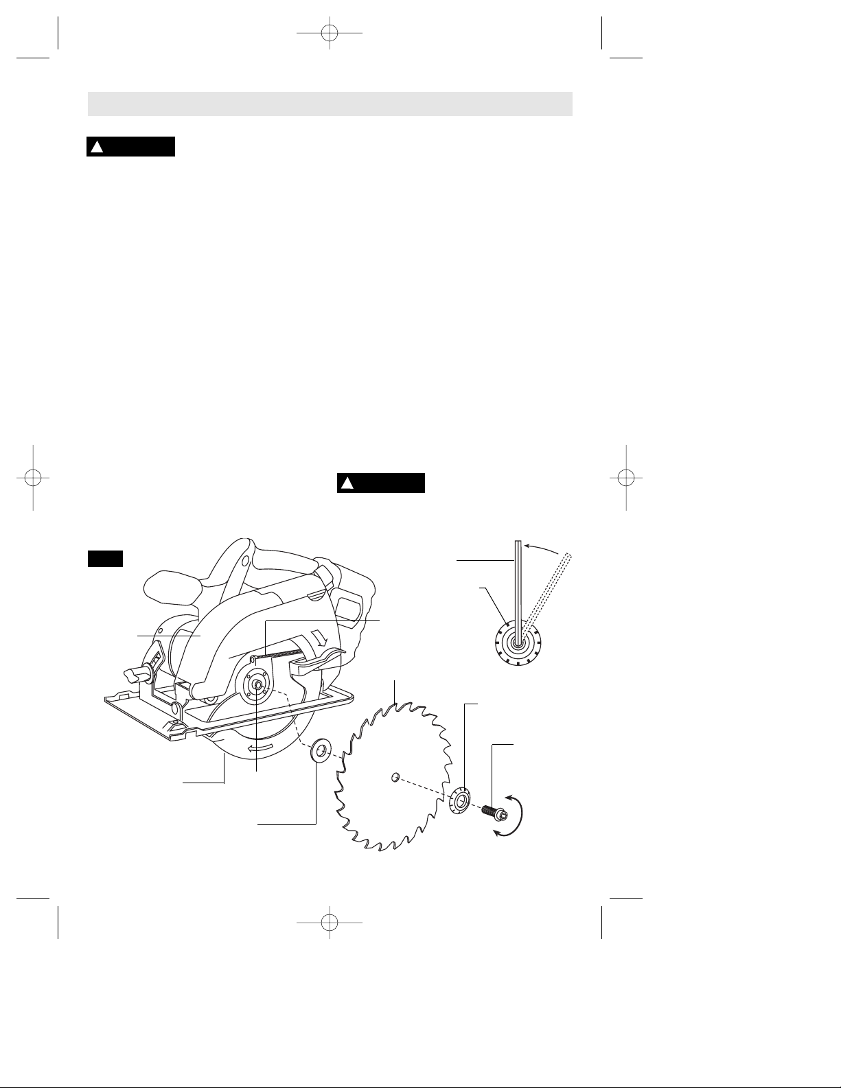
-35-
Ensamblaje
COLOCACION DE LA HOJA
Desconecte el paquete de
baterías de la herramienta o
ponga el interruptor en la posición fijada o de
apagado antes de hacer cualquier ensamblaje,
ajustes o cambiar accesorios. Dichas medidas
preventivas de seguridad reducen el riesgo de
arrancar la herramienta accidentalmente.
1. Gire el PERNO DE LA HOJA en sentido de las agujas
del reloj con la llave de tuerca suministrada y quite el
PERNO DE LA HOJA y la ARANDELA EXTERIOR (Fig. 2).
Si el eje se mueve al intentar aflojar el perno de la hoja,
oprima el botón de fijación.
2. Retraiga el protector inferior por completo hasta el
interior del protector superior. Mientras que retrae el
protector inferior, revise el funcionamiento y el estado
del MUELLE DEL PROTECTOR INFERIOR.
3. Asegúrese de que los dientes de la sierra y la flecha
de la hoja están dirigidos en la misma dirección que la
flecha del protector inferior.
4. Deslice la hoja a través de la ranura de la base y
móntela junto a la ARANDELA INTERIOR en el eje.
Asegúrese de que no queda espacio entre el diámetro
grande de las arandelas INTERIOR y EXTERIOR y la hoja.
5. Vuelva a instalar la ARANDELA EXTERIOR y apriete el
PERNO DE LA HOJA con los dedos. La cara de la
arandela exterior de la hoja tiene marcas a su alrededor
que le ayudarán a usted a ajustar adecuadamente el
espárrago de la hoja. Oprima el botón de fijación para
fijar el eje y APRIETE EL PERNO DE LA HOJA EN
SENTIDO CONTRARIO AL DE LAS AGUJAS DEL RELOJ
UNA MARCA EN LA ARANDELA DE LA HOJA CON LA
LLAVE DE TUERCA SUMINISTRADA.
No utilice llaves con mangos más largos, ya que pueden
hacer que el tornillo de la hoja quede excesivamente
apretado.
EMBRAGUE DE PAR MOTOR VARIABLE
Esta acción de embrague es proporcionada por la
fricción de la ARANDELA EXTERIOR contra la HOJA y
permite que el eje de la hoja gire cuando la hoja
encuentra una resistencia excesiva. Cuando el
TORNILLO DE LA HOJA está apretado adecuadamente
(tal como se describe en el No. 5 de Colocación de la
hoja), la hoja patinará al encontrar una resistencia
excesiva, por lo que reducirá la tendencia de la sierra al
RETROCESO.
Una posición de ajuste puede no ser suficiente para
cortar todos los materiales. Si la hoja patina demasiado,
apriete el tornillo de la hoja 1/2 marca más. EL APRETAR
EXCESIVAMENTE EL TORNILLO DE LA HOJA ANULA LA
EFICACIA DEL EMBRAGUE.
EXTRACCION DE POLVO
La herramienta está equipada con un adaptador del
orificio para polvo para la extracción de polvo y virutas.
Para utilizar este dispositivo, abra la tapa del orificio
para polvo, conecte una manguera de aspiración
(accesorio opcional) al orificio para polvo y conecte el
extremo opuesto de la manguera a una aspiradora de
taller.
Para evitar lesiones personales,
posicione siempre la manguera
de aspiración de manera que no interfiera con el
protector inferior ni con la operación de corte en
todas las posiciones.
ADVERTENCIA
!
ADVERTENCIA
!
FIG. 2
APRETAR
AFLOJAR
TORNILLO
DE LA HOJA
MUELLE DEL
PROTECTOR
INFERIOR
ARANDELA EXTERIOR
El diámetro grande está
en el lado de la hoja
ARANDELA INTERIOR
El diámetro grande está
en el lado de la hoja
HOJA
PROTECTOR
INFERIOR
EJE DE
LA HOJA
PROTECTOR
SUPERIOR
LLAVE
ARANDELA EXTERIOR
MARCA
BM 2610998757 11/01 11/2/01 3:32 PM Page 35
Page 36

-36-
Instrucciones de funcionamiento
Desconecte el paquete de baterías de la herramienta.
Afloje el pomo de ajuste de profundidad ubicado en el
lado trasero del protector superior. Sujete la base con
una mano y suba o baje la sierra con el mango. Fije el
pomo en la posición de ajuste de profundidad deseada.
Verifique la profundidad deseada (Fig. 3).
Para un astillado mínimo la longitud que debe sobresalir
por debajo del material que se va a cortar no debe ser de
más de un diente de hoja (Fig. 4).
INTERRUPTOR DE SEQURIDAD
El interruptor de seguridad está diseñado para prevenir
arranques accidentales. Para accionar el interruptor de
seguridad, oprima el botón de liberación con el dedo
pulgar en cualquiera de los dos lados del mango para
desacoplar el cierre y luego apriete el gatillo (Fig. 5). Al
soltar el gatillo, el botón acoplará el interruptor de
seguridad automáticamente y el gatillo dejará de
funcionar. (Vea Interruptor y Cortes generales en la
página 34.)
VERIFICACION DEL ANGULO DE CORTE DE 90˚
Desconecte el paquete de baterías de la herramienta.
Ajuste la base al valor de máxima profundidad de corte.
Afloje el pomo de ajuste de inclinación, ajuste a 0˚ en el
cuadrante, vuelva a apretar la palanca y verifique que
hay un ángulo de 90˚ entre la hoja y el plano inferior de
la base con una escuadra (Fig. 6). Si es necesario
realizar un ajuste, incline la base hasta 45°, apriete la
tuerca de mariposa de ajuste de inclinación y doble la
"LENGÜETA" con una llave de tuerca ajustable o con
unos alicates (Fig. 7).
FIG. 7
AJUSTE DE PROFUNDIDAD
0
2
1
FIG. 3
FIG. 4
UN DIENTE ES LA LONGITUD QUE
DEBE PENETRAR EN LA MADERA
PARA UN ASTILLADO MINIMO
POMO DE
AJUSTE DE
PROFUNDIDAD
SOPORTE DE
PROFUNDIDAD CALIBRADO
LLAVE DE HOJA Y
AREA PARA GUARDAR
90°
FIG. 5
FIG. 6
BOTON DE LIBERACION
DEL INTERRUPTOR DE
SEGURIDAD
LENGÜETA
POMO DE AJUSTE DE
INCLINACION
HOJA
GATILLO
BASE
BM 2610998757 11/01 11/2/01 3:32 PM Page 36
Page 37

-37-
GUIA DE LINEA
Para un corte recto de 90˚, utilice el lado derecho de la
muesca de la base. Para cortes inclinados de 45˚, utilice
el lado izquierdo (Fig. 9). La muesca de la guía de corte
proporcionará una línea de corte aproximada. Realice
cortes de prueba en madera de desecho para verificar la
línea de corte real. Esto servirá de ayuda debido al
número de diferentes tipos y espesores de hoja
disponibles. Para asegurar un astillado mínimo en el lado
bueno del material que se va a cortar, coloque el lado
bueno hacia abajo.
GUIA DE INTERRUPTOR
Para encender la herramienta (posición “ON”), apriete el
interruptor ga-tillo. Para apagar la herramienta (posición
“OFF”), suelte el interruptor gatillo, que está accionado
por muelle, y volverá a la posición “off”
automáticamente.
La sierra debe funcionar a toda velocidad ANTES de
comenzar el corte y se debe apagar únicamente
DESPUES que se haya terminado el corte. Para
aumentar la vida del interruptor, no apague y encienda el
interruptor mientras esté cortando.
FRENO
Cuando se suelta el gatillo, éste activa el freno eléctrico
para detener la hoja rápidamente. Este dispositivo es
especialmente útil cuando se hacen cortes repetitivos.
CORTES GENERALES
Sujete siempre el mango de la sierra con una mano y el
mango auxiliar o la caja protectora con la otra.
Asegúrese siempre de que la base suave descanse sobre
la parte de la superficie de trabajo que no vaya a caerse.
Assurez-vous que vos mains ne
gênent pas le mouvement de la
garde inférieure.
Agarre firmemente y accione el interruptor con una
acción decidida. Nunca fuerce la sierra. Utilice una
presión ligera y continua.
Después de completar un corte y
haber soltado el gatillo, tenga
en cuenta el tiempo que se necesita para que la hoja
se detenga por completo durante la desaceleración
con movimiento por inercia. No permita que la sierra
le roce la pierna o el lado, ya que como el protector
inferior es retráctil podría engancharse en la ropa y
poner la hoja al descubierto. Tenga en cuenta los
sitios en que la hoja está al descubierto por necesidad
tanto en las áreas del protector inferior como del
superior.
Cuando se interrumpe el corte, para seguir cortando:
apriete el gatillo y deje que la hoja se ponga a toda
velocidad, vuelva a entrar en el corte lentamente y siga
cortando.
Cuando se corta a contrahilo, las fibras de la madera
tienden a rasgarse y levantarse. El hacer que la sierra
avance lentamente minimiza este efecto. Para un corte
acabado se recomienda una hoja de corte transversal o
una hoja de cortar a inglete.
ADVERTENCIA
!
ADVERTENCIA
!
AJUSTE DE INCLINACION
Desconecte el paquete de baterías de la herramienta.
La base se puede ajustar hasta 50˚ aflojando el pomo de
ajuste de inclinación en la parte delantera de la sierra.
Alinee hasta alcanzar el ángulo deseado en el cuadrante
calibrado. Luego, apriete el pomo de ajuste de
inclinación (Fig. 8). Debido al aumento en la cantidad de
acoplamiento de la hoja en la pieza de trabajo y a la
disminución en la estabilidad de la base, se puede
producir el atasco de la hoja. Mantenga la sierra estable
y la base firme sobre la pieza de trabajo.
FIG. 9
CORTE
INCLINADO
DE 45°
CORTE VERTICAL
DE 90°
FIG. 8
POMO DE AJUSTE
DE INCLINACION
QUADRANT
BM 2610998757 11/01 11/2/01 3:32 PM Page 37
Page 38

-38-
CORTES DE BOLSILLOS
Desconecte el paquete de baterías de la herramienta
antes de realizar ajustes. Coloque el ajuste de
profundidad de acuerdo con el material que va a cortar.
Incline la sierra hacia adelante con la muesca de la guía
de corte alineada con la línea que usted ha trazado.
Levante el protector inferior utilizando la palanca de
elevación y sujete la sierra con los mangos frontal y
posterior (Fig. 10).
Con la hoja muy cerca del material que se va a cortar,
pero sin tocarlo, arranque el motor. Baje gradualmente la
parte posterior de la sierra utilizando el extremo frontal
de la base como punto de bisagra. ADVERTENCIA:
Cuando la hoja comience a cortar el material, suelte
el protector inferior inmediatamente. Cuando la base
descanse horizontalmente sobre la superficie que se está
cortando, siga cortando en dirección hacia adelante
hasta el final del corte. ADVERTENCIA: Deje que la hoja
se detenga por completo antes de sacar la sierra del
corte. Además, nunca intente mover la sierra hacia
atrás, ya que la hoja se saldrá del material y se
producirá RETROCESO. De la vuelta a la sierra y termine
el corte de manera normal, aserrando hacia adelante. Si
las esquinas del corte de bolsillo no están
completamente cortadas, utilice una sierra de vaivén o
una sierra de mano para terminar las esquinas.
CORTE DE PLANCHAS GRANDES
Las planchas grandes y los tableros largos se comban o
se doblan según el apoyo. Si usted intenta cortar sin
nivelar y sin apoyar la pieza adecuadamente, la hoja
tenderá a atascarse, produciendo RETROCESO y una
sobrecarga en el motor (Fig. 11).
Apoye el panel o el tablero cerca del corte, tal como se
muestra en la (Fig. 12). Asegúrese de ajustar la
profundidad de corte para cortar la plancha o el tablero
solamente y no la mesa o el banco de trabajo. Las tablas
de dos por cuatro pulgadas utilizadas para elevar y
apoyar la pieza de trabajo deben colocarse de manera
que los lados más anchos soporten la pieza de trabajo y
descansen en la mesa o en el banco. No apoye la pieza
de trabajo en los lados estrechos, ya que esta
disposición es inestable. Si la plancha o el tablero a
cortar es demasiado grande para una mesa o un banco
de trabajo, utilice los tablas de apoyo de dos por cuatro
pulgadas sobre el suelo y fije la pieza de trabajo.
CORTES AL HILO
La hoja combinada suministrada con la sierra sirve tanto
para cortes transversales como para cortes al hilo. El
corte al hilo consiste en cortar a lo largo siguiendo la veta
de la madera. Los cortes al hilo son fáciles de realizar
con un tope-guía para cortar al hilo (Fig. 13). El tope-guía
para cortar al hilo está disponible como accesorio (no
incluido). Para colocar el tope-guía, introdúzcalo a través
de las ranuras de la base hasta la anchura deseada tal
como se muestra en la ilustración y fíjelo con la pomo.
TABLERO-GUIA PARA CORTAR AL HILO
Cuando se cortan al hilo planchas grandes, puede que el
tope-guía para cortar al hilo no permita el ancho de corte
deseado. Sujete o clave una pieza recta de madera de 1"
(25mm) a la plancha como guía (Fig. 14). Utilice el lado
izquierdo de la base apoyándolo en la tablero-guía.
FIG. 10
FIG. 11
FIG. 12
INCORRECTO
CORRECTO
BASE
PALANCA DE
ELEVACION
DEL
PROTECTOR
INFERIOR
FIG. 13
FIG. 14
TOPE-GUIA PARA
CORTAR AL HILO
POMO
ANCHO DE
CORTE
DESEADO
LINEA DE
CORTE
DESEADA
TABLERO-
GUIA PARA
CORTAR AL
HILO
BM 2610998757 11/01 11/2/01 3:32 PM Page 38
Page 39

-39-
CARGA DEL PAQUETE DE BATERIAS (CARGADOR DE 1 HORA)
LUZ
INDICADORA
CARGADOR
PAQUETE DE BATERIAS
FIG. 15
NOTAS IMPORTANTES PARA CARGAR
1. El paquete de baterías acepta únicamente
alrededor del 80 por ciento de su capacidad máxima
en los primeros ciclos de carga. Sin embargo,
después de los primeros ciclos de carga, la batería se
cargará hasta su capacidad máxima.
2. El cargador fue diseñado para cargar la batería
rápidamente sólo cuando la temperatura de la batería
está entre 4°C (40°F) y 41°C (105°F).
3. Un descenso considerable en el tiempo de
funcionamiento por carga puede significar que el
paquete de baterías se está acercando al final de su
vida y que debe ser sustituido.
4. Si espera que haya largos períodos (es decir, un
mes o más) en los que no se use la herramienta, lo
mejor es hacerla funcionar hasta que esté
completamente descargada antes de guardar el
paquete de baterías. Después de un largo período de
almacenamiento, la capacidad después de la primera
recarga será más baja. La capacidad normal se
restaurará en dos o tres ciclos de carga/descarga.
Recuerde desenchufar el cargador durante el período
de almacenamiento.
5. Si la batería no carga adecuadamente:
a. Compruebe que hay tensión en el tomacorriente
enchufando algún otro dispositivo eléctrico.
b. Compruebe si el tomacorriente está conectado a
un interruptor de luz que corta el suministro de
energía cuando se apagan las luces.
c. Compruebe si hay suciedad en las terminales
del paquete de baterías. Límpielas con un pedazo de
algodón y alcohol si es necesario.
d. Si usted sigue sin obtener una carga adecuada,
lleve o envíe la herramienta, el paquete de baterías y
el cargador al Centro de servicio Bosch local. Busque
bajo “Herramientas eléctricas” en las páginas
amarillas para obtener nombres y direcciones.
Nota: La utilización de cargadores o paquetes de
baterías no vendidos por Bosch puede invalidar la
garantía.
Enchufe el cordón del cargador en un tomacorriente
eléctrico estándar y luego introduzca el paquete de
baterías en el cargador. El indicador verde del
cargador comenzará a "PARPADEAR". Esto indica que
la batería está recibiendo una carga rápida. La carga
rápida se detendrá automáticamente cuando el
paquete de baterías esté completamente cargado.
Cuando la luz indicadora deje de "PARPADEAR" (y
pase a ser una luz verde constante), la carga rápida se
habrá completado.
Cuando comience el proceso de carga del paquete de
baterías, una luz verde constante también podría
significar que el paquete de baterías está demasiado
caliente o demasiado frío.
El propósito de la luz es indicar que el paquete de
baterías se está cargando rápidamente. No indica el
punto exacto de carga completa. La luz dejará de
parpadear en menos mas tiempo hora si el paquete
de baterías no estaba completamente descargado.
Cuando el paquete de baterías esté completamente
cargado, desenchufe el cargador (a menos que vaya a
cargar otro paquete de baterías) y deslice el paquete
de baterías de vuelta en el interior del mango de la
herramienta (Fig. 15).
BM 2610998757 11/01 11/2/01 3:32 PM Page 39
Page 40

-40-
Servicio
NO HAY PIEZAS EN EL
INTERIOR QUE PUEDAN SER
AJUSTADAS O REPARADAS POR EL USUARIO. El
mantenimiento preventivo realizado por personal no
autorizado pude dar lugar a la colocación incorrecta
de cables y componentes internos que podría
constituir un peligro serio. Recomendamos que todo
el servicio de las herramientas sea realizado en un
Centro de servicio de fábrica Bosch o en una Estación
de servicio Bosch autorizada. TECNICOS DE
REPARACIONES: Desconecten la herramienta y/o el
cargador de la fuente de energía antes de realizar
servicio de ajustes y reparaciones.
BATERIAS
Esté alerta a los paquetes de baterías que estén
aproximándose al final de su vida útil. Los paquetes
de baterías duran normalmente de 500 a 1000 cargas.
Si observa una disminución del rendimiento de la
herramienta o un tiempo de funcionamiento
significativamente más corto entre cargas, entonces ha
llegado el momento de cambiar el paquete de baterías.
Si no se hace esto, el resultado puede ser que la
herramienta funcione incorrectamente o que el
cargador se dañe.
Cuando la batería se almacene a largo plazo, debe
estar en estado de descarga. Los paquetes de
baterías duran más y se recargan mejor cuando se
almacenan descargados. Recuerde recargar
completamente los paquetes de baterías antes de
utilizarlos después de un almacenamiento prolongado.
LUBRICACION DE LAS HERRAMIENTAS
Su herramienta Bosch ha sido lubricada
adecuadamente y está lista para la utilización.
MOTORES “CORRIENTE DIRECTA”
El motor de la herramienta ha sido diseñado para
muchas horas de servicio fiable. Para mantener un
rendimiento óptimo del motor, recomendamos que éste
sea examinado cada seis meses. Sólo se debe usar un
motor de repuesto Bosch genuino diseñado
especialmente para la herramienta.
RODAMIENTOS
Los rodamientos que se vuelven ruidosos (debido a la
pesada carga o al corte de materiales muy abrasivos)
deben ser sustituidos inmediatamente para evitar el
sobrecalentamiento y el fallo del motor.
Limpieza
Para evitar accidentes,
desconecte siempre la
herramienta y/o el cargador de la fuente de energía
antes de la limpieza. La herramienta se puede limpiar
más eficazmente con aire comprimido seco. Use gafas
de seguridad siempre que limpie herramientas con
aire comprimido.
Las aberturas de ventilación y las palancas de
interruptor deben mantenerse limpias y libres de
materias extrañas. No intente limpiar introduciendo
objetos puntiagudos a través de las aberturas.
Ciertos agentes de limpieza y
disolventes dañan las piezas de
plástico. Algunos de estos son: gasolina, tetracloruro
de carbono, disolventes de limpieza clorados, amoníaco
y detergentes domésticos que contienen amoníaco.
Mantenimiento
ADVERTENCIA
!
ADVERTENCIA
!
PRECAUCION
!
Si es necesario un cordón de
extensión, se debe usar un
cordón con conductores de tamaño adecuado que sea
capaz de transportar la corriente necesaria para la
herramienta. Esto evitará caídas de tensión excesivas,
pérdida de potencia o recalentamiento. Las herramientas
conectadas a tierra deben usar cordones de extensión
de 3 hilos que tengan enchufes de 3 terminales y
receptáculos para 3 terminales.
NOTA: Cuanto más pequeño es el número de calibre,
más grueso es el cordón.
TAMAÑOS RECOMENDADOS DE CORDONES DE EXTENSION
HERRAMIENTAS DE 120 V CORRIENTE ALTERNA
ADVERTENCIA
!
Capacidad
nominal en
amperes de la
herramienta
Tamaño del cordón en A.W.G.
Tamaños del cable en mm
2
3-6
6-8
8-10
10-12
12-16
18 16 16 14 0,75 0,75 1,5 2,5
18 16 14 12 0,75 1,0 2,5 4,0
18 16 14 12 0,75 1,0 2,5 4,0
16 16 14 12 1,0 2,5 4,0 —
14 12 — — — — — —
25 50 100 150 15 30 60 120
Longitud del cordón en pies Longitud del cordón en metros
Accesorios
(* = equipo estándar)
(** = accesorios opcionales)
* Cargador de una hora
* Tope-guía para cortar al hilo
* Hoja de carburo de 137 mm con 18 dientes para
separación de corte estrecha
** Hoja de carburo de 137 mm con 24 dientes para
separación de corte estrecha
** Cargador de 15 minutos
** Manguera "Airsweep" de 15 pies que se acopla a la
mayoría de aspiradoras
BM 2610998757 11/01 11/2/01 3:32 PM Page 40
Page 41

-41-
BM 2610998757 11/01 11/2/01 3:32 PM Page 41
Page 42

-42-
BM 2610998757 11/01 11/2/01 3:32 PM Page 42
Page 43

-43-
BM 2610998757 11/01 11/2/01 3:32 PM Page 43
Page 44

LIMITED WARRANTY OF BOSCH PORTABLE AND BENCHTOP POWER TOOLS
S-B Power Tool Company (“Seller”) warrants to the original purchaser only, that all BOSCH portable and benchtop power tools will be free from
defects in material or workmanship for a period of one year from date of purchase. SELLER’S SOLE OBLIGATION AND YOUR EXCLUSIVE REMEDY
under this Limited Warranty and, to the extent permitted by law, any warranty or condition implied by law, shall be the repair or replacement of
parts, without charge, which are defective in material or workmanship and which have not been misused, carelessly handled, or misrepaired by
persons other than Seller or Authorized Service Station. To make a claim under this Limited Warranty, you must return the complete portable or
benchtop power tool product, transportation prepaid, to any BOSCH Factory Service Center or Authorized Service Station. For Authorized BOSCH
Power Tool Service Stations, please refer to your phone directory.
THIS LIMITED WARRANTY DOES NOT APPLY TO ACCESSORY ITEMS SUCH AS CIRCULAR SAW BLADES, DRILL BITS, ROUTER BITS, JIGSAW
BLADES, SANDING BELTS, GRINDING WHEELS AND OTHER RELATED ITEMS.
ANY IMPLIED WARRANTIES SHALL BE LIMITED IN DURATION TO ONE YEAR FROM DATE OF PURCHASE. SOME STATES IN THE U.S., SOME
CANADIAN PROVINCES DO NOT ALLOW LIMITATIONS ON HOW LONG AN IMPLIED WARRANTY LASTS, SO THE ABOVE LIMITATION MAY NOT
APPLY TO YOU.
IN NO EVENT SHALL SELLER BE LIABLE FOR ANY INCIDENTAL OR CONSEQUENTIAL DAMAGES (INCLUDING BUT NOT LIMITED TO LIABILITY
FOR LOSS OF PROFITS) ARISING FROM THE SALE OR USE OF THIS PRODUCT. SOME STATES IN THE U.S. AND SOME CANADIAN PROVINCES
DO NOT ALLOW THE EXCLUSION OR LIMITATION OF INCIDENTAL OR CONSEQUENTIAL DAMAGES, SO THE ABOVE LIMITATION OR
EXCLUSION MAY NOT APPLY TO YOU.
THIS LIMITED WARRANTY GIVES YOU SPECIFIC LEGAL RIGHTS, AND YOU MAY ALSO HAVE OTHER RIGHTS WHICH VARY FROM STATE TO
STATE IN THE U.S., PROVINCE TO PROVINCE IN CANADA AND FROM COUNTRY TO COUNTRY.
THIS LIMITED WARRANTY APPLIES ONLY TO PORTABLE AND BENCHTOP ELECTRIC TOOLS SOLD WITHIN THE UNITED STATES OF AMERICA,
CANADA AND THE COMMONWEALTH OF PUERTO RICO. FOR WARRANTY COVERAGE WITHIN OTHER COUNTRIES, CONTACT YOUR LOCAL
BOSCH DEALER OR IMPORTER.
GARANTIE LIMITÉE DES OUTILS ÉLECTRIQUES PORTATIFS ET D'ÉTABLI BOSCH
S-B Power Tool Company (le « vendeur ») garantit à l'acheteur initial seulement que tous les outils électriques portatifs et d'établi BOSCH seront
exempts de vices de matériaux ou d'exécution pendant une période d'un an depuis la date d'achat. LA SEULE OBLIGATION DU VENDEUR ET LE
SEUL RECOURS DE L’ACHETEUR sous la présente garantie limitée, et en autant que la loi le permette sous toute garantie ou condition implicite qui
en découlerait, sera l’obligation de remplacer ou réparer gratuitement les pièces défectueuses matériellement ou comme fabrication, pourvu que
lesdites défectuosités ne soient pas attribuables à un usage abusif ou à quelque réparation bricolée par quelqu’un d’autre que le vendeur ou le
personnel d’une station-service agréée. Pour présenter une réclamation en vertu de cette garantie limitée, vous devez renvoyer l'outil électrique
portatif ou d'établi complet, port payé, à tout centre de service agréé ou centre de service usine. Veuillez consulter votre annuaire téléphonique
pour les adresses.
LA PRÉSENTE GARANTIE NE S’APPLIQUE PAS AUX ACCESSOIRES TELS QUE LAMES DE SCIES CIRCULAIRES, MÈCHES DE PERCEUSES, FERS
DE TOUPIES, LAMES DE SCIES SAUTEUSES, COURROIES DE PONÇAGE, MEULES ET AUTRES ARTICLES DU GENRE.
TOUTE GARANTIE IMPLICITE SERA LIMITÉE COMME DURÉE À UN AN À COMPTER DE LA DATE D’ACHAT. CERTAINS ÉTATS AMÉRICAINS,
CERTAINES PROVINCES CANADIENNES N’ADMETTANT PAS LE PRINCIPE DE LA LIMITATION DE LA DURÉE DES GARANTIES IMPLICITES, IL
EST POSSIBLE QUE LES LIMITATIONS CI-DESSUS NE S’APPLIQUENT PAS À VOTRE CAS.
EN AUCUN CAS LE VENDEUR NE SAURAIT ÊTRE TENU POUR RESPONSABLE DES INCIDENTS OU DOMMAGES INDIRECTS (INCLUANT, MAIS NE
SE LIMITANT PAS AUX PERTES DE PROFITS) CONSÉCUTIFS À LA VENTE OU L’USAGE DE CE PRODUIT. CERTAINS ÉTATS AMÉRICAINS ET
CERTAINES PROVINCES CANADIENNES N’ADMETTANT PAS LE PRINCIPE DE LA LIMITATION NI L’EXCLUSION DES DOMMAGES INDIRECTS ET
CONSÉQUENTIELS, IL EST POSSIBLE QUE LES LIMITATIONS OU EXCLUSIONS CI-DESSUS NE S’APPLIQUENT PAS À VOTRE CAS.
LA PRÉSENTE GARANTIE VOUS ACCORDE DES DROITS BIEN DÉTERMINÉS, Y COMPRIS POSSIBLEMENT CERTAINS DROITS VARIABLES DANS
LES DIFFÉRENTS ÉTATS AMÉRICAINS, PROVINCES CANADIENNES.
CETTE GARANTIE LIMITÉE NE S'APPLIQUE QU'AUX OUTILS ÉLECTRIQUES PORTATIFS ET D'ÉTABLI VENDUS AUX ÉTATS-UNIS D'AMÉRIQUE,
AU CANADA ET AU COMMONWEALTH DE PORTO RICO.POUR COUVERTURE DE GARANTIE DANS LES AUTRES PAYS, CONTACTEZ VOTRE
IMPORTATEUR OU REVENDEUR BOSCH LOCAL.
© S-B POWER TOOL COMPANY 4300 W. PETERSON AVENUE CHICAGO, IL 60646 USA
EXPORTADO POR: S.B. POWER TOOL COMPANY, CHICAGO, IL 60646, E.U.A.
IMPORTADO POR: ROBERT BOSCH S.A. DE C.V., CALLE ROBERT BOSCH NO. 405, ZONA
INDUSTRIAL TOLUCA, MÉXICO. C.P. 50070 TEL. (72) 792300
GARANTIA LIMITADA PARA HERRAMIENTAS MECANICAS PORTATILES Y PARA TABLERO DE BANCO BOSCH
S-B Power Tool Company ("el Vendedor") garantiza, únicamente al comprador original, que todas las herramientas mecánicas portátiles y para
tablero de banco BOSCH estarán libres de defectos de material o de fabricación durante un período de un año a partir de la fecha de compra. LA
UNICA OBLIGACION DEL VENDEDOR Y EL RECURSO EXCLUSIVO QUE USTED TIENE bajo esta Garantía Limitada y, hasta donde la ley lo permita,
bajo cualquier garantía o condición implícita por ley, consistirá en la reparación o sustitución sin costo de las piezas que presenten defectos de
material o de fabricación y que no hayan sido utilizadas incorrectamente, manejadas descuidadamente o reparadas incorrectamente por personas
que no sean el Vendedor o una Estación de servicio autorizada. Para efectuar una reclamación bajo esta Garantía Limitada, usted debe devolver el
producto, que consiste en la herramienta mecánica portátil o para tablero de banco completa, con el transporte pagado, a cualquier Centro de
servicio de fábrica o Estación de servicio autorizada. Para Estaciones de servicio autorizadas de herramientas mecánicas BOSCH, por favor,
consulte el directorio telefónico.
ESTA GARANTIA LIMITADA NO SE APLICA A ARTICULOS ACCESORIOS TALES COMO HOJAS PARA SIERRAS CIRCULARES, BROCAS PARA
TALADROS, BROCAS PARA FRESADORAS, HOJAS PARA SIERRAS DE VAIVEN, CORREAS PARA LIJAR, RUEDAS DE AMOLAR Y OTROS
ARTICULOS RELACIONADOS.
TODAS LAS GARANTIAS IMPLICITAS TENDRAN UNA DURACION LIMITADA A UN AÑO A PARTIR DE LA FECHA DE COMPRA. ALGUNOS
ESTADOS DE LOS EE.UU., ALGUNAS PROVINCIAS CANADIENSES NO PERMITEN LIMITACIONES EN CUANTO A LA DURACION DE UNA
GARANTIA IMPLICITA, POR LO QUE ES POSIBLE QUE LA LIMITACION ANTERIOR NO SEA APLICABLE EN EL CASO DE USTED.
EL VENDEDOR NO SERA RESPONSABLE EN NINGUN CASO DE NINGUN DAÑO INCIDENTAL O EMERGENTE (INCLUYENDO PERO NO LIMITADO A
RESPONSABILIDAD POR PERDIDA DE BENEFICIOS) QUE SE PRODUZCA COMO CONSECUENCIA DE LA VENTA O UTILIZACION DE ESTE
PRODUCTO. ALGUNOS ESTADOS DE LOS EE.UU. Y ALGUNAS PROVINCIAS CANADIENSES NO PERMITEN LA EXCLUSION O LIMITACION DE
LOS DAÑOS INCIDENTALES O EMERGENTES, POR LO QUE ES POSIBLE QUE LA LIMITACION O EXCLUSION ANTERIOR NO SEA APLICABLE EN
EL CASO DE USTED.
ESTA GARANTIA LIMITADA LE CONFIERE A USTED DERECHOS LEGALES ESPECIFICOS Y ES POSIBLE QUE USTED TAMBIEN TENGA OTROS
DERECHOS QUE VARIAN DE ESTADO A ESTADO EN LOS EE.UU., DE PROVINCIA A PROVINCIA EN CANADA.
ESTA GARANTIA LIMITADA SE APLICA SOLAMENTE A HERRAMIENTAS ELECTRICAS PORTATILES Y PARA TABLERO DE BANCO VENDIDAS EN
LOS ESTADOS UNIDOS DE AMERICA, CANADA Y EL ESTADO LIBRE ASOCIADO DE PUERTO RICO. PARA COBERTURA DE GARANTIA EN OTROS
PAISES, PONGASE EN CONTACTO CON SU DISTRIBUIDOR O IMPORTADOR LOCAL DE BOSCH.
2610998757 11/01 Printed in U.S.A.
BM 2610998757 11/01 11/2/01 3:32 PM Page 44
 Loading...