

Page 1
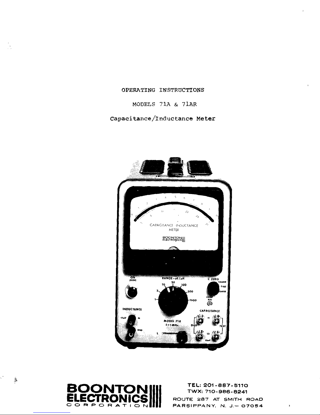
OPERATING INSTRUCTIONS
MODELS
71A
&
71AR
capacitance/Inductance
Meter
•
o
~
co
....
...
FINE
...
...•.
C
~
AOJ
@)
TEL:
201-887-5110
TWX:
710-986-8241
BOONTONIIII
ROUTE
287
AT
SMITH
ROAD
!=~~~~'!~~~~
PARSIPPANY,
N.
J.-
07054
Page 2
ADDENDUM
For
Model
7lA
and
7lA-R
'
s
having
serial
numbers
400
and
below.
The
front
panel
control
on
these
instruments,
called
"Cable
Comp",
is
referred
to
in
this
book
as
"Comp
Adj".
The
terminals
on
these
units
called
"STD"
are
referred
to
in
this
book
as
"DIFF".
It
should
be
noted
that
these
differences
are
in
nomenclature
only,
and
in
all
respects,
electrical
functions
as
described
in
this
instruction
book
remain
the
same
for
all
units.
A-I
71A
a
Page 3
Table
of
Contents
Page
1-1
Section
I
Specifications
Section
II
General
Description
2-1
2.1
General
Description~
Model
71A
2-1
2.2
General
Description~
Model
71AR
2-1
2.3
Location
of
controls
and
Adjustments~
Model
71A
2-2
2.4
Location
of
Controls
and
Adjustments~
Model
7lAR
2-3
2.5
Explanation
of
Controls
and
Adjustments
2-4
Section
III
Operating
Instructions
3-1
3.1
Initital
Installation
3-1
3.2
Capacitance
Measurements
3-3
3.3
Local
Capacitance
Measurements
3-3
3.4
Remote
Capacitance
Measurements
3-6
3.5
Increasing
Capacitance
Measuring
Range
3-10
3.6
Differential
Capacitance
Measurements
3-10
3.7
Extending
the
Range
of
the
C ZER0
Control
3-11
3.8
DC
Bias
for
Capacitance
Tests
3-11
3.9
Capacitance
Test
Signal
3-12
3.10
Capacitance
Calibration
Procedures
3-12
3.11
Inductance
Measurements
3-17
3.12
Connection
for
Inductance
Measurements
3-17
3.13
lnductance
Zero
Check
3-17
3.14
DC
output
3-18
3.15
IlMETER-OFp
lI
Switch
3-19
List
of
Replaceable
Parts
Following
Section
III
Schematics
Endfold
List
of
Figures
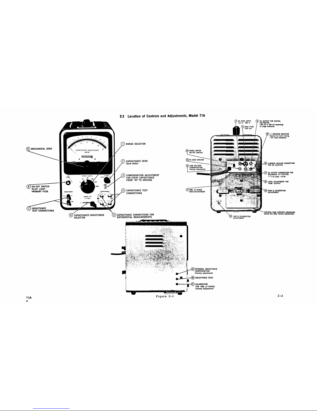
Figure
2-1
Location
of
Controls
and
Adjustments,
Model
71A
2-2
Figure
2-2_
Location
of
controls
and
Adjustments,
Model
7lAR
2-3
Figure
3-1
Correction
for
Series
Inductance
of
Connecting
Cables
3-9
71A
i
Page 4
Table
of
Contents
(cont'd)
Figure
3-2
Circuit
for
Applying
High
Voltage
DC
Bias
to
Capacitance
Specimens
3-13
Figure
3-3
Connection
Errors
for
Inductance
Measurements
at
1
MHz
3-20
ii
71A.
b
Page 5
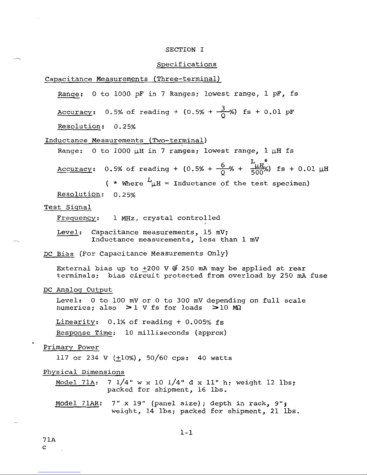
SECTION I
Specifications
C~acitance
Measurements
{Three-terminal}
Range:
0
-to
1000
pF
in
7
Ranges;
lowest
range,
1
pF,
fs
Accuracy:
0.5%
of
reading
+
(0.5%
+
~
%)
fs
+
0.01
pF
Resolution:
0.25%
Inductance
Measurements
{Two-terminal}
Range:
0
to
1000
~H
in
7
ranges;
lowest
range,
1
~H
fs
L *
Accuracy:
0.5%
of
reading
+
(0.5%
+
~
% +
5b~lo)
fs
+
0.01
~H
( *
Where
L~H
=
Inductance
of
the
test
specimen)
Resolution:
0.25%
Test
Signal
Freguency:
1
MHz~
crystal
controlled
.
Level:
Capacitance
measurements,
15
mV;
Inductance
measurements,
less
than
1
mV
DC
Bias
(For
Capacitance
Measurements
Only)
External
bias
up
to
+200
V @
250
rnA
may
be
applied
at
rear
terminals;
bias
circuit
protected
from
overload
by
250
rnA
fuse
DC
Analog
Output
Level:
0
to
100
mV
or
0
to
300
mV
depending
on
full
scale
numerics;
also
:> 1 V
fs
for
loads
:>
10
MO
Linearity:
0.1%
of
reading
+
0.005%
fs
Response
Time:
10
milliseconds
(approx)
Primary
Power
117
or
234
V
(+10%),
50/60
cps:
40
watts
Physical
Dimensions
Model
7lA:
7
1/4/1
w x
10
1/4/1 d xlI"
h;
weight
12
Ibs;
packed
for
shipment,
16
Ibs.
Model
71AR:
7"
x
19"
(panel
size);
depth
in
rack,
9";
weight,
14
Ibs;
packed
for
shipment,
21
lbs.
1-1
7lA
c
Page 6
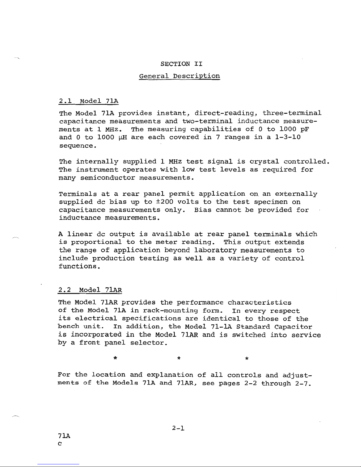
SECTION
II
General
Description
2.1
Model
7~
The
Model
71A
provides
instant,
direct-reading,
three-terminal
capacitance
measurements
and
two-terminal
inductance
measure-
ments
at
1 MHz.
The
measuring
capabilities
of
0
to
1000
pF
and
0
to
1000
~
are
each
covered
in
7
ranges
in
a
1-3-10
sequence.
The
internally
supplied
1
MHz
test
signal
is
crystal
controlled.
The
instrument
operates
with
low
test
levels
as
required
for
many
semiconductor
measurements.
Terminals
at
a
rear
panel
permit
application
on.
an
externally
supplied
dc
bias
up
to
±200
volts
to
the
test
specimen
on
capacitance
measurements
only.
Bias
cannot
be
provided
for
inductance
measurements.
A
linear
dc
output
is
available
at
rear
panel
terminals
which
is
proportional
to
the
meter
reading.
This
output
extends
the
range
of
application
beyond
laboratory
measurements
to
include
production
testing
as
well
as
a
variety
of
control
functions.
2.2
Model
7lAR
The
Model
7lAR
provides
the
performance
characteristics
of
the
Model
7lA
in
rack-mounting
form.
In
every
respect
its
electrical
specifications
are
identical
to
those
of
the
bench
unit.
In
addition,
the
Model
7l-lA
Standard
Capacitor
is
incorporated
in
the
Model
7lAR
and
is
switched
into
service
by
a
front
panel
selector.
*
*
*
For
the
location
and
explanation
of
all
controls
and
adjust-
ments
of
the
Models
71A
and
71AR,
see
pages
2-2
through
2-7.
2-1
7lA
c
Page 7
Page 8
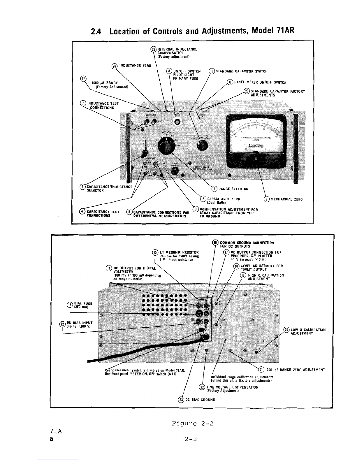
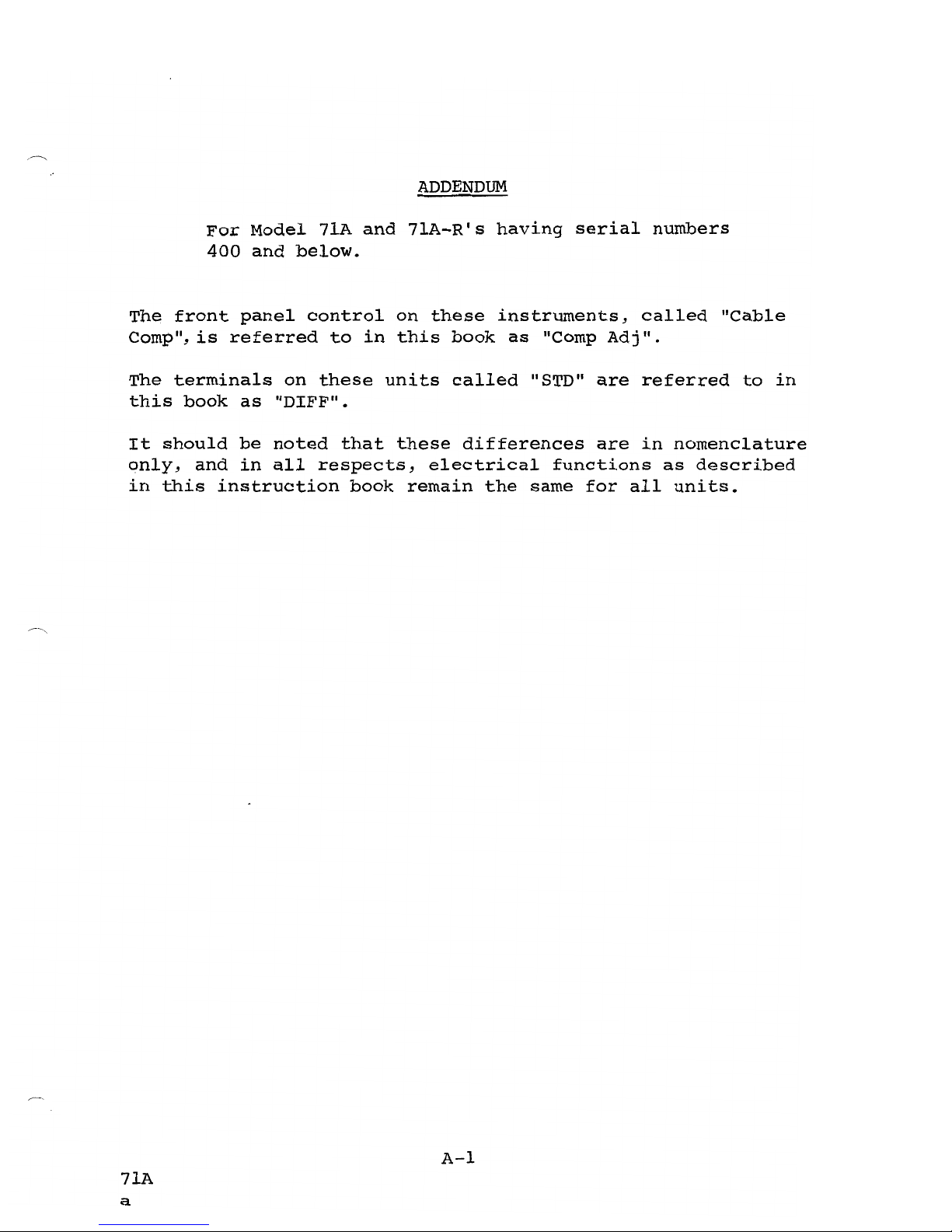
2.4
Location
of
Controls
and
Adjustments,
Model
71
AR
26
INDUCTANCE
ZERO
STANDARD
CAPACITOR
SWITCH
27
15
t.l
MEGOHM
RESISTOR
Remove
for
dvm's
having
1 Ma
input
resistance
DC
OUTPUT
FOR
DIGITAL
VOLTMETER
(100
mV
or
300
mV
depending
on
range
numerics)
12
DC
BIAS
INPUT
(up to ±200 V)
COMMON
GROUND
CONNECTION
FOR
DC
OUTPUTS
17
DC
OUTPUT
CONNECTION
FOR
RECORDER,
X·Y
PLOTTER
>1
V fnrJnads >10 M!l
LEVEL
ADJUSTMENT
FOR
"DVM"
OUTPUT
19
HIGH Q CALIBRATION
ADJUSTMENT
LOW Q CALIBRATION
ADJUSTMENT
21
lODD
pF
RANGE
ZERO
ADJUSTMENT
Individual
range
calibration
adjustments
behind this plate (factory adjustments)
LINE
VOLTAGE
COMPENSATION
(Factory Adjustment)
Figure
2-2
71A
a
2-3
Page 9
2.5
Explanation
of
Controls
and
Adjustments
2.5.1
Front
Panel,
Models
7lA
and
71AR
RANGE
-
pF!~:
Seven-position
switch
selects
measuring
ranges
having
full
scale
values
of
1,
3,
10,
30,
100,
300,
or
1000,
with
units
of
measurement
being
either
picofarads
or
microhenries,
as
determined
by
the
position
of
the
"L/C"
selector.
C ZERO:
Provides
means
for
balancing
out
capacitance
across
the
"TEST"
terminals
(up
to
approximately
7
pF)
contributed
by
exposed
terminations
of
connecting
cables,
test
fixtures,
etc.
Its
range
may
be
increased
by
attach-
ing
an
external
capacitance
to
the
"DIFF"
posts,
as
out-
lined
in
paragraph
3.7.
NOTE
This
is
a
dual
ratio
control
which
adjusts
a
variable
air
capacitor
having
a
full
3600 of
rotation.
It
will
be
noted
that
for
about
2700 of
rotation
of
the
"c
ZERO"
con-
trol,
it
turns
very
easily.
Beyond
this
point
the
torque
requirGment
increases
abruptly,
indicating
a
shift
from
the
36:1
"fine"
ratio
to
the
6:1
"coarse"
ratio.
COMP
ADJ:
The
front
panel
"COMP
ADJ"
control
adjusts
a
variable
air
capacitor
which
negates
stray
capacitance
from
the
high
postto
ground
(such
as
those
existing
be-
tween
the
inner
and
outer
conductors
of
coaxial
cable)
to
eliminate
its
effects
on
measurements.
This
control
will
tune
out
approximately
100
pF.
As
a
rule
of
thumb,
the
amount
of
"HI"-post-to-grourrlcapacitance
required
to
cause
1%
of
full-scale
error
is
somewhat
greater
than
two
times
the
full
scale
value
of
the
range
for
all
ranges.
Thus,
it
can
be
seen
that
the
amount
of
"HI"-post-to-ground
capacitance
encountered
in
the
great
majority
of
cases
will
be
of
minor
significance,
and
require
balancing
only
on
the
lower
ranges.
However,
when
working
on
the
30
pF
range
or
lower,
the
"COMP
ADJ"
adjustment
should
be
checked
when:
(a)
The
instrument
is
initially
put
intq
service.
(b)
Any
change
is
made
in
the
connection
system.
(For
example,
going
from
remote
measurements
to
local
measurements
or
vice
versa,
changing
connecting
cables
or
test
fixtures,
etc.).
2-4
7lA
Page 10
(c)
-Measuring
a
standard
capacitor.
(d)
Testing
a
specimen
having
markedly
different
"HI"-to-ground
capacitance
than
those
tested
previously
with
a
given
connection
system
(as
caused
by
considerable
differences
in
internal
construction,
encasing,
or
terminations).
~
CAPACITANCE
TEST:
BNC
connectors
for
the
test
specimen.
Measurements
may
be
made
either
locally
or
remotely
by
means
of
coaxial
cables.
CAPACITANCE
DIFF:
A
given
capacitance
connected
to
the
"TEST"
terminals
produces
an
accurately
calibrated
up-scale
reading.
Attaching
the
same
capacitance
to
the
"DIFF"
post
causes
a
comparable
down-scale
reading.
These
connections
are
useful
for
such
functions
as
making
differential
capaci-
tance
measurements,
extending
the
measuring
range
upwards,
or
extending
the
range
of
the
"c
ZERO"
control.
There
are
certain
limitations
on
the
use
of
the
"DIFF"
posts
which
are
detailed
in
paragraphs
3.5, 3.6,
and
3.7.
~
L/c:
This
switch
selects
a
condition
for
measurement
of
either
inductance
or
capacitance.
INDUCTANCE:
Test
terminals
for
inductance
measurements.
Measurements
should
be
made
directly
at
the
terminals.
Use
of
even
short
test
leads
should
be
avoided,
if
possible.
<:~
ON
(PUSH):
The
main
power
switch
(push
for
on,
pull
for
.
off)
i
the
translucent
red
button
serves
as
the
pilot
light.
This
assembly
also
contains
the
primary
power
fuse,
which
may
be
removed
by
rotating
the
black
ring
counterclockwise
and
withdrawing
the
fuse
holder.
~
MECHANICAL
ZERO:
This
adjusts
the
meter
pointer
to
a
mechanical
zero.
It
should
be
checked
with
the
instrument
switched
off.
I
I
@ OPERATE/CAL
l/CAL
2
(Model
7lAR
only):
For
measuring,
th~s
selector
is
left
in
the
lIOPERATElI
position.
Set
the
"CAL
1"
and
"CAL
2",
it
switches
in
the
internal
100
pF
standard
capacitor
for
high-Q
and
low-Q
calibration
checks,
respec~ively.
(See
paragraph
3.10.4.)
METER
ON/OFF
(Model
71AR
only):
There
is
no
interaction
between
the
indicating
meter
and
the
dc
output
except
for
a
small
counter-emf
from
the
moving
coil
of
the
meter
move-
2-5
7lA
Page 11
mente
with
varying
meter
readings,
this
emf
may
show
up
as
slight
irregularities
in
the
dc
output:
switching
the
meter
off
eliminates
this.
In
addition,
switching
the
meter
off
eliminates
needless
wear
of
the
meter
movement
when
the
dc
output
is
used
for
widely
varying
test
values.
(In
the
Model
71A,
this
function
is
performed
by
the
rear!
panel
"METER
ON/OFF"
switch,
control
#22.)
This
control
is
inoperative
on
the
71A-R.
2.5.2
Rear
Panel,
Models
71A
and
71AR
±
BIAS:
This
terminal
and
BIAS
GND
(#23)
provide
for
appli-
cation
of
the
dc
bias
voltage
up
to
±200
volts
at
250
rnA
to
the
capacitance
test
specimen.
Bias
voltage
appears
across
both
"TEST"
and
"DIFF"
terminals.
FUSE:
250
rnA
fuse
prevents
internal
damage
in
case
the
bias
voltage
is
short-circuited
at
the
"TEST"
or
"DIFF"
terminals
either
by
accidental
contact
or
by
a
shorted
test
specimen.
See
paragraph
3.8·
for
further
details.
®
DVM+:
Connection
to
this
terminal
and
the
"GND"
terminal
(#16)
irrmediately
below
provides
a
dc
analog
of
the
measured
value
suitable
for
use
with
a
digital
voltmeter.
Output
for
full-scale
is
100
mV
or
300
mV
depending
upon
numerics
of
the
selected
range,
so
that
when
ranges
are
switched
the
dvm
follows
automatically.
~
1.1
Mn
RESISTOR:
For
dvm's
having
an
input
resistance
of
10
megohms
or
greater,
this
resistor
should
be
left
in
posi-
tion.
For
dvm's
having
an
input
resistance
of
1
megohm,
it
should
be
removed.
GND:
Ground
connection
for
DVM
or
REC
output.
REC:
connection
to
this
terminal
and
to
the
"GOO"
terminal
(#16)
provides
a
linear
analog
output
of
the
measured
value,
whose
level
varies
from
0
to
approximately
1.7
volts
(into
loads
greater
than
10
megohms)
for
full-scale
on
all
ranges.
DVM
ADJ:
This
control
adjusts
the
level
of
the
de
analog
output
so
that
the
dvm
will
be
in
agreement
with
a
standard
capacitor.
See
paragraph
3.14.4.
CAL
1:
Calibration
adjustment
for
high
Q
measurements.
For
calibration
procedures,
see
paragraph
3.10.
2-6
71A
b
Page 12
CAL
2:
Calibration
adjustment
for
low
Q
measurements.
For
calibration
procedures,
see
paragraph
3.10.
1000
pF
ZERO:
Zero
adjustment
for
1000
pF
range.
Once
set
on
initial
installation,
this
control
will
rarely
need
re-
adjustment.
However,
since
the
setting
of
this
control
is
vital
to
proper
operation
for
either
capacitance
or
induc-
tance
measurements,
it
is
recommended
that
it
be
checked
periodically.
(See
paragraph
3.1.4,
(f)
&
(g)
for
procedure.)
Line
Voltage
Compensation:
Factory
adjustment
to
assure
insensitivity
to
line
voltage
changes
from
105
to
125
V,
ac.
GND:
Ground
connection
for
dc
bias
input.
METER
ON/OFF,
Model
71A
only):
There
is
no
interaction
between
the
indicating
meter
and
the
dc
output
except
for
a
small
counter-emf
from
the
moving
coil
of
the
meter
move-
ment.
With
varying
meter
readings,
this
emf
may
show
up
as
slight
irregularities
in
the
dc
output~
switching
the
meter
off
eliminates
this.
NOTE:
In
the
Model
71A.R
this
function
is
performed
by
front
panel
switch
#11.
While
this
swi~ch
is
present
at
the
rear
of
the
Model
71AR,
it
is
disabled.
2.5.3
Model
7lAz Left
side~
Model
7lAR,
Top
INTERNAL
INDUCTANCE
COMPENSATION:
This
factory
adjustment
compensates
for
inductance
of
internal
wiring.
Pre-set
at
the
factory,
this
control
does
not
require
readjustment.
L ZERO:
This
control
provides
a
means
for
zeroing
the
in-
strument
on
the
1
~H
range
in
accordance
with
the
procedure
outlined
in
paragraph
3.13.
1000
WH
CALIBRATION:
This
control
provides
means
for
in-
dividually
calibrating
the
1000
~
range~
it
is
pre-set
at
the
factory
and
does
not
require
readjustment.
Adjustments
for
the
internal
100
pF
standard
capacitor.
These
are
set
at
the
factory
and
do
not
require
readjustment.
2-7
7lA
b
Page 13

L
SECTION
III
Operating
Instructions
3.1
Initial
Installation
3.1.1
Unpacking
On
unpacking~
inspect
the
instrument
for
possible
damage
in
transit.
If
the
instrument
is
damaged~
contact
your
local
Sales
Engineering
Representative
or
the
factory
(see
title
page
for
factory
address)
for
further
instructions.
If
no
damage
is
found~
the
instrument
may
be
put
into
service
by
the
following
procedure:
3.1.2
Mechanical
Zero
Adjustment
with
the
instrument
unpowered
and
in
a
normal
operating
position~
check
to
see
that
the
indicator
needle
rests
at
zero.
If
not~
set
to
zero
by
adjusting
the
mechanical
zero
control
on
the
meter
housing.
3.1.3
Turn-on
Procedure
and
Warm-up
Plug
the
instrument
into
a
source
of
117
V (±10%)
50/60
HZ
power
and
push
the
front
panel
ON
button.
(Note:
The
translucent
red
center
button
of
the
ON
switch
also
serves
as
the
pilot
light.
This
switch
is
turned
off
by
pulling
the
outer
black
disk
outward.
It
should
be
noted
that
this
switch
also
serves
as
the
fuse
holder.
(To
remove
the
fuse~
turn
the
switch
off~
twist
the
black
ring
counterclockwise~
and
withdraw
the
assembly.)
The
instrume~t
may
be
operated
approximately
30
seconds
after
turn-on.
However~
for
maxi-
mum
accuracy~
a
warm-up
of
approximately
a
half-hour
should
be
allowed.
3.1.4
Initial
Installation
Checks
and
Adjustments
3.1.4.1
General
Before
the
instrument
is
put
into
service,
there
are
several
initial
checks
which
should
be
made~
and~
if
necessary,
adjustments
perfor.med:
3.1.4.2
(a)
Allow
an
initial
warm-up
of
a
half
hour.
(b)
Set
the
Llc
selector
to
C.
3-1
71A
c
Page 14

(c)
With
the
instrument
on
the
1
pF
range~
and
no
specimen
connected
to
the
"TEST"
terminals,
set
the
indicator
to
about
75%
of
full
scale
using
the
front
panel
"c
ZERO"
control.
(d)
Adjust
the
front
panel
"COMP
ADJ"
control
for
a
peak
reading.
(Readjust
the
"c
ZERO"
control
to
keep
indications
on-scale
if
necessary)
.
(e)
Having
achieved
a
peak
reading~
return
the
indicator
to
zero
using
the
"c
ZERO"
control.
(f)
Switch
to
the
1000
pF
range~
and
observe
the
zero
position
of
the
indicator.
If
required~
set
to
zero
using
the
"1000
pF
ZERO"
at
the
rear
panel.
(g)
Switch
one
range
at
a
time
back
to
the
1
pF
range,
observing
the
zero
position
of
the
indicator
for
each
range.
If
the
zero
posi-
tion
shifts
appreciably
for
any
range,
re-
peat
steps
(c)
through
(g).
When
properly
adjusted,
the
zero
position
should
be
con-
stant
for
all
ranges.
NOTE
Once
properly
set,
the
"1000
pF
ZERO"
rarely
needs
readjustment.
However~
since
its
set-
ting
is
essential
to
the
proper
operation
of
the
instrument
for
either
capacitance
or
inductance
measurement,
it
is
advisable
to
check
it~
following
steps
(f)
and
(g)
above,
at
fairly
frequent
intervals.
(h)
Stretch
a
short
length
of
#22
copper
wire
between
the
"INDUCTANCE"
terminals.
(j)
Switch
the
"L/C"
switch
to
the
"L"
posi-
tion.
The
indicator
should
rest
one
minor
division
up-scale
from
zero.
If
not~
ad-
just
for
this
reading
using
the
"L
ZERO"
control
(the
center
adjustment
on
the
left
side
of
the
instrument).
3-2
71A
d
Page 15

3.2
capacitance
Measurements
With
the
front
panel
IIL-C
II
selector
in
the
"C
II
position~
the
Models
71A
and
71AR
measure
the
"direct"
capacitance
of
the
test
specimen.
(The
instruments
ignore
stray
capacitance
from
the
"LO"
post
to
ground.
Up
to
about
100
pF
of
capaci-
tance
from
the
"HI"
post
to
ground
can
be
nulled
by
adjust-
ment
of
the
"COMP
ADJ"
control.
As
a
result~
the
Models
71A
and
71AR
measure
only
the
capacitance
appearing
between
the
"HI"
and
"LO"
terminals.)
The
measurements
may
be
made
either
at
the
"TEST"
terminals
or
remotely
by
connecting
the
specimen
or
test
fixture
via
'
coaxial
cables
to
the
"TEST"
terminals.
By
use
of
both
the
"DIFF"
and
"TEST"
terminals
differential
capacitance
measure-
ments
may
be
made
within
certain
limitations.
3.3
Local
Capacitance
Measurements
3.3.1
Connections
for
Local
Measurements
While
the
capacitance
connectors
of
the
Models
7lA
and
7lAR
are
intended
primarily
for
attachment
of
coaxial
cables~
tests
may
readily
be
made
locally
by
connecting
the
speci-
men
directly
to
the
te~inals.
A
pair
of
Type
UG-1090/U
or
comparable
BNC-to-binding-post
adapters
are
particularly
convenient
for
this
purpose~
although
for
quick
measurements
the
leads
of
the
component
may
be
simply
inserted
in
the
center
receptables
of
the
BNC
terminals.
NOTE
If
any
length
of
coaxial
cables
is
used
for
connection~
even
if
they
are
only
a
few
inches
in
length~
the
measurement
is
considered
not
local~
but
is
remote
and
the
instructions
of
paragraph
3.4
apply.
3.3.2
Checks
and
Adjustment
Prior
to
Making
Local
Measurements
There
are
three
controls
whose
adjustment
should
be
checked
before
measuring
at
the
terminals
of
the
Model
71A
or
71AR:
(a)
"1000
pF
ZERO"
(b)
"COMP
ADJ
II
(c )
"C
ZERO"
3-3
71A
d
Page 16

3.3.2.1
111000
pF
ZERO"
Adjustment
The
111000
pF
ZERO"
control
is
located
at
the
rear
panel.
Its
setting
is
checked
by
switching
to
the
1000
pF
range
and,
with
no
specimen
attached
at
the
IITEST
If
terminals,
observing
the
rest
position
of
the
pointer.
If
it
does
not
read
zero,
follow
the
adjustment
procedure
outlined
in
paragraph
3.1.4,
(f)
and
(g).
3.3.2.2
IICOMP
ADJ
II
Peaking
Adjustment
Prior
to
measuring
at
the
IITEST
II
terminals,
the
IICOMP
ADJ"
peaking
adjustment
should
be
performed
as
follows:
(a)
Attach
any
terminal
adapters
or
connectors
to
be
used
for
subsequent
measurements
to
the
IITEST
II
terminals
and
set
the
"RANGE"
selector
to
the
1
pF
range.
(b)
Adjust
the
"c
ZERO"
control
for
a
reading
of
approximately
75%
of
full
scale.
(e)
Adjust
the
IICOMP
ADJ
II
control
for
a
maximum
reading.
(Readjust
the
"c
ZERO"
control
to
keep
deflections
on
scale
if
required.)
(d)
After
peaking,
zero
the
pointer
using
the
lie ZERO"
control.
Once
adjusted,
the
"COMP
ADJ
II
control
need
not
be
re-
adjusted
(although
periodic
checking
during
extended
periods
of
operation
is
advisable)
unless
some
change
in
either
the
method
of
connection
or
the
nature
of
the
test
samples
substantially
affects
the
stray
capacitance
from
the
"HI"
post
to
ground.
In
such
cases,
readjust-
ment
pf
the
"COMP
ADJ"
control
is
required.
The
above
"COMP
ADJ"
adjustment
procedure
will
suffice
for
the
majority
of
measurements
at
the
terminals
for
all
ranges.
However,
to
obtain
the
greatest
possible
accuracy
when
measuring
high
Q
(>10)
components
on
the
1,
3,
10
or
30
pF
range,
and
when
the
test
sample
has
significant
capacitance
from
the
IIHI
JI
post
to
ground,
the
following
procedure
should
be
follows:
(a)
Attach
whatever
terminal
adapters
or
connectors
are
to
be
used
in
subsequent
measurements
to
the
"TEST"
posts
and
connect
a
specimen
typical·of
3-4
7lA
Page 17

those
to
be
measured.
If
no
connectors
are
to
be
used,
insert
the
leads
of
the
specimen
in
the
center
conductors
of
the
"TEST"
posts.
(b)
Set
the
"RANGE"
selector
to
the
lowest
range
on
w.mch a
reading
of
approximately
75%
of
full
scale
is
possible.
(On
the
lower
ranges
the
"C ZERO"
control
may
be
of
help
in
obtaining
this
reading.)
(c)
Adjust
the
"COMP
ADJ"
for
peak
reading.
(Readjust
the
tIC
ZERO"
to
keep
deflections
on
scale
if
necessary.)
(d)
Disconnect
the
specimen
from
the
low
post,
leav-
ing
any
terminal
adapters
to
be
used
for
subse-
quent
tests
in
position;
zero
the
pointer
with
the
"c
ZERO"
control.
3.3.2.3
IIC ZERO"
Adjustment
The
front
panel
"c
ZERO"
adjustment
is
checked
by
switching
to
the
1
pF
range.
with
the
"COMP
ADJ"
control
properly
peaked
and
no
specimen
across
the
test
terminals,
observe
the
rest
position
of
the
pointer.
If
necessary,
the
pointer
should
be
brought
to
zero
using
the
front
panel
control.
Any
terminal
adapters
to
be
used
in
subsequent
measurements
should
be
left
installed
for
this
adjustment.
with
"100
pF
ZERO"
and
"c
ZERO"
controls
properly
set,
the
instrument
will
be
correctly
zeroed
for
all
ranges,
assuming
the
"COMP
ADJ"
control
is
properly
adjusted.
It
is
advisable
to
check
the
1
pF
zero
position
periodi-
cally
during
the
course
of
operation,
particularly
if
working
on
the
1
or
3
pF
ranges.
NOTE
The
front
panel
"c
ZERO"
control
is
a
dual
ratio
control
which
adjusts
a
variable
air
capacitor
having
a
full
3600 of
rotation.
It
will
be
noted
that
the
"C
ZERO"
control
turns
very
easily
for
about
2700 of
rotation.
At
this
point
the
torque
requirement
increases
abruptly,
indicating
a
shift
from
the
36:1
"fine"
adjustment
to
the
6:1
"coarse"
adjustment.
3-5
71A
Page 18

3.4
Remote
Capacitance
Measurements
3.4.1
Connections
for
Remote
Measurements
A
test
specimen
or
a
test
fixture
m~cted
to
the
"TEST"
terminals
by
coaxial
cables.
RG-62
is
particularly
recommended
for
this
purpose
because
0
its
low
capacitance.
To
minimize
errors
in
measurement
resulting
from
the
series
inductance
of
the
coaxial
cable,
the
length
of
each
of
the
two
cables
should
be
less
than
approximately
5
feet
on
the
1,
3,
and
10
pF
ranges,
with
shorter
lengths
on
higher
ranges.
Figure
3-1,
which
indicates
correction
factors
for
cable
inductance,
may
be
used
as
a
guide
in
selecting
prac-
tical
cable
lengths.
3.4.2
Initial
Adjustment
for
Remote
Measurements
There
are
three
controls
whose
adjustment
should
be
checked
before
making
remote
measurements
with
this
instrument:
(a)
"1000
pF
ZERO"
(b)
"COMP
ADJ"
(c)
rIC ZERO"
3.4.2.1
"1000
pF
ZERO"
Adjustment
The
"1000
pF
ZERO"
control
is
located
at
the
rear
panel.
Its
setting
is
checked
by
switching
to
the
1000
pF
range
and,
with
no
specimen
attached
at
the
"TEST"
terminals,
observing
the
rest
position
of
the
pointer.
If
it
does
not
read
zero,
follow
the
adjustment
procedure
outlined
in
paragraph
3.1.4,
(f)
and
(g).
3.4.2.2
"COMP
ADJ"
Peaking
Adjustment
Prior
to
measuring
remotely,
the
"COMP
ADJ"
peaking
adjust-
ment
must
be
performed
as
follows:
(a)
Connect
the
coaxial
cables
and
test
fixture
(if
any)
to
be
used
in
subsequent
measurements
to
the
"TEST"
terminals.
Set
the
range
selector
to
the
1
pF
range.
(b)
Adjust
the
"e ZERO"
control
for
a
reading
of
approximately
75%
of
full
scale.
3-6
7lA
Page 19

(c)
Adjust
the
"CaMP
ADJ"
control
for
a
maximum
reading.
(Readjust
the
"e
ZERO"
control
to
keep
deflections
on
scale
if
required).
(d)
After
peaking~
zero
the
pointer
using
the
"c
ZERO"
control.
Once
adjusted~
the
"CaMP
ADJ"
control
need
not
be
re-
adjusted
for
some
time
(although
periodic
checking
during
extended
periods
of
operation
is
advisable)
unless
some
change
in
either
the
connection
system
or
the
nature
of
the
test
samples
substantially
effects
the
stray
capacitance
from
the
"HI"
post
to
ground.
In
such
cases~
readjustment
of
the
"CaMP ADJ"
control
is
required.
The
above
"CaMP
ADJ"
adjustment
procedure
will
suffice
for
the
majority
of
remote
measurements.
However,
to
obtain
the
greatest
possible
accuracy
when
using
the
l~
3~
10
or
30
pF
range,
and
when
the
specimen
has
sig-
nificant
capacitance
from
the
"HI"
post
to
ground,
the
following
procedure
should
be
followed:
(a)
Attach
the
coaxial
cables
and
test
fixture
(if
any)
which
are
to
be
used
in
subsequent
measure
ments
to
the "..
TEST"
posts
and
connect
a
specimen
typical
of
those
to
be
measured.
(b)
Set
the
"RANGE"
selector
to
the
lowest
range
on
which~
using
the
"C ZERO"
control~
a
reading
of
approximately
75%
of
full
scale
is
possible.
(c)
Adjust
the
"CaMP
ADJ"
for
peak
reading.
(Re-
adjust
the
"c
ZERO"
to
keep
deflections
on
scale
if
necessary.)
(d)
Disconnect
the
cable
at
the
low
post
and
zero
the
pointer
with
the
lie
ZERO"
control
(see
paragraph
3.4.2.3
below).
3.4.2.3
"C
ZERO"
Adjustment
The
front
panel
"e
ZERO"
adjustment
is
checked
by
switch-
ing
to
the
1
pF
range.
with
the
"CaMP ADJ"
control
properly
peaked
and
no
specimen
across
the
test
terminals
observe
the
rest
position
of
the
pointer.
If
necessary,
the
pointer
should
be
brought
to
zero
using
the
front
panel
"e ZERO"
control.
(The
coaxial
cables
and
test
3-7
71A
Page 20

fixture
to
be
used
in
subsequent
measurements
should
be
attached
for
this
adjustment.)
with
the
111000
pF
ZERO"
and
"c
ZERO"
controls
properly
set,
the
instrument
will
be
correctly
zeroed
for
.all
ranges,
assuming
the
"COMP
ADJ
II
control
is
properly
adjusted.
It
is
advisable
to
check
the
1
pF
zero
position
periodi-
cally
during
the
course
of
operation,
particularly
if
working
on
the
1
or
3
pF
ranges.
NOTE
The
front
panel
IIC
ZERO"
control
is
a
dual
ratio
control
which
adjusts
a
variable
air
capacitor
having
a
full
3600 of
rotation.
It
will
be
noted
that
the
"C
ZERO
II
control
turns
very
easily
for
about
2700 of
rotation.
At
this
point
the
torque
requirement
increases
abruptly,
indicating
a
shift
from
the
36:1
IIfine
ll
adjustment
to
the
6:1
"coarse"
adjustment.
If
it
is
found
that
the
"c
ZERO"
range
is
inadequate
to
zero
out
the
external
capacitance,
its
range
may
be
extended
as
outlined
in
paragraph
3.7.
3.4.3
Errors
in
Capacitance
Measurements
Resulting
from
Series
Inductance
of
Connecting
Cables.
The
measured
capacitance,
Cm,
of
a
specimen
may
differ
from
the
true
capacitance,
Ct,
as
a
result
of
the
series
inductance
of
connecting
cables,
and
the
inductance
of
the
specimen.
The
error
will
be
noted
as
an
apparent
increase
in
capaci-
tance
value
in
accordance
with
the
following
expression:
Where
L =
the
combined
series
inductance
in
micro-
henries
of
BOTH
lengths
of
connecting
coaxial
cable
and
the
inductance
of
the
sample
(generally
small
with
respect
to
the
cable
inductance).
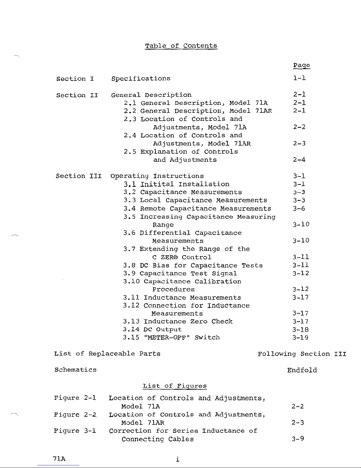
The
correction
chart
of
Figure
3-1
indicates
typical
cor-
rections
to
be
subtracted
from
the
mea$ured
value
for
a
pair
of
l-foot
cables
of
RG-62/U
at
1
MHz
for
test
values
3-8
71A
d
Page 21

CORRECTION
FOR
ERROR
IN
CAPACITANCE
MEASUREMENT
OWING
TO
SERIES
INDUCTANCE
OF
RG-62/U
CONNECTING
CABLES
HAVING
COMBiNED
LENGTH
OF 1 FOOT
PI
~
to-'
(SEE
IMPORTANT
NOTES
BELOW)
):I
1000
pF
V
7
,/
,/'
./
4
/
,/
W
U
2
./
Z
,/
<C(
t-
,/'
O
/
<C(
100pF
0..
<C(
-7
/
U
t-
V
V
VI
w
./'
4
t-
v
2
./
/
v
y
w
/
I
10pF
1.0
2
4 7
2 4 1
2 4
7
2 4
7
2 4 7
0-0001
pF
O.OOlpF
O-OlpF
O·lpF
I p F
10pF
SUBTRACT
pF
FROM
CAPACITANCE
READING
FOR
EACH
FOOT
OF
RG-62/U
CONNECTING
CABLE
NOTES
1.
Since
the
effect
of
series
inductance
is
to
cause
an
.apparent
increase
in
capacitance,
the
correction
is
subtracted
from
the
measured
value.
2.
Correction
values
shown
in
this
table
are
for a pair
of
RG-62/U
cables
having
a
combined
length
of 1 foot.
(correction
for
RG-58/U
are
not
substantially
different.)
The
two
cables
need
not
be
of
the
same
length.
3.
Since
the
correction
is
very
nearly
a
direct
function
of
cable
length
for
small
cor-
rections
(10%
or
less),
the
correction
for
cable
pairs
of
other
lengths
may
be
computed
from
the
ratio
to 1 foot.
4.
It
is
essential
that
BOTH
ends
of
the
cable
shields
be
well
grounded.
Figure
3-1
Page 22

from
approximately
10
pF
to
1000
pF.
Because
this
correc-
tion
factor
is
very
nearly
a
direct
function
of
cable
length,
for
small
corrections
(10%
or
less),
the
correction
required
for
pairs
of
other
lengths
can
be
readily
computed.
3.5
Increasing
the
Capacitance
Measuring
Range
The
upper
capacitance
limt
of
1000
pF
may
be
increased
by
a
factor
of
up
to
approximately
10
(to
O.Oll-LF)
by
use
of
the
"DIFF"
posts,
as
follows:
(a)
Set
the
instrument
to
the
1000
pF
range.
(b)
Attach
a
high
quality
mica
capacitor
whose
value
accurately
known
to
the
"DIFF"
terminals.
is
(c)
Attach
the
specimen
to
the
"TEST"
terminals.
(d)
The
sum
of
the
meter
reading
and
the
value
of
the
capacitor
at
the
"DIFF"
terminals
is
the
value
of
the
test.
NOTE
The
value
of
the
capacitor
at
the
"DIFF"
terminals
should
be
selected
to
provide
at
least
15%
of
full
scale
deflection
for
most
satisfactory
results.
It
should
be
noted
that
while
significant
measurements
can
be
made
in
this
manner,
accuracy
will
be
degraded
somewhat
from
that
specified
for
the
normal
operating
range
of
the
instrument.
3.6
Differential
Capacitance
Measurements
Measurement
of
the
capacitance
differential
between
two
speci-
mens
may
be
made
by
attaching
one
sample
at
the
"DIFF"
terminals
and
the
other
to
the
"TEST"
terminals,
using
all
but
the
1
pF
range.
The
scale
will
read
the
capacitance
differential
directly
in
pF.
(NOTE:
If
a
down-scale
reading
is
obtained,
interchange
the
specimens
connected
to
the
"TEST"
and
"DIFF"
posts
for
an
up-scale
reading.)
The
measurements
must
be
made
using
the
range
on
which
one
of
the
specimens
alone
would
normally
be
measured,
or
one
range
below
this
for
increased
resolution.
However,
it
is
important
not
to
switch
down
more
than
I
range
or
serious
errors
may
be
introduced.
Remote
differential
measurements
may
also
be
made
using
coaxial
cables
3-10
7lA
d
Page 23

for
connection.
Samples
connected
for
differential
measure-
ment
may
both
be
biased,
since
any
voltage
applied
to
the
dc
bias
input
appears
across
both
the
"TEST"
and
"DIFF"
terminals.
Remote
differential
measurements
may
be
made
by
connecting
the
specimens
to
the
"TEST"
and
"DIFF"
terminals
with
coaxial
cables.
The
"COMP
ADJ"
adjustment
procedures
for
remote
differential
measurements
are
the
same
as
those
for
absolute
measurements
(see
paragraph
3.4.2)
except
that
the
required
connections
and
disconnections
are
made
simultaneously
at
both
sets
of
terminals.
3.7
Extending
the
Range
of
the
"C ZERO"
Control
The
front
panel
"c
ZERO"
control
has
sufficient
range
to
zero
out
capacitance
up
to
approximately
7
pF
between
the
"HI"
and
"LO"
test
terminals.
If
it
is
found
that
greater
range
is
re-
quired
to
zero
out
the
capacitance
of
an
external
fixture,
the
range
may
be
extended
up
to
approximately
30
pF
by
connecting
a
high
quality
mica
capacitor
between
the
"HI"
and
"LO"
"DIFF"
posts.
The
amount
of
"c ZERO"
range
extension
will
equal
the
value
of
the
capacitor
at
the
"DIFF"
terminals.
3.8
DC
Bias
for
Capacitance
Tests
3.8.1
Application
at
the
"BIAS"
Terminals
The
capacitance
specimen
may
be
biased
by
applying
a
dc
voltage
up
to
±200
volts
at
250
rnA
to
the
dc
bias
binding
posts
at
the
rear
of
the
instrument.
since
any
voltage
applied
to
these
binding
posts
appears
across
both
the
"TEST"
and
"DIFF"
terminals,
specimens
for
differential
measure-
ment
are
subjected
to
identical
bias
conditions.
NOTE
In
instruments
having
serial
number
140
or
above,
a
fuse
has
been
inserted
in
the
dc
bias
circuit.
This
prevents
internal
damage
in
case
the
bias
voltage
is
short-circuited
at
the
"TEST"
or
"DIFF"
terminals
either
by
accidental
contact
or
by
a
shorted
test
specimen.
If
no
bias
appears
at
the
"TEST"
and
"DIFF"
terminals,
regardless
of
the
indication
of
the
monitor
of
the
bias
supply,
the
condition
of
this
fuse
(located
at
the
rear
panel)
should
be
checked.
If
frequent
blowing
of
this
fuse
is
experienced,
an
external
current
limiting
re-
sistor
of
approximately
100
K
ohms
may
be
connected
in
series
with
the
bias
terminal.
3-11
Page 24

Instruments
having
serial
numbers
between
140
and
191
(inclusive),
a
100
K
ohm
resistor
is
installed
across
the
fuse
holder.
Thus,
if
the
fuse
blows,
bias
voltage
will
still
appear
at
the
"TEST"
terminals
but
usually
at
a
somewhat
lower
level
than
is
indicated
by
the
bias
supply
monitor.
If
such
a
voltage
differential
is
ob-
served
in
these
instruments,
the
condition
of
the
fuse
should
be
checked.
The
resistor,
which
was
intended
for
current
limiting
with
the
fuse
removed,
may
be
deleted
from
the
circuit
if
desired.
(NOTE:
This
resistor
is
not
installed
in
instruments
having
serial
numbers
192
and
above.)
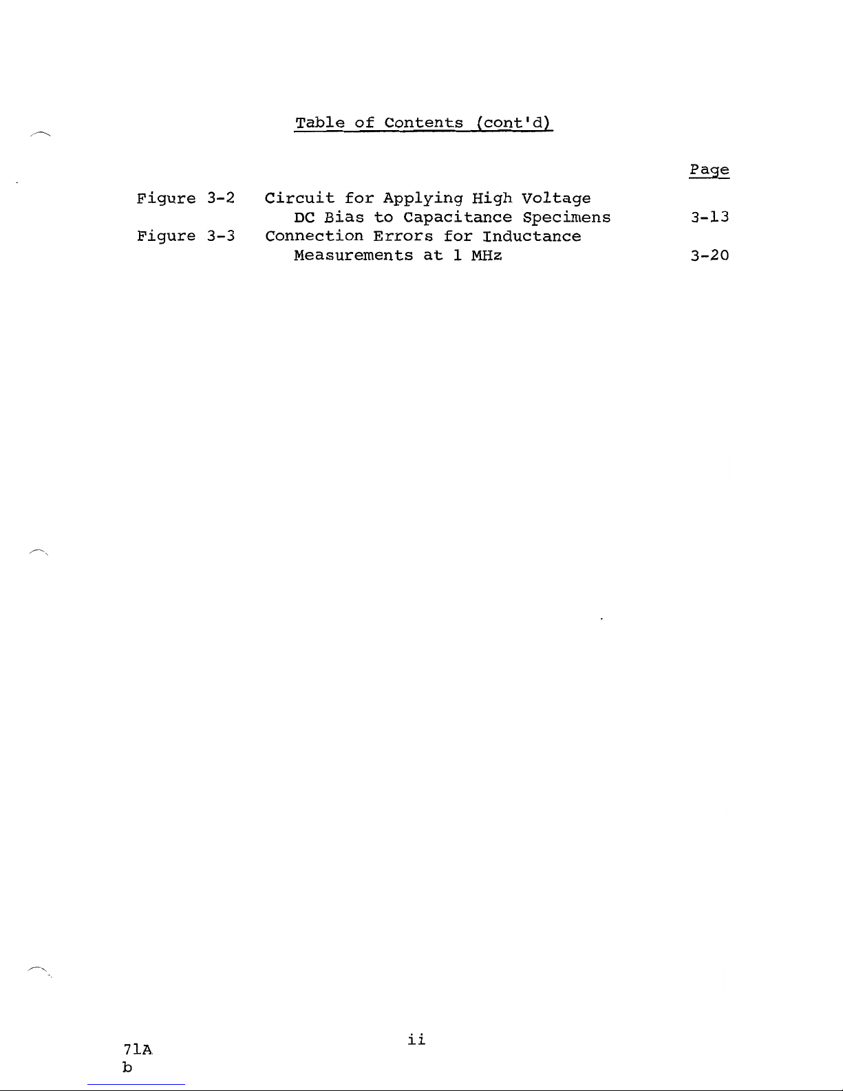
3.8.2
Connection
for
High
Voltage
DC
Bias
In
cases
where
a
dc
bias
voltage
of
greater
than
200
volts
i·s
required,
the
circuit
shown
in
Figure
3-2
may
be
used.
with
this
arrangement,
the
practical
limit
of
the
bias
that
can
be
applied
is
the
working
voltage
of
the
capacitor,
C.
3.9
Capacitance
Test
Signal
For
capacitance
measurements,
the
crystal
controlled
1
MHz
test
signal
is
fixed
at
15
millivolts
RMS
(±lmV).
It
is
not
adjustable,
and
any
attempts
to
alter
the
test
level
will
have
a
severe
effect
on
measuring
accuracy.
3.10
Capacitance
Calibration
Procedures
3.10.1
General
Calibration
of
the
Models
71A
and
7lAR*
should
be
checked
and
adjusted
using
both
high
Q
and
low
Q (Q=3)
tests.
It
is
not
advisable
to
check
and
adjust
calibration
at
either
the
upper
or
lower
limit
of
the
measuring
range;
hence
a
standard
of
100
pF
is
particularly
recommended.
In
any
case,
the
capacitance
standard
used
must
be
a
three-terminal
device
capable
of
operation
at
1 MHz.
The
Boonton
Electronics
Model
7l-1A
Capacitance
Standard
is
designed
specifically
for
use
with
the
Model
7lA
and
is
available
as
a
separate
accessory.
It
is
a
three-terminal
1
MHz
standard
which
is
adjusted
to
100
pF
(±.25%)
against
NOTE: *
The
Model
71-lA
Standard
capacitor
is
built
into
the
Model
71AR.
See
paragraph
3.10~4.
3-12
71A
Page 25

)
)
CJ'J
~
}>
CONNECTIONS
FOR
EXTERNAL
BIAS-7IA,7IAR,B7ICR
C
z
~200(CTEST)'
WITH
VOLTAGE
RATING>
E
NOTE:
LI03
MAY
BE
USED
FOR
1I. LI03
MAY
BE
ORDERED
FROM
L
,
&.
C1 TO
RESONATE @ IMHz.
Q",
L
1
>200K
(L
I
--150)/H;
0.>200)
BOONTON
ELECTRONICS
CORP.,
PART
NO.
400124;
PRICE
$1.50
RC
~
0.002
SECONDS.
EACH
i
MININU~
ORDER
$ \5.00.
L
,
"
,.-
-
C
2
I
I
,
~I
c
HI
C
1
I
\1
CURRE
N
/1
I
W
L1I4ITIN
II
RESISTO
~
w
I
1
BIAS
I
(
I
0
I
C
NODEL
~C
3.3M
C
TEST
I
SHORT
71A
"I
1
I
I
V
I
-=
;I. .
C
1
1
\\
/1
I
I
j
I
LO
I
-=
LI
L
_.
Figure
3-2
Dwg 830374B
Page 26

references
traceable
to
the
National
Bureau
of
Standards.
It
provides
a
particularly
convenient
means
for
checking
the
calibration
of
the
Model
71A
for
both
high
Q
and
low
0
(0=3)
measurements.
3.10.2
Calibration
Check
of
the
Model
71A
with
the
Model
71-1A
Standard
capacitor
(a)
Remove
all
cables
and
adapters
from
the
"TEST"
and
"STD"
terminals.
(b)
set
the
instrument
to
the
1
pF
range
and
adjust
the
"CaMP
ADJ"
control
as
explained
in
paragraph
3.3.2.2.
(c)
After
zeroing
the
instrument
on
the
1
pF
range,
switch
to
the
100
pF
range.
(d)
Plug
the
Model
7l-1A
into
the
test
terminals
of
the
Model
71A
and
observe
the
reading.
(e)
Depress
the
switch
on
the
case
of
the
Model
7l-lA
and
again
observe
the
reading.
If
a
reading
of
100
pF
is
obtained
for
both
readings
the
in-
strument
is
in
calibration.
Otherwise,
perform
the
follow-
ing
calibration
adjustments:
(a)
With
the
Model
7l-lA
connected
at
the
"TEST"
terminals
and
without
depressing
the
switch,
set
the
rear-panel
"CAL
1"
adjustment
for
a
reading
of
100
pF.
(b)
Depress
tpe
red
button
on
the
standard
capacitor,
reducing
its
0
to
3,
and
adjust
the
rear-panel
"CAL
2"
control
so
that
the
meter
again
reads
100
pF.
(c)
Release
the
switch.
If
the
instrument
still
reads
100
pF,
calibration
is
complete.
If
not,
repeat
Steps
a,
b,
and
c
upti1
the
instrument
reads
100
pF
for
both
tests.
3.10.3
calibration
Check
of
Model
7lA
with
a
Standard
other
Than
the
Model
71-1A
The
use
of
a
conventional
three-terminal
capaGitance
standard
for
low
Q
calibration
is
not
recommended
owing
to
the
un-
certainty
of
the
capacitance
ot
the
resistor
which
must
be
3-14
7lA
Page 27

added
for
the
low
Q
check.
However
..
if
it
is
necessary
to
use
this
method
..
it
is
suggested
that
the
capacitance
stand-
ard
be
in
the
order
of
100
pF
and
that
the
capacitance
of
the
resistor
be
assumed
to
be
0.5
pF.
This
also
has
the
advantage
of
requiring
a
resistor
of
sufficiently
low
value
(approximately
5000
ohms)
so
that
the
effective
1
Mc
resist-
ance
will
be
very
nearly
the
dc
value.
If
a
capacitance
standard
of
substantially
higher
value
is
used..
the
greater
correction
for
error
stemming
from
series
inductance
jeopardizes
the
accuracy
of
calibration
(see
paragraph
3.4.3.).
Prior
to
calibration
the
"eOMP
ADJ"
peaking
adjustment
should
be
performed
as
follows:
(a)
Attach
the
standard
to
the
"TEST"
posts
..
using
the
shortest
practical
lengths
of
coaxial
cable.
(b)
Set
the
"RANGE"
selector
to
the
lowest
value
on
which
..
by
adjustment
of
the
"e
ZERO"
control
..
a
reading
of
approximately
75%
of
full
scale
is
possible.
(c)
Adjust
the
"COMP
ADJ"
control
for
a
peak
reading.
(Readjust
the
"e
ZERO"
control
to
keep
deflections
on-scale
if
necessary).
(d)
Disconnect
the
coaxial
cable
from
the
"LO-"
test
terminal
and
zero
the
meter
using
the
"e
ZERO"
control.
Following
the
adjustment
of
the
"COMP
ADJ"
control
..
proceed
with
the
calibration
check
as
follows:
(a)
with
the
standard
connected
to
the
"TEST"
terminals
..
set
the
"RANGE
II
selector
to
produce
the
greatest
on-scale
deflection.
The
meter
should
read
the
value
of
the
standard.
(b)
Shunt
the
standard
with
the
resistor
to
simulate
a
Q
of
3.
The
meter
should
read
the
value
of
the
standard
plus
0.5
pF
(the
capacitance
of
the
shunt-
ing
resistor).
If
both
tests
yield
the
appropriate
values..
the
instrument
is
in
calibration.
Other-
wise,
the
following
calibration
adjustments
should
be
performed:
3-15
7lA
Page 28

(1)
With
the
shunting
resistor
removed~
set
the
rear
panel
IICAL
1"
adjustment
so
that
the
meter
reads
the
value
of
the
standard.
(2)
Replace
the
shunting
resistor
and
adjust
"CAL
2"
so
that
the
meter
reads
the
value
of
the
stand-
ard
plus
the
capacitance
of
the
resistor.
(3)
Remove
the
shunting
resistor.
If
the
meter
indicates
the
standard
value~
the
instrument
is
calibrated.
Otherwise~
repeat
steps
a~
b~
and
c
until
both
tests
yield
the
appropriate
value.
3.10.4
Calibration
Check
of
the
Model
71AR
with
the
Internal
Standard
Capacitor
(a)
Set
the
instrument
to
the
1
pF
range
and
adjust
the
"CaMP
ADJ"
control
as
explained
in
paragraph
3.3.2.2
with
no
specimen
at
the
"TEST"
terminals.
(b)
On
completing
the
IICOMP
ADJ"
peaking~
switch
to
the
100
pF
range.
(c)
with
the
Model
7lAR
set
to
the
100
pF
range
and
the
OPERATE
CAL
IleAL
2
selector
set
to
"CAL
l"~
note
the
meter
reading.
2
11
(d)
Switch
to
the
IICAL
position
(which
reduces
the
Q
of
the
standard
to
3)
and
again
check
the
reading.
(e)
If
the
indicator
reads
100
pF
for
both
tests~
the
instrument
is
in
calibration.
Otherwise
perform
the
following
calibration
adjustments:
1
11
(1)
Set
selector
to
the
IlCAL
position
and
adjust
the
IICAL
1"·
control
at
the
rear
panel
so
that
the
meter
reads
lOa
pF.
(2)
Set
selector
to
"CAL
2".
Adjust
the
2
11
IICAL
control
at
the
rear
panel
of
the
instrument
so
that
the
indicator
reads
100
pF.
(3)
Switch
back
to
IICAL
If
the
instrument
111.
still
reads
100
pF~
calibration
is
complete.
If
not,
repeat
Steps
a~
b~
and
c
until
the
instrument
reads
100
pF
on
both
tests.
3-16
71A
Page 29

3.11
Inductance
Measurements
3.11.1
General
with
the
"L/C"
selector
in
the
"L"
position
the
Models
7lA
and
7lAR
measure
two-terminal
inductance.
It
will
be
noted
that
with
the
"L"
position,
the
normal
resting
place
of
the
indicator,
with
no
specimen
connected
to
the
"INDUCTANCE"
terminals,
is
at
the
extreme
right,
above
full
scale;
it
moves
down
scale
only
when
a
specimen
of
measureable
value
for
that
range
is
placed
across
the
terminals.
3.12
Connections
for
Inductance
Measurement
Ipductance
should
be
connected
directly
to
the
"INDUCTANCE"
terminals.
Use
of
connecting
leads
will
introduce
errors
of
measurement
as
shown
in
Fig.
3.3.
3.13
Inductance
Zero
Check
The
Model
71A
can
be
quickly
checked
for
L
zero
by
placing
a
short
length
of
#22
copper
wire
tightly
across
the
"INDUCTANCE"
terminals,
with
the
"RANGE"
selector
set
at
l~.
The
reading
should
be
three-quarters
of
a
minor
scale
division
above
zero.
If
not,
the
"L
ZERO"
control
(center
adjustment
on
the
left
side
of
the
instrument)
should
be
adjusted
for
this
reading.
(NOTE:
The
controls
immediately
above
and
below
the
"L ZERO"
control
are
factory
adjustments
and
their
settings
should
not
be
disturbed.)
Once
adjusted
as
described
above,
the
Model
7lA
is
properly
set
for
all
inductance
ranges.
IMPORTANT
NOTE
The
"1000
pF
ZERO"
control
should
be
properly
set
(see
paragraph
3.4)
before
checking
the
inductance
zero
position.
The
"1000
pF
ZERO"
has
a
direct
in-
fluence
on
inductance
readings
and
once
set~
should
not
be
disturbed
during
the
course
of
measurement.
3-17
7lA
d
Page 30

3.14
DC
output
,
3.14.1
General
A
dc
analog
of
the
measured
capacitance
or
inductance
value
is
available
in
two
modes
(REC
and
DVM)
as
selected
by
con-
nections
at
the
rear
panel.
The
output
is
valuable
for
such
uses
as
application
to
a
recorder~
x-y
plotter~
digital
volt-
meter~
voltage
comparator~
etc.
Response
time
of
the
dc
output
is
less
than
10
milliseconds.
3.14.
2REC
Mode
By
connecting
to
the
"REC"
and
common
terminals,
the
output
for
all
ranges
varies
linearly
with
the
meter
reading
from
o
to
a
maximum
of
approximately
1.7
volts
(into
loads
of
10
megohms
or
greater).
3.14.3
DVM
Mode
Taking
the
output
from
the
"DVM"
and
common
terminals
pro-
vides
a
voltage
which
varies
from
0
to
100
millivolts
or
300
millivolts
for
full
scale
deflection~
depending
on
the
numerics
of
the
selected
range.
In
cases
where
the
output
is
used
with
a
digital
voltmeter
having
an
input
impedance
of
10
megohms
or
greater,
the
resistor
supplied
across
the
terminals
should
be
left
in
position.
For
digital
volt-
meters
having
an
input
impedance
of
1
megohm
this
resistor
should
be
removed.
If
the
input
resistance
of
the
DVM
is
less
than
1
megohm,
the
3:1
ratio
of
the
internal
attenuator
will
be
somewhat
in
error.
3.14.4
DVM
outEut
Adjustment
A
control
for
the
"DVM"
output
is
provided
on
the
rear
panel
to
permit
setting
a
digital
voltmeter
for
exact
agreement
with
a
standard
capacitor.
To
set
this
adjustment,
attach
a
standard
capacitor
that,will
produce
a
suitable
reading
(the
Model
7l-1A
Standard
Capacitor
is
convenient
for
this
purpose)
to
the
test
terminals
and
set
the
range
selector
to
the
appropriate
range.
(The
"CaMP
ADJ"
must
be
properly
adjusted
as
in
paragraph
3.10.2.)
with
the
digital
volt-
meter
properly
connected~
adjust
the
"DVM
ADJ"
control
so
that
the
digital
voltmeter
indicates
the
proper
value.
Once
adjusted
for
a
given
digital
voltmeter,
the
Model
71A
may
be
switched
from
range
to
range,
and
the
digital
volt-
meter
will
follow
correctly.
3-18
71A
d
Page 31

3.15
"METER
ON/OFF"
switch
In
cases
where
tests
are
being
made
at
high
speed
in
con-
junction
with
a
digital
vo1tmeter~
voltage
com~arator
or
other
external
monitor~
the
meter
should
be
switched
off
by
means
of
the
rear
panel
"METER-OFF"
switch
to
avoid
possible
interaction
caused
bya
small
counter-emf
from
the
moving
coil
of
the
meter.
Also,
this
avoids
damage
and
excessive
wear
of
the
movement.
Whether
the
meter
is
switched
on
or
off
has
no
bearing
on
the
accuracy
of
the
quiescent
value
of
the
dc
output.
NOTE:
In
the
Model
7lAR,
the
"METER-OFF"
switch
is
located
on
the
front
panel,
and
the
rear
panel
meter
switch
is
disabled.
3-19
71A
c
Page 32

CONNECTION
ERROR
RESULTING
FROM 3 INCH
LEADS
OJ-....I
I--'
>'
OF
NO.20
WIRE
SPACED
3/4
I
NCHES
APART
100
,
5
1\
\
2
'\
~
\.
~
10
'~
'I.
w
I
N
o
0::::
0
0::::
n::
w
~
o
0.1
5
2
5
2
O.lfLH
2
5
1.0fLH
""-
l\.
'I'\.
~
1\."
~
'I..
'I..
'I.....
ERROR
OWING
TO LEAD
INDU
CTANCE
(L%O.125~H)
2 5 2
10fLH
TOTAL
ERROR
/
l/.'
""
/
~
"
~
/
1/
;/
.I
I"'.
........
~
.A"
"--
./
-
"
/"
/
'1.,//
5 2
5
100fLH
1.1
V
V'
.IV
V
/
"
ERROR
OWING TO LEAD
C~PACITANCE
(C::::O.2 pF)
2
5
ImH
10mH
MEASURED
INDUCTANCE
Figure
3-3
Page 33

Page 34

Page 35

SECTION
IV
List of Replaceable Parts - Mode
Is
71
A-71
AR
Reference
Description
BEC
Part
No.
C101
Capacitor
0.1
}-IF
200 V
230,116
CI02
II
Yare
1.8-8.7
pF
275,138
C103
II
91
pF
500 V
200,035
II
CI03*
120
pF
500 V
200,002
11
CI04
Yare
3.8-50
pF
275,139
CI05
II
Yare
0.7-3
pF
279,109
II
CI06
0.033
flF
200 V
234,045
II
CI07
Yare
140
pF
275,104
.
CI08
Ir
0.02
}-IF
500 V
224,118
CI09
II
0.02
}-IF
500 V
224,118
C110*
II
97
pF
500 V
200,040
11
Clll
*
Yare
0.7-3.0
pF
279,109
11
C112*
Yare
0.1-3.0
pF
279,109
III
C113*
.022
flF
200 V
230,101
II
C201
0.01
}-IF
200 V
234,027
II
C202
0.02
}-IF
500 V
224,118
II
C203
O. 1
}-IF
25V
224,124
11
C204
0.02
}-IF
500 V
224,118
C205
II
150
pF
500 V
200,032
C206
II
0.02
tJF
500 V
224,118
C207
II
0.01
tJF
200 V
234,027
II
C208
O.
1
]JF
25 V
224,124
II
C209
0:02
]JF
500 V
224,118
C210
II
150
pF
500 V
200,032
C211
II
0.02
tJF
500 V
224,118
II
C212
0.01
J-lF
200 V
234,027
II
C213
91
pF
500 V
200,035
C214
II
Yare
7-45
pF
500 V
275,114
C215
II
0.02
}-IF
500 V
224,118
11
C216
150
pF
500 V
200,032
II
C217
0.02
jJF
500 V
224,118
II
C218
470
pF
300 V
200,028
II
C301
0.02
fJF
500 V
224,118
C302
0.02
jJF
500 V
224,118
C303
0.02
flF
500 V
224,118
C304
0.1
]JF
200 V
230,116
C305
430
pF
500 V
200,037
C306
430
pF
500 V
200,037
C307
0.022
]JF
200 V
230,101
II
C308
0.022
JlF
200 V
230,101
II
C401
56
pF
500
V
200,030
C402
11
250
pF
500 V
200,036
II
C403
0.02
J-IF
500 V
224,118
* Model
71
AR
only
PL-l
71
A-71
AR
Page 36

Reference
Description
BEC
Part
No.
C-40-4
C405
Capacitor
II
0.02
~F
0.02
J-lF
500 V
500 V
224,118
224,118
C406
II
0.02
llF
500 V
224,118
C407
1/
0.001
llF
500 V
224,114
C408
II
10
llF
6V
283,130
C409
II
20 llF
6V
283,153
C410
It
0.01
llF
200 V
234,027
C411
11
1
.0
llF
100 V
283,175
C412
II
25
J-lF
6V
283,177
C501
CS02
11
11
0.1
jJF
500
J-lF
200 V
3V
230,116
283,180
CS03
C504
II
II
0.02
jJF
0.02
J-lF
SOOV
500 V
224,118
224,118
C505
11
0.02J-lF
500 V
224,118
C601
C602
II
II
0.01
jJF
0.01
}-IF
600 V
600 V
234,077
234,077
C604
II
20/20
}-IF
450 V
283,100
R
101
Resistor
47 K
5%
1/2
W
301,127
RI02
II
169 Q
1%
1/4W
315,068
RI03
II
511
Q 1%
1/4W
315,080
RI04
RI05
II
II
1.65
K
4.99
K
1%
1%
1/4W
1/4W
315,092
315,103
RI06
II
16.9
K
1%
1/4W
315,117
RI6lV
RI08
II
II
53.6
K
178 K
1%
1%
1/4W
1/4W
315,133
315,141
RI09
II
6.65
K
1%
1/4W
315,107
R110
RIll
II
II
2.1 K
604
Q
1%
1%
1/4W
1/4W
315,095
315,082
R1l2
II
2050.
1%
1/4W
315,070
R113
II
60.4
Q
1%
1/4W
315,058
R114
II
19.6
Q
1%
1/4W
315,045
R115
II
100.
1%
1/4W
315,039
R116
R1l7
II
II
13
Q
220 K
1%
5%
1/4W
1/2W
315,042
301,143
R119*
II
4.7
K
5%
1/2W
301,103
R201
11
1 K
5%
1/2W
301/087
R202
II
510 K
5%
1/2
W
301/152
R203
R204
R205
R206
II
II
II
II
820 Q
100.
330 K
470
Q
5%
1%
5%
5%
1/2
W
1/4W
1/2
W
1/2
W
301,085
315,039
301/147
301,079
R207
R208
II
II
Factory Selected
1.21 K 1%
1/4W
315,089
R209
R2I0
II
II
1 K
510 K
5%
5%
1/2W
1/2W
301,087
301,152
* Model
71
AR
only
PL-2
71
A-71AR
c
Page 37

Reference
Description
BEe
Part
No.
R211
Resistor
820
Q
5%
1/2
W
301
1
085
11
R212
330 K
5%
1/2W
301,147
11
R213
470
Q
5%
1/2
W
301,079
II
R214
1
K
5%
1/2W
301,087
510 K
5%
1/2W
301,152
R215
II
II
R216
150
Q
1%
1/4W
315,067
R217
11
390 Q
5%
1/2W
301,077
11
R218
33 K
5%
1/2
W
301,123
R219
11
27 K
5%
1/2
W
301,121
J1
R220
470 n
5%
1/2W
301 1 079
R301
"
2K
5%
1/2W
301
,094
R302
II
470 Q 5%
1/2W
301
,079
R303
11
6.8
K
5%
1/2W
315,012
R304
Potentiometer
1 K
20%
311,100
R305
Resistor
6.8
K
5%
1/2W
315,012
R313
Resistor
470
n
5%
1/2W
301,079
R401
II
68
K
5%
1/2
W
301,131
II
R402
180 K
5%
1/2W
301,
141
R403
II
1l0n
5%
1/2
W
301,064
R404
11
470
Q 5%
1/2
W
301 1079
R405
"
33 K
5%
1
W
302,137
II
R406
33 K
5%
1
W
302,137
R407
Potentiometer
10 K
20% 2 W
311,102
R408
Resistor
43
K
5%
1/2
W
315,005
R409
II
160 K
5%
1/2
W
315,440
II
R410
160 K
5%
1/2W
315,440
R411
II
6.8
K
5%
1/2W
315,012
R413
II
20
K
5%
1!2W
301,118
R414
II
100 Q
1%
1/2
W
306,120
R415
Potentiometer
3K
20%
311,112
R416
Resistor
20
K
5%
1/2
W
301,118
R417
11
100 Q
1%
1/2
W
306,120
R418
1M
5%
1/2W
301,159
R419
33 K
5%
1/2
W
301,123
R420
130 K
5%
1/2
W
301,138
R421
2.7
K
5%
1/2
W
301,097
R422
2.2
M
5%
1/2
W
301,167
R423
51
K
5%
1/2
W
301,128
R424
20 K
5%
1/2W
301,118
R425
100
Q 1%
1/2
W
306,120
R426
lOOn
1%
1/2W
306,120
R427
II
20 K
5%
1/2
W
301,118
R428
II
2.2
M
5%
1/2W
301,167
R501
Potentiometers
5K
20%
311,101
thru
R514
Inc.
PL-3
71
A-71AR
r
Page 38

Reference
R515
Resistor
R516
II
R517
11
R518
II
R519
Potentiometer
R520
Resistor
R521
11
R522
11
R523
II
R604
11
R605
II
D201
Diode
0202
II
0203
JJ
0204
II
D301
II
0302
II
D401
11
0402
II
0403
II
0404
II
0405
II
0406
II
D501
II
FI01
Fuse
F601
(IllY
Models)
II
F60l
(230V
Models)
II
JI0l
Binding Posts
JI02
Binding Posts
J103
Connectors, Coaxial
J104
II
JI05
II
JI06
II
1101
Inductor
LlO2
II
1103
11
1104
II
71A-71AR
Description
1.3K
5%
12.1 K
1%
T.1M
5%
lOOK
5%
25 K
20%
20 K
1%
10
K
1%
Factory Selected
Factory Selected
1M
5%
4K
5%
IN251
lN251
1
N251
lN251
'IN914
1N914
1N251
'1N755A
'IN251
1
N251
'IN251
IN251
IN251
0.25A
AGC
0.5A
MDL
0.25A
MOL
0.1 to 0.21JH
0.5
to
1.2
pH
145
}JH
220
)JH
PL-4
BEC
Part
No.
1/2W
1/2W
1!2W
1/2W
2 W
1!2W
1/2W
301,090
315,413
301,160
315,023
311,115
315,418
315,411
1/2W
10 W
301,159
312,119
530,043
530,043
530,043
530,043
530,058
530,058
530,043
530,066
530,043
530,043
530,043
530,043
530,043
1/4
545,506
1/2
1/2
250 V
250 V
545,504
545,511
740,138
740,138
479,123
479,123
479,123
479,123
400,123
400,122
400,124
400,
1J
8
Page 39

Reference
~
L201
L202
L203
L204
L205
L206
L207
L208
L209
L210
Inductor
11
II
II
11
11
11
II
II
II
L301
11
L501
II
L601
Choke
M501
Meter
5101
5102
5103*
5501
Switch
u
\I
II
5601
II
TlOT
Transformer, Input
T201
Transformer,
Output
T301
T401
Transformer, Detector
..
Transformer,
Osc
ill
ator
T601
Transformer, Power
V201
V202
V203
Tube
II
11
V301
II
V401
V402
V60l
V602
Y401
II
II
II
II
Crystal
Description
BEC
Part
No.
1
pH
20%
400,120
1
mH
5%
400,095
105 to 200 pH
400,117
105 to 200
pH
400,117
220
pH
5%
400,118
220
pH
5%
400,118
ImH
5%
400,095
100
pH
20%
400,176
100
pH
200k
400,176
100
pH
20%
400,176
4.7
mH
5%
400,102
4.7
mH
5%
400,102
7Hi
50
rnA
440,001
0-100
pA
554,168
466,179
466,176
466,183
465,112
465,113
071,012
071,007
071,009
071,008
446,025
6CB6
526,6CB6
6CB6
526,6CB6
6CB6
526,6CB6
6CB6
526,6CB6
6BE6
526,6BE6
12M7
526,
12A'X.7
6X4
526,6X4
OA2
526,OA2
1 MHz
547,015
* Model
71
AR
only
PL-5
71A-71AR
c
Page 40

 Loading...