

Page 1

HUB INSTRUCTIONS
PART NUMBER 231793 SERVICE MANUAL 2003
Page 2

HUB INSTRUCTIONS
STANDARD
Front Hubs
Loose ball . . . . . . . . . . . . . . . . . . . . . . . . . . . . . . . . .2-3
Loose ball, semi-cartridge; Formula FCM . . . . . . .4-5
Cartridge bearing, alloy axle . . . . . . . . . . . . . . . . .6-7
Cartridge bearing, threaded alloy axle . . . . . . . . . .8-9
Rear hubs
Freehub body information (non-DT Swiss) . . . . . . . 11
Loose ball . . . . . . . . . . . . . . . . . . . . . . . . . . . . . . .12-13
Loose ball, double sealed (Formula FCM) . . . . . .14-15
Cartridge bearing . . . . . . . . . . . . . . . . . . . . . . . . .16-17
DT-SWISS
Comp series hubs
Introduction . . . . . . . . . . . . . . . . . . . . . . . . . . . . . . . 19
Comp front . . . . . . . . . . . . . . . . . . . . . . . . . . . . . .20-21
Comp rear . . . . . . . . . . . . . . . . . . . . . . . . . . . . . . .22-24
Pro series hubs
Introduction . . . . . . . . . . . . . . . . . . . . . . . . . . . . . . . 25
Pro front . . . . . . . . . . . . . . . . . . . . . . . . . . . . . . . .26-27
Pro rear . . . . . . . . . . . . . . . . . . . . . . . . . . . . . . . . .28-31
Please note: Many sections of this manual must be
read in their entirety before performing procedures.
In some cases, revised or updated information may
be available on the Bontrager wheelworks website at
www.bontrager.com.
If you cannot find the information you need to service
Bontrager wheels, please contact a technical service
representative.
Copyright Trek Bicycle Corporation 2002
All rights reserved
2003 Bontrager Service Manual
1
Page 3
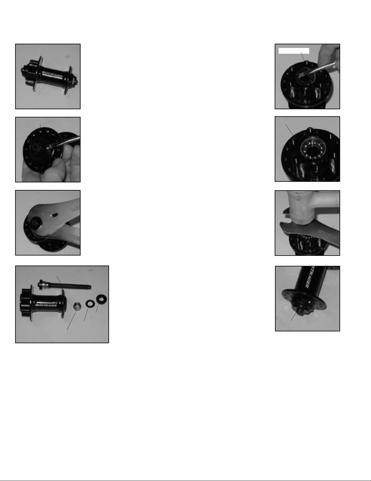
Front hubs- Loose ball
Bontrager Superstock, Superstock Disc, Select ATB, Select ATB Disc, Select Road, and Select Hybrid front wheels;
plus Bontrager Comp II front hub
Recommended tools
13mm cone wrench
17mm cone wrench
Small slot screwdriver
Hammer (soft faced)
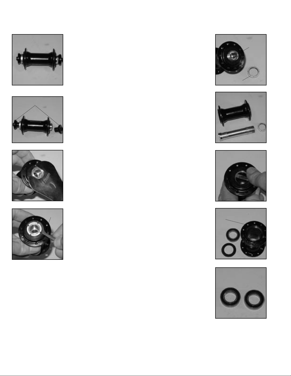
DISASSEMBLY
Hub parts and names are referenced on next page.
Remove the axle
Fig. 1A
External seal
Fig. 2A
Fig. 3A
Axle
Ball cone
Fig. 4A
Clean and inspect the parts
1. Use solvent to completely remove all old grease and
debris from the hub, axle, and axle parts.
2. Inspect the bearing running surfaces of both the
ball cones and the ball cups (inside the hub). Replace any
cones. If the cups are worn, replace the hub shell.
1. Remove external seals
(Fig. 2A) with a screwdriver. Be
careful not to tear or mar the
rubber.
2. On one side (either) of the
hub place a 13mm cone wrench
on the ball cone. Place a 17mm
cone wrench on the end nut (Fig.
3A). Loosen the end nut.
3. Remove the end nut,
washer, and ball cone from the
axle (Fig. 4A).
4. Slide the axle, with the
other end nut, washer, and ball
cone still attached, out of the
hub (Fig. 4A).
5. Gently insert a thin
screwdriver blade under the
shell shield (Fig. 5A) and lift to
remove the shield from the hub.
Pry off the shell shields from
both sides of the hub.
6. If inspection
shows it necessary,
remove the other end
nut and ball cone.
End nut
Washer
ASSEMBLY
Shell shield
1. Place eleven 3/16” balls in
the ball cup on one side of the hub.
2. Place the shell shield, with
its sharp edges facing out (Fig.
6A), into the hub. The shell shield
is a press fit, so must be tapped
lightly to fully seat. Lay a cone
wrench over the shell shield and
tap the wrench with a hammer
(Fig. 7A) to protect the shield
and ensure that it is flush with
Bearings in bearing cup
the shell.
3. Repeat Assembly steps 1-2
for the other side of the hub.
4. Tighten the end nut
against the ball cone on the axle.
Hold the ball cone with a 13mm
cone wrench on the axle flats
while turning the end nut with a
17mm cone wrench.
5. Insert the axle through the
hub from either side.
6. Thread the ball cone, washer, and end nut onto the axle in
that order. The serrated surface
of the end nut faces out.
7. Hold the ball cone with a
13mm cone wrench and tighten
the end nut with a 17mm cone
wrench.
8. Check the bearing adjustment by turning the axle with
your fingers. The axle should
spin smoothly without binding or
feeling gritty. There should be no
lateral play of the axle in the hub.
Readjust the hub as necessary,
and re-lock the end nut.
9. Install the external seals,
and apply grease where the seals
Seal not seated
contact the hub shell and axle
parts. Make sure the seals properly seal against both the end nut and the hub shell. There
should be a smooth transition from seal to sealing surface.
An improperly installed seal (Fig. 8A) will allow rapid contamination of the bearings.
After completing assembly of the hub, check its function by spinning the axle with your fingers. It
should rotate freely without irregular friction. A small amount of lateral play is acceptable if the play is
eliminated when the wheel is installed with the quick release properly closed.
Fig. 5A
Fig. 6A
Fig. 7A
Fig. 8A
Lubricate bearings and threads
1. Lubricate the threads on the axle with Wrench
Force™ synthetic grease, or a similar product.
2. Place a bead of grease all the way around each ball
cup, sufficient to hold the balls.
2
2003 Bontrager Service Manual
Page 4
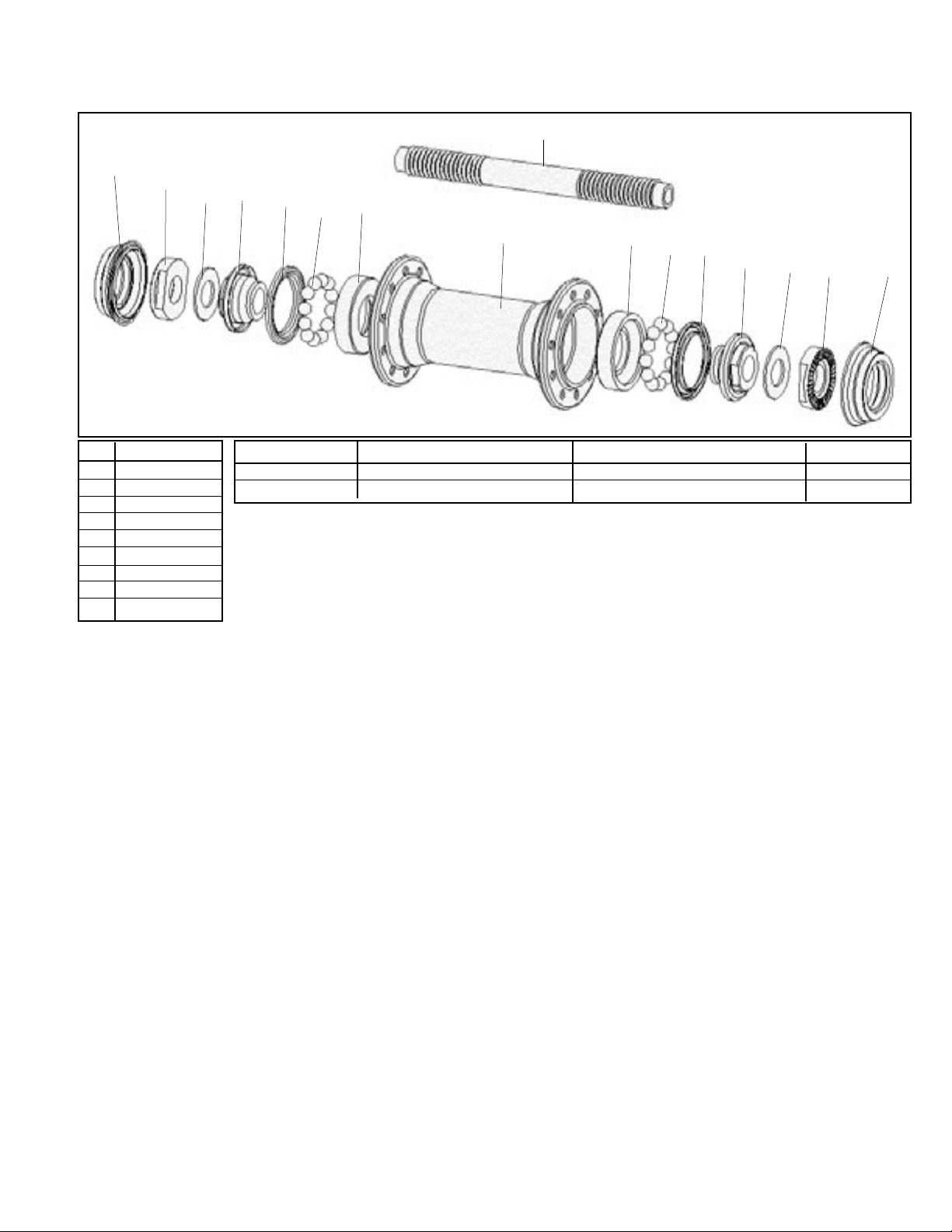
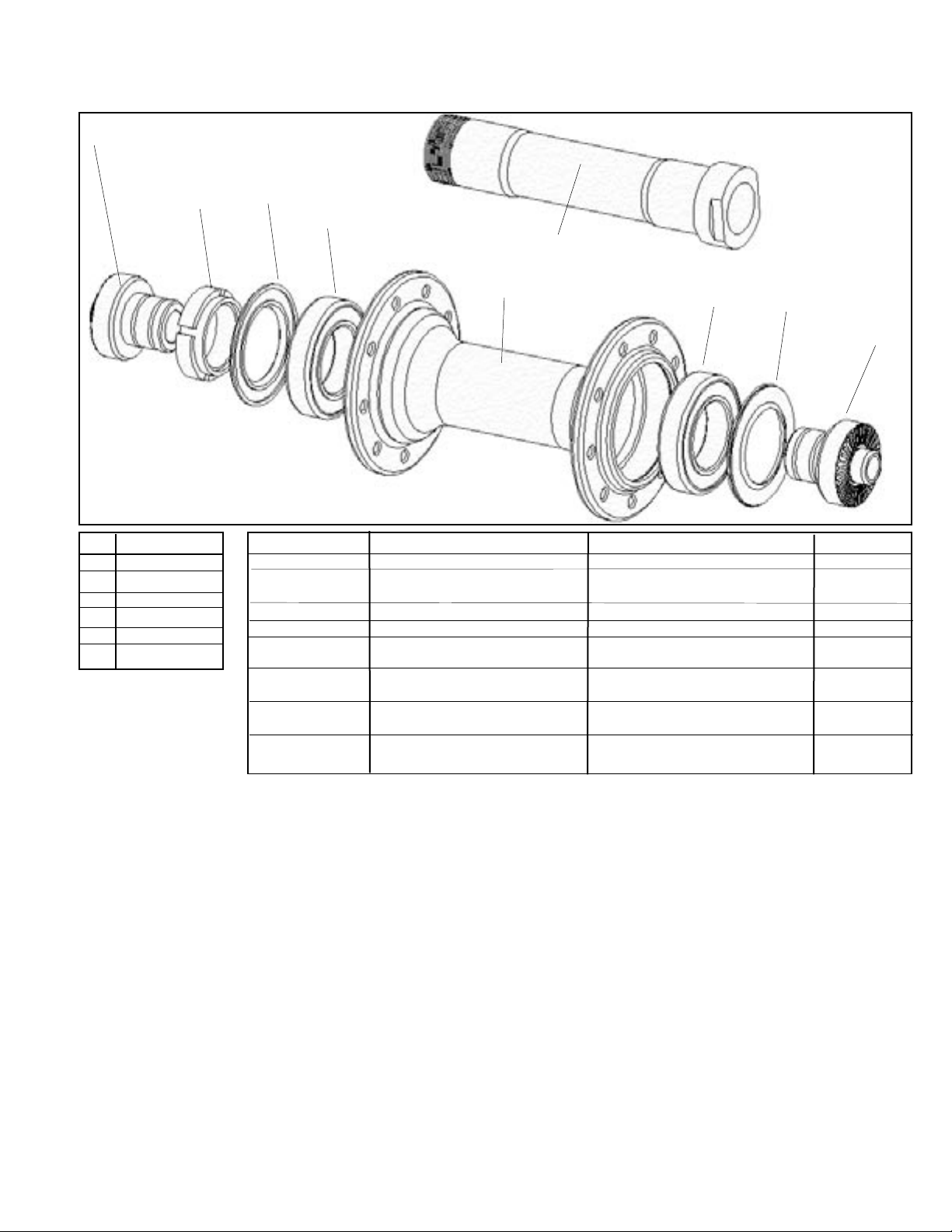
Exploded view and Parts list
9
1
2
4
3
5
7
6
8
7
6
5
4
3
2
1
Pos Description
1 External seal
2 End nut
Description Model year Model for Parts included (qty) TCG Part #
Axle set 99/00/01/02 all 1(2), 4(2), 3(2), 9 68257
Locknut set 99/00/01/02 all 2(2) 68543
3 Washer
4 Ball cone
5 Shell shield
6 Ball bearings
7 Ball cup
8 Hub shell
9 Axle
1999 Bontrager Comp II
O.L.D. . . . . . . . . . . . . . . . . . . . . . . . . . . . . . . . . . . . . . . . . . . . . . . . 100 mm
Spoke hole quantity . . . . . . . . . . . . . . . . . . . . . . . . . . . . . . . . . . . . . . 32°
Spoke hole P.C.D. . . . . . . . . . . . . . . . . . . . . . . . . . . . . . . . . . . . . 38.0 mm
Q.R. rod outer diameter . . . . . . . . . . . . . . . . . . . . . . . . . . . . . . . . . 6 mm
2000/2001/2002/2003 Superstock
O.L.D. . . . . . . . . . . . . . . . . . . . . . . . . . . . . . . . . . . . . . . . . . . . . . . . 100 mm
Spoke hole quantity . . . . . . . . . . . . . . . . . . . . . . . . . . . . . . . . . . . . . . 24°
Spoke hole P.C.D. . . . . . . . . . . . . . . . . . . . . . . . . . . . . . . . . . . . . 38.0 mm
Q.R. rod outer diameter . . . . . . . . . . . . . . . . . . . . . . . . . . . . . . . . . 5 mm
2002/2003 Superstock Disc, Select ATB Disc
O.L.D. . . . . . . . . . . . . . . . . . . . . . . . . . . . . . . . . . . . . . . . . . . . . . . . 100 mm
Spoke hole quantity . . . . . . . . . . . . . . . . . . . . . . . . . . . . . . . . . . . . . . 28°
Spoke hole P.C.D. . . . . . . . . . . . . . . . . . . . . . . . . . . . . . . . . . . . . 58.0 mm
Q.R. rod outer diameter . . . . . . . . . . . . . . . . . . . . . . . . . . . . . . . . . 5 mm
Disc rotor spacing . . . . . . . . . . . . . . . . . . . . . . . . . . . . . . . . . . . . 10.5 mm
Rotor BCD . . . . . . . . . . . . . . . . . . . . . . . . . . . . . . . . . . . . . . . . . . 44.0 mm
2002/2003 Select ATB
O.L.D. . . . . . . . . . . . . . . . . . . . . . . . . . . . . . . . . . . . . . . . . . . . . . . . 100 mm
Spoke hole quantity . . . . . . . . . . . . . . . . . . . . . . . . . . . . . . . . . . . . . . 24°
Spoke hole P.C.D. . . . . . . . . . . . . . . . . . . . . . . . . . . . . . . . . . . . . 38.0 mm
Q.R. rod outer diameter . . . . . . . . . . . . . . . . . . . . . . . . . . . . . . . . . 5 mm
2002/2003 Select Road, Hybrid
O.L.D. . . . . . . . . . . . . . . . . . . . . . . . . . . . . . . . . . . . . . . . . . . . . . . . 100 mm
Spoke hole quantity . . . . . . . . . . . . . . . . . . . . . . . . . . . . . . . . . . . . . . 20°
Spoke hole P.C.D. . . . . . . . . . . . . . . . . . . . . . . . . . . . . . . . . . . . . 38.0 mm
Q.R. rod outer diameter . . . . . . . . . . . . . . . . . . . . . . . . . . . . . . . . . 5 mm
2003 Bontrager Service Manual
3
Page 5
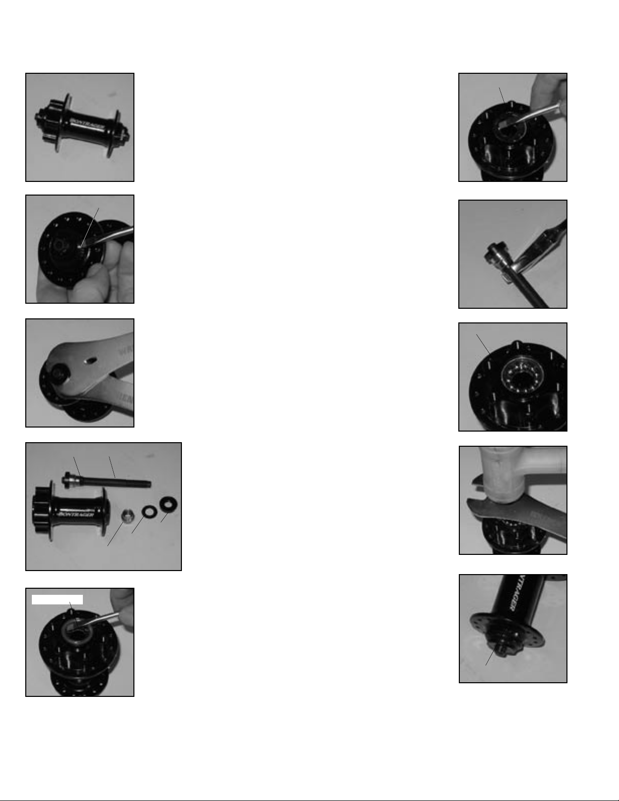
Front hubs- Loose ball, semi-cartridge; Formula FCM
'99, 2000, 2001 Bontrager Race, Race Disk front wheels
Recommended tools
13mm cone wrench
17mm cone wrench
Adjustable wrench
Hammer (soft faced)
Small slot screwdriver
DISASSEMBLY
Hub parts and names are referenced on next page.
Fig. 1B
External seal
Fig. 2B
Fig. 3B
Collar
Fig. 4B
Shell shield
Fig. 5B
Axle
Ball cone
ning surfaces of both the ball cones and the ball cups
(inside the hub). Replace any worn parts.
Note: If the ‘fixed’ ball cone is worn, the axle assembly (axle and ball cone) must be replaced.
Remove the axle
1. Remove external seals
(Fig. 2B) with a screwdriver. Be
careful not to tear or mar the
rubber.
2. On one side of the hub
(usually left), the cone is locked
against a collar on the axle (Fig.
4B). On the other side, place a
13mm cone wrench on the ball
cone. Place a 17mm cone wrench
on the end nut (Fig. 3B). Loosen
the end nut.
3. Remove the end nut, washer, and ball cone from the axle
(Fig. 4B).
4. Slide the axle, with the
other end nut, washer, and ball
cone still attached, out of the hub.
6. Gently insert a thin
screwdriver blade between the
shell shield (Fig. 5B) and bearing seal (Fig. 6B). Pry off the
shell shields from
both sides of the hub.
Do not attempt to pry
off both shield and
seal at the same time
as you may damage
the bearing seal.
End nut
Washer
7. Gently pry off
the bearing seals (Fig.
6B) from both sides of
the hub.
8. If inspection
shows it necessary,
remove the other end nut. Hold
the axle by the wrench flats
(Fig. 7B) while turning the end
nut with a 17mm cone wrench.
Clean and inspect the parts
1. Use solvent to completely
remove all old grease and debris
from the hub, axle, and axle
parts.
2. Inspect the bearing run-
Lubricate bearings and threads
Bearing seal
1. Lubricate the threads on
the axle with Wrench Force™ synthetic grease, or a similar product.
2. Place a bead of grease all
the way around each ball cup,
sufficient to hold the balls.
ASSEMBLY
1. Place eleven 3/16” balls in
the ball cup on one side of the
hub (Fig. 8B).
2. Place the bearing seal,
with the lettered side facing out,
into the ball cup.
3. Place the shell shield, with
its sharp edges facing out, into
the hub. The shell shield is a press
fit, so must be tapped lightly to
fully seat. Lay a cone wrench
over the shell shield and tap the
wrench with a hammer (Fig. 9B)
Bearings in ball cup
to protect the shield and ensure
that it is flush with the shell.
4. Repeat Assembly steps 1-3
for the other side of the hub.
5. Tighten the end nut
against the fixed ball cone
(attached to axle). Hold the axle
with an adjustable wrench on the
axle flats while turning the end
nut with a 17mm cone wrench.
6. Insert the axle through the
hub from either side.
7. Thread the ball cone, washer, and end nut onto the axle in
that order. The serrated surface
of the end nut faces out.
8. Hold the ball cone with a
13mm cone wrench and tighten
the end nut with a 17mm cone
wrench.
9. Check the bearing adjustment by turning the axle with
your fingers. The axle should
spin smoothly without binding or
feeling gritty. There should be no
lateral play of the axle in the hub.
Readjust the hub as necessary,
and re-lock the end nut.
10. Install the external seals.
Make sure the seals properly seal
Seal not seated
against both the end nut and
the hub shell. There should be a
smooth transition from seal to sealing surface. An improperly installed seal (Fig. 10B) will allow rapid contamination of the bearings.
After completing assembly of the hub, check its function by spinning the axle with your fingers. It
should rotate freely without irregular friction. A small amount of lateral play is acceptable if the play is
eliminated when the wheel is installed with the quick release properly closed.
Fig. 6B
Fig. 7B
Fig. 8B
Fig. 9B
Fig. 10B
4
2003 Bontrager Service Manual
Page 6
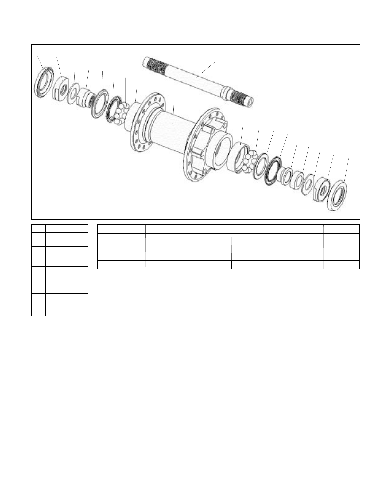
Exploded view and Parts list
1
Note:
Rotor adapter for disc hubs not shown
Rotor spacing varies by model year, see details below.
2
3
4
5
6
10
7
8
9
8
7
6
5
12
11
3
2
1
Pos Description
1 External seal
2 End nut
3 Washer
4 Adjust cone
5 Shell shield
Description Model year Model for Parts included (qty) TCG Part #
Axle set 99/00/01 all 10, 4, 2, 5(2), 11, 6(2), 3(2) 68524
Locknut set 99/00/01 all 2(2) 68527
Rotor adapter 99/00 Hayes, RST Not shown 991083
w/screws
Disc bolt set 99/00 all Not shown 991153
6 Bearing seal
7 Ball bearings
8 Ball cup
9 Hub shell
10 Axle
11 Spacer
12 Ball cone
1999 Race
O.L.D. . . . . . . . . . . . . . . . . . . . . . . . . . . . . . . . . . . . . . . . . . . . . . . . 100 mm
Spoke hole quantity . . . . . . . . . . . . . . . . . . . . . . . . . . . . . . . . . . . . . . 24°
Spoke hole P.C.D. . . . . . . . . . . . . . . . . . . . . . . . . . . . . . . . . . . . . 38.0 mm
Q.R. rod outer diameter . . . . . . . . . . . . . . . . . . . . . . . . . . . . . . . . . 6 mm
1999/2000 Race Disk
O.L.D. . . . . . . . . . . . . . . . . . . . . . . . . . . . . . . . . . . . . . . . . . . . . . . . 100 mm
Spoke hole quantity . . . . . . . . . . . . . . . . . . . . . . . . . . . . . . . . . . . . . . 28°
Spoke hole P.C.D., right . . . . . . . . . . . . . . . . . . . . . . . . . . . . . . 45.0 mm
Spoke hole P.C.D., left . . . . . . . . . . . . . . . . . . . . . . . . . . . . . . . 58.0 mm
Q.R. rod outer diameter . . . . . . . . . . . . . . . . . . . . . . . . . . . . . . . . . 6 mm
Disc rotor spacing . . . . . . . . . . . . . . . . . . . . . . . . . . . . . . . . . . . . 16.0 mm
Rotor BCD . . . . . . . . . . . . . . . . . . . . . . . . . . . . . . . . . . . . . . . . . . 44.0 mm
2001 Race Disk
O.L.D. . . . . . . . . . . . . . . . . . . . . . . . . . . . . . . . . . . . . . . . . . . . . . . . 100 mm
Spoke hole quantity . . . . . . . . . . . . . . . . . . . . . . . . . . . . . . . . . . . . . . 28°
Spoke hole P.C.D., right . . . . . . . . . . . . . . . . . . . . . . . . . . . . . . 45.0 mm
Spoke hole P.C.D., left . . . . . . . . . . . . . . . . . . . . . . . . . . . . . . . 58.0 mm
Q.R. rod outer diameter . . . . . . . . . . . . . . . . . . . . . . . . . . . . . . . . . 6 mm
Disc rotor spacing . . . . . . . . . . . . . . . . . . . . . . . . . . . . . . . . . . . . 10.5 mm
Rotor BCD . . . . . . . . . . . . . . . . . . . . . . . . . . . . . . . . . . . . . . . . . . 44.0 mm
2000/2001 Race
O.L.D. . . . . . . . . . . . . . . . . . . . . . . . . . . . . . . . . . . . . . . . . . . . . . . . 100 mm
Spoke hole quantity . . . . . . . . . . . . . . . . . . . . . . . . . . . . . . . . . . . . . . 24°
Spoke hole P.C.D. . . . . . . . . . . . . . . . . . . . . . . . . . . . . . . . . . . . . 38.0 mm
Q.R. rod outer diameter . . . . . . . . . . . . . . . . . . . . . . . . . . . . . . . . . 5 mm
2003 Bontrager Service Manual
5
Page 7
Front hubs- Cartridge bearing, alloy axle
2002/2003 Bontrager Race, Race Disc front wheels
Fig. 1C
Fig. 2C
Fig. 3C
Fig. 4C
End caps
Axle nut
Recommended tools
17mm cone wrench
Special hook spanner
Hammer and broad punch
Bearing removal tool
Bearing press
DISASSEMBLY
Hub parts and names are referenced on next page.
Remove the axle
1. Remove axle end caps
(Fig. 2C) by sliding them out of
the axle with your fingers.
2. Hold the axle with a
17mm cone wrench (Fig. 3C)
while loosening the axle nut
with the special hook spanner
(Fig. 4C).
3. Partially unthread the
axle nut (Fig. 5C) until it
slightly protrudes past the end
of the axle.
4. Tap the axle nut with a
soft-faced hammer until the axle
slides through the opposite bearing. Once loose, the axle should
come out with your fingers.
5. Remove the axle nut, and
extract the axle (Fig. 6C).
6. Gently insert a thin screwdriver blade between the bearing
seal (Fig. 7C) and bearing. Pry
off the bearing seals from both
sides of the hub.
7. Insert a bearing removal
tool into the bearing. Place a
blunt punch through the hub
and against the bearing removal
tool. Tap the punch with the
hammer to drive the bearing out
of the hub (Fig. 8C). Repeat for
the other bearing.
ASSEMBLY
1. Press a bearing into the
hub with a bearing press.
Note: the black seal faces out (Fig. 9C).
2. Press the second bearing
with the bearing press.
3. Place the bearing seals
into the hub with the lettered
surface facing out.
6. Insert the axle through the
hub from either side.
7. Thread the axle nut onto
the axle.
8. Hold the axle with a 17mm
cone wrench and tighten the axle
nut with the special hook spanner until finger tight.
Do not over-tighten the axle nut. The axle should turn freely
with no lateral play in the hub shell.
9. Press the axle end caps
into both ends of the axle.
After completing assembly of the hub, check its function by
spinning the axle with your fingers. It should rotate freely
without irregular friction. A small amount of lateral play
is acceptable if the play is eliminated when the wheel is
installed with the quick release properly closed.
Axle
Axle nut
Fig. 5C
Fig. 6C
Fig. 7C
Bearing
seat
Fig. 8C
Clean and inspect the parts
1. Wipe old grease or debris from the hub bearing
seats.
2. Normally, bearings are not re-used. If you are reinstalling an old bearing, wipe off any grease or debris
from both the inner and outer surfaces.
Do not use solvent on the bearing, as the solvent will
contaminate the grease. This may cause bearing failure.
Lubricate bearings and threads
1. Lubricate the threads on the axle with Wrench
Force™ synthetic grease, or a similar product.
2. Lightly grease the inner and outer surfaces of
each bearing.
6
2003 Bontrager Service Manual
Fig. 9C
Page 8
Exploded view and Parts list
1
2
Note:
Rotor adapter for disc hubs not shown
Rotor spacing varies by model year, see details below.
Pos Description
1 End cap
2 Adjustable nut
3 Seal
4 Bearing
5 Hub shell
6 Axle
3
Description Model year Model for Parts included (qty) TCG Part #
Seal 99/00/01 all 3(2) 68261
Bearing 99/00/01 all 4(2) 68262
#6903
Axle set 99/00/01 all 6, 4(2) 68263
Adjustable nut 99/00/01 all 2 68264
End cap, 99/00/01/02 all 1(2) 211645
20.5mm O..D.
Rotor adapter 99/00 Hayes, RST Not shown 991083
w/screws
Disc bolt set 99/00 all Not shown 991153
4
6
5
4
3
1
Special 99/00/01/02 all Not shown, see Fig. 4C 68259
hook spanner
2002 Race
O.L.D. . . . . . . . . . . . . . . . . . . . . . . . . . . . . . . . . . . . . . . . . . . . . . . . 100 mm
Spoke hole quantity . . . . . . . . . . . . . . . . . . . . . . . . . . . . . . . . . . . . . . 24°
Spoke hole P.C.D. . . . . . . . . . . . . . . . . . . . . . . . . . . . . . . . . . . . . 42.0 mm
Q.R. rod outer diameter . . . . . . . . . . . . . . . . . . . . . . . . . . . . . . . . . 5 mm
2002 Race Disk
O.L.D. . . . . . . . . . . . . . . . . . . . . . . . . . . . . . . . . . . . . . . . . . . . . . . . 100 mm
Spoke hole quantity . . . . . . . . . . . . . . . . . . . . . . . . . . . . . . . . . . . . . . 28°
Spoke hole P.C.D., right . . . . . . . . . . . . . . . . . . . . . . . . . . . . . . 45.0 mm
Spoke hole P.C.D., left . . . . . . . . . . . . . . . . . . . . . . . . . . . . . . . 58.0 mm
Q.R. rod outer diameter . . . . . . . . . . . . . . . . . . . . . . . . . . . . . . . . . 5 mm
Disc rotor spacing . . . . . . . . . . . . . . . . . . . . . . . . . . . . . . . . . . . . 10.5 mm
Rotor BCD . . . . . . . . . . . . . . . . . . . . . . . . . . . . . . . . . . . . . . . . . . 44.0 mm
2003 Bontrager Service Manual
7
Page 9
2003 Bontrager Service Manual
Needs photos and text
Front hubs- Cartridge bearing, threaded alloy axle
2002/2003 Bontrager Race Lite Road front wheels
Recommended tools
17mm cone wrench (2)
Hammer and broad punch
Bearing press
DISASSEMBLY
Hub parts and names are referenced on next page.
Remove the axle
1. Remove one of the thread-
Fig. 1H
Fig. 2H
second bearing from the axle. To do this, clamp the
middle of the axle, loosen the end cap, and remove it.
Support the bearing and tap the axle out with a softfaced hammer.
ed axle end caps (Fig. 2H) by
loosening with the pair of 17mm
cone wrenches.
2. With one end cap
removed, drive the axle from
the hub shell with a soft-faced
hammer.
3. Place a broad punch
through the hub, and tap the
punch with a hammer to drive
the second bearing (Fig. 3H),
with its seal, from the hub.
4. If needed, remove the
ASSEMBLY
1. Press a new bearing onto
the axle with a bearing press.
Note: the black seal faces out (Fig. 4H).
2. Place the hub seal onto the
axle, and thread on the axle end
cap. Clamp the middle of the axle
and tighten the axle end cap with
the 17mm cone wrench.
3. Press the bearing, with the
axle attached, into the hub.
4. Press the second bearing into the hub.
Note: the black seal faces out (Fig. 4H).
5. Place the hub seal over the bearing, and press into
the hub shell.
6. Thread on the second axle end cap, and tighten with
the 17mm cone wrench.
Do not over-tighten the axle nut. The axle should turn freely with no lateral play in the hub shell.
Fig. 4H
Clean and inspect the parts
1. Wipe old grease or debris from the hub bearing
seats.
2. Normally, bearings are not re-used. If you are reinstalling an old bearing, wipe off any grease or debris
from both the inner and outer surfaces.
Do not use solvent on the bearing, as the solvent will
contaminate the grease. This may cause bearing failure.
Lubricate bearings and threads
1. Lubricate the threads on the axle with Wrench
Force™ synthetic grease, or a similar product.
2. Lightly grease the inner and outer surfaces of
each bearing.
8
Fig. 3H
2003 Bontrager Service Manual
Page 10

Exploded view and Parts list
1
Pos Description
1 End nut
2 Seal
3 Bearing
4 Hub shell
5 Axle
2
3
5
4
Description Model year Model for Parts included (qty) TCG Part #
Seal 02 all 2(2) 221468
Bearing 02 all 3(2) 73335
#6000
Axle set 02 all 1(2), 2(2), 3(2), 5 221470
End nut 02 all 1(2) 221467
Axle 02 all 5 221469
3
2
1
2002/2003 Race Lite Road
O.L.D. . . . . . . . . . . . . . . . . . . . . . . . . . . . . . . . . . . . . . . . . . . . . . . . 100 mm
Spoke hole quantity . . . . . . . . . . . . . . . . . . . . . . . . . . . . . . . . . . . . . . 20°
Spoke hole P.C.D. . . . . . . . . . . . . . . . . . . . . . . . . . . . . . . . . . . . . 38.0 mm
Q.R. rod outer diameter . . . . . . . . . . . . . . . . . . . . . . . . . . . . . . . . . 5 mm
2003 Bontrager Service Manual
9
Page 11

Freehub body information (non-DT Swiss)
FREEHUB BODY RUNNING CHANGE
Bontrager rear hubs use an unique freehub body that
in some cases has encountered removal issues. In these
cases, a high amount of torque is necessary to remove or
install the freehub body attachment bolt.
To resolve this problem a running change was made
to the 2001 product line. The older, direct contact style
of freehub body has been replaced with a splined freehub
body attachment. This splined attachment requires less
bolt torque. Since it is a running change, the following
information is necessary to identify which freehub body
is on a wheel.
If there is a date code stamped on the freehub body
it probably uses a splined attachment. If there is no date,
it is a threaded attachment. After May 2000, both styles
of freehub bodies (both attachment types) will have this
date mark.
These different styles of freehub bodies are not interchangeable.
Identification of freehub bodies
Threaded freehub body
CNC line
Fig. 1
With the older, threaded
freehub body, there are two
identifiers. First, there is a
CNC machine line approximately
10mm from the outside end of
the freehub body (Fig. 1).
Second, the thread-attached
freehub body is designed to be
removed with a 12mm allen
wrench.
INSTALLATION AND REMOVAL
If the freehub body is worn or damaged, replace it.
Removing the freehub body
1. Follow the Disassembly
instructions for the hub. Remove
the axle, and then the right side
bearings.
2. Determine the correct size
of allen wrench to engage the
freehub body attachment bolt.
3. Unthread the bolt in a
counter-clockwise direction
(standard threading).
Installing the freehub body
1. Carefully clean the mating surfaces and threads of
the freehub body, hub shell, and attachment bolt.
2. Lubricate the threads of the attachment bolt with
Wrench Force™ synthetic grease, or a similar product.
3. Carefully engage the threads of the freehub body
attachment bolt into the hub shell. The bolt is steel, and
the hub is aluminum, so cross-threading the bolt will
result in destruction of the hub shell.
4. With the new splined freehub engagement, make
sure the splines are aligned as you tighten the attachment
bolt.
For the older, threaded style freehub body, tighten the
freehub attachment bolt to 350 lb•in (40Nm).
For the newer, splined design, tighten the freehub
attachment bolt to 400 lb•in (45.2 Nm).
Fig. 4
Splined freehub body
The newer, splined attachment (Fig. 2) freehub body has
no CNC line. Further, it is
designed to use an 11mm allen
wrench for removal. A special
adapter (TCG #211338) is made
which attaches to an 8mm allen
wrench to fit the 11mm allen
head of the freehub attachment
Fig. 2
bolt (Fig. 3).
In addition, as a running
change the new hub bodies will
include a 6-digit part number
embossed on the outside of the
hub shell where it is plainly visible. All hubs with the part number visible use the splined freehub body.
Fig. 3
Description TCG Part #
Freehub tool, 211338
11mm adapter
2003 Bontrager Service Manual
11
Page 12

Rear hubs- Loose ball
Bontrager Superstock, Superstock Disc, Select ATB, Select Road, Select Hybrid wheels, plus Bontrager Comp II rear hub
Recommended tools
(2) 15mm cone wrench
Adjustable wrench
Hammer (soft faced)
Small slot screwdriver
DISASSEMBLY
Fig. 1D
Fig. 2D
Fig. 3D
Axle
End
nut
Small
washer
Large
washer
Fig. 4D
Spacer
removal and installation instructions.
When overhauling the hub bearings, it is usually not necessary to remove the freehub body.
Fig. 5D
12
Hub parts and names are referenced on next page.
Remove the axle
1. Remove external seals
with your fingers or a screwdriver (Fig. 2D). Be careful not
to tear or mar the rubber.
2. On the left side (non-drive)
of the hub place a 15mm cone
wrench on the ball cone. Place a
15mm cone wrench on the end
nut (Fig. 3D). Loosen the end
nut.
4. Remove the end nut, large
washer, spacer, small washer,
and ball cone from the axle (Fig.
4D).
5. Slide the axle, with the
other end nut, washer, and ball
cone still attached, out of the hub.
6. Insert a thin screwdriver
blade under the shell shield (Fig.
5D) and pry off the shell shield
from the left side of the hub.
8. If inspection shows it
necessary, remove the ball cone,
washers, and end
nut from the right
side of the axle.
9. Remove the
ball bearings (Fig.
6D) from both
sides of the hub.
10. If it is
necessary to
Ball cone
remove the freehub body, refer
to the Freehub
Body section,
pages Freehub 1
and Freehub 2, for
Clean and inspect the parts
1. Use solvent to completely
remove all old grease and debris
from the hub, axle, and axle
parts. Avoid getting solvent
into the freehub, and be sure to
remove all solvent thoroughly
before proceeding.
2. Inspect the bearing running surfaces of both the ball
cones and the ball cups (inside
the hub). Replace any worn parts.
ASSEMBLY
Lubricate bearings and threads
the axle with Wrench Force™ synthetic grease, or a similar product.
the way around each ball cup,
sufficient to hold the balls.
Assemble the hub
ball cup on one side of the hub
(Fig. 6D).
with its sharp edges facing out,
into the hub. The shell shield is
a press fit, so must be tapped
lightly to fully seat. Lay a cone
wrench over the shell shield and
tap the wrench with a hammer
(Fig. 7D) to protect the shield and
ensure that it is flush with the
shell.
for the other side of the hub.
against the fixed ball cone
(attached to axle) by holding
the ball cone with a 15mm cone
wrench and turn the end nut with
another 15mm cone wrench.
hub from the right hand (drive) side.
washer, and end nut onto the axle in that order. The
serrated surface of the end nut faces out.
with a 15mm cone wrench and tighten the end nut with
a 15mm cone wrench.
with your fingers. The axle should spin smoothly without
binding or feeling gritty. There should be no lateral play
of the axle in the hub. Readjust the hub as necessary, and
re-lock the end nut.
erly seals against both the end nut and the hub shell.
There should be a smooth transition from seal to sealing
surface. An improperly installed seal (Fig. 8D) will allow
rapid contamination of the bearings.
After completing assembly of the hub, check its function by spinning the axle with your fingers. It
should rotate freely without irregular friction. A small amount of lateral play is acceptable if the play is
eliminated when the wheel is installed with the quick release properly closed.
2003 Bontrager Service Manual
1. Lubricate the threads on
2. Place a bead of grease all
Fig. 6D
1. Place nine 1/4” balls in the
2. Place the shell shield,
Fig. 7D
3. Repeat Assembly steps 1-2
4. Tighten the end nut
Seal not seated
Fig. 8D
5. Insert the axle through the
7. Thread the ball cone, small washer, spacer, large
8. From the left side of the hub, hold the ball cone
9. Check the bearing adjustment by turning the axle
10. Install the external seal. Make sure the seal prop-
Page 13

Exploded view and Parts list
1
2
3
4
5
6
7
Splined
11a
Note:
There are two types of freehub body attachments; see below for specifi-
cations, and page 9 from more information
Pos Description
1 External seal
2 End nut
3 Washer
4 Spacer
5 Ball cone
6 Shell shield
7 Bearings
8 Ball cup
9 Hub shell
10 Axle
11 Freehub body
12 Cone seal
Description Model year Model for Parts included (qty) TCG Part #
Washer 99/00/01/02 all 3 990008
Freehub body, 99/00 all 11, 6 68541
threaded
Freehub body, 01/02 all 11a, 6, removal tool 211341
splined
Rotor adapter 99/00 Hayes, RST Not shown 991075
rear
Rotor adapter 99/00 Magura Gustav, Not shown 69156
Louise rear
Axle set 99/00/01 all road, 130mm 2, 3, 4, 5(2), 10 68542
Axle set 99/00/01 all atb, 135mm 2, 3, 4, 5(2), 10 68531
Disc bolt set 99/00 Not shown 991153
Note:
Rotor adapter for disc hubs not shown
Rotor spacing varies by model year, see details below.
8
9
10
11
7
6
5
3
12
2
Threaded
1999 Bontrager Comp II
O.L.D. . . . . . . . . . . . . . . . . . . . . . . . . . . . . . . . . . . . . . . . . . . . . . . . 135 mm
Spoke hole quantity . . . . . . . . . . . . . . . . . . . . . . . . . . . . . . . . . . . . . . 32°
Spoke hole P.C.D. . . . . . . . . . . . . . . . . . . . . . . . . . . . . . . . . . . . . 45.0 mm
Cassette body type . . . . . . . . . . . . . . . . . . . . . . . . . Shimano 8/9 speed
Cassette body attachment . . . . . . . . . . . . . . . . . . . . . . . . . . . threaded
2001/2002 Bontrager Superstock
O.L.D. . . . . . . . . . . . . . . . . . . . . . . . . . . . . . . . . . . . . . . . . . . . . . . . 135 mm
Spoke hole quantity . . . . . . . . . . . . . . . . . . . . . . . . . . . . . . . . . . . . . . 28°
Spoke hole P.C.D. . . . . . . . . . . . . . . . . . . . . . . . . . . . . . . . . . . . . 45.0 mm
Cassette body type . . . . . . . . . . . . . . . . . . . . . . . . . Shimano 8/9 speed
Cassette body attachment . . . . . . . . . . . . . . . . . . . . . . running change
2002/2003 Bontrager Superstock Disc, Select ATB Disc
O.L.D. . . . . . . . . . . . . . . . . . . . . . . . . . . . . . . . . . . . . . . . . . . . . . . . 135 mm
Spoke hole quantity . . . . . . . . . . . . . . . . . . . . . . . . . . . . . . . . . . . . . . 28°
Spoke hole P.C.D. . . . . . . . . . . . . . . . . . . . . . . . . . . . . . . . . . . . . 58.0 mm
Disc rotor spacing . . . . . . . . . . . . . . . . . . . . . . . . . . . . . . . . . . .15.25 mm
Rotor BCD . . . . . . . . . . . . . . . . . . . . . . . . . . . . . . . . . . . . . . . . . . 44.0 mm
Cassette body type . . . . . . . . . . . . . . . . . . . . . . . . . Shimano 8/9 speed
Cassette body attachment . . . . . . . . . . . . . . . . . . . . . . . . . . . . . splined
2003 Bontrager Service Manual
2002/2003 Bontrager Superstock
O.L.D. . . . . . . . . . . . . . . . . . . . . . . . . . . . . . . . . . . . . . . . . . . . . . . . 135 mm
Spoke hole quantity . . . . . . . . . . . . . . . . . . . . . . . . . . . . . . . . . . . . . . 28°
Spoke hole P.C.D. . . . . . . . . . . . . . . . . . . . . . . . . . . . . . . . . . . . . 45.0 mm
Cassette body type . . . . . . . . . . . . . . . . . . . . . . . . . Shimano 8/9 speed
Cassette body attachment . . . . . . . . . . . . . . . . . . . . . . . . . . . . . splined
2002/2003 Bontrager Select ATB
O.L.D. . . . . . . . . . . . . . . . . . . . . . . . . . . . . . . . . . . . . . . . . . . . . . . . 135 mm
Spoke hole quantity . . . . . . . . . . . . . . . . . . . . . . . . . . . . . . . . . . . . . . 28°
Spoke hole P.C.D. . . . . . . . . . . . . . . . . . . . . . . . . . . . . . . . . . . . . 45.0 mm
Cassette body type . . . . . . . . . . . . . . . . . . . . . . . . . Shimano 8/9 speed
Cassette body attachment . . . . . . . . . . . . . . . . . . . . . . . . . . . . . splined
2002/2003 Bontrager Select Road
O.L.D. . . . . . . . . . . . . . . . . . . . . . . . . . . . . . . . . . . . . . . . . . . . . . . . 130 mm
Spoke hole quantity . . . . . . . . . . . . . . . . . . . . . . . . . . . . . . . . . . . . . . 24°
Spoke hole P.C.D. . . . . . . . . . . . . . . . . . . . . . . . . . . . . . . . . . . . . 45.0 mm
Cassette body type . . . . . . . . . . . . . . . . . . . . . . . . . Shimano 8/9 speed
Cassette body attachment . . . . . . . . . . . . . . . . . . . . . . . . . . . . . splined
2002/2003 Bontrager Select Hybrid
O.L.D. . . . . . . . . . . . . . . . . . . . . . . . . . . . . . . . . . . . . . . . . . . . . . . . 135 mm
Spoke hole quantity . . . . . . . . . . . . . . . . . . . . . . . . . . . . . . . . . . . . . . 24°
Spoke hole P.C.D. . . . . . . . . . . . . . . . . . . . . . . . . . . . . . . . . . . . . 45.0 mm
Cassette body type . . . . . . . . . . . . . . . . . . . . . . . . . Shimano 8/9 speed
Cassette body attachment . . . . . . . . . . . . . . . . . . . . . . . . . . . . . splined
13
Page 14

Rear hubs- Loose ball, double sealed (Formula FCM)
'99, 2000, 2001 Bontrager Race and Race Disk rear wheels
Recommended tools
(2) 15mm cone wrench
12mm allen wrench
Adjustable wrench
Hammer
Small slot screwdriver
DISASSEMBLY
Fig. 1E
Fig. 2E
Fig. 3E
Axle
End
nut
Small
washer
Large
washer
Fig. 4E
Spacer
the freehub body, refer to the Freehub Body section,
pages Freehub 1 and Freehub 2, for removal and installation instructions.
When overhauling the hub bearings, it is usually not necessary to remove the freehub body.
Fig. 5E
14
Hub parts and names are referenced on next page.
Remove the axle
1. Remove external seals
(Fig. 2E) with your fingers or
a screwdriver. Be careful not to
tear or mar the rubber.
2. On the left side (non-drive)
of the hub place a 15mm cone
wrench on the bearing cone (Fig.
3E).
3. Place a 15mm cone
wrench on the end nut (Fig. 4E).
Loosen the end nut.
4. Remove the end nut, large
washer, spacer, small washer,
and cone from the axle (Fig. 4E).
5. Slide the axle (Fig. 4E),
with the other end nut, washer,
and cone still attached, out of the
hub.
6. Insert a thin screwdriver
blade under the shell shield (Fig.
5E) and pry off the shell shields
from both sides of the hub.
8. If inspection
shows it necessary, remove the
cone, washers, and
end nut from the
right side of the
axle.
9. Remove the
ball bearings (Fig.
Ball cone
6E) from both
sides of the hub.
7. If it is necessary to remove
Clean and inspect the parts
1. Use solvent to completely
remove all old grease and debris
from the hub, axle, and axle
parts.
2. Inspect the bearing running surfaces of both the cones
and the ball cups (inside the
hub). Replace any worn parts.
2003 Bontrager Service Manual
ASSEMBLY
Lubricate bearings and threads
1. Lubricate the threads on
the axle with Wrench Force™
synthetic grease, or a similar
product.
2. Place a bead of grease all
the way around each ball cup,
sufficient to hold the balls.
Assemble the hub
1. Place nine 1/4” balls in the
ball cup on one side of the hub
(Fig. 6E).
2. Place the shell shield, with
its sharp edges facing out (Fig.
6E), into the hub. The shell shield
is a press fit, so must be tapped
lightly to fully seat (Fig. 7E).
Lay a cone wrench over the shell
shield and tap the wrench with a
hammer to protect the shield and
ensure that it is flush with the
shell.
3. Repeat steps 1-2 for the
other side of the hub.
4. Tighten the end nut
against the fixed cone (attached
to axle) by holding the cone with
a 15mm cone wrench and turn
Seal not seated
the end nut with another 15mm
cone wrench.
5. Insert the axle through the
hub from the right hand (drive) side.
7. Thread the cone, small washer, spacer, large washer,
and end nut onto the axle in that order. The serrated
surface of the end nut faces out.
8. From the left side of the hub, hold the cone with a
15mm cone wrench and tighten the end nut with a 15mm
cone wrench.
9. Check the bearing adjustment by turning the axle
with your fingers. The axle should spin smoothly without
binding or feeling gritty. There should be no lateral play
of the axle in the hub. Readjust the hub as necessary, and
re-lock the end nut.
10. Install the external seal. Make sure the seal properly seals against both the end nut and the hub shell.
There should be a smooth transition from seal to sealing
surface. An improperly installed seal (Fig. 8E) will allow
rapid contamination of the bearings.
After completing assembly of the hub, check its function by spinning the axle with your fingers. It
should rotate freely without irregular friction. A small amount of lateral play is acceptable if the play is
eliminated when the wheel is installed with the quick release properly closed.
Fig. 6E
Fig. 7E
Fig. 8E
Page 15

Exploded view and Parts list
Note:
1
2
3
4
5
13
6
7
8
Rotor adapter for disc hubs not shown
Rotor spacing varies by model year, see details below.
Splined
11a
Note:
There are two types of freehub body attachments; see below for specifi-
cations, and page 9 for more information
Pos Description
1 External seal
2 End nut
3 Washer
4 Spacer
5 Adj. cone
6 Shell shield
7 Bearings
8 Ball cup
9 Hub shell
10 Axle
11 Freehub body
12 Ball cone
13 Cone seal
Description Model year Model for Parts included (qty) TCG Part #
Axle set 99/00 all 10 68533
End nut set 99/00 all 2(2) 68536
External seal, 99/00 all 1, 13 68534
yellow
External seal, 99/00 all 1, 13 68535
red
Freehub body, 99/00 all 11 68540
threaded
Freehub body 01 all 11a, 6, removal tool 211340
splined
Rotor adapter 99/00 Hayes, RST Not shown 991075
rear
Rotor adapter 99/00 Magura Gustav, Not shown 69156
Louise rear
Disc bolt set 99/00 all Not shown 991153
9
Threaded
10
11
6
7
12
4
3
13
2
2000 Race
O.L.D. . . . . . . . . . . . . . . . . . . . . . . . . . . . . . . . . . . . . . . . . . . . . . . . 135 mm
Spoke hole quantity . . . . . . . . . . . . . . . . . . . . . . . . . . . . . . . . . . . . . . 28°
Spoke hole P.C.D., right . . . . . . . . . . . . . . . . . . . . . . . . . . . . . . 58.0 mm
Spoke hole P.C.D., left . . . . . . . . . . . . . . . . . . . . . . . . . . . . . . . 45.0 mm
Cassette body type . . . . . . . . . . . . . . . . . . . . . . . . . Shimano 8/9 speed
Cassette body attachment . . . . . . . . . . . . . . . . . . . . . . . . . . . threaded
2000 Race Disk
O.L.D. . . . . . . . . . . . . . . . . . . . . . . . . . . . . . . . . . . . . . . . . . . . . . . . 135 mm
Spoke hole quantity . . . . . . . . . . . . . . . . . . . . . . . . . . . . . . . . . . . . . . 28°
Spoke hole P.C.D. . . . . . . . . . . . . . . . . . . . . . . . . . . . . . . . . . . . . 58.0 mm
Disc rotor spacing . . . . . . . . . . . . . . . . . . . . . . . . . . . . . . . . . . . . 19.9 mm
Rotor BCD . . . . . . . . . . . . . . . . . . . . . . . . . . . . . . . . . . . . . . . . . . 44.0 mm
Cassette body type . . . . . . . . . . . . . . . . . . . . . . . . . Shimano 8/9 speed
Cassette body attachment . . . . . . . . . . . . . . . . . . . . . . . . . . . threaded
2003 Bontrager Service Manual
2001 Race
O.L.D. . . . . . . . . . . . . . . . . . . . . . . . . . . . . . . . . . . . . . . . . . . . . . . . 135 mm
Spoke hole quantity . . . . . . . . . . . . . . . . . . . . . . . . . . . . . . . . . . . . . . 28°
Spoke hole P.C.D., right . . . . . . . . . . . . . . . . . . . . . . . . . . . . . . 58.0 mm
Spoke hole P.C.D., left . . . . . . . . . . . . . . . . . . . . . . . . . . . . . . . 45.0 mm
Cassette body type . . . . . . . . . . . . . . . . . . . . . . . . . Shimano 8/9 speed
Cassette body attachment . . . . . . . . . . . . . . . . . . . . . . running change
2001 Race Disk
O.L.D. . . . . . . . . . . . . . . . . . . . . . . . . . . . . . . . . . . . . . . . . . . . . . . . 135 mm
Spoke hole quantity . . . . . . . . . . . . . . . . . . . . . . . . . . . . . . . . . . . . . . 28°
Spoke hole P.C.D. . . . . . . . . . . . . . . . . . . . . . . . . . . . . . . . . . . . . 58.0 mm
Disc rotor spacing . . . . . . . . . . . . . . . . . . . . . . . . . . . . . . . . . . .15.25 mm
Rotor BCD . . . . . . . . . . . . . . . . . . . . . . . . . . . . . . . . . . . . . . . . . . 44.0 mm
Cassette body type . . . . . . . . . . . . . . . . . . . . . . . . . Shimano 8/9 speed
Cassette body attachment . . . . . . . . . . . . . . . . . . . . . . running change
15
Page 16

Rear hub- Cartridge bearing
2002/2003 Bontrager Race, Race Disc rear wheels
Recommended tools
15mm cone wrench
19mm cone wrench
Small slot screwdriver
Hammer (soft faced)
Cartridge bearing remover
Bearing press
DISASSEMBLY
Fig. 1F
Axle spacer
Fig. 2F
End
nut
Fig. 3F
Fig. 4F
End nut
Axle spacer
the freehub body, refer to the Freehub Body
section, pages Freehub 1 and Freehub 2, for removal and
installation instructions.
When overhauling the hub bearings, it is usually not necessary to remove the freehub body.
Hub parts and names are referenced on next page.
1. Hold the left side (nondrive) axle spacer with a 19mm
cone wrench and loosen the end
nut (Fig. 2F) with a 15mm cone
wrench.
2. Remove the end nut,
washer, and axle spacer (Fig. 3F)
from the axle.
3. Insert a thin screwdriver
blade under the bearing seal
(Fig. 4F) and pry off the seals
from both sides of the hub.
4. Tap the left end of the
axle with a hammer to drive
the axle out of the hub.
5. If inspection shows it
necessary, remove the washers
and end nut from the right side
of the axle.
To loosen the end nut, reinstall the left side axle spacer
and locknut, and lock the end
nut against the axle spacer.
Hold the axle spacer with a cone
wrench while you loosen the
right side end nut. Alternately,
hold the axle with vise grips.
6. Place a bearing removal
tool on the left bearing. With a
punch on the bearing tool, drive
the left bearing out of the hub
with a hammer.
7. If it is necessary to remove
ASSEMBLY
Inside
Lubricate bearings and threads
1. Lubricate the threads on
the axle with Wrench Force™
synthetic grease, or a similar
product.
2. Lightly grease the inner
and outer surfaces of each bearing where they contact the hub
shell and axle.
Outside
Fig. 5F
Assemble the hub
1. Press the right bearing onto the right side of the
axle, denoted by the smooth, non-threaded area with a
shoulder.
Note: the black seal of the bearing faces out (Fig. 5F).
2. Place the axle through the freehub body.
3. Press the bearing into the hub shell with the bearing press.
4. Slide the left bearing onto the axle with the black
seal facing out. Thread the axle spacer onto the axle, and
use the bearing press to press the left bearing into the
hub. The axle should turn freely with no lateral play in
the hub shell.
5. Place the bearing seals into the hub with the lettered surface facing out.
6. Thread the axle spacer onto the axle. Place a 17mm
cone wrench on the axle spacer and a 15mm cone wrench
on the end nut. Tighten the end nut against the axle spacer.
After completing assembly of the hub, check its function by spinning the axle with your fingers. It
should rotate freely without irregular friction. A small amount of lateral play is acceptable if the play is
eliminated when the wheel is installed with the quick release properly closed.
Clean and inspect the parts
1. Wipe old grease or debris from the hub bearing
seats.
2. Normally, bearings are not re-used. If you are reinstalling an old bearing, wipe off any grease or debris
from both the inner and out surfaces.
Do not use solvent on the bearing, as the solvent will
contaminate the grease. This may cause bearing failure.
16
2003 Bontrager Service Manual
Page 17

Exploded view and Parts list
1
2
3
4
5
Pos Description
1 End nut
2 Washer
3 Spacer
4 Seal
5 Bearings
6 Hub shell
7 Axle
8 Freehub body
9 Freehub seal
6
7
8
3
5
9
2
1
Description Model year Model for Parts included (qty) TCG Part #
Axle set 01/02 all 1(2), 2(2), 3(2), 4, 7, 9 211351
Bearing 01/02 all 5 73335
Freehub body 01/02 all 8, 9, removal tool 211339
splined
Bearing press 01/02 all DT Comp/Onyx (not shown) 211416
DT Pro/240 (not shown) 211415
Removal tool Not shown 211338
2002/2003 Race
O.L.D. . . . . . . . . . . . . . . . . . . . . . . . . . . . . . . . . . . . . . . . . . . . . . . . 135 mm
Spoke hole quantity . . . . . . . . . . . . . . . . . . . . . . . . . . . . . . . . . . . . . . 28°
Cassette body type . . . . . . . . . . . . . . . . . . . . . . . . . Shimano 8/9 speed
Spoke hole P.C.D., right . . . . . . . . . . . . . . . . . . . . . . . . . . . . . . 58.0 mm
Spoke hole P.C.D., left . . . . . . . . . . . . . . . . . . . . . . . . . . . . . . . 45.0 mm
Cassette body type . . . . . . . . . . . . . . . . . . . . . . . . . Shimano 8/9 speed
Cassette body attachment . . . . . . . . . . . . . . . . . . . . . . . . . . . . . splined
2002/2003 Race Disc
O.L.D. . . . . . . . . . . . . . . . . . . . . . . . . . . . . . . . . . . . . . . . . . . . . . . . 135 mm
Spoke hole quantity . . . . . . . . . . . . . . . . . . . . . . . . . . . . . . . . . . . . . . 28°
Spoke hole P.C.D. . . . . . . . . . . . . . . . . . . . . . . . . . . . . . . . . . . . . 58.0 mm
Disc rotor spacing . . . . . . . . . . . . . . . . . . . . . . . . . . . . . . . . . . .15.25 mm
Rotor BCD . . . . . . . . . . . . . . . . . . . . . . . . . . . . . . . . . . . . . . . . . . 44.0 mm
Cassette body type . . . . . . . . . . . . . . . . . . . . . . . . . Shimano 8/9 speed
Cassette body attachment . . . . . . . . . . . . . . . . . . . . . . . . . . . . . splined
2003 Bontrager Service Manual
17
Page 18

DT-Swiss Comp series hubs
Important information before you begin with Comp series hubs
Some Bontrager front hubs utilize DT Swiss internal
parts. This manual is intended for retailers with the
appropriate skills and knowledge to work on these hubs.
Please read the entire section before carrying out any
kind of maintenance work.
This manual details the principle design features of
DT Swiss front hubs and also provides instructions as
to maintenance and repair work. Please take special care
to use only original DT Swiss special tools in order to
undertake the work details in this manual. Use only DT
Swiss replacement parts.
In this manual, the hubs are shown installed in
a complete wheel. Maintenance work should be carried
out on complete wheels where possible. Otherwise, some
steps can not be carried out correctly.
This manual provides technical and spare parts information for these hubs. If you have further questions
about these hubs regarding technical information, support, or warranty, they should be directed to Bontrager
Technical Support via phone or on the Bontrager web site
at www.bontrager.com.
In the event of improper servicing of the hubs,
Bontrager has the right to refuse any warranty.
Special information before you begin
Bearing resistance: New or newly re-built hubs have
a higher rolling resistance than used hubs because the
grease in the freehub has not yet been evenly distributed
and the seals have not yet bedded in.
Check your work: Before use, always check the hub
for proper functioning.
Tool list for DT Swiss front hubs
The following tools may be necessary to perform
maintenance work on DT Swiss
Comp series hubs:
Long bearing press
Short bearing press
DT 17mm cone wrench
Comp front hub bearing press
Multi-purpose DT grease
Long
bearing
press
These maintenance items are
available as TCG part #211416.
Short
bearing
press
Special screwdriver
Front hub bearing press
Regular Maintenance
Maintenance of the front hubs should be performed at
least once a year. This maintenance schedule is based on
normal usage. If you ride your bike more than average,
or in rain, snow, or off road conditions, service your
bicycle more often than the schedule suggests. If any
part appears to be malfunctioning, inspect and service it
immediately.
Things to avoid
Avoid high pressure washing systems, like those at
most car washes. The high pressure can bypass bearing
seals, letting water into the bearings. Do not use any kind
of solvents or tensides- this can damage the hub.
2003 Bontrager Service Manual
19
Page 19

Comp front hub
Bontrager Race Modified, Race Modified Disc front wheel, 2003 Race Lite ATB, Race Lite ATB Disc front
wheel
End cap
Fig. 1K
Fig. 2K
Fig. 3K
Bearing
press
Recommended tools
Comp bearing press, front hub
Short bearing press
17mm cone wrench
Multi-purpose grease
Bench vise
Axle vise
Hammer, soft faced
Thin-bladed slot screwdriver
DISASSEMBLY
Hub parts and names are referenced on next page.
Disassemble the hub
1. Tap the axle (either end)
with the hammer until the axle
is flush with the surface of the
end cap.
2. Remove the opposite end
cap (Fig. 1K).
3. Tap the axle end without
the end cap with the hammer
(Fig. 2K) and remove the axle.
4. Slide the end cap, seal, and
bearing from the axle (Fig. 3K).
5. Re-insert the axle through
the hub and tap out the second
bearing.
Clean and inspect the parts
Thoroughly clean and
inspect all components with a
dry cloth. If cracks or any other
damage is visible, replace the
part.
Bearing
ASSEMBLY
1. Place the Comp bearing
press on the workbench or other
solid surface. Push a new bearing onto the axle, and push the
axle into the bearing press (Fig.
4K).
2. Place the hub over the
axle.
3. Place the second Comp
bearing press over the axle. Tap
the upper bearing press with the
hammer (Fig. 5K) to press the
bearing into the hub.
4. Remove the upper bearing
press.
5. Pull the axle out about
10mm (3/8in). Press the second
bearing over the axle (Fig. 6K).
6. Place the second bearing press over the axle. Tap the
upper bearing press with the
hammer (Fig. 7K) to press the
second bearing into the hub.
Check the bearing installation be spinning the axle. It
should rotate freely without irregular friction.
7. Lightly grease the surface
of both bearings.
8. Pull the V-seal off the end
cap (Fig. 8K). Clean it thoroughly
with a cloth, lightly grease it,
and reinstall it on the end cap
with the open ‘V’ facing the hub.
9. Position the completed end cap over the axle, and
press into place with your fingers.
After completing assembly of the hub, check its function by spinning the axle with your fingers. It
should rotate freely without irregular friction. A small amount of lateral play is acceptable if the play is
eliminated when the wheel is installed with the quick release properly closed.
End cap
Fig. 6K
Fig. 7K
V-seal
Fig. 8K
20
Fig. 4K
Fig. 5K
2003 Bontrager Service Manual
Page 20

Exploded view and Parts list
1
2
Pos Description
1 End cap
2 V-seal
3 Bearing
4 Axle
5 Hub shell
4
3
5
3
2
1
Description Model year Model for Parts included (qty) TCG Part #
Axle kit 99/00/01 All 1(2), 2(2), 3(2), 4 70361
Bearing 99/00/01 All 3 211349
2003 Bontrager Service Manual
21
Page 21

Comp rear hub
Bontrager Race Modified rear wheel, 2003 Race Lite ATB, 2002/2003 Race Lite Road rear wheel
Recommended tools
Long bearing press
Short bearing press
17mm cone wrench
Multi-purpose grease
Bench vise
Axle vise
Hammer, soft faced
Thin-bladed slot screwdriver
Fig. 1G
Spacer
DISASSEMBLY
Hub parts and names are referenced on next page.
1. Place the axle vise in the
bench vise and clamp the lefthand end of the axle.
2. Remove the cassette.
3. Loosen the right end nut
with the 17mm cone wrench and
remove the end nut (Fig. 1G).
4. Pull off the freehub body
Fig. 2G
with your fingers.
The spacer (Fig. 2G) may be stuck to the inside of the freehub body with grease.
5. Remove the spacer (Fig. 2G).
6. With the wheel removed
from the vise, tap the right end
of the axle with the hammer
until loose. Pull the axle from
the left side of the hub shell (Fig.
3G).
7. Place the right end of the
Fig. 3G
Retainer
spring
axle into the axle vise.
8. Loosen the left end nut
with the 17mm cone wrench,
Pawl
and remove it from the axle. Also
remove the bearing.
9. Remove the retainer
spring (Fig. 4G) and pawls from
the hub with the screwdriver.
10. Pull the roller bearing
retainer from the hub (Fig. 5G).
Fig. 4G
11. From the left side of the
wheel, place the axle through
the hub and the bearing. Tap
the axle with the hammer to
drive the right hub bearing out.
Remove the bearing from the
axle.
Clean and inspect the parts
Clean all components and
inspect them thoroughly. If any
Fig. 5G
cracks or other damage are visible, the parts must be replaced.
ASSEMBLY
1. Clamp the long bearing press into the bench vise.
Push the axle, long end first, through the hole in the
press. The short, 33mm end of the axle should be on top
(Fig. 6G).
22
2003 Bontrager Service Manual
2. Place the wheel over the
axle with the drive side facing up.
3. Place a new bearing over
the axle, black side out. Tap the
short bearing press with the hammer to begin pressing the bearing
into the hub (Fig. 7G).
4. Leave the short bearing
press in place, and lift the wheel
from the long bearing press (in
the vise). Remove the axle from
the hub and replace the wheel
over the long bearing press.
5. Again tap the short bearing press with the hammer to
press the bearing into the hub.
This is an important step, which ensures the bearing is correctly pressed in.
6. Turn the wheel over and
place it drive-side down on the
long bearing press. Push the
short 33mm end of the axle
through the hub and bearing.
7. Slide the second hub bearing over the axle, black side on
top.
8. Tap the short bearing
press with the hammer to press
the second bearing into the hub.
9. Turn the wheel over.
Lightly grease the bearing shell.
10. Slide the roller bearing
retainer over the hub bearing
and into the housing (Fig. 8G).
Pawl spring
elbow
Be careful not to dislodge any
roller bearings.
Installing the pawl spring and
pawls
1. Place the pawl spring over
the axle and install the spring
into the retainer body with the
elbow pointing up (Fig. 9G).
2. Push both pawls beneath
the spring with a screwdriver
(Fig. 10G). Make sure they are
placed correctly (Fig. 11G).
3. Lightly grease the roller
bearing retainer, pawls, and hub
bearing.
Install the freehub body
1. Push the spacer (Fig. 2G)
over the axle.
2. Remove the freehub body seal
(Fig. 12G). Clean the seal. If it is faulty or
damaged, replace it.
3. Clean the freehub body teeth (a
toothbrush works well).
4. Lightly grease the seal and freehub
Fig. 6G
Fig. 7G
Fig. 8G
Fig. 9G
Fig. 10G
Pawl
Spring position
Fig. 11G
Page 22

Freehub body seal
teeth.
5. Install the seal into the
freehub body with the lip toward
the outside of the hub (Fig. 13G).
6. Push the pawls in with
a screwdriver as you slide the
complete freehub body onto the
axle (Fig. 14G). Check the alignment to avoid excessive force
Fig. 12G
which could damage the spring.
7. Grease the freehub end
and axle end.
8. Clean and lightly grease
the right end nut and end seal
(Fig. 15G). Replace the end seal
on the end nut with the lip facing the inside.
9. Place the complete end
nut onto the axle and tighten it
by hand.
Fig. 13G
Exploded view and Parts list
1
2
3
5
18
6
7
8
7
9
10
11
12
10. Place the wheel with the
left end of the axle in the axle
vise and tighten the right end
nut to 150 lb•in (17Nm).
11. Turn the wheel over and
clamp the right end nut in the
vise.
12. Grease the bearing.
13. Clean and lightly grease
the left end nut and end seal.
Replace the end seal on the end
nut with the lip facing the inside.
9. Place the complete left
end nut onto the axle and tighten it by hand.
10. Tighten the end nut to
150 lb•in (17Nm).
After completely assembling the hub, check for proper
functioning by spinning the freehub body. If the pawls do
not click into place, the spring may not have been correctly installed, or there could be too much grease in the
freewheel.
4
16
13
14
15
Fig. 14G
Fig. 15G
Pos Description
1 End nut
2 V-seal, left
3 Bearing, left
4 Axle
5 Retaining bolt
6 Driver
7 Pawl
8 Pawl spring
9 Roller retainer
10 Bearing shell
11 Bearing, right
12 Spacer
17
13 Freehub seal
14 Freehub body
15 V-seal, right
16 End nut, right
17 Nut cap
18 Hub shell
2003 Bontrager Service Manual
23
Page 23

Description Model year Model for Parts included (qty) TCG Part #
Freehub kit 2000/01 all 7(2), 8, 12, 13, 14 70358
(Shimano)
Driver kit 2000/01 all 5, 6, 10 72678
Axle set 2002/03 Race Lite Road 1, 2, 3, 4, 15, 16, 17 70359
(130 O.L.D.)
Axle 2000/01 Race Mod 1, 2, 3, 4, 15, 16, 17 70360
(135 O.L.D.) 2003 Race Lite ATB
Bearing kit 00/01/02/03 all 3, 9, 11 72677
Bearing shell 2000/01 all 10, 11 72679
kit
Bearing, left 2000/01 all 3 (6000, 12/26 x 8mm) 211348
Bearing, right 2000/01 all 11 (6900, 10/22 x 6mm) 211349
24
2003 Bontrager Service Manual
Page 24

Pro series hubs
Important information before you begin with Pro series hubs
Some Bontrager hubs utilize DT Swiss internal parts.
This manual is intended for retailers with the appropriate
skills and knowledge to work on these hubs. Please read
the entire section before carrying out any kind of maintenance work.
This manual details the principle design features of
DT Swiss hubs and also provides instructions as to maintenance and repair work. Please take special care to use
only original DT Swiss special tools in order to undertake
the work details in this manual. Use only DT Swiss
replacement parts.
In this manual, the hubs are shown installed in a
complete wheel. Maintenance work should be carried out
on complete wheels where possible. Otherwise, some steps
can not be carried out correctly.
This manual provides technical and spare parts information for these hubs. If you have further questions
about these hubs regarding technical information, support, or warranty, they should be directed to Bontrager
Technical Support via phone or on the Bontrager web site
at www.bontrager.com.
In the event of improper servicing of the hubs,
Bontrager has the right to refuse any warranty.
Special information before you begin
Bearing play: A small amount of play between the freehub body and the hub shell is automatically eliminated when
the wheel is installed and the quick release is tightened.
Bearing resistance: New or newly re-built hubs have
a higher rolling resistance than used hubs because the
grease in the freehub has not yet been evenly distributed
and the seals have not yet bedded in.
Aluminum freehub bodies: For hubs with an aluminum freehub body, we recommend cassettes using a solid,
one piece spider like the Shimano Dura-Ace, Ultegra, XTR,
or Deore XT. Cassettes using loose or bolted sprockets
like Shimano Deore LX can cause notches in the freehub
body. This can cause difficulties when later removing
the cassettes from the freehub body (see “Removing
Cassettes” on this page).
Check your work: Before use, always check the rear
hub for proper functioning. Check the freehub body and
the ratchet mechanism. If they do not function correctly,
the rear hub should not be used until the fault is corrected. If you are unable to correct the fault, consult
Bontrager Technical Support.
letting water into the bearings. Do
not use any kind of solvents or
tensides- this can damage the hub.
Determining the year of hub
There are two styles of rear
hub, with some unique parts and
different instructions for assembly and disassembly. To determine which hub type you will be
working on, it is necessary to
remove the freehub. With the star
ratchet removed, you will be able
to see the right side shell bearing. If the bearing is completely
visible due to its 24mm outer
diameter (Fig. FH5), it’s a year
2000 hub. The 2001 model uses
a larger, 28mm diameter bearing
(Fig. FH6) that is partially covered by the ring nut (requiring
the removal of the ring nut).
Removing the cassette from the
freehub body
The cassette does not need
to be removed from the freehub
body to perform regular maintenance. However, if you decide
to remove it, it should only be
removed after the hub has been
completely re-assembled.
1. Release the lockring using
a lockring tool.
2. Loosen the cassette by lightly
tapping it counter-clockwise with the
hammer.
3. Remove all the sprockets from
the freehub body.
4. Use a fine file to remove
bad notches from the aluminum freehub body (Fig. 14H). The aluminum
freehub body must be cleaned and
inspected. If any cracks or other
damage is visible, the components
must be replaced.
Note: Notches on the freehub body do not have a negative influence
on the functionality of the freewheel.
Fig. FH5
Fig. FH6
Fig. FH7
Freehub seal
installation
tool
Short
bearing
press
Long
bearing
press
Regular Maintenance
Maintenance of the rear and front hubs should be
performed at least once a year. This maintenance schedule
is based on normal usage. If you ride your bike more
than average, or in rain, snow, or off road conditions,
service your bicycle more often than the schedule suggests. If any part appears to be malfunctioning, inspect
and service it immediately.
Things to avoid
Avoid high pressure washing systems, like those at most
car washes. The high pressure can bypass bearing seals,
2003 Bontrager Service Manual
Required tools
Maintenance of Pro level hubs
requires special tools, available as TCG
part #211415:
Freehub seal installation tool
Long bearing press
Short bearing press
Special screwdriver
DT Swiss special freehub grease
DT Swiss multi-purpose grease
Spline tool
Special screwdriver
Spline
tool
25
Page 25

Pro front hub
2002 Bontrager Race Lite ATB, Race Lite 29, Race X Lite and Race X Lite Carbon front wheels, 2003 Race X Lite Aero
Fig. 1J
Fig. 2J
Fig. 3J
Recommended tools
Long bearing press
Short bearing press
Multi-purpose grease
Bench vise
Axle vise
Hammer, soft faced
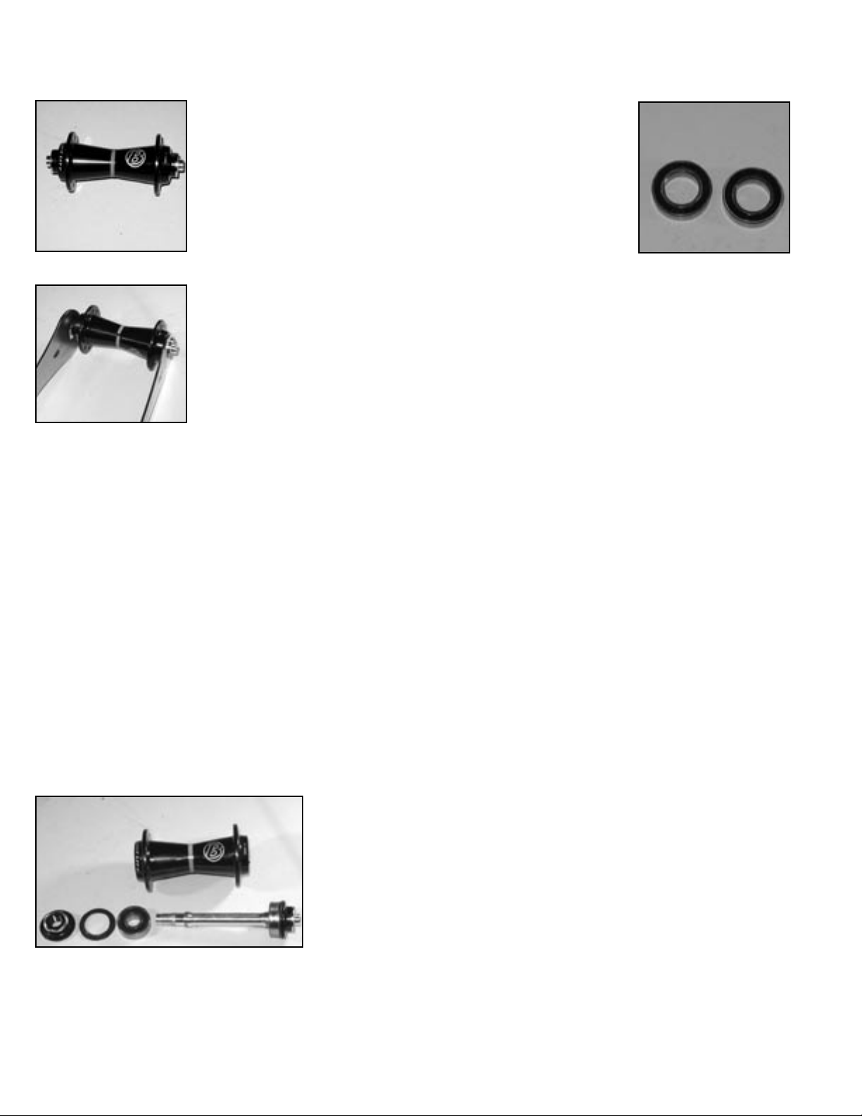
DISASSEMBLY
1. Loosen both end caps by
rotating them in opposite directions with your fingers.
2. Clamp the axle end cap
(either side) in the axle vise
(avoid over tightening).
3. Pull the wheel upward
(Fig. 1J) to remove the end cap
held by the vise.
4. Tap the axle out of the
hub with the hammer (Fig. 2J).
5. Slide the bearing off the
axle (Fig. 3J).
6. Re-insert the axle into
the hub from the side opposite
the remaining bearing. With the
axle end resting on the inside of
the bearing, tap the bearing out
of the shell with the hammer.
Clean and inspect all components. If any cracks or other
damage are visible, replace the
part.
5. Grease both the outer sur-
face of both bearings.
End cap
V-seal
6. Pull the V-seal off the both
end caps (Fig. 13I). Clean each
seal thoroughly with a cloth,
lightly grease it, and reinstall it
on the end cap with the open ‘V’
facing the hub.
7. Push the completed
adapters into place with your
fingers.
After completing assembly of the hub, check its function by spinning the axle with your fingers. It should rotate freely without irregular friction. A small
amount of lateral play is acceptable if the play is eliminated when the wheel is installed with the
quick release properly closed.
Fig. 6J
2002 Race Lite, ATB, Race Lite 29, 2003 Race X Lite ATB
O.L.D. . . . . . . . . . . . . . . . . . . . . . . . . . . . . . . . . . . . . . . . . . . . . . . . 100 mm
Spoke hole quantity . . . . . . . . . . . . . . . . . . . . . . . . . . . . . . . . . . . . . . 24°
Spoke hole P.C.D. . . . . . . . . . . . . . . . . . . . . . . . . . . . . . . . . . . . . 40.5 mm
Q.R. rod outer diameter . . . . . . . . . . . . . . . . . . . . . . . . . . . . . . . . . 5 mm
2002/2003 Race X Lite
O.L.D. . . . . . . . . . . . . . . . . . . . . . . . . . . . . . . . . . . . . . . . . . . . . . . . 100 mm
Spoke hole quantity . . . . . . . . . . . . . . . . . . . . . . . . . . . . . . . . . . . . . . 20°
Spoke hole P.C.D. . . . . . . . . . . . . . . . . . . . . . . . . . . . . . . . . . . . . 38.0 mm
Q.R. rod outer diameter . . . . . . . . . . . . . . . . . . . . . . . . . . . . . . . . . 5 mm
2002/2003 Race X Lite Carbon, Race X Lite Aero
O.L.D. . . . . . . . . . . . . . . . . . . . . . . . . . . . . . . . . . . . . . . . . . . . . . . . 100 mm
Spoke hole quantity . . . . . . . . . . . . . . . . . . . . . . . . . . . . . . . . . . . . . . .16°
Spoke hole P.C.D. . . . . . . . . . . . . . . . . . . . . . . . . . . . . . . . . . . . . 38.0 mm
Q.R. rod outer diameter . . . . . . . . . . . . . . . . . . . . . . . . . . . . . . . . . 5 mm
Fig. 4J
Fig. 5J
ASSEMBLY
1. Clamp the long bearing
press into the vise.
2. Push the new bearing over
the front axle. Insert the axle
into the bearing press (Fig. 4J).
2. Place the wheel over the
axle and pull the axle out by
about 10 mm (1/2 inch). Push
the second bearing over the axle
and into the hub.
3. Center the axle using the
short bearing press.
4. Tap both bearings into
place with the hammer (Fig. 5J)
at the same time.
Turn the axle to check the bearings. You should not be
able to feel any irregular friction. Make sure that there is
no play in the axle.
26
2003 Bontrager Service Manual
Page 26

Exploded view and Parts list
Pos Description
1 End nut
2 V-seal
4
1
2
3
5
3
2
1
3 Bearing
4 Axle
5 Hub shell
Description Model year Model for Parts included (qty) TCG Part #
Axle kit 00/01/02/03 all 1(2), 2(2), 3(2), 4 70357
V-seal 00/01/02/03 all 2 211342
Bearing 00/01/02/03 all 3(6802, 15/24 x 5mm) 211344
End cap kit 00/01/02/03 all 1(2) 221803
2003 Bontrager Service Manual
27
Page 27

Pro rear hub
Bontrager Race Lite ATB, Race Lite 29, Race X Lite, Race X Lite Carbon rear wheels, Race Lite Aero
A running change to hubs was made in 2001; the newer hub has a part number embossed in the shell. See exploded dioagrams for differences
Recommended tools
Long bearing press
Short bearing press
17mm cone wrench
Multi-purpose grease
Bench vise
Axle vise
Hammer, soft faced
Thin-bladed slot screwdriver
Fig. 1I
DISASSEMBLY
Hub parts and names are referenced on next page.
Disassemble the freehub
Spacer
1. Place the axle vise in the
bench vise and clamp the lefthand end of the axle.
Star
ratchet
2. Pull sharply with your
fingers to remove the cassette,
with the freehub body attached
(Fig. 1I).
Fig. 2I
3. Remove the star ratchet,
spacer and spring (under the star
ratchet) from the hub (Fig. 2I).
4. Remove the second star
ratchet and second spring from
the freehub body.
Disassemble the ring nut
1. Clamp the spline tool into
a bench vise (Fig. 3I).
2. Push the right side axle
Fig. 3I
end into the cylinder. With the
splines engaged, turn the wheel
Bearing
firmly in an anti-clockwise direction. The ring nut will be loosened, and the seal between the
hub and freehub body will fall
over the spline tool onto the vise.
3. Thoroughly clean and
inspect all components, including inside the hub, with a dry
Fig. 4I
cloth. If necessary, use a tooth-
brush. If cracks or any other
damage is visible, the parts must
Spacer
be replaced.
Disassemble the bearings
1. From the right side, tap
the axle out of the hub with the
hammer (Fig. 4I). Remove the
axle from the hub.
2. Slide the left end cap, seal
Fig. 5I
and bearing off the axle.
3. Turn the axle around and
insert it into the left side of the hub until the axle collar
butts against the bearing. Tap the second bearing out
with the hammer.
4. Thoroughly clean and inspect all components with
a dry cloth. If cracks or any other damage is visible, the
parts must be replaced.
ASSEMBLY
Install the right hand bearing
1. Clamp the spline tool into
a vise.
2. Place the spacer over the
splines (Fig. 5I).
3. Place the bearing onto the
long end of the axle and push
the bearing onto the spline tool
(Fig. 6I).
4. Place the wheel over the
axle, drive side down. Push the
short bearing press over the
other end of the axle. Tap the
bearing into place with the hammer (Fig. 7I).
Install the ring nut
1. Clamp the spline tool into
the vise with only the splines
above the jaws (Fig. 8I).
2. Inspect the ring nut for
cracks or damage. If damaged,
replace it.
3. Place the ring nut with the
recess uppermost over the splines
(Fig. 9I). Place the spacer ring flat
inside the ring nut.
4. Place the wheel, drive side
down, over the spline tool. Insert
the right axle end through the
spline tool. Carefully screw the
ring nut into the hub by turning
the wheel clockwise.
Install the freehub body seal
Important: When installing a new seal, only the right-hand
bearing should be in place. The left-hand bearing must not
be pressed in until after the seal has been installed.
1. Inspect the seal. If the seal
shows signs of wear or damage,
replace it.
2. Clamp the short bearing
press into a vise (Fig. 10I) and
place the wheel, drive side up,
over the tool.
3. Place the seal over the
freehub body seal installation tool
(Fig. 11I) with the ‘V’ facing the
hub.
4. With the seal on the tool,
push them together over the axle.
5. Place the long bearing
press over the axle.
6. Press the seal into the hub by tapping it with the
hammer.
Install the left hand bearing
1. Clamp the spline tool into the bench vise (Fig. 3I).
Spacer
Fig. 6I
Fig. 7I
Fig. 8I
Ring nut
Fig. 9I
Fig. 10I
28
2003 Bontrager Service Manual
Page 28

Freehub body seal
2. Push the wheel over the
tool, drive side down.
3. Place the bearing care-
fully into the hub (Fig. 12I).
4. Place the short bearing
press over the axle (Fig. 7I). Tap
the bearing into place with the
hammer.
Turn the axle and check that you do not feel any irregular
Fig. 11I
friction.
5. Lightly grease the surface
of the bearing.
6. Pull the V-seal off the
end cap (Fig. 13I). Clean it
thoroughly with a cloth, lightly
grease it, and reinstall it on the
end cap with the open ‘V’ facing
the hub.
7. Replace the completed
end cap onto the left axle end.
Fig. 12I
Install the freehub
End cap
V-seal
1. Grease the splines inside
the hub shell with DT Swiss special grease (only).
2. Push the spacer over
the axle (Fig. 14I) until it butts
against the bearing.
3. Insert the spring, with
the large diameter in contact
Fig. 13I
with the bearing (Fig. 14I).
4. Clean the outside end of the
freehub body with a clean cloth.
Before positioning the spacer and the ratchet in the freehub body, check that the freehub body bearings spin freely without binding. If any binding or scratching is detected, replace the freehub body with
a new or reconditioned one.
5. Carefully clean the star
ratchets with a dry cloth. Inspect
both star ratchets for damage.
Spring
Spacer
If any damage is visible, replace
the ratchet.
5. Lightly grease both star
ratchets with DT Swiss special
grease (only).
6. Place the spacer ring
into the freehub body. Place the
spring into the freehub body
Fig. 14I
with the large diameter end in
contact with the spacer ring
(Fig. 15I).
7. Place both greased star
ratchets into the freehub body
(Fig. 16I).
8. Push the freehub body,
together with the cassette, over
the axle.
Caution: Ensure the freehub body is not tilted !
Fig. 15I
9. Pull the V-seal off the right
end cap (Fig. 13I). Clean it thoroughly with a cloth, lightly grease
it, and reinstall it on the end cap
with the open ‘V’ facing the hub.
10. Place the end cap over
the right end of the axle and
manually press into place.
Ensure the end cap is not tilted
and that it audibly clicks into
place.
After completing assembly of the hub, check its function
by giving the cassette a sharp, quick spin. If the ratchets do not catch, there could be too much grease
inside the freehub body, or the wrong type of grease was used. In this case, remove some of the grease
or replace it using the correct grease.
Fig. 16I
2003 Bontrager Service Manual
Part list on following page
29
Page 29

2003 Bontrager Service Manual
Exploded view and Parts list- 2001-2003
4
1
2
3
13
3
5
6
A running change to hubs was made in 2001; the newer hub (shown here)
has a part number embossed in the shell. See the following page for the
earlier model hub.
8
7
9
10
10
9
11
Pos Description
1 End cap, left
2 V-seal
3 Bearing
4 Axle
5 Spacer
6 Ring nut
7 Washer
8 Spacer
9 Spring
10 Star ratchet
11 Freehub body
12 End cap, right
13 Hub shell
12
Description Model year Model for Parts included (qty) TCG Part #
Freehub kit 02/03 all 8, 9(2), 10(2), 11 70354
(Shimano)
Freehub kit 02/03 all 8, 9(2), 10(2), 11 211579
(Campagnolo)
Star ratchet 02/03 all 9(2), 10(2) 211343
and spring kit
Axle kit 02/03 all road 1, 2, 3(2), 4, 13 70355
130mm O.L.D.
(Shimano)
Axle kit 02/03 all road 1, 2, 3(2), 4, 13 211580
130mm O.L.D.
(Campagnolo)
Axle kit 02/03 Race Lite ATB 1, 2, 3(2), 4, 13 70356
135mm O.L.D.
V-seal 02/03 all 2 211342
Freehub seal 02/03 all 7 211591
Bearing 02/03 all 3 (6902, 15/28 x 7mm) 211345
2001, 2002 Race Lite, 2003 Race X Lite ATB
O.L.D. . . . . . . . . . . . . . . . . . . . . . . . . . . . . . . . . . . . . . . . . . . . . . . . 135 mm
Spoke hole quantity . . . . . . . . . . . . . . . . . . . . . . . . . . . . . . . . . . . . . . 24°
Spoke hole P.C.D., right . . . . . . . . . . . . . . . . . . . . . . . . . . . . . . 53.0 mm
Spoke hole P.C.D., left . . . . . . . . . . . . . . . . . . . . . . . . . . . . . . . 44.0 mm
Q.R. rod outer diameter . . . . . . . . . . . . . . . . . . . . . . . . . . . . . . . . . 5 mm
2002/2003 Race X Lite
O.L.D. . . . . . . . . . . . . . . . . . . . . . . . . . . . . . . . . . . . . . . . . . . . . . . . 130 mm
Spoke hole quantity . . . . . . . . . . . . . . . . . . . . . . . . . . . . . . . . . . . . . . 24°
Spoke hole P.C.D., right . . . . . . . . . . . . . . . . . . . . . . . . . . . . . . 53.0 mm
Spoke hole P.C.D., left . . . . . . . . . . . . . . . . . . . . . . . . . . . . . . . 44.0 mm
Q.R. rod outer diameter . . . . . . . . . . . . . . . . . . . . . . . . . . . . . . . . . 5 mm
2002/2003 Race X Lite Carbon, Race X Lite Aero
O.L.D. . . . . . . . . . . . . . . . . . . . . . . . . . . . . . . . . . . . . . . . . . . . . . . . 130 mm
Spoke hole quantity . . . . . . . . . . . . . . . . . . . . . . . . . . . . . . . . . . . . . . .16°
Spoke hole P.C.D., right . . . . . . . . . . . . . . . . . . . . . . . . . . . . . . 53.0 mm
Spoke hole P.C.D., left . . . . . . . . . . . . . . . . . . . . . . . . . . . . . . . 44.0 mm
Q.R. rod outer diameter . . . . . . . . . . . . . . . . . . . . . . . . . . . . . . . . . 5 mm
30
2003 Bontrager Service Manual
Page 30

Exploded view and Parts list- 2000-2001
Pos Description
4
1
2
3
14
7
6
8
9
10
10
11
12
13
1 End cap
2 V-seal
3 Bearing
4 Axle
6 Freehub seal
7 Bearing
8 Spacer
9 Spring
10 Star ratchet
11 Washer
12 Freehub body
13 End nut, right
14 Hub shell
Description Model year Model for Parts included (qty) TCG Part #
Freehub kit 2000 Race, Race Lite 8, 9(2), 10(2), 12 70354
(Shimano)
Star ratchet 2000 Race, Race Lite 9(2), 10(2) 211343
and spring kit
Axle 2000 Race, Race Lite 1, 2, 3(2), 13 (135mm O.L.D.) 70356
Freehub seal 2000 Race, Race Lite 6 211591
Bearing, left 2000 Race, Race Lite 3 (6902, 15/28 x 7mm) 211345
Bearing, right 2000 Race, Race Lite 7 (3802, 15/24 x 7mm) 211346
2000 Race Lite
O.L.D. . . . . . . . . . . . . . . . . . . . . . . . . . . . . . . . . . . . . . . . . . . . . . . . 135 mm
Spoke hole quantity . . . . . . . . . . . . . . . . . . . . . . . . . . . . . . . . . . . . . . 28°
Spoke hole P.C.D., right . . . . . . . . . . . . . . . . . . . . . . . . . . . . . . 53.0 mm
Spoke hole P.C.D., left . . . . . . . . . . . . . . . . . . . . . . . . . . . . . . . 44.0 mm
Q.R. rod outer diameter . . . . . . . . . . . . . . . . . . . . . . . . . . . . . . . . . 5 mm
2003 Bontrager Service Manual
31
 Loading...