

Page 1
Installation and
Operations Manual
H-IM-81E September 2010 Part No. 25001801
PRO3 Top Mount
Packaged Refrigeration System
For Indoor Applications
Table of Contents
1. Owner’s Installation Instructions
Performance/Electrical Data
Specications .................................................................................... 2
Dimensional Diagrams ..................................................................3
Space and Location Requirements
Recommended Unit Placement .................................................4
Rigging
Mounting............................................................................................5
Inspection
General Safety Information
Standard Installation Procedure ................................................6
2. Controllers
Controllers and Program Settings ...................................... 7-17
3. Service Information
System Troubleshooting Chart ................................................ 18
Replacement Parts ....................................................................... 19
4. Wiring Information
Electrical Wiring Diagrams ..................................................20-25
5. Warranty Information ........................................................ 26
© 2010 Heatcraft Refrigeration Products, LLC
Page 2
PERFORMANCE / ELECTRICAL DATA
Installation and Operations Manual
1. Owner’s Operating Instructions
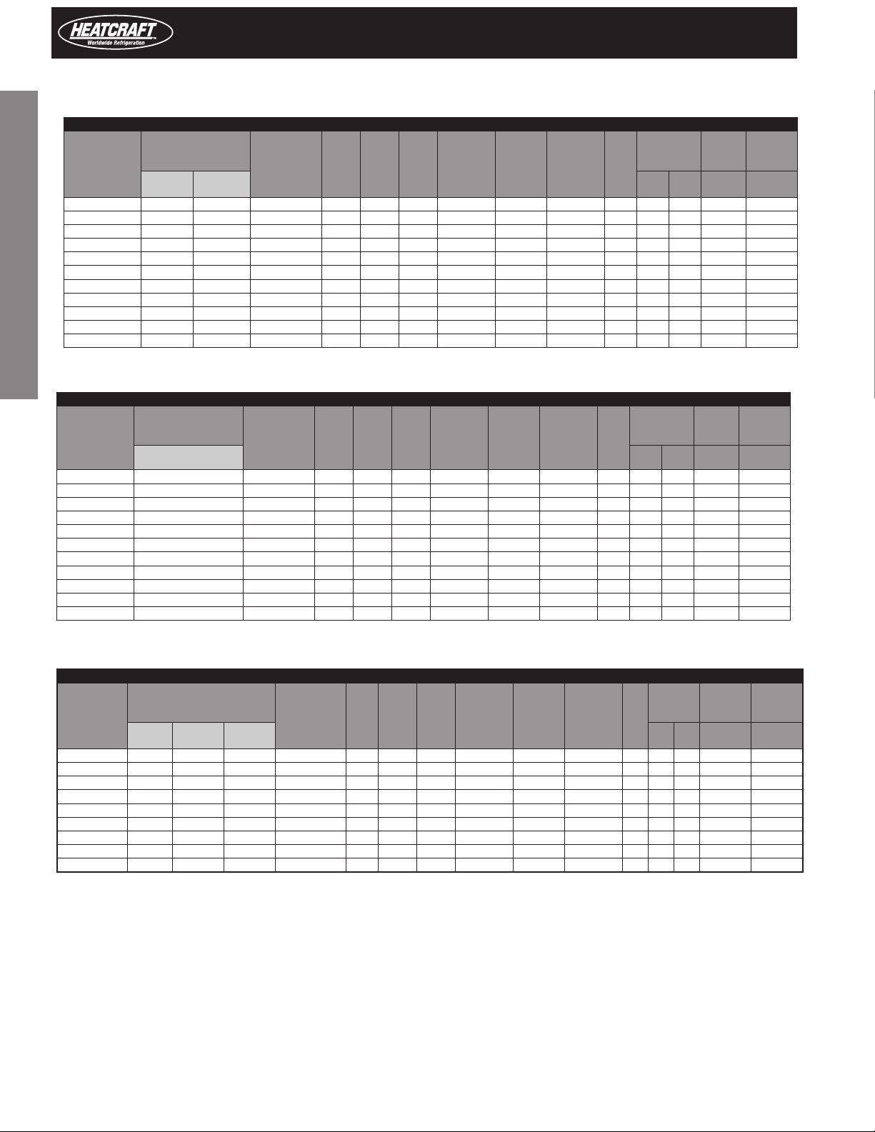
TABLE 1 Cooler Air Defrost Systems
Model
PTN026H6A^ 2,610 2,740 115/1/60 7.4 15 5.9 340 Yes 5-20R A 88 40 12 3,000
PTN031H6A^ 3,160 3,310 115/1/60 8.3 15 6.9 340 Yes 5-20R A 90 41 16 3,800
PTN042H6A^ 4,360 4,570 115/1/60 11.3 15 9.3 340 Yes 5-20R A 92 42 14 5,500
PTN050H6A^ 5,120 5,370 115/1/60 14.0 20 11.6 350 Yes 5-20R B 192 87 27 6,700
PTN050H6B^ 5,120 5,370 208-230/1/60 7.0 15 5.9 350 Yes 6-15R B 192 87 27 6,700
PTN067H6B^ 6,860 7,190 208-230/1/60 11.5 15 9.5 550 Yes 6-15R B 207 94 29 8,700
PTN076H6B^ 7,500 7,840 208-230/1/60 9.3 15 7.8 500 Yes 6-15R B 211 95 32 9,700
PTN104H6B^ 11,190 11,810 208-230/1/60 14.8 20 12.4 875 Yes 6-20R C 270 122 47 16,800
PTN104H6C^ 11,190 11,810 208-230/3/60 11.0 15 9.3 875 No – C 265 120 47 16,800
PTN133H6B^ 12,790 13,500 208-230/1/60 14.8 20 12.4 825 Yes 6-20R C 290 132 52 18,000
PTN133H6C^ 12,790 13,500 208-230/3/60 11.0 15 9.3 825 No – C 285 129 52 18,000
Model
PTN024M6A^ 2,610 115/1/60 7.4 15 5.9 340 Yes 5-20R A 88 40 12 3,000
PTN029M6A^ 3,160 115/1/60 8.3 15 6.9 340 Yes 5-20R A 90 41 16 3,800
PTN040M6A^ 4,360 115/1/60 11.3 15 9.3 340 Yes 5-20R A 92 42 14 5,500
PTN047M6A^ 5,120 115/1/60 14.0 20 11.6 350 Yes 5-20R B 192 87 27 6,700
PTN047M6B^ 5,120 208-230/1/60 7.0 15 5.9 350 Yes 6-15R B 192 87 27 6,700
PTN063M6B^ 6,860 208-230/1/60 11.5 15 9.5 550 Yes 6-15R B 207 94 29 8,700
PTN072M6B^ 7,500 208-230/1/60 9.3 15 7.8 500 Yes 6-15R B 211 95 32 9,700
PTN099M6B^ 11,190 208-230/1/60 14.8 20 12.4 875 Yes 6-20R C 270 122 47 16,800
PTN099M6C^ 11,190 208-230/3/60 11.0 15 9.3 875 No – C 265 120 47 16,800
PTN128M6B^ 12,790 208-230/1/60 14.8 20 12.4 825 Yes 6-20R C 290 132 52 18,000
PTN128M6C^ 12,790 208-230/3/60 11.0 15 9.3 825 No – C 285 129 52 18,000
BTUH @95°F
35° F Box
Temp
34° F Box Temp lbs. kg oz. BTUH
38° F Box
Temp
BTUH @95°F
Voltage MCA MOPD
TABLE 2 Cooler Electric Defrost Systems
Voltage MCA MOPD
Unit
Amps
Unit
Amps
Evaporator
CFM
Evaporator
CFM
Supplied
Plug
Supplied
Plug
Matching
NEMA
Receptacle
Matching
NEMA
Receptacle
Approx. Net
Weight
Fig.
lbs. kg oz. BTUH
Approx. Net
Weight
Fig.
Refrig.
Charge
R-404A
Refrig.
Charge
R-404A
Total
Heat of
Rejection
Total
Heat of
Rejection
TABLE 3 Freezer Electric Defrost Systems
Model
PTN019L6A^ 2,470 N/A N/A 115/1/60 13.0 20 13.0 340 Yes 5-20R A 101 46 14 4,000
PTN021L6A^ 2,680 2,160 1,340 115/1/60 14.5 20 12.3 350 Yes 5-20R B 213 97 26 4,300
PTN031L6B^ 2,680 2,160 1,340 208-230/1/60 7.6 15 6.5 350 Yes 6-15R B 213 97 26 4,300
PTN031L6B^ 4,220 3,190 2,060 208-230/1/60 13.8 15 11.6 550 Yes 6-15R B 221 100 28 6,300
PTN044L6B^ 5,870 4,530 3,400 208-230/1/60 15.9 20 13.3 520 Yes 6-15R B 225 102 29 9,900
PTN052L6B^ 7,000 5,360 3,910 208-230/1/60 18.1 20 15.3 900 No – C 275 125 45 10,900
PTN052L6C^ 7,000 5,360 3,910 208-230/3/60 12.2 15 13.0 900 No – C 270 122 45 10,900
PTN069L6B^ 9,060 7,100 5,250 208-230/1/60 23.8 30 20.0 875 No – C 280 127 47 15,300
PTN069L6C^ 9,060 7,100 5,250 208-230/3/60 15.9 20 14.2 875 No – C 275 125 47 15,300
0° F Box
Temp
95°F Ambient
-10° F
Box Temp
-20° F
Voltage MCA MOPD
Box Temp
Unit
Amps
Evaporator
CFM
Plug
Supplied
Matching
NEMA
Receptacle
Approx.
Net
Weight
Fig.
lbs. kg oz. BTUH
Refrig.
Charge
R-404A
Total
Heat of
Rejection
^This space may be blank or completed with an H designation indicating PSC motors, or an E for EC Motors on Evaporators
2
Page 3
PRO3 Top Mount Packaged Refrigeration System | Indoor
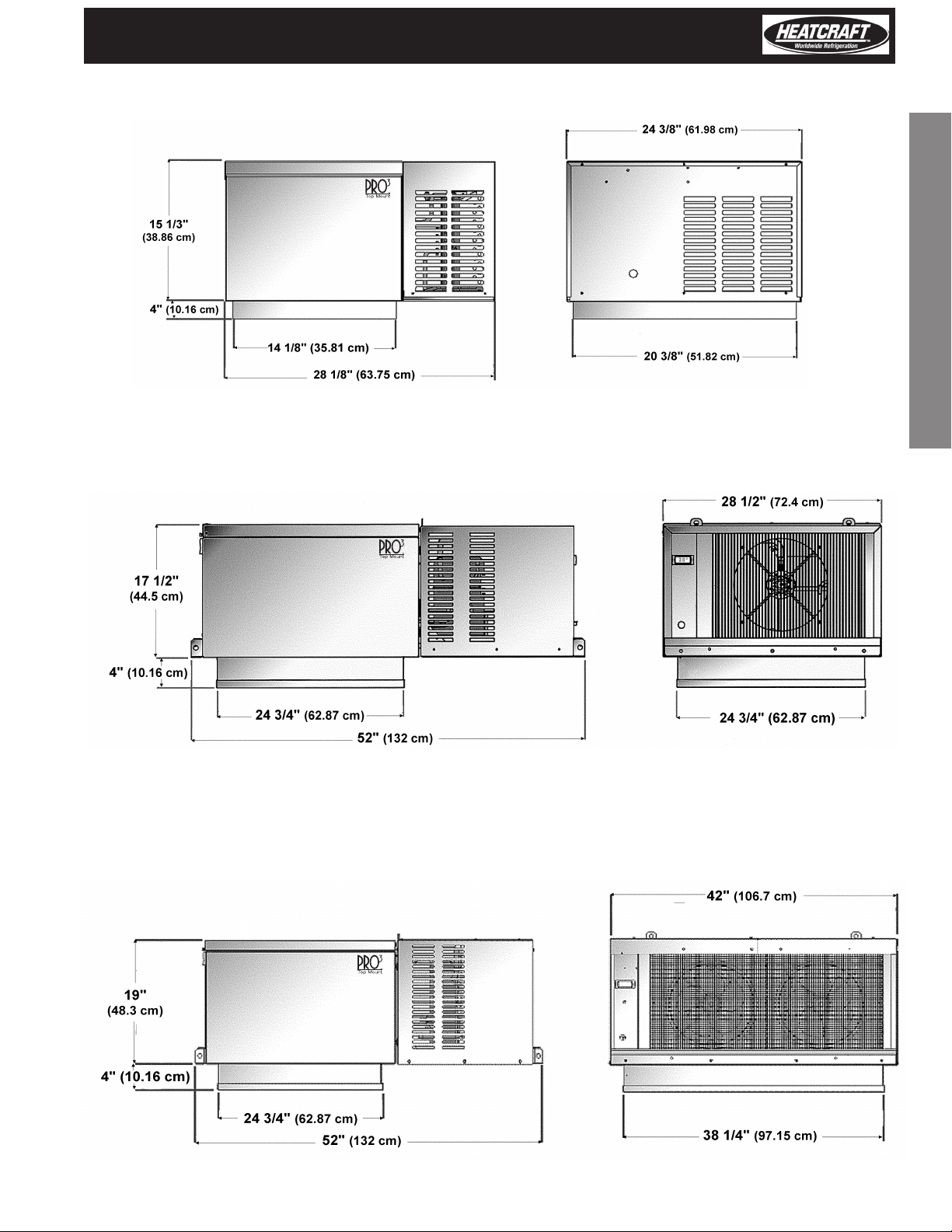
DIMENSIONAL DIAGRAMS
Figure A. Small Cabinet Dimensions (See Reference on page 2)
14 1/2" x 20 3/4" panel opening required for evaporator section of small cabinet sizes.
Figure B. Medium Cabinet Dimensions (See Reference on Page 2).
25" x 25" panel opening required for evaporator section of medium cabinet sizes.
1. Owner’s Operating Instructions
Figure C. Large Cabinet Dimensions (See reference on Page 2).
25" x 38 1/2" panel opening required for evaporator section of large cabinet sizes.
3
Page 4
Installation and Operations Manual
Space and Location Requirements
For PTN models.
1. Owner’s Operating Instructions
The most important consideration which must be taken into account
when deciding upon the location of air-cooled equipment is the provision
for a supply of ambient air to the condensing unit. Ignoring this essential
requirement will result in higher condensing pressure and contribute
to poor operation or potential equipment failure. Units must not be
located in the vicinity of steam, hot air or fume exhausts. Adequate
air circulation through the condensing unit is critical to ensure proper
equipment operation. Improper installation can damage the unit and will
void the warranty. penthouse-style packaged units are designed
for indoor use only in ambient temperatures of 50°F to 100°F. The unit
cabinet is not approved for weather tight applications.
Another important consideration is that the unit should be mounted
away from noise sensitive spaces and must have adequate support to
avoid vibration and noise transmission into the building. Storage should
not be allowed on top of walk-in structure. Unit must not be enclosed
in an unventilated space.
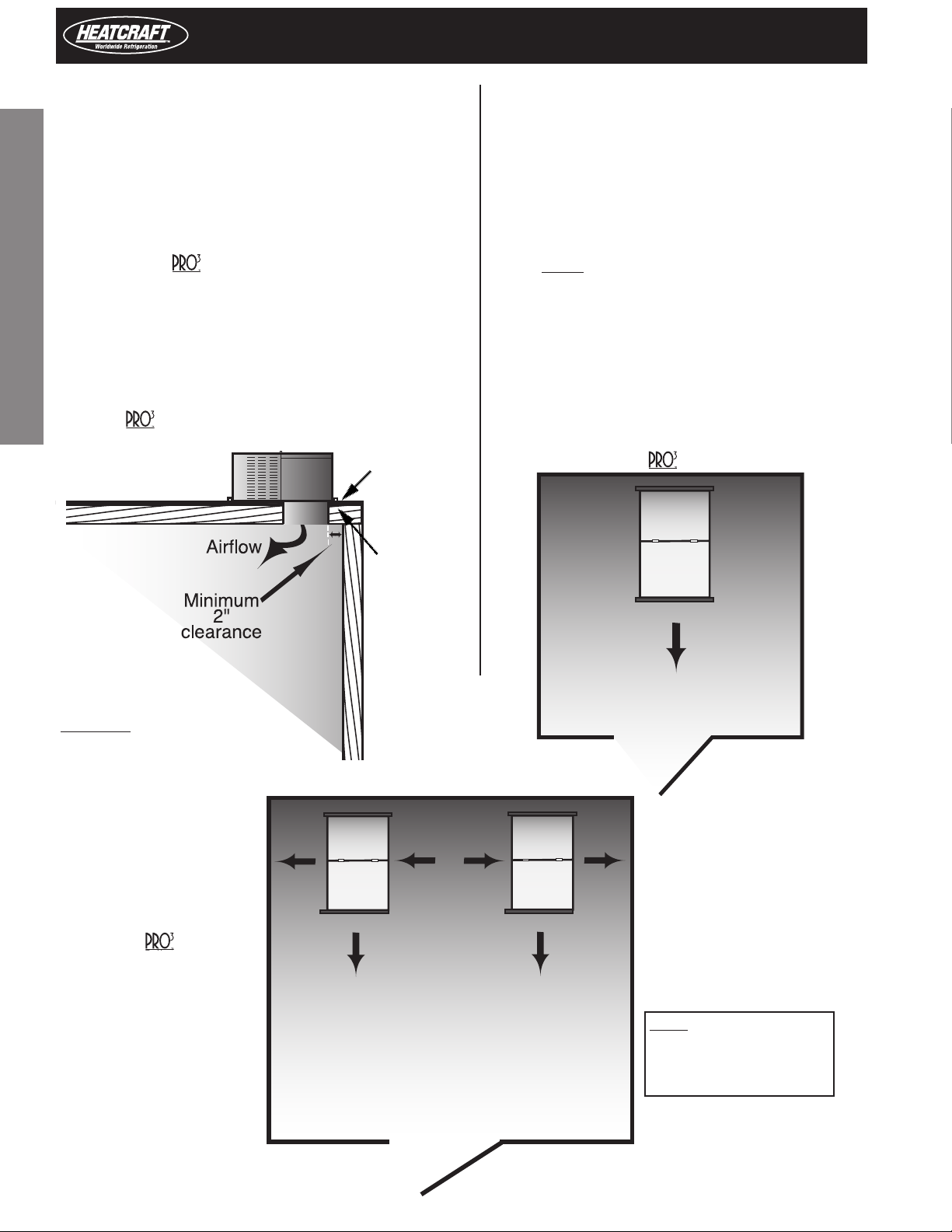
Figure 1.
PTN models
Minimum 2" clearance from
opening to adjacent wall. No
storage is allowable on top of
walk-in structure.
IMPORTANT: Ventilation air
must be provided for the
condensing unit.
Structure must not be masked
to building ceiling, blocking air
ow to unit.
System Space and Location Requirements for
Side View
Allow 2 feet
clearance above
unit to remove
top panel and
to allow service
access.
Mounting rails
may be used to
attach unit to
ceiling.Throughbolts should
be insulated or
non-conductive
to prevent
sweating.
Recommended Unit Placement
Some general rules for the evaporator section placement which
must be followed are:
1. Ensure that the structural integrity of the box can
withstand the weight of the top mounted equipment.
2. The air pattern must cover the entire room.
3. NEVER locate the evaporator section over doors.
4. Location of aisles, racks, etc. must be known.
5. Never remove or unlock any panel cam-locks to
install top mounted equipment.
The size and shape of the storage will generally determine the type
and number of units to be used and their location.
Top View
One
Evaporator
Airow
System
Evaporator
Section
Compressor
Section
W
Min.
Evaporator
Section
Compressor
Section
2 x Width
Min.
Evaporator
Section
Compressor
Section
W
Min.
Multiple units must be spaced
properly to provide adequate air
circulation.
Top View
Two Systems
Evaporator
Airow
Evaporator
Airow
PTN Models
NOTE: Always avoid
W = Unit Width
placement of units
directly above doors
and door openings.
4
Page 5
PRO3 Top Mount Packaged Refrigeration System | Indoor
Rigging
Rigging holes are provided on all medium and large cabinet
models. Caution should be exercised when moving these
units. To prevent damage to the unit housing during rigging,
cables or chains used must be held apart by spacer bars. The
mounting platform or base should be level and located so as
to permit free access of supply air.
Access Requirements
Provide adequate space at the compressor end of the unit for
servicing. Provide two (2) feet of space above unit for service.
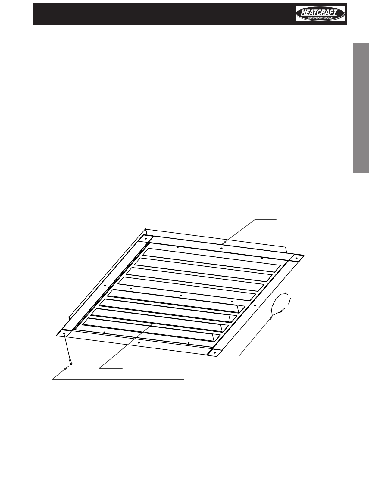
Trim Ring Installation Detail
Mounting
The system requires an opening in the ceiling to the dimensions stated on page 3. Mounting rails are located at both
ends of the chassis. Mounting rails may be used to attach
unit to ceiling. Through-bolts should be insulated or nonconductive to prevent sweating. The chassis is weather
stripped around the air grille and will seal to the box roof.
The trim ring (shipped loose), when provided, should be
installed around the air diuser when secured with the
hardware provided. Be sure to adhere to your local standard
construction codes.
1. Owner’s Operating Instructions
Evaporator Grill
Trim Pieces (4)
Overlap as Shown
Ceiling of Walk-in.
Self Drilling Screw
5
Page 6
Inspection
Installation and Operations Manual
1. Owner’s Operating Instructions
1. Each shipment should be carefully checked against the bill
of lading.
2. The shipping receipt should not be signed until all items listed
on the bill of lading have been accounted for.
3. Check packaging for signs of damage.
4. Any shortage or damages should be immediately reported to
the delivering carrier.
5. Damaged material becomes the delivering carrier’s
responsibility, and should not be returned to the manufacturer
unless prior approval is given to do so.
6. When unpacking the system, care should be taken to
prevent damage.
7. Avoid removing the shipping base until the unit has been
moved to the nal destination.
8. Complete warranty return card for each unit and mail to
Heatcraft Refrigeration Products.
General Safety Information
1. Installation and maintenance to be performed only by a
licensed contractor.
2. Ensure that the structural integrity of the box can withstand
the weight of the (See page 2, Table 3 for unit weights).
3. Avoid contact with sharp edges and coil surfaces. They are a
potential injury hazard. Wear gloves during moving and rigging.
4. Make sure all power sources are disconnected before any
service work is done on units.
Standard Installation Procedure
PTN Models
For Indoor Use Only
1. Inspect packaging for shipping damage.
Open package and inspect unit for concealed damage.
2. Review the space and location requirements on page 4.
3. Provide a nished opening in the box ceiling, to the
appropriate dimensions and structural strength as stated on
page 2, Table 3.
4. DO NOT remove or disengage any box cam-locks in order
to install the
TABLE 4 Control Factory Default Settings
PTT
Models
H - Cooler Models
Air Defrost
M - Cooler Models
Electric Defrost
L - Freezer Models
Electric Defrost
unit.
Temperature
Set Points
Defrost
Start Times
38˚F 4 / day 60 min. – – 38˚F 3
34˚F 4 / day 40 min. 2 min. 2 min. 65˚F 2
-10˚F 4 / day 40 min. 2 min. 2 min. 65˚F 1
5. Clean the roof of the box to provide a good sealing
surface for the unit weatherstrip. Refer to box
manufacturer’s instructions for any procedures or processes
necessary to ensure the integrity of the exposed foam in the
panels is not compromised.
6. Check the mounting surface with a level.
a surface that is within 1° of level or better and no more
than a 5/8" drop per 3 feet (17mm drop per meter).
7. For walk-in boxes with aluminum top panels, it is
recommended that a thermal break be placed on the roof
adjacent to the opening to prevent the possibility of sweating.
8. Place the unit gently into the provided opening with the
evaporator air ow directed toward the door (See page 4).
Be careful not to damage the grill during installation.
9. Ensure that the condenser air ow is not obstructed.
10. Install the trim around the inside opening with the
hardware provided.
11. Connect unit to power supply using the cord with plug, if
provided, or hard wire. Adhere to local electrical/wiring codes.
IMPORTANT:
• Do not use extension cords to connect unit to power.
Plug-in to grounded three prong outlet.
•
• Do not remove grounding prong.
• Do not use a power adapter.
12. Apply power to unit. All controls are preset to factory
default settings (See Table 4).
13. Check unit for proper operation.
14. To change defaults as a group follow these steps:
1. Press Set button and hold in until the display ashes "PS".
2. Press the Set Button and the display will change to "0" and will
begin to ash.
3. Press the up button until "22" is displayed.
4. Press the Set button.
5. Press the down button 2 times. "EZY" will be displayed.
6. Press the Set button.
7. Select the proper number for the model needed by pressing
the up or down key.
• 1 - L Low temperature model
• 2 - M Med temperature model
• 3 - H High temperature model
8. Press Set and wait for unit to return out of programming mode.
9. Disconnect Power
10. Press the Set Button while turning unit On
11. "CE" should display to verify programming display
Defrost Duration
(Maximum)
Drip
Time
Fan
Delay
Defrost Termination
Set Point
units require
EZY
Default
6
Page 7
PRO3 Top Mount Packaged Refrigeration System | Indoor
Refrigeration/Defrost Sequence of Operation
The sequence of operation varies depending on the model that has been installed. The three basic models are Low Temperature, Medium
Temperature, and High Temperature models. The particular model can be determined by the seventh digit of the model number. See Tables
1-3 for details and settings.
Control of the refrigeration and defrost system is provided by the Carel controller along with a space (box) temperature sensor and a coil
(defrost) temperature sensor. The controller will control on and o switching for the compressor, condenser fan motor(s) (cycles with the
compressor), evaporator fan motor(s) and electric defrost heaters for electric defrost.
The Carel controller is pre-programmed for all three applications. This is done with the use of the parameter list. The parameter list can be
changed by entering the Carel Controller and changing the “EZY” setting. See page 13.
TABLE 5 Model PTN | Low Temperature Models | EZY SETTING =1
SET POINT IS 10° F
These models are intended for freezer applications and require electric defrost.
2. Controllers
Status Compressor
Display alternates “OFF” and Room
O
Temperature
On Automatic Defrost on start up O O O On
Defrost Sensor reaches 65° F and
On
defrost is terminated
On Cooling cycle initiated - Drip Time O O O O
Drip Time of 2 minutes ends - coil
On
freeze begins
Evaporator fans start after 2 min
On
delay
Box Temperature (-10.1° F) is
On
satised
On Box Temperature rises to -8.0° F On On On O
Defrost Initiated (Manually or 6
On
hour counter)
On Cooling cycle initiated - Drip Time O O O O
Drip Time of 2 minutes ends - coil
On
freeze begins
Evaporator fans start after 2 min
On
delay
O O O O
O O O O
On On O O
On On On O
O O On O
O O O On Electric Defrost
On On O O
On On On O
Condenser
Fans
Evaporator
Fans
Defrost
Heaters
Notes
If unit shows “OFF”, depress
the “^” button and hold for
three seconds.
If coil temperature is below
65° F. If it is above, defrost is
not initiated. Drip Time and
Freeze Time are ignored.
System Timer Begins/ 2 min
drip time
Compressor starts and
evaporator fans delay for 2
minutes to freeze the coil.
2° F Dierential, Minimum
Compressor O time is 4
minutes
System Timer Begins/ 2 min
drip time
Compressor starts and
evaporator fans delay for 2
minutes to freeze the coil.
7
Page 8
Installation and Operations Manual
TABLE 6 Model PTN | Medium Temperature Models | EZY SETTING =2
SET POINT IS 34° F
These models are intended for cooler applications and have electric defrost. These models are intended for coolers that may be operated at a
lower saturated suction temperature and require electric defrost to clear the coil.
2. Controllers
Status Compressor
Display alternates “OFF” and Room
O
Temperature
On Automatic Defrost on start up O O O On
Defrost Sensor reaches 65° F and
On
defrost is terminated
On Cooling Cycle initiated - Drip Time O O O O
On Drip Time of 2 minutes ends On On On O
On Box Temperature (33.9 F) is satised O O On O
On Box temperature rises to 36° F On On On O
Defrost Initiated (manually or 6
On
hour counter)
Defrost terminated by temperature
On
65° F
On Drip Time of 2 minutes ends On On On O
O O O O
O O O O
O O O On Electric Defrost
On On On O
Condenser
Fans
Evaporator
Fans
Defrost
Heaters
Notes
If unit shows “OFF”, depress
the “^” button and hold for
three seconds.
If coil temperature is below
65° F. If it is above, defrost is
not initiated. Drip Time and
Freeze Time are ignored.
System Timer Begins/2 min
drip time
Compressor and evaporator
fans start
2° F Dierential, Minimum
Compressor O Time is 4
minutes
Compressor starts and
evaporator fans delay for 2
minutes to freeze coil
TABLE 7 Model PTN | High Temperature Models | EZY SETTING =3
SET POINT IS 38° F
These models are intended for cooler applications and have air (O-cycle) defrost. The controller is pre-programmed for 4 defrost per day.
These periods are reprogrammable.
Status Compressor
Display alternates “OFF” and Room
O
Temperature
On Cooling Cycle initiated On On On O System Timer Begins
Box Temperature (37.9° F) is
On
satised
On Box temperature rises to 40.0° F On On On O
Defrost Initiated (Manually or 6
On
hour counter)
Defrost Terminated by time of 40
On
minutes
O O O O
O O On O
O O On On Air Defrost
On On On O
Condenser
Fans
Evaporator
Fans
Defrost
Cycle
Notes
If unit shows “OFF”, depress
the “^” button and hold for
three seconds.
2° F Dierential, Minimum
Compressor O Time is 4
minutes
8
Page 9
PRO3 Top Mount Packaged Refrigeration System | Indoor
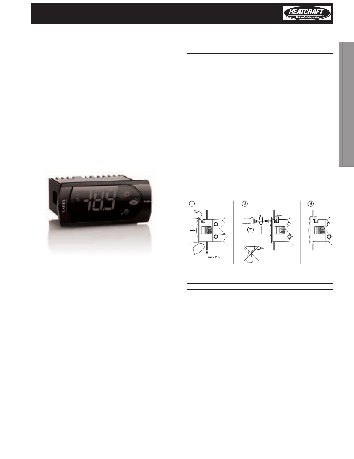
Programming the PJEZC Carel
Electronic Controller
Reprinted with permission from Carel.
The Carel PJEZC control is a fully congurable electronic refrigeration
controller. The Top Mount packaged refrigeration system uses the
Carel controller on all three temperature designated models. The
models dier by a pre-programmed parameter list that is specic
for each application.
There are two levels of programming with the C controller. The rst
level can be accessed through the keypad. Set Point (st), Interval
between defrost (do), Maximum Defrost Duration (dP), and Dripping
Time (dd) are examples of rst level parameters. Second level
parameters can be accessed by entering a password. See “Modifying
Parameters” (page 15).
Installation and Removal
PANEL INSTALLATION FROM THE FRONT USING SCREWS
• The thickness of the fastening panel must not exceed 3 mm;
• Remove the front frame and make sure that the two catches
are in place (these must not protrude from the outline of the
drilling template). If necessary, unscrew the two screws. Do not
unscrew excessively, the screws must not be detached from the
front panel (phase 1);
• Insert the instrument in the opening in the panel and hold it in
position by the centre of the front panel (phase 1);
• Using the screwdriver, tighten the bottom screw 90°, the catch
must come out of its slot and click onto the panel, then tighten
until the front panel is secure; Do not over-tighten, when the
front panel is secured blocks simply make another ½ turn to
compress the gasket; If the catch does not click onto the panel,
unscrew the screw, applying pressure at the same time with
the screwdriver so that the catch moves back. Do not unscrew
too much, the head of the screw must not be raised from the
surface of the front panel (phase 2);
• Repeat the same operation for the top screw (phase 2);
• Apply the front frame (phase 3).
2. Controllers
* Do not over-tighten the screws.
DISMANTLING USING THE SCREWS FROM THE FRONT
• Unclip the front frame;
• Unscrew the bottom screw, at the moment the front panel
detaches from the panel keep pressure on the screw and
unscrew a further 90° to make the catch go back into its slot;
• Repeat for the top screw;
• Remove the instrument from panel, keeping it horizontal
9
Page 10

Installation and Operations Manual
Electrical Connections
WARNINGS:
The electrical connections must only be completed by a
qualied electrician;
A power supply other than the type specied may
seriously damage the system;
Separate as much as possible the probes and digital input
signal cables from the cables carrying inductive loads
and power cables to avoid possible electromagnetic
disturbance. Never lay power cables (including the
electrical cables) and probe signal cables in the same
conduits. Do not install the probe cables in the immediate
vicinity of power devices (contactors, circuit breakers or
2. Controllers
similar);
Reduce the path of the probe and sensor cables as much
as possible, and avoid spiral paths that enclose power
devices. The probes must be connected using shielded
cables (minimum cross-section of each wire: 0.5 mm2);
Avoid direct contact with internal electronic components;
Connection errors (and connections other than those
indicated in this manual) may involve danger to the safety
of the users and cause faults on the instruments and the
components connected;
Fit the unit with all the electromechanical safety devices
required to guarantee correct operation and the complete
safety of the user.
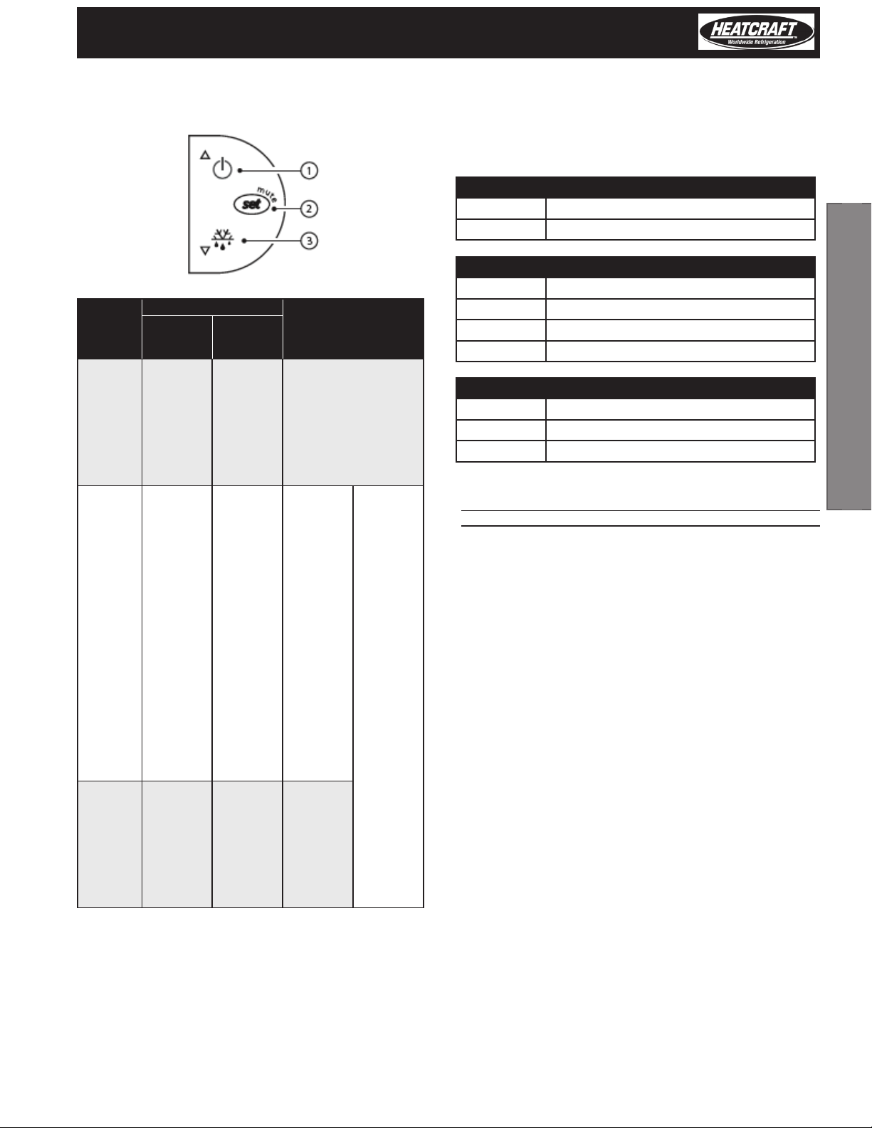
CONTROLLER WIRING
Display
NORMAL OPERATION
BUT. NO. FUNCTION
1 compressor on o call on
2 fan on o call on
3 defrost on o call on
auxiliary
4
5 clock (RTC)
6 alarm
7 digits
output
(AUX)
ON OFF ash
output
active
RTC
available,
enabled
(tEN=1)
and at
least
one time
band has
been set)
alarm in
progress
three digits with decimal point and range
-199 to 999. See parameters /4, /5, /6 for
the type of probe displayed, values in
output
not
active
RTC not
available
or not
enabled
(tEN=0)
or no
time
band set
no
alarm in
progress
°C/°F and decimal point
– on
– on
START
UP
on (if the
clock is
tted)
10
Page 11
PRO3 Top Mount Packaged Refrigeration System | Indoor
Keypads Preliminary Congurations
Once the electrical connections have been completed, simply
power-up the controller to make it operative.
Heatcraft recommends that you check the parameters listed.
Control Parameters
st set point
rd set point dierential
Defrost Parameters
d0 type of defrost
BUT. NO.
1
2
3
NORMAL OPERATION
pressing
the button
alone
more than
3 s: switch
ON/OFF
- 1 s:
displays/
sets the set
point
- more
than 3 s:
accesses
the
parameter
setting
menu
(enter
password
22)
- mutes the
audible
alarm
(buzzer)
more
than 3 s:
activates/
deactivates
the defrost
pressing
with other
buttons
pressed
together
with 3
activates/
deactivates
the
continuous
cycle
–
pressed
together
with 1
activates/
deactivates
the
continuous
cycle
START UP
for 1 s
RESET
current EZY
set
for 1 s
displays
rmware
version
–
pressed
together
(2 and 3)
activate
parameter
reset
procedure
dl interval between two defrosts
dt end defrost temperature
dP maximum defrost duration
Alarm Parameters
Ad temperature alarm delay
AL low temperature alarm threshold/deviation
AH high temperature alarm threshold/deviation
Functions Available from Keypad
ON AND OFF
Switching the instrument ON: press UP for more than 3 s (when
pressing the button, the display shows ON).
Switching the instrument OFF: press UP for more than 3 s. The
display shows the message “OFF”, alternating with the temperature
measured by the set probe.
In o status, the following functions are disabled (if featured by the
model):
• compressor control / duty setting / continuous cycle;
• defrost;
• fan control;
• alarms : ‘LO’, ‘HI’, ‘IA’, ‘cht’, ‘CHT’;
• door switch (A4= 7/8 );
• buzzer (when available)
While the following are enabled:
• temperature display, alternating with the message “OFF”;
• parameter display and setting;
• alarms: “E0”, “E1”, “E2”;
• the internal timer relating to parameter ‘dI’ is updated. If ‘dI’
expires in OFF status, a defrost is performed when restarting;
• auxiliary relay management, only in the following
congurations:
• H1= = 1/2 (“E0” alarm only)
• H1= 3, A4= 6;
2. Controllers
11
Page 12

Installation and Operations Manual
WARNING: When rst connected, easy is already on and
ready to be used. The instrument can be switched on from
a supervisor PC and via an external contact (setting A4=
5). The latter has priority over the other modes.
SET POINT SETTING DESIRED TEMPERATURE VALUE
The easy and easy compact devices control the desired temperature
(set point) inside the cabinet or cold room directly and dynamically.
To view and modify the set point:
• press SET for 1 s, the set value will start ashing;
• increase or decrease the value using UP or DOWN;
• press SET to conrm the new value.
2. Controllers
MANUAL DEFROST
Press DOWN for more than 3 s (activated only if the temperature
conditions are right).
CONTINUOUS CYCLE
Press UP+DOWN for more than 3 s (activated only if the temperature
conditions are right).
The continuous cycle is used to maintain refrigeration active in the
cabinet or cold room, regardless of the temperature inside the unit.
This may be useful for rapidly bringing the temperature below the
set point value.
RAPID DISPLAY OF THE TEMPERATURE READ BY THE OTHER
PROBES
Press the DOWN button to scroll the temperatures read by the
probes. Each time the DOWN button is pressed, the display will
show the name of the probe Pr1, Pr2 or Pr3 (only on the models with
3 inputs and with multifunction input congured as a probe) and
after 1 s the temperature measured by the selected probe will be
displayed.
To display the other probes, press DOWN again.
To return to the normal display, wait 3 s without pressing any buttons
(exit by timeout).
Temperature Display
The temperature displayed, the unit of measure and the decimal
resolution can be set according to the following parameters: /4, /5
and /6.
/4 : select probe displayed
Used to choose whether to display the temperature read by the
control probe (Probe 1), Probe 2 or the status of the multifunction
input (analogue or digital).
Parameter /4 selects the probe shown on the display, all the other
display and control modes remain unchanged.
IMPORTANT: the easy compact models can display up to 2 probes.
/5: select °C/°F
Denes the unit of measure used for temperature control.
/5=0 to work in °C
/5=1 to work in °F.
WARNING:
When changing from one unit of measure to the other, all
the values of the temperature parameters are modied to
the new unit of measure.
The max and min limits of the absolute temperature
parameters are the same for both °C that °F. The range of
temperatures allowed is therefore dierent between °C
and °F:
/6: disable decimal point
Used to enable or disable the temperature display with the resolution
to the tenths of a degree between -20 and + 20 (easy) or -10 and +10
(easy compact).
/6= 0 temperature displayed to the tenth of a degree;
/6=1 temperature displayed without the tenths of a degree.
NOTE: the decimal point is only disabled in relation to the reading
shown on the display (the calculations performed by the controller
remain unchanged).
Temperature Control
The following parameters are used to control the temperature: St,
r1, r2, r3, r4 and rd.
St: set point, r1 minimum value and r2 maximum value of the
set point
Parameter St determines the desired temperature to be maintained
inside the cabinet or cold room (set point). Parameters r1 (minimum
value) and r2 (maximum) set the range of temperatures for setting
the set point.
NOTE: the set point can be set by pressing the SET button (see par.
“Setting the set point (desired temperature value)”).
r3: select direct/reverse operation
Denes the operating mode of the device:
• r3=0: direct with defrost. Used to request the activation of the
compressor when the temperature measured by probe 1 rises
above the set point. This mode also includes defrost
• r3=1: direct without defrost
• r3=2: reverse without defrost. Used to request the activation of
the compressor when the temperature measured by probe 1
falls below the set point. This mode does NOT include defrost.
12
Page 13

PRO3 Top Mount Packaged Refrigeration System | Indoor
Rapid Parameter Set Selection (EZY)
The easy controller features the EZY parameter which is used to
quickly choose a list of parameters, with corresponding values, for
the control of the refrigeration system.
Table of Alarms and Signals
When an alarm is activated, the display shows the corresponding
message that ashes alternating with the temperature; if tted and
enabled, the buzzer and the alarm relay are also activated.
All the alarms have automatic reset (that is, they stop when
the causes are no longer present), except for alarm ‘CHt’ which
has manual reset (instrument on/o using the UP button or by
disconnecting the power supply).
Alarm
E0 active ON probe 1 error= control automatic –
E1 not active ON probe 2 error= defrost automatic d0= 0 / 1 / 4, F0= 1
E2 not active ON probe 3 error= condenser/ product automatic [A4=10]
IA active ON external alarm automatic [A4 = 1] [+A7]
dOr active ON open door alarm automatic [A4 = 7/8][+A7]
LO active ON low temperature alarm automatic [AL] [Ad]
HI active ON high temperature alarm automatic [AH] [Ad]
EE not active ON unit parameter error not possible –
EF not active ON operating parameter error manual –
Ed not active ON defrost ended by timeout on rst defrost ended correctly [dP] [dt] [d4] [A8]
dF not active OFF defrost running automatic [d6=0]
cht not active ON dirty condenser pre-alarm automatic [A4=10]
CHt active ON dirty condenser alarm manual [A4=10]
EtC not active ON clock alarm by setting the time if bands active
Buzzer and Alarm Relay LED Alarm Description Reset
Code
NOTE:
• to restore the selected rapid parameter set at any time, turn the
controller o and on again, while holding SET. The display shows
“CE” to indicate that the selected rapid set (EZY= 1, 2, 3) has again
overwritten the operating parameters, thus restoring the original
set of parameters;
• to restore all the parameters and return to the original default
values (factory settings), turn the controller o and on again
while holding DOWN and SET, until the display shows “CF”. Use
this procedure with extreme care, as it may compromise the
fundamental control settings;
• EZY=0 brings no change;
Pressing the SET button mutes the buzzer, while the
code displayed and the alarm relay only go o when
the causes of the alarm have been resolved. The alarm
codes are shown in the table below:
Enable Alarm
parameters involved
2. Controllers
13
Page 14

Installation and Operations Manual
Description of the Main Signals
and Alarms
LED ashing
The activation of the corresponding function is delayed by a timer,
awaiting an external signal or disabled by another procedure that
is already in progress. e.g. if is a continuous cycle in progress and a
defrost is called, the latter will remain pending until the end of the
continuous cycle, and the corresponding LED (defrost) will ash.
E0 steady or ashing
Control probe error:
2. Controllers
• probe not working: the probe signal is interrupted or shortcircuited;
• probe not compatible with the instrument;
The alarm signal E0 is steady if it is the only active alarm (the
temperature value is not displayed), while it ashes if other alarms
are active or the second probe is displayed.
E1 ashing
Evaporator probe or food conservation probe error:
• probe not working, the probe signal is interrupted or shortcircuited;
• probe not compatible with the instrument;
E2 ashing
Ed ashing
The last defrost ended after exceeding the maximum duration
rather than when reaching the end defrost set point.
• check parameters dt, dP and d4;
• check the eciency of the defrost.
The message disappears when the next defrost ends correctly.
dF ashing
Defrost running:
• this is not an alarm signal, but rather a message that the
instrument is running a defrost. Only shown if d6= 0.
EtC ashing
Internal clock error.
Data Error
In certain operating conditions, the instrument may detect errors in
the data saved. These errors may compromise the correct operation
of the instrument. If the microprocessor detects a data saving error,
the display shows the message “EE”.
If the fault persists, the controller needs to be replaced. If, on the
other hand, the message disappears, it can continue to be used.
When “EE” error occurs frequently and/or remains for some time, the
controller should be checked, as the original precision may not be
guaranteed.
Condenser probe or food conservation probe error:
• probe not working, the probe signal is interrupted or shortcircuited;
• probe not compatible with the instrument;
IA ashing
Immediate or delayed alarm from multifunction digital input:
• check the multifunction input and parameters A4 and A7.
LO ashing
Low temperature alarm. The probe has measured a temperature
lower than the set point by a value that exceeds parameter AL:
• check parameters AL, Ad and A0.
The alarm is automatically reset when the temperature returns
within the set limits (see parameter AL).
HI ashing
High temperature alarm. The probe has measured a temperature
higher than the set point by a value that exceeds parameter AH.
• check parameters AH, Ad and A0.
The alarm is automatically reset when the temperature returns
within the set limits (see parameter AH).
EE displayed during operation or on power-up
unit parameter reading error. See Data errors.
EF displayed during operation or on power-up
operating parameter reading error. See Data errors.
14
Page 15

PRO3 Top Mount Packaged Refrigeration System | Indoor
Modifying the Parameters
PARAMETER NAVIGATION
The operating parameters, modiable using the keypad, are divided
into two types: frequent (type F) and conguration (type C). Access
to the latter is protected by password (default= 22) to prevent
accidental or unauthorized modications.
Accessing the type F parameters:
• press the SET button for more than 3 s (if there are active alarms,
mute the buzzer), the display shows the parameter code ‘PS’
(password);
• use the UP and DOWN buttons to scroll the parameters. The LED
corresponding to the category of parameters will be on;
• press SET to display the value associated with the parameter
increase or decrease the value using the UP or DOWN button
respectively;
• press SET to temporarily save the new value and display the
parameter again;
• repeat the procedure for any other parameters that need to be
modied;
• press the SET button for more than 3 s to permanently save the
parameters and exit the parameter setting procedure.
Accessing the type C parameters:
• press the SET button for more than 3 s (if there are active alarms,
mute the buzzer), the display shows the parameter code “PS”
(password);
• press the SET button to access the password setting;
• use the UP and DOWN buttons to scroll the numbers until
displaying “22” (password to access the parameters);
• press the SET button to conrm the password;
• use the UP and DOWN buttons to scroll the parameters. The LED
corresponding to the category of parameters will be on (see
Table below);
• press SET to display the value associated with the parameter
increase or decrease the value using the UP or DOWN button
respectively;
• press SET to temporarily save the new value and display the
parameter again;
• repeat the procedure for any other parameters that need to be
modied;
• press the SET button for more than 3 s to permanently save the
parameters and exit the parameter setting procedure.
Warnings:
If no button is pressed for 60 s, all the changes made to
the parameters, temporarily saved in the RAM, will be
cancelled and the previous settings restored.
The dAY, hr, Min parameters are not restored, as these are
saved instantly when entered.
If power is disconnected from the instrument before
saving the settings (pressing the SET button for 3 s), all the
changes made to the parameters and temporarily saved
will be lost.
Setting the Default Parameters
Warnings:
Running this procedure overwrites any custom parameter
settings.
To reset the default parameters:
• disconnect power from the instrument;
• reconnect power while holding the SET and DOWN buttons;
• the display will show the message “CF”;
• after a few seconds the instrument starts operating with the
default conguration. Any dierent parameter settings will
need to be updated.
2. Controllers
15
Page 16
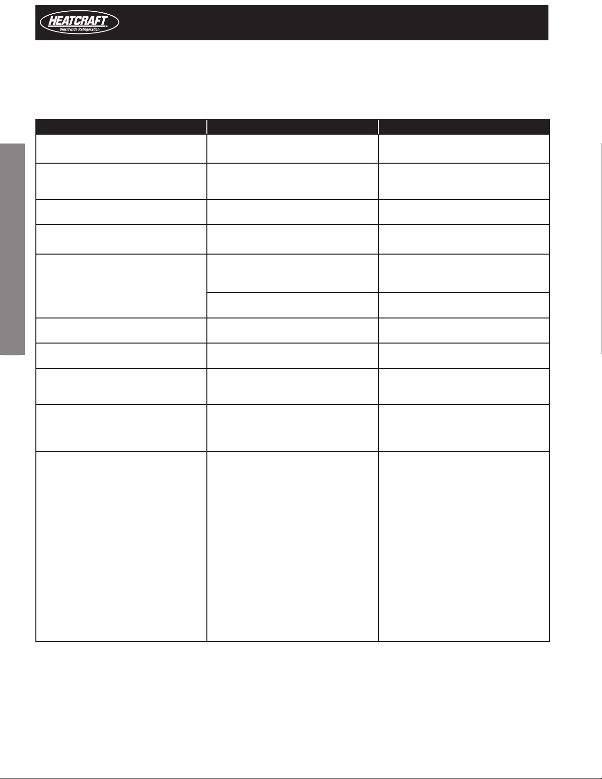
Troubleshooting
The following table shows a number of situations that may occur on the various models.
The most frequent causes and corresponding checks are described:
Problem Cause Checks
2. Controllers
the compressor does not start (signalled by
the compressor LED ashing)
the temperature is over the set limits but
there is no alarm message and the buzzer, if
tted, does not sound
alarm IA is signalled (multifunction input)
without actually being active
the alarm connected to the multifunction
input is not detected
the defrost is not activated defrost duration too short (dP)
the manual defrost is not activated and the
defrost LED ashes
the high temperature alarm is shown after a
defrost
the display remains frozen even after the
defrost
after modifying a parameter the controller
continues working with the old values
The evaporator fan does not start. 1. a compressor and fan start delay has been
• compressor delay set defrost post
• dripping in progress
alarm delay set parameters Ad, c6, d8
the multifunction input generates an alarm
when the contact opens
alarm delay set or parameter programming
error
interval between defrosts dI=0: in this case
the defrost is not activated
the end defrost temperature is too low or the
evaporator temperature is too high
compressor protection times set parameter d9 (select d9=1)
the alarm delay after defrost is too short or
the alarm threshold is too low
the ambient temperature has not yet reached
the set point or alternatively the time d8 has
not elapsed
the instrument has not updated the old
value or alternatively the parameter setting
procedure has not been ended correctly by
pressing the SET button for 3 s
set
2. if F0=1 (fan managed by fan controller)
• the evaporator is “hot”: the evaporator
temperature can be read by selecting
parameter /d;
• dripping in progress;
• F1 (evaporator fan control set point) too
low.
• post-dripping delay set
3. if F0=0
• F2=1 and the compressor is o
• dripping in progress
• post-dripping in progress
Installation and Operations Manual
parameters c0, c1 and c2 and dd
connection of the input and whether this is
closed in normal operation
1. if A4=1
2. the status of digital input A7
parameters dP and dI
parameters dt and d/ (defrost probe)
parameters d8 and AH
wait or reduce d8
turn the instrument o and on again or
alternatively reprogram the parameters
correctly
1. parameter c0
2. parameters F0, F1, Fd, dd and d/
3. parameters F0, F2, dd and Fd
16
Page 17
PRO3 Top Mount Packaged Refrigeration System | Indoor
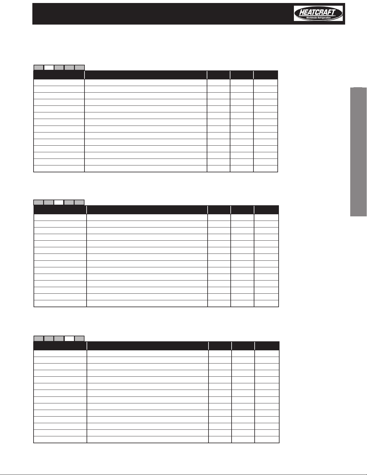
Device Setup
Set 1 - Low Temperature Models - L6 w/ -10° F Set Point
Set o Set 1 S et 2 Set 3 Set 4
Parameter Description Min Max Default
St Set point -30 30 -10
r1 Minimum set point value -50 303 -30
r2 Maximum set point value -30 150 30
c2 Minimum compressor o time 0 100 4
do Type of Defrost 0 4 0
dI Interval between defrost 0 199 6
dt End defrost temperature set point -50 127 65
dP Maximum defrost duration ALARM_ED 1 199 60
d4 Defrost on power-up 0 1 1
dd Dripping time 0 15 2
F0 Enable evaporator fan control 0 1 0
F2 Stop evaporator fan if compressor o 0 1 0
F3 Evaporator fan status during defrost 0 1 1
Fd Post-dripping time 0 15 2
2. Controllers
Set 2 - Medium Temperature Models M6 w/ 34° F Set Point
Set o Set 1 Set 2 Set 3 Set 4
Parameter Description Min Max Default
St Set point 0 50 34
r1 Minimum set point value -50 50 0
r2 Maximum set point value 0 150 50
c2 Minimum compressor o time 0 100 4
do Type of Defrost 0 4 0
dI Interval between defrost 0 199 6
dt End defrost temperature set point -50 127 65
dP Maximum defrost duration ALARM_ED 1 199 60
d4 Defrost on power-up 0 1 1
dd Dripping time 0 15 2
F0 Enable evaporator fan control 0 1 0
F2 Stop evaporator fan if compressor o 0 1 0
F3 Evaporator fan status during defrost 0 1 1
Fd Post-dripping time 0 15 0
Set 3 - High Temperature Models - H6 w/ 38° F Set Point
Set o Set 1 Set 2 Set 3 Set 4
Parameter Description Min Max Default
St Set point 0 50 38
r1 Minimum set point value -50 50 0
r2 Maximum set point value 0 150 50
c2 Minimum compressor o time 0 100 4
do Type of Defrost 0 4 2
dI Interval between defrost 0 199 6
dt End defrost temperature set point -50 127 40
dP Maximum defrost duration ALARM_ED 1 199 40
d4 Defrost on power-up 0 1 0
dd Dripping time 0 15 0
F0 Enable evaporator fan control 0 1 0
F2 Stop evaporator fan if compressor o 0 1 0
F3 Evaporator fan status during defrost 0 1 0
Fd Post-dripping time 0 15 0
17
Page 18

3. Service Information
Installation and Operations Manual
Table 8. System Troubleshooting Chart
PROBLEM POSSIBLE CAUSES POSSIBLE CORRECTIVE STEPS
Compressor 1. Main switch open. 1. Close switch.
will not run 2. Fuse blown. 2. Check electrical circuits and motor winding for shorts or grounds.
Investigate for possible overloading. Replace fuse after fault is corrected.
3. Thermal overloads tripped. 3. Overloads are automatically reset. Check unit closely when unit comes
back on line.
4. Defective contactor or coil. 4. Repair or replace.
5. System shut down by safety devices. 5. Determine type and cause of shutdown and correct it before resetting
safety switch.
6. No cooling required. 6. None. Wait until calls for cooling.
7. Motor electrical trouble. 7. Check motor for open windings, short circuit or burn out.
8. Loose wiring. 8. Check all wire junctions. Tighten all terminal screws.
Compressor 1. Flooding of refrigerant into crankcase. 1. Check setting of expansion valves.
noisy or vibrating 2. Worn compressor. 2. Replace.
High 1. Non-condensables in system. 1. Remove the non-condensables.
discharge 2. Fan not running. 2. Check electrical circuit. Replace if motor fails.
pressure 3. Dirty condenser coil. 3. Clean.
4. System overcharged with refrigerant. 4. Reclaim refrigerant and recharge proper amount.
Low discharge 1. Insucient refrigerant in system. 1. Check for leaks. Repair and add charge.
pressure 2. Low suction pressure. 2. See corrective steps for low suction pressure.
High suction 1. Excessive load. 1. Reduce load or add additional equipment.
pressure 2. Expansion valve overfeeding. 2. Check remote bulb. Regulate superheat.
Low 1. Lack of refrigerant. 1. Check for leaks. Repair and add charge (see refrigerant charge chart).
suction 2. Evaporator dirty or iced. 2. Clean.
pressure 3. Expansion valve malfunctioning. 3. Check and reset for proper superheat.
4. Condensing temperature too low. 4. Check ambient temperature 50°F to 100°F.
Compressor 1. Operating beyond design conditions. 1. Add equipment so that conditions are within allowable limits.
thermal protector 2. Dirty condenser coil. 2. Clean coil.
switch open 3. Overcharged system. 3. Reduce charge (see refrigerant charge).
Fan(s) will 1. Main switch open. 1. Close switch.
not operate 2. Blown fuses. 2. Replace fuses. Check for short circuits or overload conditions.
3. Defective motor. 3. Replace motor.
4. Defective defrost control. 4. Replace defective component.
5. Unit in defrost cycle. 5. Wait for completion of cycle.
6. Coil does not get cold enough to reset thermostat 6. Adjust fan delay setting of control.
Room 1. Control cut out set too high. 1. Adjust control.
temperature 2. Superheat too high. 2. Adjust thermal expansion valve.
too high 3. System low on refrigerant. 3. Add refrigerant. See refrigerant charge chart. See page 2.
4. Coil iced-up. 4. Manually defrost coil. Check defrost controls for malfunction.
Ice accumulating 1. Defrost duration is too long. 1. Adjust defrost termination temp on control.
on ceiling around 2. Fan delay not delaying fans after defrost period. 2. Adjust fan delay setting or replace bad sensor.
evaporator and/or 3. Defective defrost control or sensor. 3. Replace defective control or sensor.
on fan guards' 4. Too many defrosts. 4. Adjust number of defrosts.
venturi or blades
Coil not clearing 1. Coil temperature not getting above freezing 1. Check heater operation.
of frost during point during defrost.
defrost cycle. 2. Not enough defrost cycles per day. 2. Adjust control for more defrost cycles.
3. Defrost cycle too short. 3. Adjust defrost control, defrost duration setting.
4. Defective defrost control or sensor. 4. Replace defective component. .
Ice accumulating 1. Defective heater. 1. Replace heater.
in drain pan 2. Unit not installed properly (out of level) 2. Check and adjust if necessary.
3. Drain line plugged. 3. Clean drain line.
4. Defective control. 4. Replace defective component.
18
Page 19

PRO3 Top Mount Packaged Refrigeration System | Indoor
Replacement Parts by
Commercial Refrigeration Parts
Right source. Right parts. Right now.
InterLink™ is your link to a complete line of dependable and certied
commercial refrigeration parts, accessories and innovative electronic
controls for all Heatcraft Refrigeration Products equipment. At InterLink,
we provide our wholesalers with a comprehensive selection of product
solutions and innovative technologies for the installed customer base. And
every product is built to ensure the same high performance standards with
which all Heatcraft Refrigeration brands are built — backed by a dedicated
team to serve every customer need, delivering at the best lead times in the
industry.
Dependable. Versatile. Courteous.
Finally, one simple source for all your replacement needs from a name you
can trust.
For parts, please visit www.interlinkparts.com or call (800) 686-7278.
High Temp Med Temp Low Temp
Part Description Part #
PTN 021L6B^
PTN 031L6B^
PTN 019L6A^
PTN 050H6B^
PTN 067H6B^
PTN 076H6B^
PTN 104H6B^
PTN 133H6B^
PTN 104H6C^
PTN 026H6A^
PTN 031H6A^
PTN 042H6A^
PTN 050H6A^
Evaporator 22901901 1 1 2 2 3 3 3 3 1 1 2 2 3 3 3 3 1 1 2 2 3 3 3 3
Evaporator 23100501 1 1 1 1 1 1 1
Condenser 5110E 1 1 1 1 2 2 2 2 1 1 1 1 2 2 2 2 1 1 1 1 2 2 2 2
Fan Blades
Condenser 22900601 1 1 1 1 1 1 1
Evaporator (115V) EC 25319301 1 1 1 1 1 1 1
Evaporator (115V) EC 25319401 1 1 1
Evaporator (115 V) PSC 25308501 1 1 1 1 1 1 1 1 1 1
Evaporator (230) EC 25319501 1 2 2 3 3 3 3 1 2 2 3 3 3 3 1 2 2 3 3 3 3
Evaporator (230) PSC 25308601 1 2 2 3 3 3 3 1 2 2 3 3 3 3 1 2 2 3 3 3 3
CONDENSER (230V) 2537801 1 1
CONDENSER (115 V) 25399201 1 1 1 1 1 1 1 1
CONDENSER (115 V) 25308501 1 1 1 1 1 1 1 1 1 1
CONDENSER (230V) 25308601 1 1 1 2 2 2 2 1 1 1 2 2 2 2 1 1 1 2 2 2 2
Fan Motors
CONDENSER (230V) EC 25319501 2 2 2
Evap Fan Motor Bracket 4000104 1 1 2 2 3 3 3 3 1 1 2 2 3 3 3 3 1 1 2 2 3 3 3 3
Evap Fan Motor Bracket 23101401 1 1 1 1 1 1 1
Cond Fan Motor Bracket 23103301 1 1 1 1 2 2 2 2 1 1 1 1 2 2 2 2 1 1 1 1 2 2 2 2
Cond Fan Motor Bracket 23101101 1 1 1 1 1 1 1
25A, 208-230 2259996 1 1 1 1 1 1
20A, 115V 2252403 1 1 1 1 1 1 1 1 1 1
20A, 230V R034915200 1 1 1 1 1 1 1 1 1 1 1 1 1 1 1
Contactors
Heater Limit Thermostat 5708L 1 1 1 1 1 1 1 1 1 1 1 1 1 1 1 1 1 1 1 1
Temp Control Kit
(208-230V)
Temp. Control
Temp Control Kit (115 V) 89994802 1 1 1 1 1 1 1 1 1 1
Defrost Heaters (115V) 24751901 1 1 1 1
Defrost Heaters (115V) 24712101 3 3
Defrost Heaters (230V) 4312F 3 3 3 3 3 3
Defrost Heaters (230V) 4313F 3 3 3 3 3 3 3 3
Defrost Heaters
89994801 1 1 1 1 1 1 1 1 1 1 1 1 1 1 1 1 1 1 1 1 1
PTN 133H6C^
PTN 024M6A^
PTN 029M6A^
PTN 047M6B^
PTN 040M6A^
PTN 063M6B^
PTN 047M6A^
PTN 072M6B^
PTN 099M6B^
PTN 128M6B^
PTN 099M6C^
PTN 021L6A^
PTN 128M6C^
^This space may be blank or completed with an H designation indicating PSC motors, or an E for EC Motors on evaporators
PTN 044L6B^
PTN 052L6B^
PTN 069L6B^
PTN 052L6C^
PTN 069L6C^
3. Service Information
19
Page 20
Small Cabinet Models Wiring. 230/1/60/
Cooler/Freezer- Electric Defrost
Installation and Operations Manual
Diagram 1. Wiring Diagram for
Low /Medium Temperature Wiring.
System, Electric Defrost
5. Wiring Information
20
Page 21
PRO3 Top Mount Packaged Refrigeration System | Indoor
Small Cabinet Models Wiring. 115/1/60 voltage.
Air Defrost Systems
Diagram 2. Wiring Diagram for
115/1/60 model High Temperature Wiring.
System, Air Defrost
21
5. Wiring Information
Page 22
Installation and Operations Manual
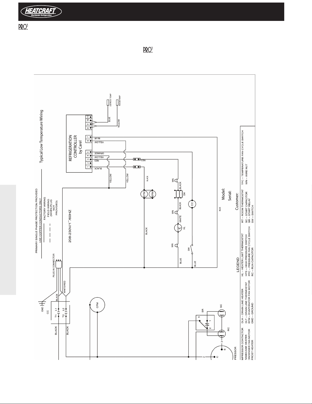
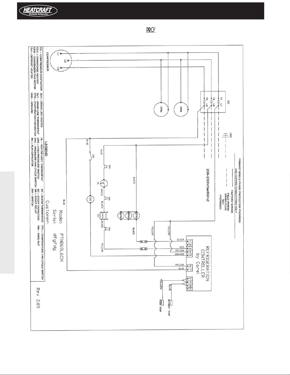
Diagram 3. Wiring Diagram for
Medium/Low Temperature Wiring.
System, Electric Defrost
5. Wiring Information
22
Page 23

PRO3 Top Mount Packaged Refrigeration System | Indoor
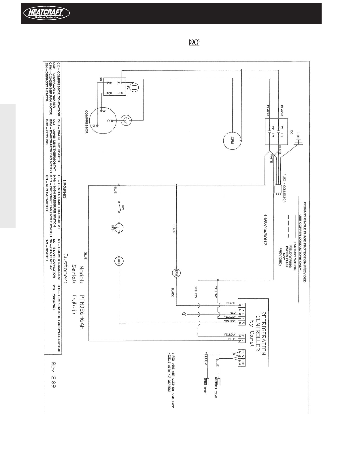
Diagram 4. Wiring Diagram for System, Electric Defrost
115/1/60 model Low Temperature Wiring.
5. Wiring Information
23
Page 24
Installation and Operations Manual
5. Wiring Information
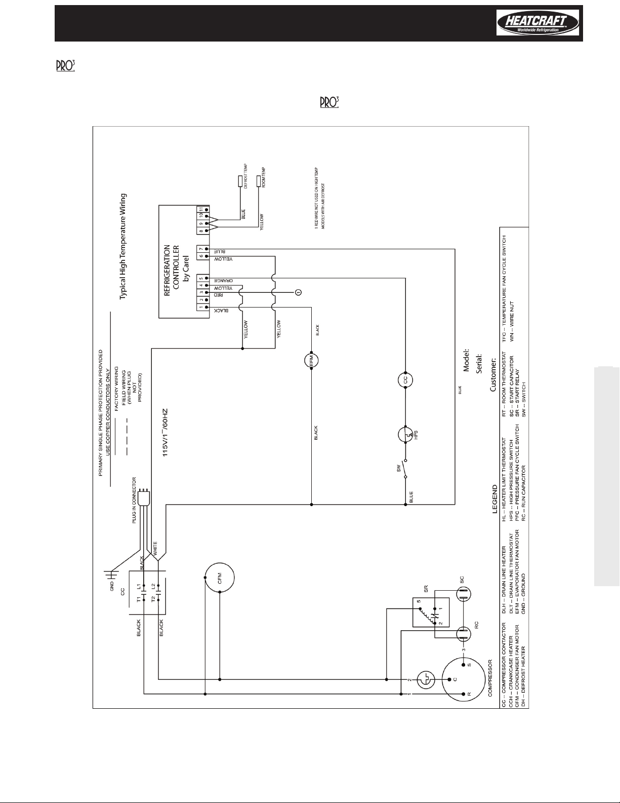
Diagram 5. Wiring Diagram for
115/1/60 model High Temperature Wiring.
System Air Defrost
24
Page 25

PRO3 Top Mount Packaged Refrigeration System | Indoor
Diagram 6. Wiring Diagram for System, Electric Defrost
115/1/60 model Medium Temperature Wiring.
5. Wiring Information
25
Page 26

Warranty Statement
Heatcraft Refrigeration Products LLC warrants to its direct purchasers
that the
Refrigeration Products LLC shall be of a merchantable quality, free of
defects in material or workmanship, under normal use and service
for a period of two (2) years from date of original installation, or
thirty (30) months from date of shipment by Heatcraft Refrigeration
Products LLC, whichever rst occurs. Service Parts, for product out
of original warranty, should be so warranted for a period of twelve
(12) months from date of shipment. Any product covered by this
order found to Heatcraft Refrigeration Products LLC's satisfaction to
be defective upon examination at Heatcraft Refrigeration Products
LLC's factory will, at Heatcraft Refrigeration Products LLC's option,
be repaired or replaced and returned to Buyer via lowest common
carrier, or Heatcraft Refrigeration Products LLC may at its option grant
Buyer a credit for the purchase price of the defective article. Upon
return of a defective product to Heatcraft Refrigeration Products LLC's
plant, freight prepaid, by Buyer, correction of such defect by repair
or replacement, and return freight via lowest common carrier, shall
constitute full performance by Heatcraft Refrigeration Products LLC
of its obligations hereunder.
Hermetic compressors furnished by Heatcraft Refrigeration Products
LLC are subject to the standard warranty terms set forth above, except
that motor compressor replacements or exchanges shall be made
through the nearest authorized wholesaler of the motor compressor
manufacturer (not at Heatcraft Refrigeration Products LLC's factory)
and no freight shall be allowed for transportation of the motor
compressor to and from the wholesaler. The replacement motor
compressor shall be identical to the model of the motor compressor
being replaced. Additional charges which may be incurred throughout
the substitution of other than identical replacements are not covered
by this warranty.
The foregoing is in lieu of all other warranties, express or implied,
notwithstanding the provisions of the uniform commercial code, the
Magnuson-Moss Warranty-Federal Trade Commission Improvement
Act, or any other statutory or common law, federal or state.
Heatcraft Refrigeration Products LLC makes no warranty expressed or
implied, of tness for any particular purpose, or of any other nature
whatsoever, with respect to products manufactured or sold by
Heatcraft Refrigeration Products LLC hereunder, except as specically
set forth above and on the face hereof. It is expressly understood and
agreed that Heatcraft Refrigeration Products LLC shall not be liable to
buyer, or any customer of Buyer, for direct or indirect, special, incidental,
consequential or penal damages, or for any expenses incurred by
reason of the use or misuse by Buyer or third parties of said products.
To the extent said products may be considered "Consumer Products,'
as dened in Section 101 of the Magnuson-Moss warranty-Federal
Trade Commission Improvement Act, Heatcraft Refrigeration Products
product, except Service Parts, manufactured by Heatcraft
Installation and Operations Manual
LLC makes no warranty of any kind, express or implied, to "Consumers,"
except as specically set forth above and on the face hereof.
This equipment is designed to operate properly and produce the
rated capacity when installed in accordance with good refrigeration
industry practices.
The following conditions should be adhered to when installing this
unit to maintain the manufacturers warranty:
(a) The power supply to the unit must meet the
following conditions:
A. Three phase voltages must
be +/- 10% of nameplate
ratings. Single phase must be
within +10% or -5% of
nameplate ratings.
B. Phase imbalance cannot
exceed 2%.
(b) All control and safety switch circuits must be
properly connected according to the wiring
diagram.
(c) The factory installed wiring must not be
changed without written factory approval.
Optional Three-Year Extended Compressor Warranty
The Equipment Dealer may purchase for the Owner at the time of the
original invoice of the equipment a Three-Year Limited Replacement
Compressor Warranty. This entitles the owner to be reimbursed for the
cost of a replacement compressor, during the third through fth year
of the life of the compressor.
The warranty program functions similarly to the standard warranty
oered. When a compressor failure occurs and the unit is exchanged
"over the counter" at the authorized wholesaler outlet a salvage credit
is issued along with the invoice for the new compressor. Return copies
of both the credit and invoice to the Equipment Dealer along with
the model and serial number of the condensing unit. The Equipment
Dealer will process this claim with the Manufacturer and subsequently
reimburse the Owner for the cost of the new compressor.
This warranty covers the actual compressor only and does not extend
to any labor, trip charges, crane rental, taxes or additional parts,
refrigerant or processing/handling charges required to make the
unit operational.
26
Page 27

PRO3 Top Mount Packaged Refrigeration System | Indoor
Notes:
27
Page 28

The name behind the brands you trust.
Heatcraft Refrigeration Products, LLC
2175 West Park Place Blvd., Stone Mountain, GA 30087
P: (800) 321-1881 • www.heatcraftrpd.com
Since product improvement is a continuing eort, we reserve the right to make changes in specications without notice.
H-IM-81E-0910 | Version 000
 Loading...