


|
|
|
|
MAC Series |
|
|
|
|
|
|
Condensing Units |
|
|
|
|
|
|
|
|
|
|
|
|
|
|
|
|
H-IM-67G |
December, 2003 |
Part #25006401 |
|
|||
Replaces H-IM-67F (12/03) |
|
|
|
|
||
Installation and Operation Manual |
|
|||||
|
|
|
|
|
|
|
|
|
|
|
TABLE of CONTENTS |
|
|
|
|
|
|
General safety and inspection |
|
|
|
|
|
|
Condensing unit specifications |
2 |
|
|
|
|
|
Evaporator unit specifications ................................. |
3 |
|
|
|
|
|
Evaporator placement ............................................. |
4 |
|
|
|
|
|
Refrigerant piping and line sizes .......................... |
6-8 |
|
|
|
|
|
Leak detection and evacuation ............................... |
9 |
|
|
|
|
|
Field wiring ............................................................ |
10 |
|
|
|
|
|
Beacon II Controller |
|
|
|
|
|
|
Installation ........................................................... |
11 |
|
|
|
|
|
Refrigerant line brazing |
|
|
|
|
|
™ |
Power supply |
|
|
|
|
|
Wiring |
12 |
|
|
|
|
|
|
|
||
|
|
|
|
Box temp control settings |
|
|
|
|
|
|
Refrigerant charging |
|
|
|
|
|
|
..............................................Start-up operation |
13 |
|
|
|
|
|
|
||
|
|
|
|
Initial power on |
|
|
|
|
|
|
Operating mode display ..................................... |
14 |
|
|
|
|
|
Program & review settings/changes .................. |
15-19 |
|
|
|
|
|
Low ambient operation |
|
|
|
|
|
|
Pumpdown .................................................... |
19-20 |
|
|
|
|
|
Defrost ................................................................ |
20 |
|
|
|
|
|
Alarms and error indicator LED .......................... |
21 |
|
|
|
|
|
Evaporator fans shut down by operators |
|
|
|
|
|
|
Power failure |
|
|
|
|
|
|
Service mode |
|
|
|
|
|
|
Space sensor terminal |
|
|
|
|
|
|
Checking sensors ............................................... |
22 |
|
|
|
|
|
System defaults |
|
|
|
|
|
|
Control sensor and piping .................................. |
23 |
|
|
|
|
|
Checking operation of exp. valve |
|
|
|
|
|
|
Exp. valve motor winding resistance .................. |
24 |
|
|
|
|
|
Smart Controller ............................................ |
25-36 |
|
|
|
|
|
Operational checkout ......................................... |
37 |
|
|
|
|
|
Preventive maintenance................................ |
38-40 |
|
|
|
|
|
Diagnostics ....................................................... |
41-44 |
|
|
|
|
|
Beacon II parts lists .......................................... |
45-46 |
|
|
|
|
|
Startup Checklist .............................................. |
47-48 |
|
|
|
|
|
Wiring diagrams ............................................... |
49-51 |
|
|
|
|
|
Warranty information ............................................. |
52 |
|
|
|
|
|
|
|
|
General Safety Information
General Safety Information
1.Installation and maintenance to be performed only by certified personnel who are familiar with this type of equipment.
2.Make sure that all field wiring conforms to the requirements of the equipment and all applicable national and local codes.
3.Avoid contact with sharp edges and coil surfaces. They are a potential injury hazard.
4.Make sure all power sources are disconnected before any service work is done on units.
WARNING: Refrigerant can be harmful if it is inhaled. Refrigerant must be used and recovered responsibly. Failure to follow this warning may result in personal injury or death.
Inspection
Responsibility should be assigned to a dependable individual at the job site to receive material. Each shipment should be carefully checked against the bill of lading. The shipping receipt should not be signed until all items listed on the bill of lading have been accounted for. Check carefully for concealed damage. Any shortage or damages should be reported to the delivering carrier. Damaged material becomes the delivering carrier’s responsibility and should not be returned to the manufacturer unless prior approval is given to do so. When uncrating, care should be taken to prevent damage. Heavy equipment should be left on its shipping base until it has been moved to the final location.
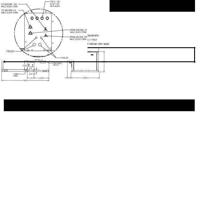
Condensing Unit Specifications
Figure 1.
Table 1. Condensing Unit Specifications
|
|
|
|
|
|
|
|
|
Receiver |
|
Model |
Location |
Compressor |
|
Voltage |
HP |
Unit |
Unit |
Unit |
90% full |
|
|
|
|
|
|
|
MCA |
MOP |
kW |
lbs. |
|
MAC3X |
Freezer |
ZF09K4E |
208-230/3/60 |
1 1/2 |
26.9 |
35.0 |
4.3 |
9.0 |
||
Cooler |
RS64C1E |
208-230/1/60 |
3/4 |
9.0 |
||||||
|
|
|
|
|||||||
MAC4X |
Freezer |
ZF13K4E |
208-230/3/60 |
3 |
28.8 |
40.0 |
6.3 |
9.0 |
||
|
|
|
|
|
|
|||||
Cooler |
RS43C1E |
208-230/1/60 |
1/2 |
9.0 |
||||||
|
|
|
|
|||||||
MAC5X |
Freezer |
ZF15K4E |
208-230/3/60 |
3 1/2 |
36.2 |
50.0 |
6.4 |
14.0 |
||
Cooler |
RS43C1E |
208-230/1/60 |
1/2 |
9.0 |
||||||
|
|
|
|
|||||||
MAC7X |
Freezer |
ZF13K4E |
208-230/3/60 |
3 |
33.8 |
45.0 |
6.4 |
9.0 |
||
Cooler |
CS10K6E |
208-230/1/60 |
1 1/2 |
9.0 |
||||||
MAC8X |
Freezer |
ZF15K4E |
208-230/3/60 |
3 1/2 |
41.0 |
50.0 |
6.5 |
14.0 |
||
Cooler |
CS10K6E |
208-230/1/60 |
1 1/2 |
9.0 |
||||||
MCA = Minimum Circuit Ampacity MOP = Maximum Overcurrent Protection |
|
|
|
|||||||
Note: Remote circuits internal volume = .10 cu. ft. |
Approximate unit weight = 825 lbs. |
|
|
|||||||
2

Evaporator Unit Specifications
Table 2. Evaporator Unit Specifications
|
Evaporator Model |
Location |
Cap. |
No. of |
Dimensions (in.) |
Connections (In.) |
Amps |
Weight |
||||
|
|
|
BTUH |
Fans |
A |
B |
Suct. ID |
Liq. OD |
Mtrs. |
Htrs. |
(lbs.) |
|
MAC3X |
ADT070BHB2N6MK |
Cooler |
7,000 |
2 |
45.50 |
33.25 |
7/8 |
1/2 |
1.0 |
— |
45 |
|
LET090BHB2N6MK |
Freezer |
9,000 |
2 |
45.50 |
33.25 |
7/8 |
1/2 |
1.0 |
7.8 |
48 |
||
|
||||||||||||
MAC7X |
ADT104BHB2N6MK |
Cooler |
10,400 |
2 |
45.50 |
33.25 |
7/8 |
1/2 |
1.0 |
— |
49 |
|
LET120BHB2N6MK |
Freezer |
12,000 |
3 |
61.50 |
49.25 |
7/8 |
1/2 |
1.5 |
11.7 |
60 |
||
|
||||||||||||
MAC8X |
ADT104BHB2N6MK |
Cooler |
10,400 |
2 |
45.50 |
33.25 |
7/8 |
1/2 |
1.0 |
— |
49 |
|
LET160BHB2N6MK |
Freezer |
16,000 |
4 |
77.50 |
65.25 |
1 1/8 |
1/2 |
2.0 |
15.7 |
81 |
||
|
||||||||||||
MAC4X |
ADT052BHB2N6MK |
Cooler |
5,200 |
1 |
45.50 |
17.25 |
5/8 |
1/2 |
0.5 |
— |
31 |
|
LET120BHB2N6MK |
Freezer |
12,000 |
3 |
61.50 |
49.25 |
7/8 |
1/2 |
1.5 |
11.7 |
60 |
||
|
||||||||||||
MAC5X |
ADT052BHB2N6MK |
Cooler |
5,200 |
1 |
29.50 |
17.25 |
5/8 |
1/2 |
0.5 |
— |
31 |
|
LET160BHB2N6MK |
Freezer |
16,000 |
4 |
77.50 |
65.25 |
1 1/8 |
1/2 |
2.0 |
15.7 |
81 |
||
|
||||||||||||
Figure 2.
© 2002 Heatcraft Refrigeration Products LLC
3

Evaporator Placement
Figure 3. Evaporator Placement In Cooler/Freezer |
|
|||
Loading Door |
|
|
Loading Door |
|
1 |
1 |
|
|
|
Freezer |
Cooler |
or |
Freezer |
Cooler |
|
|
|
1 |
1 |
Note: Whenever possible always try to position the evaporator to blow towards the walk-in door. Never position the evaporator over or adjacent to a door opening.
Evaporator Minimum Unit Clearance
1 1/2 H
Top View |
1 1/2 H |
|
|
|
1 1/2 H |
|
|
|
|
|
|
|
|
|
|
|
|
|
|
|
|
|
|
|
|
|
|
|
|
H = Total Height of Unit’s Coil Surface
1 1/2 H
H
Side View
2 H
1/2 W |
1/2 W |
|
W |
4

Condensing Unit Placement
Space and Location Requirements
The most important consideration which must be taken into account when deciding upon the location of aircooled equipment is the provision for a supply of ambient air to the condenser, and removal of heated air from the condensing unit or remote condenser area. Where this essential requirement is not adhered to, it will result in higher head pressures, which cause poor operation and potential failure of equipment. Units must not be located in the vicinity of steam, hot air or fume exhausts. Corrosive atmospheres require custom designed condensers.
Another consideration which must be taken is that the unit should be mounted away from noise sensitive spaces and must have adequate support to avoid vibration and noise transmission into the building. Units should be mounted over corridors, utility areas, rest rooms and other auxiliary areas where high levels of sound are not an important factor. Sound and structural consultants should be retained for recommendations. (Refer to actual building plans for unit locations.)
Figure 4. |
|
|
|
|
|
|
|
|
|
|
|
|
|
3 Feet |
|
|
|
|
|
(minimum) |
|
|
|
|
|
Clearance = |
|
3 Feet |
|
3 Feet from |
|
|
|
||
|
|
|
(minimum) |
||
Building |
|
|
|||
|
|
Clearance to |
|||
Wall |
|||||
|
an Open Block |
||||
|
|
||||
|
|
|
|
Wall or |
|
|
|
|
|
Shrubs. |
|
|
|
|
3 Feet |
|
|
|
|
|
|
||
|
|
|
(minimum) |
|
|
|
|
|
Clearance for |
|
|
|
|
|
Contractor to |
|
|
|
|
|
Service Unit. |
|
5

Refrigeration Piping And Line Sizing
Refrigeration Piping And Line Sizing
The system as supplied by Bohn/Heatcraft, was thoroughly cleaned and dehydrated at the factory. Foreign matter may enter the system by way of the evaporator to condensing unit piping. Therefore, care must be used during installation of the piping to prevent entrance of foreign matter. Install all refrigeration system components in accordance with applicable local and national codes and in conformance with good practice required for the proper operation of the system. The interconnecting pipe size is not necessarily the same size as the stub-out on the condensing unit or the evaporator.
The following procedures should be followed:
(a)Do not leave dehydrated compressors or filter-driers on condensing units open to the atmosphere any longer than is absolutely necessary.
(b)Use only refrigeration grade (ACR) copper tubing, properly sealed against contamination.
(c)Suction lines should slope 1/4” per 10 feet towards the compressor (in direction of flow).
(d)Suitable P-type oil traps should be located at the base of each suction riser to enhance oil return to the compressor.
(e)For desired method of superheat measurement, a pressure tap should be installed in each evaporator suction line in the proximity of the expansion valve bulb.
(f)When brazing refrigerant lines, an inert gas should be passed through the line at low pressure to prevent scaling and oxidation inside the tubing. Dry nitrogen is preferred.
(g)Use only a suitable silver solder alloy on suction and liquid lines.
(h)Limit the soldering paste of flux to the minimum required to prevent contamination of the solder joint internally. Flux only the male portion of the connection, never the female. After brazing, remove excess flux.
(i)Remove temperature sensor attached to suction line on Beacon II systems before brazing of the solder joint internally. Flux only the male portion of the connection – never the female. After brazing, remove excess flux.
(j)Wrap expansion valves with wet rags during brazing to the liquid line.
CAUTION: If the temperature gets too high, these components may be damaged. Heat absorbing compounds or wet rags must be used to protect the expansion valve when brazing to the refrigerant piping/line connections, and the suction line sensor must be removed per above instructions.
(k)Do not use “bull head” tees. This will cause oil return problems and can cause poor performance.
(l)If isolation valves are installed at the evaporator, full port ball valves should be used.
Table 3. Recommended Line Size In Equivalent Lengths
Model |
Room |
Max. |
|
Max. Suction Line |
|
Liquid Line |
|||
|
|
Riser |
25’ |
50’ |
Plus 50’ |
25’ |
50’ |
Plus 50’ |
|
MAC3X |
Freezer |
7/8” |
7/8” |
7/8” |
Consult Factory |
3/8” |
3/8” |
Consult Factory |
|
Cooler |
5/8” |
5/8” |
5/8” |
Consult Factory |
3/8” |
3/8” |
Consult Factory |
||
|
|||||||||
MAC4X |
Freezer |
7/8” |
7/8” |
7/8” |
Consult Factory |
3/8” |
3/8” |
Consult Factory |
|
Cooler |
5/8” |
5/8” |
5/8” |
Consult Factory |
3/8” |
3/8” |
Consult Factory |
||
|
|||||||||
MAC5X |
Freezer |
1 1/8” |
7/8” |
1 1/8” |
Consult Factory |
3/8” |
3/8” |
Consult Factory |
|
Cooler |
5/8” |
5/8” |
5/8” |
Consult Factory |
3/8” |
3/8” |
Consult Factory |
||
|
|||||||||
MAC7X |
Freezer |
7/8” |
7/8” |
7/8” |
Consult Factory |
3/8” |
3/8” |
Consult Factory |
|
Cooler |
7/8” |
7/8” |
7/8” |
Consult Factory |
3/8” |
3/8” |
Consult Factory |
||
|
|||||||||
MAC8X |
Freezer |
1 1/8” |
7/8” |
1 1/8” |
Consult Factory |
3/8” |
3/8” |
Consult Factory |
|
Cooler |
7/8” |
7/8” |
7/8” |
Consult Factory |
3/8” |
3/8” |
Consult Factory |
||
|
|||||||||
Remote Precharged Circuits
The remote precharged circuits are provided with a factory holding charge of R-404A. The system charge is located in the appropriate drink and ice machines. Schrader valve fittings are provided for liquid line charging at the condensing unit. Consult the appropriate drink and ice machine manufacturers for details on installation of precharged lines.
6

Refrigeration Piping
Suction Lines
NOTE: If the suction line must rise to the point higher than the suction connection on the evaporator, a suction line trap at the outlet of the evaporator must be provided.
Horizontal suction lines should slope away from the evaporator toward the compressor at the rate of 1/4’ per 10 feet for good oil return.
Suction lines that are outside of refrigerated space must be insulated. See “Line Insulation” for more information.
Suction Line Risers
NOTE: To provide proper oil return, a suction trap must be provided at the base of all suction risers.
Prefabricated wrought copper traps are available, or a trap can be made by using two street ells and one regular ell. The suction trap must be the same size as the suction line. For long vertical risers, additional traps may be necessary. Generally, one trap is recommended for each length of pipe (approximately 20 feet) to insure proper oil movement. See Figure 5 below for methods of constructing proper suction line P-traps.
Figure 5. Suction P-traps
Condensate Drain Lines
Copper drain lines should be used and properly protected from freezing. In running drain lines, provide a minimum of 4 inches per foot pitch for proper drainage. Drain lines should be at least as large as the evaporator drain connection. All plumbing connections should be made in accordance with local plumbing codes. All condensate drain lines must be trapped, and run to an open drain. They must never be connected directly to the sewer systems. Traps in the drain line must
be located in a warm ambient. See Figure 6. We Figure 6. Drain Line recommend a trap on all evaporators. Traps located
outside, or extensive outside runs of drain line must be wrapped with a drain line heater. The heater should be connected so that it is continuously on. The drain line must be insulated to prevent heat loss. A heat input of 20 watts per lineal foot of drain line for 0ºF (-18° C) room applications and 30 watts per lineal foot for -20° F (-29° C) rooms is satisfactory.
Inspect the drain pan periodically to insure free drainage of condensate. If the drain pan contains standing water, check for proper installation. The drain pan should be cleaned regularly with warm soapy water.
WARNING: All power must be disconnected before cleaning. The drain pan also serves as
NOTE: Always trap drain lines individually
cover for hazardous moving parts. Operation of unit without drain pan constitutes a hazard.
to prevent vapor migration.
7

Refrigeration Piping
Figure 7. Example of Pipe Support
1.Normally, any straight run of tubing must be supported in at least two locations near each end of the run. Long runs require additional supports. The refrigerant lines should be supported and fastened properly. As a guide, 3/8 to 7/8 should be supported every 5 feet, 1-1/8 and 1-3/8 every 7 feet; and 1-5/8 and 2-1/8 every 9 to 10 feet.
2.When changing directions in a run of tubing, no corner should be left unsupported. Supports should be placed a maximum of 2 feet in each direction from the corner.
3.Piping attached to a vibrating object (such as a compressor or compressor base) must be supported in such a manner that will not restrict the movement of the vibrating object. Rigid mounting will fatigue the copper tubing.
4.Do not use short radius ells. Short radius elbows have points of excessive stress concentration and are subject to breakage at these points.
5.Thoroughly inspect all piping after the equipment is in operation and add supports wherever line vibration is significantly greater than most of the other piping. Extra supports are relatively inexpensive as compared to refrigerant loss.
Figure 8.
Mac
Unit
Line Insulation
After the final leak test, refrigerant lines exposed to high or low ambient conditions should be insulated to reduce heat loss or gain and prevent the formation of flash gas in the liquid lines. Suction lines must be insulated with 3/4’ wall Armstrong “Armaflex” or equivalent. Liquid lines must be insulated with 1/2-inch wall insulation or better. The insulation located in outdoor environments should be protected from UV exposure to prevent deterioration of insulating value.
8

Leak Detection And Evacuation
Leak Detection
After all lines are connected, the entire system must be leak tested. The complete system should be pressurized to not more than 150 psig with refrigerant and dry nitrogen. The use of an electronic type of leak detector is highly recommended because of its greater sensitivity to small leaks. As a further check, it is recommended that this pressure be held for a minimum of 12 hours and then rechecked. For a satisfactory installation, the system must be leak tight.
Within the last several years, manufacturers have developed fluorescent dye leak detection systems for use with refrigerants. These dyes mix with the lubricant and, when exposed to an ultraviolet light “fluoresce,” indicate the location of leaks. Copeland has tested and approved the Rigid “System Safe” dye and found it to be compatible with the compressor materials in systems.
Evacuation
CAUTION: Do not use the refrigeration compressor to evacuate the system. Do not start the compressor while it is in a vacuum.
It is of the utmost importance that proper system evacuation and leak detection procedures be employed. Copeland recommends a minimum evacuation to 500 microns. In addition, a vacuum decay test is strongly recommended to assure there is not a large pressure differential between the system and vacuum pump. Good evacuation processes include frequent vacuum pump oil changes and large diameter, short hose connections to both high and low sides of the system preferably using bronze braided hose.
A good, deep vacuum pump should be connected to both the low and high side evacuation valves with copper tube or high vacuum hoses (1/4” ID minimum). If the compressor has service valves, they should remain closed. A deep vacuum gauge capable of registering pressure in microns should be attached to the system for pressure readings.
A shut-off valve between the gauge connection and vacuum pump should be provided to allow the system pressure to be checked after evacuation. Do not turn off vacuum pump when connected to an evacuated system before closing shut-off valve.
The vacuum pump should be operated until a pressure of 1,500 microns absolute pressure is reached – at which time the vacuum should be broken with the refrigerant to be used in the system through a drier until the system pressure rises above “0” psig.
NOTE: Refrigerant used during evacuation can not be vented. Reclaim all used refrigerant. EPA regulations are constantly
being updated. Ensure your procedures follow correct regulations.
Repeat this operation a second time.
Open the compressor’s service valves and evacuate the entire system to 500 microns absolute pressure.
Raise the pressure to 2 psig with the refrigerant and remove the vacuum pump.
9

Field Wiring
WARNING: All wiring must be done in accordance with applicable codes and local ordinances.
The field wiring should enter the areas as provided on the unit. The wiring diagram for each unit is located on the inside of the electrical panel door. All field wiring should be done in a professional manner and in accordance with all governing codes. Before operating the unit, double check all wiring connections, including the factory terminals. Factory connections can vibrate loose during shipment.
1.The nameplate on the unit is marked with the electrical characteristic for wiring the unit.
2.Consult the wiring diagram in the unit cooler and in the condensing unit for proper connections.
3.Wire type should be of copper conductor only and of the proper size to handle the connected load.
4.The unit must be grounded.
Figure 9. Beacon II Board
Heater
Relay
Fan
Relay
LED
Display
Room
Sensor
Defrost
Sensor
Suction
Sensor
Suction
Pressure
Expansion
Valve
Connection
Selection
Buttons
24 V.
Terminal
Block
10
Beacon II Controller
Installation Tips
•Use a minimum 18 gauge wire for all low voltage connections.
•The Beacon II board get its 24 VAC power supply from a transformer mounted in the electrical end of each evaporator. On 208-240 volt systems the multi-tap transformer is shipped from our factory wired for 240 volts. If your supply voltage is 208 volt you must change to the 208 volt tap on the transformer.
•Refer to wiring schematic shipped on units for wiring.
•Evaporators are shipped from our factory with a preset box setpoint temperature of 35° F for air defrost and -10° F for electric defrost. If your box setpoint temperature requirements are different this must be set using directions outlined under “Room Temperature Control”.
•The suction line temperature sensor MUST be removed from the suction line before brazing the suction tubing. The sensor MUST then be reinstalled on the suction line after brazing is completed and the tubing has cooled. Insulate when finished.
•The low pressure switch time delay relay, located in the condensing unit, must be set to one minute.
•Some systems may require the crankcase heater to be energized 24 hours prior to start-up. The Beacon II should be de-energized for this period by placing it in the SERVICE MODE. This is done by pressing the “FORCE SERVICE” button twice. To start the system cooling, press the “CLEAR” button.
•Room sensors must be left connected on ALL evaporators.
•A pressure transducer is installed on the evaporator. Do not leak test system above 150 PSI or damage to transducer could occur.
•Refer to the Beacon II Smart Controller Installation Manual, shipped with the Beacon II Smart Controller, for installation, programming and monitoring information.
Condensing Unit
The condensing unit control panel contains the relays, contactors, and a terminal block which is appropriately marked to match the low voltage wiring connections. A sensor for outdoor air temperature measurement is installed on the condensing unit.
Condensing unit must be installed using proper refrigeration practices and codes. Make sure there is good airflow and good clearances around unit. See Figure 4, page 5.
Evaporator Unit
The evaporator contains the BEACON II controller(s), electric expansion valve(s), pressure transducer, distributor(s), orifice(s), transformer and three sensors. These components are all factory mounted and wired. The three sensors are factory mounted and provide input to the controller from the following: defrost temp., suction temp., room temp.
Each evaporator unit must be installed using proper refrigeration practices and codes. Make sure the piping is correctly sized and properly routed. Liquid and suction lines MUST be insulated. There must also be good clearance around the unit. See Figure 3, page 4.
11

Beacon II Controller
Refrigerant Line Brazing (CAUTION)
The electric expansion valve and the suction temperature sensor on the suction line are factory installed. Care must be taken when brazing these lines at the evaporator. Too high a temperature may destroy these components. Heat absorbing compounds or “wet rags” must be used when brazing the refrigerant line connections. The suction line sensor should be removed before brazing.
Power Supply
The Beacon II board gets its 24 VAC power supply from a transformer mounted in the electrical end of each evaporator. On 208-240 volt systems the multi-tap transformer is shipped from our factory wired for 240 volts. If your supply voltage is 208 volt you must change to the 208 volt tap on the transformer.
VERY IMPORTANT: If the supply voltage to the evaporator is 208 volts, the primary tap of the transformer must be moved to the 208 volt tap. This must be done for all the evaporators on that system.
If the 24 VAC power supply falls below 18 VAC the system may power down and shut off. When the power supply is corrected to 24 VAC the system will restart after the four minute hold-off period and resume normal operation.
Wiring
Wiring between the condensing unit and the unit cooler(s) will be as follows (see attached wiring diagrams):
•High voltage – There may be high voltage on the defrost heater relay and the fan relay. See unit cooler spec. plate for ampacity.
•Low voltage – 24V Class II control circuit. A total of five low voltage leads are required to connect the condensing unit to the evaporator (see wiring diagram). Two of these leads are for connecting the outdoor temperature sensor. The other three leads are for connecting the compressor relay, service relay and 24V Common inputs. All 24 volt wiring must be run separate from the line voltage wiring.
•Number of wires in low voltage wiring bundles:
MAC to cooler evaporator - 5
MAC to freezer evaporator - 5
Cooler evaporator to Smart Controller - 6
Freezer evaporator to Smart Controller - 4
• Low voltage wiring must be 18 gauge minimum. For low voltage wiring, maximum distances are:
Condensing unit to evaporator |
500 ft. |
Smart Controller to evaporator |
1,000 ft. |
•Alarm circuit – The onboard alarm is a dry set of NC contacts which closes to indicate an alarm. The type and wiring for the alarm is customer specified. Note that the alarm circuit does not distinguish or indicate what has caused the alarm.
•All wiring must comply with all applicable codes and ordinances.
12

Beacon II Controller
Box Temperature Control Settings
•There is an on board room thermostat on the Beacon II board which can be adjusted to the desired room temperature. The temperature differential is 2° F.
Temperature Differential
When a system is in the cooling mode and the box setpoint is 35° F, the system will continue to cool until the box temperature gets to 34° F. At this point the compressor will pumpdown and shut off. The system will restart cooling when the box temperature has risen to 36° F.
It is important to note that Beacon II has a minimum 2-minute “ON” time and a minimum 4-minute “OFF” time. This means that the system will run in the cooling mode a minimum of 2 minutes even if the setpoint temperature is met. In applications where the system is grossly oversized, the box temperature could go below the differential temperature before the system cycles off.
In the “OFF” cycle, the system will be off for a minimum of 4 minutes even if the box temperature goes above the differential temperature before cooling will be restarted.
•The on board room thermostat is factory set at 35° F for air defrost systems and -10° F for electric defrost systems.
Refrigerant Charging
The cooler and freezer systems utilize refrigerant side head pressure control. Charge each system by adding an initial charge of 5 lbs. of R-404a refrigerant to the liquid side of the receiver. This initial charge will allow the system to start. With the system running, continue to add refrigerant to the system until the sight glass is clear. Operate system until the cooler/freezer box achieves the desired temperature. The sight glass should be clear with no bubbles or flashing of refrigerant. Now the additional charge for the flooded condenser is to be weighed into each system in the amount as shown in Table 4.
Table 4.
Ambient |
MAC3X |
MAC4X |
MAC5X |
MAC7X |
MAC8X |
|||||
Freezer |
Cooler |
Freezer |
Cooler |
Freezer |
Cooler |
Freezer |
Cooler |
Freezer |
Cooler |
|
° F. |
ZF09 |
RS64 |
ZF13 |
RS43 |
ZF15 |
RS43 |
ZF13 |
CS10 |
ZF15 |
CS10 |
80 |
3.0 |
4.0 |
3.0 |
4.0 |
6.0 |
4.0 |
3.0 |
4.0 |
6.0 |
4.0 |
70 |
2.0 |
3.0 |
2.0 |
3.0 |
5.0 |
3.0 |
2.0 |
3.0 |
5.0 |
3.0 |
60 |
1.0 |
3.0 |
1.0 |
3.0 |
3.0 |
3.0 |
1.0 |
3.0 |
3.0 |
3.0 |
50 |
1.0 |
2.0 |
1.0 |
2.0 |
2.0 |
2.0 |
1.0 |
2.0 |
2.0 |
2.0 |
40 |
1.0 |
1.0 |
1.0 |
1.0 |
1.0 |
1.0 |
1.0 |
1.0 |
1.0 |
1.0 |
30 |
0.5 |
1.0 |
0.5 |
1.0 |
1.0 |
1.0 |
0.5 |
1.0 |
1.0 |
1.0 |
20 |
0.5 |
0.5 |
0.5 |
0.5 |
0.5 |
0.5 |
0.5 |
0.5 |
0.5 |
0.5 |
10 |
0.5 |
0.5 |
0.5 |
0.5 |
0.5 |
0.5 |
0.5 |
0.5 |
0.5 |
0.5 |
0 |
0.5 |
0.5 |
0.5 |
0.5 |
0.5 |
0.5 |
0.5 |
0.5 |
0.5 |
0.5 |
Start-Up Operation
•Check all wiring connections to be sure they are correct and tight.
•On condensing unit:
-Check the setting of Time Delay relay. It should be set a one minute (the second marker).
-Check the Low Pressure switch setting on freezer units. It must be set to 0 PSIG cutout, 10 PSIG cut-in to allow positive start and operation, especially in cold ambients. This can be changed to a higher value in warmer climates. On cooler units, the Low Pressure switch has a fixed setting and cannot be adjusted.
13

Beacon II Controller
Initial Power On
At the initial application of power to the system, the compressor and the evaporator fans will be in a 4-minute hold-off cycle and will not start immediately. When there is a call for COOLING, the expansion valve (EEV) opens, then the compressor is started. The compressor will then run for a minimum of 2 minutes in the “holdon” cycle. (This means that the compressor will run for a minimum of 2 minutes before shutting off even if the box temperature is met).
The LED alternately displays BOX TEMPERATURE and MODE of operation. On a call for cooling, dLY will show while the expansion valve is opening. After the compressor starts, the LED will alternately display BOX TEMPERATURE and Coo.
When the room thermostat setting is satisfied, and if the compressor ran for at least 2 minutes, the EEV will close and the compressor will pumpdown and shut off. The evaporator fans will continue to run. The LED will alternately display oFF and BOX TEMPERATURE.
When the room sensor detects a rise in temperature of approximately 2° F, and the compressor has been off for at least 4 minutes, the EEV will open to its last position then the compressor will start. The valve is then adjusted as necessary to obtain the setpoint superheat setting. During this time, the compressor will run for a minimum 2 minutes “hold-on” cycle.
The 4 minute “hold-off” can be bypassed and the system started immediately by pressing the “Reset” button on the Beacon II board.
Figure 10. Operating Mode Display
oFF – |
Off |
Coo – |
Cooling |
Pdn – |
Pumpdown |
dEF – |
Defrost |
drn – |
Draining |
dLY – |
Delay |
tSt – |
Test |
SEr – |
Service |
14

Beacon II Controller
Programming And Reviewing Settings/Changes
The Program Review button is used to program, review and change all program settings for the system.
Press “PROGRAM REVIEW” button. The Setpoint item will appear on the LED. After a few seconds delay the Setpoint value will display. Each time the button is pressed a different setpoint item is displayed.
PROGRAM
REVIEW
Next, use the “SELECT” knob to change value of Setpoint Item.
SELECT
Next, when the desired value is selected, press the “ENTER” button to place it in program memory. If the “ENTER” button is not pressed, the value will not be stored in the memory and thus will not be changed.
ENTER
“PROGRAM REVIEW” ITEMS
A-E |
– |
Set Defrost Type (Air or ELE) |
rEF |
– |
Set Refrigerant Type (R22, R404A or R507) |
bot |
– |
Set Box Temperature (-30° F to +70° F) |
SUP |
– |
Set Superheat (4° F to 20° F) |
SLA |
– |
Set Board as a Slave (Yes or No) |
dFn |
– |
Set Number of Defrosts Per Day (1, 2, 3, 4, 5, 6, 8, 10 or 12 per day) |
dFF |
– |
Set Defrost Fail-safe Time (10 to 200 minutes) |
dFt |
– |
Set Defrost End Temperature (40° F to 100° F) |
dFS |
– |
Set Defrost Delay Start Time (0.5 Hours to 23.5 Hours) |
ALH |
– |
Set Alarm High Temperature (-40° F to 90° F) |
ALL |
– |
Set Alarm Low Temperature (-40° F to 90° F) |
ALt |
– |
Set Alarm Time (2 to 120 minutes) |
F-C |
– |
Set Fahrenheit/Celsius Temperature Units (° F / ° C) |
15

Beacon II Controller
Programming And Reviewing Settings/Changes (continued)
Use the “PROGRAM REVIEW” button to select these items:
PROGRAM
•Defrost Type – “A-E” – Selection is made for air defrost or electric defrost coil. This will automatically set the system factory defaults for air defrost and electric defrost. (See default settings). Please note that the refrigerant type default for air defrost is R22 and for electric defrost it is R404A. All units are shipped with factory default settings.
•Refrigerant Type – “rEF” – Selection for type of refrigerant – R22, R404A or R507.
Default: Air defrost is R22 and for electric defrost is R404A.
•Box Temperature – “bot” – Select box temperature setpoint. Selection range is -30° F to +70-° F.
Default: Electric defrost -10° F and air defrost +35° F.
•Superheat – “SUP” – Evaporator superheat is controlled by the board on each evaporator. Each board
measures the evaporator saturation suction temperature and the suction pressure to determine the superheat. The superheat value at the evaporator can be changed to ensure a 20° F to 30° F superheat at
the compressor.
Default: 8° F.
•Evaporator Board: SLAVE – “SLA” – On multiple evaporator systems, each evaporator board has to be programmed to be a MASTER or a SLAVE. Each board is shipped from our factory set as a MASTER. You must make this change to each SLAVE evaporator. A selection of “YES” is made for this setting.
Default: MASTER on each board. For a single evaporator system, no change is required.
•Number of Defrosts Per Day – “dFn” – A selection must be made for the number of defrosts cycles per day – 1, 2, 3, 4, 5, 6, 8, 10 or 12 per day. If no selection is made:
Default: Electric defrost is 4 per day and air defrost is 2 per day.
•Defrost fail-safe – “dFF” – This is the maximum time allowed for a coil to remain in defrost. Defrost will be terminated if the defrost end temperature is not attained when this time has expired.
Default: Electric defrost is 30 minutes and air defrost is 40 minutes.
•Defrost End Temperature – “dFt” – This is the temperature at which the defrost will be terminated.
Default: Electric defrost is +60° F and air defrost is +45° F.
• Defrost Delay Start Time – “dFS” – This allows the delay of the start of the defrost.
Default: 0.5 hours to 23.5 hours.
16
 Loading...