

Page 1
Air-Cooled Condenser
with MiCroChAnnel Coil teChnology
Technical Guide
BNTBACCMCX
April 2011
Page 2
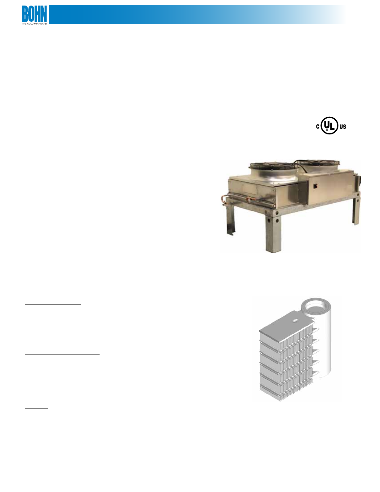
TABLE OF CONTENTS
Features & Benets ........................................................................................................................................................................................... 2-3
Nomenclature .........................................................................................................................................................................................................4
Capacity and Specications ...........................................................................................................................................................................4-6
Condenser Selection ............................................................................................................................................................................................7
Dimensional Diagrams ....................................................................................................................................................................................8-9
Typical Wiring Diagram .....................................................................................................................................................................................10
Overview
Bohn microchannel air-cooled condensers feature
microchannel coil technology. These innovative units
provide signicant refrigerant and energy savings vs.
standard round tube plate n coils.
Key Benefits
Refrigerant Charge Reduction
Microchannel coils oer a very high primary to secondary
surface area ratio. This provides very ecient heat exchange
while maintaining a low internal tube volume. As a result, the
Bohn microchannel condenser reduces condenser refrigerant
charge by over 70% (NRGD02A014 vs. BNED02A015).
Energy Ecient
Bohn microchannel air-cooled condensers feature very
ecient variable speed EC motors. These motors vary speed
based on system requirements to provide optimal energy and
sound performance.
Corrosion Resistance
The mono-metal construction of the microchannel coils
virtually eliminates the risk of galvanic corrosion. A zinc
cladding standard on all coils provides additional corrosion
resistance for harsh environments.
Sound
Microchannel air-cooled condensers feature quiet variable
speed EC fan motors as a standard.
2
© 2011 Heatcraft Refrigeration Products, LLC
Page 3
FEATURES & BENEFITS
Key Benefits Continued
Lighter Weight
Over 30% lighter than comparable round-tube, plate n air-cooled condensers.
Lower Height
Approximately 25% lower cabinet height (with same clearance) than comparable round-tube,
plate n condensers.
Structural Robustness
The coils used in this unit are extremely rigid and resistant to damage.
Warranty
Microchannel air-cooled condensers feature a standard 2 year product warranty, a 2 year
warranty on the microchannel coil and a 3 year warranty on the variable speed EC motors.
Environmentally Friendly
100% recyclable, all -aluminum coil.
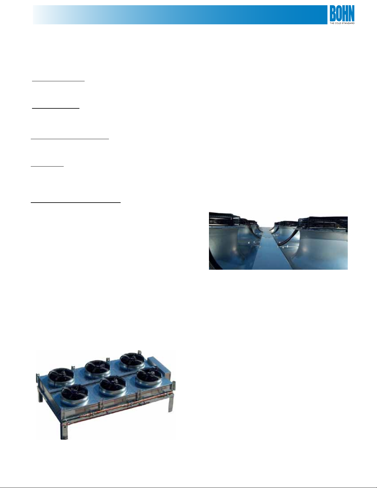
Standard Features
• Microchannel Heat Exchanger
• R-404A, R-407C, R-507, R-407A, R-422D,
and R-410A compatible
• 208-230V/3/60Hz or 460V/3/60Hz
• Factory Installed Manifolding*
• 20” clearance legs
• Copper connection points with schrader access valves
• Factory wired for customer supplied analog signal
• Direct acting, series wired motor control
• Through-the-door non-fused disconnect switch
• End access panels for coil-cleaning
• Internal baes between all fan cells
Optional Features
• 40” Clearance legs
• Individual motor fusing
• Individual motor circuit breakers
• Factory installed analog board:
- CPC
- Danfoss
- Novar
• Motor control & wiring
- Direct acting, parallel wired
- Reverse acting, series wired
- Reverse acting, parallel wired
• Export crating
• Proportional pressure control
* Single circuit standard
3
Page 4
NOMENCLATURE
NR G D 04 A 027
Product Line Motor Identier Width # of Fans Model Identier Standard Capacity
NR = Air Cooled
Condenser w/
Microchannel Coil
Technology
G = 710 mm VSEC D = Dual 02 = 2
04 = 4
06 = 6
08 = 8
A = Current
Revision
(MBH/Degree TD,
R404A)
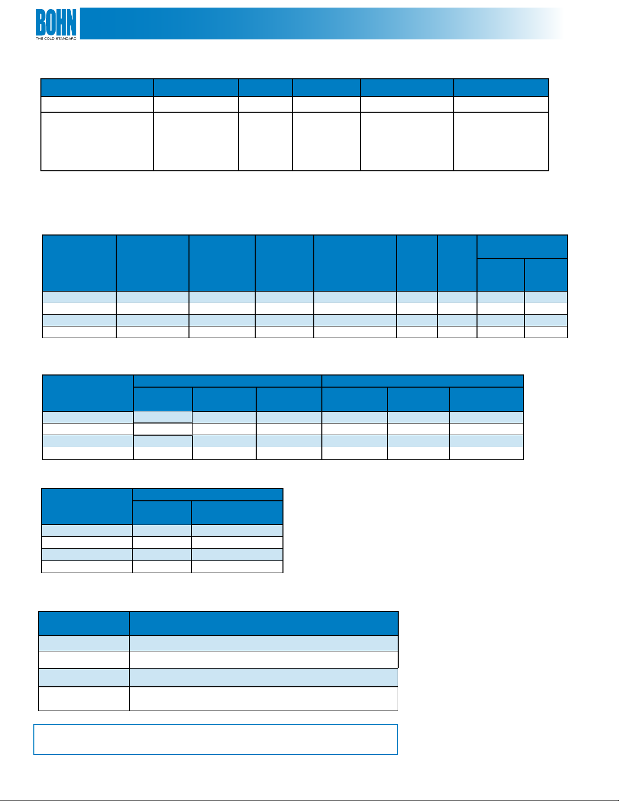
CAPACITY AND SPECIFICATIONS
Condenser Capacities & Specications
R404A
Model Air Mover
NRGD02A014 710 mm VSEC 13.5 13,700 10 470 600 (1) 1-1/8 (1) 7/8
NRGD04A027 710 mm VSEC 27.0 27,400 20 920 1135 (2) 1-1/8 (2) 7/8
NRGD06A041 710 mm VSEC 40.5 41,100 30 1370 1660 (3) 1-1/8 (3) 7/8
NRGD08A054 710 mm VSEC 54.0 54,800 40 1820 2175 (4) 1-1/8 (4) 7/8
* Does not include Manifolding
Capacity
(MBH/1°F
TD)
Full Speed
AirFlow
(ft ³/min)
R404A Flooded
Refrigerant
Charge* (lbs.)
Net
Weight
(lbs.)
Ship
Weight
(lbs.)
Coil Connection
Sizes
Inlet
(in.)
Outlet
(in.)
Condenser Electrical Specications
208-230/3/60 Electrical information 460/3/60 Electrical Information
Model
NRGD02A014
NRGD04A027
NRGD06A041
NRGD08A054
FLA
4.0 15.0 15 2.0 15.0 15
8.0 15.0 15 4.0 15.0 15
12.0 15.0 15 6.0 15.0 15
16.0 20.0 20 8.0 15.0 15
MCA MOPD FLA MCA MOPD
Condenser Manifolding Specications for Single Circuit
Connection Sizes
Model
NRGD02A014 (1) 1-1/8
NRGD04A027 (1) 2-1/8 (1)1-5/8
NRGD06A041 (1) 2-1/8 (1)1-5/8
NRGD08A054 (1) 2-5/8
Note: Contact factory for connection size if not single circuit
Inlet (in.)
Outlet (in.)
(1) 7/8
(1) 2-1/8
Circuiting Options
Model
NRGD02A014
NRGD04A027
Only single circuit available
Single circuit and 50/50 split available
Circuiting
Options Available
NRGD06A041
NRGD08A054
Single circuit, 33/33/33 and 66/33 split available
Single Circuit, 50/50 split and 75/25 split available, also
25/25/25/25 and 50/25/25
Note: These units are optimized for operation at or below 15° T.D.
Operation above 15° T.D. may result in excessive pressure drop.
4
Page 5

CAPACITY AND SPECIFICATIONS
Energy Performance
Condenser Performance Information: Energy Consumption
Unit Energy Consumption (kW)
Typical Operating Range
Model
at 30% Speed
(255 rpm)
NRGD02A014
NRGD04A027
NRGD06A041
NRGD08A054
Power Comparison Chart
0.1 0.3 0.6 1.6
0.2 0.5 1.2 3.2
0.3 0.8 1.8 4.9
0.3 1.0 2.4 6.5
at 50% Speed
(425 rpm)
at 70% Speed
(595 rpm)
at 100% Speed
(850 rpm)
BNHD06A044
BNLD06A042
BNED06A046
NRGD06A041
BNQDO8A041
5
Page 6

CAPACITY AND SPECIFICATIONS
Sound Performance
Condenser Performance Information: Sound Pressure
Sound Pressure (dBA @ 10ft)
Typical Operating Range
at 30% Speed
Model
NRGD02A014 44.3 50.6 57.6 66.5
NRGD04A027
NRGD06A041
NRGD08A054
(255 rpm)
47.3 53.7 60.6 69.5
49.1 55.4 62.4 71.3
50.3 56.7 63.6 72.5
at 50% Speed
(425 rpm)
at 70% Speed
(595 rpm)
at 100% Speed
(850 rpm)
Sound Comparison Chart
Source: http://www.sengpielaudio.com/tableofsoundpressurelevels.htm > Adjusted to 10ft
6
Page 7

CONDENSER SELECTION
Capacity for air-cooled condensers are based on Total Heat of Rejection (THR)
at the condenser. Total heat of rejection is equal to net refrigeration at the
evaporator (compressor capacity) plus the energy input into the refrigerant
by the compressor (heat of compression). The heat of compression will
vary depending on the compressor manufacturer, type of compressor
and the operating conditions of the compressor. Whenever possible, it is
recommended that you obtain the heat of compression value from the
compressor manufacturer.
If this is not available, the THR can be estimated using the following formula:
THR = (Compressor Capacity) * (Heat of Compression Factor, Tables 1 & 2)
Table 1 contains heat of compression factors for suction cooled compressors
and Table 2 contains factors for open drive compressors. For refrigeration
systems beyond the range of Tables 1 and 2, use the following equations to
estimate THR:
Open Compressors:
THR = Compressor Capacity (BTUH) + (2545) * (Break Horsepower, BHP)
Suction Cooled Compressors:
THR = Compressor Capacity (BTUH) + (3413 * KW)
The compressor capacity is aected by its altitude. If the condenser location
is above sea level, an additional correction is required to the THR, as follows:
THR (altitude) = THR * Altitude Correction Factor, Table 3
Selection Example
Compressor capacity: 270,000 BTUH
Evaporator temperature: +25° F
Condensing temperature: 110° F
Ambient temperature 95° F
Refrigerant: R-404A
Compressor type: Semi-hermetic, suction cooled
Condenser type: NRG
Condenser altitude: 1,000 feet
Step 1: Estimate Condenser THR
From Table 1 for suction cooled compressors, at +25° F suction and 115° F
condensing temperature, select a heat of compressor factor of 1.335.
THR = Compressor Capacity * Heat of Compression Factor
= 270,000 * 1.335
= 360,450
Step 2: Correct for Altitude
From Table 3 obtain an altitude correction factor of 1.02 for 1,000 feet.
THR = THR (from step 1) * Altitude Correction Factor (design)
= 360,450 * 1.02
= 367,659
Step 3: Calculate Design Condenser T.D.
Design Condenser T.D. = Condensing Temp — Ambient Temp
= 110°F - 95
= 15° T.D.
Note: These units are optimized for operation at or below 15° T.D.
Operation above 15° T.D. may result in excessive pressure drop.
Step 4: Condenser Selection
Condenser capacitiesare located on page 6. These capacities are given in
MBH/°TD. Convert the THR calculated in step 2 to MBH/°TD by dividing
by 1,000 to get THR in MBH. Then divide the THR by the design TD to get
MBH/°TD.
THR (MBH) = 367,659 / 1,000 = 367.7
THR (MBH/°TD) = 367.7 / 15 = 24.5
Locate the capacity column and read down until you locate a value equal to or
just larger than 24.5. This value is 27.0. Read horizontally to the left to obtain a
condenser model of NRGD04A027
Step 5: Calculate Actual T.D. and Condensing Temperature
The actual condenser T.D. can be calculated by dividing the design THR by
the condenser rating.
Actual T.D. = THR (Design) / (Rating @ 1° T.D.)
= 367.7 / 27.0
= 13.6°F. T.D.
The actual condensing temperature is the actual T.D. plus the ambient
temperature.
Actual Condensing Temperature = (Actual T.D.) + (Ambient)
= 13.6 + 95
= 108.6°F.
Table 1. Heat of Compression Factor for Suction Cooled Compressors.
Suction
Temp. °F
-40° 1.56 1.63 1.72 1.81 1.94
-30° 1.49 1.55 1.62 1.7 1.8
-20° 1.43 1.49 1.55 1.62 1.7
-10° 1.38 1.43 1.49 1.55 1.63
0° 1.34 1.38 1.43 1.49 1.56
5° 1.31 1.36 1.41 1.48 1.55
10° 1.29 1.34 1.39 1.44 1.52
15° 1.26 1.31 1.36 1.41 1.48
20° 1.24 1.28 1.33 1.38 1.44
25° 1.22 1.26 1.31 1.36 1.42
30° 1.2 1.24 1.28 1.33 1.39
40° 1.17 1.2 1.24 1.28 1.33
50° 1.13 1.16 1.2 1.24 1.28
90° 100° 110° 120° 130°
Condensing Temperature °F
Table 2. Heat of Compression Factor for Open Drive Compressors.
Evaporator
Temp. °F
-30° 1.37 1.42 1.47 — — —
-20° 1.33 1.37 1.42 1.47 — —
-10° 1.28 1.32 1.37 1.42 1.47 —
0° 1.24 1.28 1.32 1.37 1.41 1.47
5° 1.23 1.26 1.3 1.35 1.39 1.45
10° 1.21 1.24 1.28 1.32 1.36 1.42
15° 1.19 1.22 1.26 1.3 1.34 1.4
20° 1.17 1.2 1.24 1.28 1.32 1.37
25° 1.16 1.19 1.22 1.26 1.3 1.35
30° 1.14 1.17 1.2 1.24 1.27 1.32
40° 1.12 1.15 1.17 1.2 1.23 1.28
50° 1.09 1.12 1.14 1.17 1.2 1.24
90° 100° 110° 120° 130° 140°
Condensing Temperature °F
Table 3. Altitude Correction Factors.
Altitude Correction Factor
0 1
1,000 1.02
2,000 1.05
3,000 1.07
4,000 1.1
5,000 1.12
6,000 1.15
7,000 1.17
Table 4. Correction Factors.
Correction Factor Capactiy Refrigerant Charge
R-404A
R-22 1.02 1.09
R-410A
R-507 1.00 1.00
50 Hz Power Supply 1.00 --
1.00
1.02
1.00
1.07
7
Page 8

CONDENSER DIMENSIONS
Front View
Note: Drawing shown with standard 20” legs
Side View
2 Fan
4 Fan
6 Fan
8 Fan
* Note:Dimensional drawings include factory manifolding
8
Page 9

CONDENSER DIMENSIONS
Top View
2 Fan
4 Fan
6 Fan
8 Fan
* Note:Dimensional drawings include factory manifolding
9
Page 10
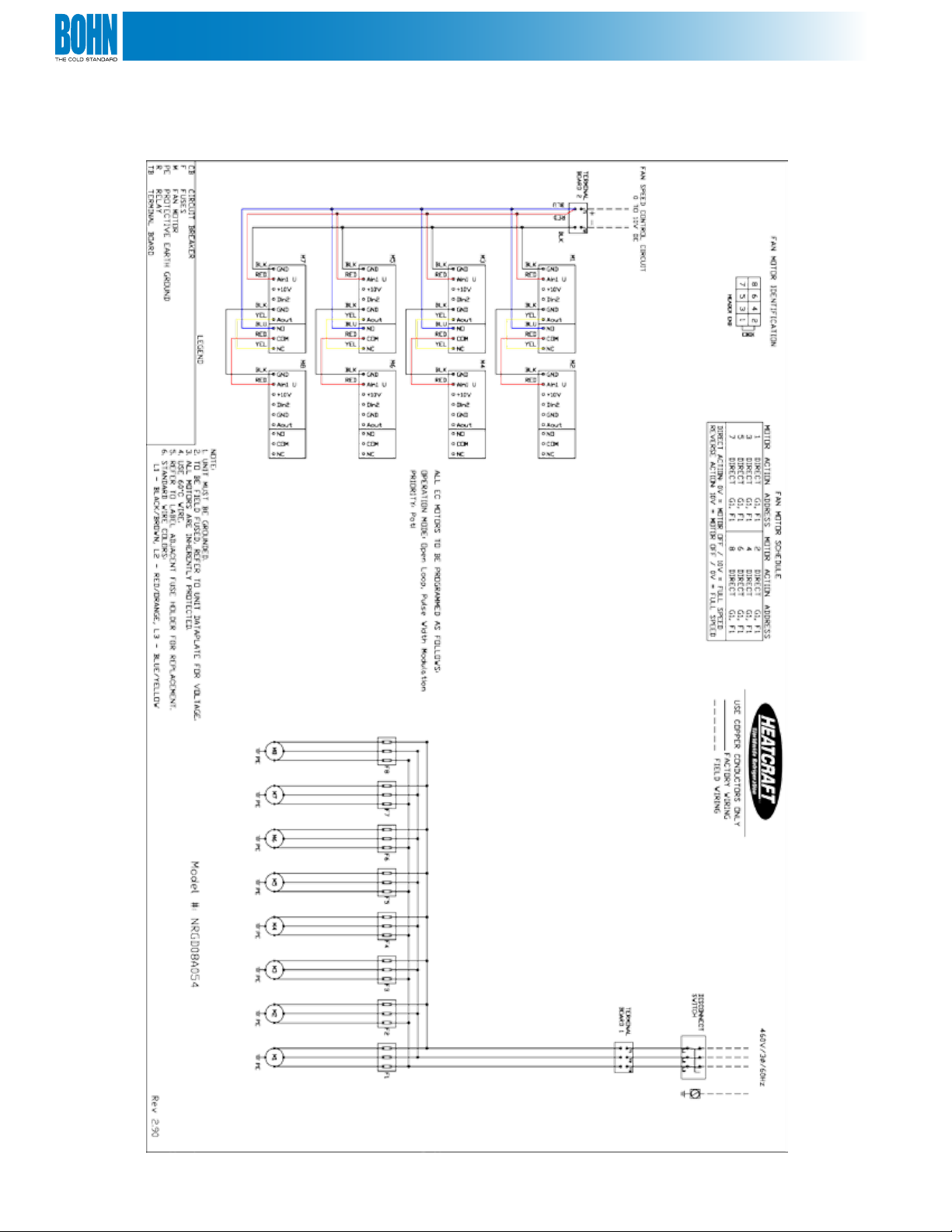
TYPICAL WIRING DIAGRAM
Diagram 1:
10
Page 11

Notes:
11
Page 12

For more information on Bohn refrigeration products, contact
your sales representative or visit us at www.heatcraftrpd.com.
A Brand of Heatcraft Refrigeration Products, LLC
2175 West Park Place Blvd. • Stone Mountain, GA • 30087
800.537.7775
www.heatcraftrpd.com
Since product improvement is a continuing eort, we reserve the right to
make changes in specications without notice.
12
BN-TB-ACCMCX
 Loading...